EP1486678A2 - Compresseur avec deuxième canal de refoulement d' air - Google Patents
Compresseur avec deuxième canal de refoulement d' air Download PDFInfo
- Publication number
- EP1486678A2 EP1486678A2 EP04253327A EP04253327A EP1486678A2 EP 1486678 A2 EP1486678 A2 EP 1486678A2 EP 04253327 A EP04253327 A EP 04253327A EP 04253327 A EP04253327 A EP 04253327A EP 1486678 A2 EP1486678 A2 EP 1486678A2
- Authority
- EP
- European Patent Office
- Prior art keywords
- compressor
- valve
- boost
- housing
- outlet
- Prior art date
- Legal status (The legal status is an assumption and is not a legal conclusion. Google has not performed a legal analysis and makes no representation as to the accuracy of the status listed.)
- Granted
Links
Images


Classifications
-
- F—MECHANICAL ENGINEERING; LIGHTING; HEATING; WEAPONS; BLASTING
- F02—COMBUSTION ENGINES; HOT-GAS OR COMBUSTION-PRODUCT ENGINE PLANTS
- F02B—INTERNAL-COMBUSTION PISTON ENGINES; COMBUSTION ENGINES IN GENERAL
- F02B37/00—Engines characterised by provision of pumps driven at least for part of the time by exhaust
- F02B37/12—Control of the pumps
-
- F—MECHANICAL ENGINEERING; LIGHTING; HEATING; WEAPONS; BLASTING
- F04—POSITIVE - DISPLACEMENT MACHINES FOR LIQUIDS; PUMPS FOR LIQUIDS OR ELASTIC FLUIDS
- F04D—NON-POSITIVE-DISPLACEMENT PUMPS
- F04D27/00—Control, e.g. regulation, of pumps, pumping installations or pumping systems specially adapted for elastic fluids
- F04D27/02—Surge control
- F04D27/0207—Surge control by bleeding, bypassing or recycling fluids
- F04D27/0215—Arrangements therefor, e.g. bleed or by-pass valves
-
- F—MECHANICAL ENGINEERING; LIGHTING; HEATING; WEAPONS; BLASTING
- F01—MACHINES OR ENGINES IN GENERAL; ENGINE PLANTS IN GENERAL; STEAM ENGINES
- F01D—NON-POSITIVE DISPLACEMENT MACHINES OR ENGINES, e.g. STEAM TURBINES
- F01D17/00—Regulating or controlling by varying flow
- F01D17/10—Final actuators
- F01D17/105—Final actuators by passing part of the fluid
-
- F—MECHANICAL ENGINEERING; LIGHTING; HEATING; WEAPONS; BLASTING
- F02—COMBUSTION ENGINES; HOT-GAS OR COMBUSTION-PRODUCT ENGINE PLANTS
- F02B—INTERNAL-COMBUSTION PISTON ENGINES; COMBUSTION ENGINES IN GENERAL
- F02B37/00—Engines characterised by provision of pumps driven at least for part of the time by exhaust
- F02B37/02—Gas passages between engine outlet and pump drive, e.g. reservoirs
- F02B37/025—Multiple scrolls or multiple gas passages guiding the gas to the pump drive
-
- F—MECHANICAL ENGINEERING; LIGHTING; HEATING; WEAPONS; BLASTING
- F02—COMBUSTION ENGINES; HOT-GAS OR COMBUSTION-PRODUCT ENGINE PLANTS
- F02B—INTERNAL-COMBUSTION PISTON ENGINES; COMBUSTION ENGINES IN GENERAL
- F02B37/00—Engines characterised by provision of pumps driven at least for part of the time by exhaust
- F02B37/12—Control of the pumps
- F02B37/18—Control of the pumps by bypassing exhaust from the inlet to the outlet of turbine or to the atmosphere
- F02B37/183—Arrangements of bypass valves or actuators therefor
- F02B37/186—Arrangements of actuators or linkage for bypass valves
-
- F—MECHANICAL ENGINEERING; LIGHTING; HEATING; WEAPONS; BLASTING
- F02—COMBUSTION ENGINES; HOT-GAS OR COMBUSTION-PRODUCT ENGINE PLANTS
- F02B—INTERNAL-COMBUSTION PISTON ENGINES; COMBUSTION ENGINES IN GENERAL
- F02B37/00—Engines characterised by provision of pumps driven at least for part of the time by exhaust
- F02B37/12—Control of the pumps
- F02B37/24—Control of the pumps by using pumps or turbines with adjustable guide vanes
-
- F—MECHANICAL ENGINEERING; LIGHTING; HEATING; WEAPONS; BLASTING
- F02—COMBUSTION ENGINES; HOT-GAS OR COMBUSTION-PRODUCT ENGINE PLANTS
- F02D—CONTROLLING COMBUSTION ENGINES
- F02D23/00—Controlling engines characterised by their being supercharged
-
- F—MECHANICAL ENGINEERING; LIGHTING; HEATING; WEAPONS; BLASTING
- F04—POSITIVE - DISPLACEMENT MACHINES FOR LIQUIDS; PUMPS FOR LIQUIDS OR ELASTIC FLUIDS
- F04D—NON-POSITIVE-DISPLACEMENT PUMPS
- F04D25/00—Pumping installations or systems
- F04D25/02—Units comprising pumps and their driving means
- F04D25/04—Units comprising pumps and their driving means the pump being fluid-driven
-
- F—MECHANICAL ENGINEERING; LIGHTING; HEATING; WEAPONS; BLASTING
- F04—POSITIVE - DISPLACEMENT MACHINES FOR LIQUIDS; PUMPS FOR LIQUIDS OR ELASTIC FLUIDS
- F04D—NON-POSITIVE-DISPLACEMENT PUMPS
- F04D27/00—Control, e.g. regulation, of pumps, pumping installations or pumping systems specially adapted for elastic fluids
- F04D27/02—Surge control
- F04D27/0207—Surge control by bleeding, bypassing or recycling fluids
- F04D27/023—Details or means for fluid extraction
-
- F—MECHANICAL ENGINEERING; LIGHTING; HEATING; WEAPONS; BLASTING
- F04—POSITIVE - DISPLACEMENT MACHINES FOR LIQUIDS; PUMPS FOR LIQUIDS OR ELASTIC FLUIDS
- F04D—NON-POSITIVE-DISPLACEMENT PUMPS
- F04D29/00—Details, component parts, or accessories
- F04D29/40—Casings; Connections of working fluid
- F04D29/42—Casings; Connections of working fluid for radial or helico-centrifugal pumps
- F04D29/4206—Casings; Connections of working fluid for radial or helico-centrifugal pumps especially adapted for elastic fluid pumps
-
- F—MECHANICAL ENGINEERING; LIGHTING; HEATING; WEAPONS; BLASTING
- F04—POSITIVE - DISPLACEMENT MACHINES FOR LIQUIDS; PUMPS FOR LIQUIDS OR ELASTIC FLUIDS
- F04D—NON-POSITIVE-DISPLACEMENT PUMPS
- F04D29/00—Details, component parts, or accessories
- F04D29/70—Suction grids; Strainers; Dust separation; Cleaning
- F04D29/701—Suction grids; Strainers; Dust separation; Cleaning especially adapted for elastic fluid pumps
-
- F—MECHANICAL ENGINEERING; LIGHTING; HEATING; WEAPONS; BLASTING
- F05—INDEXING SCHEMES RELATING TO ENGINES OR PUMPS IN VARIOUS SUBCLASSES OF CLASSES F01-F04
- F05D—INDEXING SCHEME FOR ASPECTS RELATING TO NON-POSITIVE-DISPLACEMENT MACHINES OR ENGINES, GAS-TURBINES OR JET-PROPULSION PLANTS
- F05D2220/00—Application
- F05D2220/40—Application in turbochargers
-
- F—MECHANICAL ENGINEERING; LIGHTING; HEATING; WEAPONS; BLASTING
- F05—INDEXING SCHEMES RELATING TO ENGINES OR PUMPS IN VARIOUS SUBCLASSES OF CLASSES F01-F04
- F05D—INDEXING SCHEME FOR ASPECTS RELATING TO NON-POSITIVE-DISPLACEMENT MACHINES OR ENGINES, GAS-TURBINES OR JET-PROPULSION PLANTS
- F05D2260/00—Function
- F05D2260/60—Fluid transfer
- F05D2260/607—Preventing clogging or obstruction of flow paths by dirt, dust, or foreign particles
-
- Y—GENERAL TAGGING OF NEW TECHNOLOGICAL DEVELOPMENTS; GENERAL TAGGING OF CROSS-SECTIONAL TECHNOLOGIES SPANNING OVER SEVERAL SECTIONS OF THE IPC; TECHNICAL SUBJECTS COVERED BY FORMER USPC CROSS-REFERENCE ART COLLECTIONS [XRACs] AND DIGESTS
- Y02—TECHNOLOGIES OR APPLICATIONS FOR MITIGATION OR ADAPTATION AGAINST CLIMATE CHANGE
- Y02T—CLIMATE CHANGE MITIGATION TECHNOLOGIES RELATED TO TRANSPORTATION
- Y02T10/00—Road transport of goods or passengers
- Y02T10/10—Internal combustion engine [ICE] based vehicles
- Y02T10/12—Improving ICE efficiencies
Definitions
- This invention relates to a compressor with a secondary boost air outlet.
- a compressor may be used to compress gases other than air, and the present. invention is not limited to a compressor which compresses only air.
- air as used throughout this specification should therefore be interpreted as covering any gas.
- the invention relates in particular to a turbocharger incorporating a wastegate and pneumatic wastegate actuator, and more particularly to a command valve arrangement for controlling the operation of the wastegate actuator.
- Turbochargers are well known devices for supplying air to the intake of an internal combustion engine at pressures above atmospheric (boost pressures), and are widely used in automobiles and the like as well as in industrial applications.
- a conventional turbocharger essentially comprises an exhaust gas driven turbine wheel mounted on a rotatable shaft within a turbine housing.
- the turbine housing defines an annular inlet passageway around the turbine wheel and a generally cylindrical axial outlet passageway extending from the turbine wheel.
- Rotation of the turbine wheel rotates a compressor wheel mounted on the other end of the shaft within a compressor housing.
- the rotating compressor wheel compresses inlet air and delivers the compressed air to the intake manifold of the engine, thereby increasing engine power.
- turbochargers with a bypass passageway between the exhaust inlet and the exhaust outlet portions of the turbine housing to enable control of the turbocharger boost pressure and/or shaft speed.
- a wastegate valve is located in the bypass passageway and is controlled to open the passageway when the pressure level of the boost air increases towards a pre-determined level, thus allowing some of the exhaust gas to by-pass the turbine wheel preventing the boost pressure from rising above said level.
- the wastegate valve is generally actuated by a pneumatic actuator operated by boost air pressure delivered by the compressor wheel.
- the conventional pneumatic actuator comprises a spring-loaded diaphragm (or a spring loaded sliding seal) housed within a canister, often referred to as the wastegate actuator can.
- the actuator can is connected by an airline to the compressor outlet and is generally mounted on the compressor housing. Communication with the compressor outlet is via a secondary boost air outlet passage such as a port formed in the compressor housing.
- the diaphragm/sliding seal acts on a connecting rod which extends to the wastegate valve assembly which is mounted in the turbine housing.
- the spring bias is such that under low boost pressure conditions the wastegate valve remains closed.
- the diaphragm is moved against the action of the spring and operates to open the wastegate valve (via the connecting rod) thereby allowing some exhaust gas to bypass the turbine wheel.
- the actuator can is generally connected to the compressor outlet by a flexible hose. In many cases the connection is direct. However, it is also known to provide a bleed valve, also referred to as a command valve, in the airline which responds to appropriate control signals (for instance from the engine management system) to effectively vary the pressure transmitted to the wastegate actuator can by venting to atmosphere. This provides for additional control of the wastegate valve over and above the basic operation dependent upon the pre-determined spring bias. For instance, the command valve may be operated to effectively modify the pressure at which the wastegate valve will begin to open which may be desirable in certain engine operating conditions.
- Wastegate actuator control is not the only situation in which it is necessary to extract boost air from the outlet of a compressor via a secondary boost air outlet passage.
- one conventional method of preventing compressor surge is to install a solenoid valve in an air line ported to the compressor outlet via a secondary boost air outlet passage to controllably vent boost air from the outlet under conditions at which the compressor is likely to surge.
- the vented air may typically be vented to atmosphere via a silencer or returned to the compressor inlet for re-circulation through the compressor.
- valve is used to control the boost air flow through the secondary boost air outlet passage
- some valves are constructed largely from plastic and therefore must be mounted away from the turbocharger at a cool part of the engine.
- remote mounting of the valve (whatever its function) requires extra air lines and associated fittings.
- a solution to this problem is provided by Japanese patent application S62-35565 (laid-open patent application S 63-205419 filed in February 1987). This discloses mounting a solenoid valve directly to the compressor housing in order to avoid extra air line connections between the valve and the compressor.
- the compressor housing is provided with an integral valve mount located on an outside surface of the housing and including a first air port in communication with the compressor outlet volute and a second air port in communication with the compressor air intake.
- the mount has means for attaching the solenoid valve and forming a leak-tight seal between the valve and the first and second air ports provided in the valve mount.
- the solenoid valve is provided for surge prevention and thus operates to selectively control flow of boost air from the compressor outlet to the compressor inlet (via the first and second air ports respectively) to avoid surge.
- Exactly the same valve mounting arrangement has been used for mounting a wastegate actuator command valve, see for instance US 6,205,784.
- a problem with the known arrangements for extracting air from a compressor outlet via a secondary boost air outlet passage is that any oil, dirt etc present in the air is fed to the downstream component (such as a valve or wastegate actuator) which over time can compromise the operation of the component.
- the downstream component such as a valve or wastegate actuator
- valve ports can become at least partially clogged by the build-up of oil and particulate material present in the boost air.
- CCV closed crank case ventilation system
- Closed cranked case ventilation is becoming increasingly prevalent in order to meet modem stringent exhaust emission regulations.
- a compressor for compressing a gas comprising a compressor wheel rotatably mounted within a compressor housing, the compressor housing having a gas inlet and having a gas outlet volute disposed around the compressor wheel, and defined by an inner surface or surfaces of the housing, for supplying gas at boost pressures, a secondary boost gas outlet passage provided in communication with the outlet volute, wherein the secondary boost gas outlet passage is defined at least in part by a projection which extends into the volute so that the upstream end of the passage opens at a location spaced from the volute surface.
- the amount of oil/dirt etc passing into the passage can be reduced or eliminated entirely. This is because the oil/dirt etc is centrifuged to the volute surface by the gas flow swirling through the volute and the air flow away from the surface is clean.
- a wastegated turbocharger comprising:
- a wastegated turbocharger comprising:
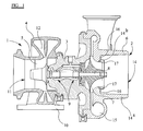
- FIG. 1 illustrates the basic components of a conventional centripetal type turbocharger.
- the turbocharger comprises a turbine 1 joined to a compressor 2 via a central bearing housing 3.
- the turbine 1 comprises a turbine housing 4 which houses a turbine wheel 5.
- the compressor 2 comprises a compressor housing 6 which houses a compressor wheel 7.
- the turbine wheel 5 and compressor wheel 7 are mounted on opposite ends of a common shaft 8 which is supported on bearing assemblies 9 within the bearing housing 3.
- the turbine housing 4 is provided with an exhaust gas inlet 10 and an exhaust gas outlet 11.
- the inlet 10 directs incoming exhaust gas to an annular inlet chamber 12 which forms a volute surrounding the turbine wheel 5.
- the exhaust gas flows through the turbine 1 and into the outlet 11 via a circular outlet opening 13 which is co-axial with the turbine wheel 5.
- the compressor comprises an inlet 14 and an outlet volute 15 co-axial with the compressor wheel 7. As the compressor wheel rotates, air intake is drawn in through the inlet 14, compressed and delivered to the engine via outlet volute 15.
- the illustrated compressor 2 has a map width enhanced (MWE) inlet structure comprising two co-axial tubular inlet sections 14a and 14b.
- the inner inlet section 14b is shorter than the outer inlet section 14a and has an inner surface which is an extension of a surface of the inner wall of the compressor housing which faces the compressor wheel 7.
- the outer inlet portion 14a is located radially outside the inner inlet portion 14b to define an annular inlet passage 16 therebetween.
- Apertures 17 are formed through the housing at the downstream end of the outer inlet portion 14a and open into the inner surface of the compressor housing adjacent the compressor wheel 7.
- intake air is drawn into the compressor housing through the inner inlet portion 14b and also through the annular passage 16 and apertures 17.
- the pressure drop across the apertures 17 falls and eventually reverses, at which time the airflow direction in the annular passage 16 also reverses such that some of the air entering the housing through the inner inlet portion 14b is recirculated. This stabilises the compressor performance in a well known way.
- FIG 2 this illustrates components of a conventional wastegate valve and wastegate actuator assembly which is not visible from figure 1.
- the turbine housing 4 is provided with a bypass passageway (not shown) which communicates between the exhaust inlet 10 and the exhaust outlet bypassing the turbine wheel.
- the bypass passageway communicates with the exhaust inlet 10 via a circular opening (not shown) which is opened and closed by a wastegate valve assembly 18 provided for controlling the flow therethrough.
- the part of the turbine housing 4 defining the inlet 10 is shown partially cut-away to reveal details of the wastegate valve assembly 18.
- the wastegate valve assembly 18 is controlled by a pneumatic wastegate actuator 19 which is linked to the valve assembly 18 via a connecting rod 20.
- the actuator can 19 receives compressed air from the outlet of the compressor 2 via an airhose (not shown) communicating with a secondary boost av outlet passage (not shown) provided through the compressing housing with the outlet volute fitted to nipple 21 and communicating with a port (not shown) provided in the compressor housing.
- the compressor can 19 is conventionally mounted to the outside of the compressor housing by an appropriate bracket (not shown). Details of the wastegate valve assembly 18, the actuator can 19, and the mounting arrangements for securing the actuator can 19 to the compressor are not important to an understanding of the present invention (and may be entirely conventional) and thus will not be described further.
- FIG 3 is a perspective external illustration of a wastegated turbocharger fitted with a wastegate command valve 22 and incorporating the present invention. Common reference numerals are used to identify components shown in figures 1 and 2.
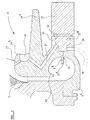
- FIG 4 this is an enlarged cross-section of part of the compressor housing of figure 3.
- the compressor housing in this case the compressor cover 6a, is formed with a valve mounting boss 23 which defines an internal opening 24 for receiving one end 22a of the command valve 22 (as illustrated the valve end 22a is screwed into the boss 23 but other fixing arrangements may be provided to suit the form of valve 22).
- the compressor cover 6a is provided with three internal bores 25, 26 & 27 which communicate with the boss opening 24 and with respective ports of the command valve 22.
- the first bore 25 is the secondary boost air outlet passage which communicates with the compressor outlet volute 15 to deliver boost air to the valve 22.
- the second bore 26 is a boost air supply passage and opens to the outer surface of the compressor cover 6a and is provided to supply boost air from the valve 22 to the wastegate actuator via an appropriate hose connection shown by chain dot lines 28.
- the third bore 27 is a boost air vent passage and communicates with the compressor inlet in the region of the annular inlet passage 16.
- the secondary boost air outlet passage 25 projects into the outlet volute 15 so that the opening 25a at the upstream end of the passage 25 is spaced from the surface 15a of the volute 15.
- This seemingly simple expedient significantly reduces, and even entirely eliminates, the passage of oil/dirt etc through the secondary boost passage 25. This is because any oil/dirt particles etc are centrifuged onto the volute wall 15a by the gas flow which swirls through the outlet volute 15. Accordingly, air flowing through the volute away from the volute surface 15a is cleaner than the air flow close to the volute surface 15a.
- Each of the bores 26 and 27 may be formed by drilling through the compressor cover 6a and boss 24.
- the boost air vent bore 27 is formed from two angled portions which may be drilled separately from within the compressor inlet and boss opening 24 respectively. It will, however, be appreciated that in other compressor housing designs it may be possible to provide a straight boost air vent bore between the command valve and the compressor inlet. Similarly, it will be understood that the bores 26 and 27 could be cast rather than drilled.
- the command valve 22 is a conventional three port proportional solenoid valve which is operable to selectively connect the boost air inlet bore 25 with either the boost air outlet bore 26 or boost air vent bore 27 in response to an appropriate control signal (received from the engine management system or other appropriate sensor/control arrangement).
- the valve 22 may thus be operated in essentially the same manner as a conventional wastegate actuator command valve to control the boost air supply to the wastegate actuator in accordance with normal operating parameters. Since the valve itself may be entirely conventional, no details of any particular valve will be described, but it should be borne in mind that the valve must be capable of withstanding the relatively high temperature generated at the compressor and an appropriate valve should be selected accordingly.
- the projection into the volute 15 may be formed as an integral casting formation 6b with the compressor housing 6a.
- the bore 25 could either be cast or drilled post-casting.
- casting such a projection complicates the casting process and thus may add to manufacturing expense.
- Figure 5 One alternative is illustrated in Figure 5.
- the structure illustrated in Figure 5 is the same as that illustrated in Figure 3 except that the secondary boost air outlet passage is defined by a member 29 which is fitted into the boss opening 24 and extends through an aperture 30 which may simply be drilled into the housing 6a through the bottom of the opening 24.
- Figure 5 is only a schematic drawing, and it will be appreciated that additional features, such as annular seals etc, may be provided to prevent gas leaking between the aperture 30 and member 29.
- valve 22 is modified by provision of an elongate nose or stem 31 (which is directly equivalent to the projecting portion 6b of Figure 5) which extends through an aperture 30 when the valve is installed in the valve mounting boss 23 (vent port 27 is not visible in Figures 6 and 7). Also shown in Figures 6 and 7 are O-ring seals 23a provided to provide an air-tight seal between the valve 22 and mounting boss 23.
- inventions of Figures 6 and 7 differ from one another in that in the embodiment of Figure 7 the aperture 30 is sized to receive.only the nose portion 31 of the valve whereas with the embodiment of Figure 7 the aperture 30 is enlarged to receive a relatively large diameter end portion of the valve 22.
- the latter arrangement avoids the need for a separate drilling to form the aperture 30 which instead is formed by a drilling which defines a part of the boss opening 24.
- valve mounting boss dependent upon the design of the command valve intended to be used and to the size and positioning of the boost air inlet, outlet and. vent bores, as well as the precise location at which these bores open to the compressor inlet, outlet and outer surface of the compressor housing.
- wastegate actuator or wastegate valve assembly can be applied wherever a command valve is desirable to control operation of a pneumatic wastegate actuator.
- command valve itself can be controlled in accordance with any conventional methods and engine performance parameters to provide the same control as a conventional wastegate actuator command valve.
- Valves intended for other purposes may be installed and that the invention is not limited for use in application with wastegate actuator command valves.
- a valve operated to prevent compressor surge may be installed as suggested by the Japanese patent application mentioned in the introduction to this specification.
- Figure 8 schematically illustrates an adapter member 32 installed in an aperture 34 provided through a compressor housing 6.
- One end of the adapter 32 defines a secondary boost air outlet passage 33 which projects into the compressor volute 15, and the other end of the adapter 32 provides a fitting 34 for attachment of an air hose (not shown) for feeding the boost air to a remotely located valve.
- the adapter 32 is preferably screwed into the aperture 34, and in order to provide sufficiently long screw thread the compressor housing 6 is preferably formed with a boss 35 through which the aperture 34 is drilled.
- the air need not necessarily be supplied to.. a downstream valve but could, for instance, be supplied directly to a wastegate actuator or other component.
Landscapes
- Engineering & Computer Science (AREA)
- Mechanical Engineering (AREA)
- General Engineering & Computer Science (AREA)
- Chemical & Material Sciences (AREA)
- Combustion & Propulsion (AREA)
- Life Sciences & Earth Sciences (AREA)
- Sustainable Development (AREA)
- Supercharger (AREA)
- Structures Of Non-Positive Displacement Pumps (AREA)
Applications Claiming Priority (2)
| Application Number | Priority Date | Filing Date | Title |
|---|---|---|---|
| GBGB0313399.8A GB0313399D0 (en) | 2003-06-11 | 2003-06-11 | Compressor with secondary boost air outlet passage |
| GB0313399 | 2003-06-11 |
Publications (3)
| Publication Number | Publication Date |
|---|---|
| EP1486678A2 true EP1486678A2 (fr) | 2004-12-15 |
| EP1486678A3 EP1486678A3 (fr) | 2008-02-13 |
| EP1486678B1 EP1486678B1 (fr) | 2011-10-05 |
Family
ID=27589818
Family Applications (1)
| Application Number | Title | Priority Date | Filing Date |
|---|---|---|---|
| EP04253327A Expired - Lifetime EP1486678B1 (fr) | 2003-06-11 | 2004-06-04 | Compresseur avec deuxième canal de refoulement d' air |
Country Status (6)
| Country | Link |
|---|---|
| US (1) | US7210295B2 (fr) |
| EP (1) | EP1486678B1 (fr) |
| JP (1) | JP4471741B2 (fr) |
| KR (1) | KR20040106243A (fr) |
| CN (1) | CN100564841C (fr) |
| GB (1) | GB0313399D0 (fr) |
Cited By (7)
| Publication number | Priority date | Publication date | Assignee | Title |
|---|---|---|---|---|
| WO2008071252A1 (fr) * | 2006-12-11 | 2008-06-19 | Borgwarner Inc. | Turbocompresseur |
| WO2008125381A1 (fr) * | 2007-04-16 | 2008-10-23 | Continental Automotive Gmbh | Carter de compresseur et turbocompresseur |
| FR2923541A1 (fr) * | 2007-11-13 | 2009-05-15 | Snecma Sa | Vanne de decharge dans une turbomachine |
| DE102011007720A1 (de) | 2011-04-20 | 2012-10-25 | Schaeffler Technologies AG & Co. KG | Turbolader mit Bowdenzug gesteuertem Wastegate |
| US9103271B2 (en) | 2013-04-04 | 2015-08-11 | Ford Global Technologies, Llc | Exhaust leakage management |
| FR3027973A1 (fr) * | 2014-10-29 | 2016-05-06 | Snecma | Carter de turbomachine, comprenant un dispositif de guidage de l'air en rotation dans le carter |
| EP2864597A4 (fr) * | 2012-06-20 | 2016-06-15 | United Technologies Corp | Orifices de purge inter-compresseurs aérodynamiques usinés |
Families Citing this family (17)
| Publication number | Priority date | Publication date | Assignee | Title |
|---|---|---|---|---|
| WO2009111223A2 (fr) * | 2008-02-29 | 2009-09-11 | Borgwarner Inc. | Système de turbochargement à multi-étages à dérivation thermique |
| JP2010025104A (ja) * | 2008-07-16 | 2010-02-04 | Borgwarner Inc | 後処理装置の受動的暖機制御用熱操作バイパス弁 |
| US8166756B2 (en) * | 2009-04-17 | 2012-05-01 | China Engine Corporation | Turbine intake pressure release structure |
| US8117841B2 (en) * | 2009-07-17 | 2012-02-21 | Eckart Industrial Corporation | Self regulating waste gate |
| JP5272942B2 (ja) * | 2009-07-21 | 2013-08-28 | 株式会社Ihi | ターボ圧縮機及び冷凍機 |
| US8814499B2 (en) * | 2010-04-19 | 2014-08-26 | Korea Fluid Machinery Co., Ltd. | Centrifugal compressor |
| KR101858169B1 (ko) * | 2010-10-28 | 2018-06-28 | 보르그워너 인코퍼레이티드 | 배기가스 터보차저 |
| US9011086B2 (en) * | 2011-12-07 | 2015-04-21 | Honeywell International Inc. | Treated valve seat |
| US9163523B2 (en) | 2012-06-25 | 2015-10-20 | Cummins Inc. | Turbocharger with flexible installation |
| JP6040727B2 (ja) * | 2012-11-21 | 2016-12-07 | 株式会社Ihi | 過給機 |
| GB201312505D0 (en) * | 2013-07-12 | 2013-08-28 | Cummins Ltd | Turbine |
| CN104235030A (zh) * | 2014-09-12 | 2014-12-24 | 诸文伟 | 一种天然气输送离心压缩机 |
| CN105065330A (zh) * | 2015-08-06 | 2015-11-18 | 中国北方发动机研究所(天津) | 一种共享扩压器下双进气涡轮增压器压气机结构 |
| US10934943B2 (en) | 2017-04-27 | 2021-03-02 | General Electric Company | Compressor apparatus with bleed slot and supplemental flange |
| KR102463503B1 (ko) * | 2018-07-11 | 2022-11-03 | 현대자동차주식회사 | 터보차저 엔진의 부스트압 제어 시스템 |
| CN112983846A (zh) * | 2019-12-02 | 2021-06-18 | 开利公司 | 离心压缩机和运行离心压缩机的方法 |
| EP4053386A1 (fr) * | 2021-03-04 | 2022-09-07 | Volvo Car Corporation | Compresseur monté sur vilebrequin |
Citations (1)
| Publication number | Priority date | Publication date | Assignee | Title |
|---|---|---|---|---|
| US6205784B1 (en) | 1999-07-27 | 2001-03-27 | Alliedsignal Inc. | Integrally mounted pneumatic solenoid valve for wastegate control |
Family Cites Families (14)
| Publication number | Priority date | Publication date | Assignee | Title |
|---|---|---|---|---|
| FR849528A (fr) * | 1939-01-23 | 1939-11-25 | Perfectionnements apportés aux pompes et compresseurs, principalement centrifuges, notamment à ceux utilisés pour injecter des combustibles | |
| FR1413114A (fr) * | 1964-06-13 | 1965-10-08 | Dispositif permettant d'augmenter la pression d'air d'un ventilateur centrifuge sur une partie de la volute | |
| US3740163A (en) * | 1971-02-25 | 1973-06-19 | Garrett Corp | Fluid bearing inertial filter |
| US4171936A (en) | 1978-03-13 | 1979-10-23 | General Motors Corporation | Engine turbocharger with integral wastegate |
| JPS5856337Y2 (ja) | 1978-11-22 | 1983-12-26 | 株式会社小松製作所 | タ−ボチヤ−ジヤ |
| JPS595772B2 (ja) | 1979-01-10 | 1984-02-07 | 株式会社日立製作所 | 排気バイパス式タ−ボチヤ−ジヤ |
| US4655043A (en) | 1983-05-26 | 1987-04-07 | The Garrett Corporation | Turbocharger |
| US4629394A (en) * | 1983-07-25 | 1986-12-16 | Chandler Evans Inc | Centrifugal pump having low flow diffuser |
| JPS63205419A (ja) | 1987-02-20 | 1988-08-24 | Hitachi Ltd | 排気タ−ビン過給機 |
| US5113670A (en) * | 1990-08-03 | 1992-05-19 | United Technologies Corporation | Bearing cooling arrangement for air cycle machine |
| US6155048A (en) | 1997-09-29 | 2000-12-05 | Gits Manufacturing Company | Actuator for a turbocharger |
| GB9816277D0 (en) * | 1998-07-27 | 1998-09-23 | Holset Engineering Co | Turbocharger with wastegate actuator |
| US6729134B2 (en) * | 2001-01-16 | 2004-05-04 | Honeywell International Inc. | Variable geometry turbocharger having internal bypass exhaust gas flow |
| DE10133669A1 (de) * | 2001-07-11 | 2003-01-30 | Daimler Chrysler Ag | Abgasturbolader in einer Brennkraftmaschine |
-
2003
- 2003-06-11 GB GBGB0313399.8A patent/GB0313399D0/en not_active Ceased
-
2004
- 2004-06-03 US US10/860,619 patent/US7210295B2/en not_active Expired - Lifetime
- 2004-06-04 EP EP04253327A patent/EP1486678B1/fr not_active Expired - Lifetime
- 2004-06-10 KR KR1020040042749A patent/KR20040106243A/ko not_active Application Discontinuation
- 2004-06-11 JP JP2004174096A patent/JP4471741B2/ja not_active Expired - Fee Related
- 2004-06-11 CN CNB2004100714614A patent/CN100564841C/zh active Active
Patent Citations (1)
| Publication number | Priority date | Publication date | Assignee | Title |
|---|---|---|---|---|
| US6205784B1 (en) | 1999-07-27 | 2001-03-27 | Alliedsignal Inc. | Integrally mounted pneumatic solenoid valve for wastegate control |
Cited By (10)
| Publication number | Priority date | Publication date | Assignee | Title |
|---|---|---|---|---|
| WO2008071252A1 (fr) * | 2006-12-11 | 2008-06-19 | Borgwarner Inc. | Turbocompresseur |
| WO2008125381A1 (fr) * | 2007-04-16 | 2008-10-23 | Continental Automotive Gmbh | Carter de compresseur et turbocompresseur |
| FR2923541A1 (fr) * | 2007-11-13 | 2009-05-15 | Snecma Sa | Vanne de decharge dans une turbomachine |
| EP2060746A1 (fr) | 2007-11-13 | 2009-05-20 | Snecma | Vanne de décharge dans une turbomachine |
| US8152137B2 (en) | 2007-11-13 | 2012-04-10 | Snecma | Relief valve in a turbomachine |
| DE102011007720A1 (de) | 2011-04-20 | 2012-10-25 | Schaeffler Technologies AG & Co. KG | Turbolader mit Bowdenzug gesteuertem Wastegate |
| EP2864597A4 (fr) * | 2012-06-20 | 2016-06-15 | United Technologies Corp | Orifices de purge inter-compresseurs aérodynamiques usinés |
| US9638201B2 (en) | 2012-06-20 | 2017-05-02 | United Technologies Corporation | Machined aerodynamic intercompressor bleed ports |
| US9103271B2 (en) | 2013-04-04 | 2015-08-11 | Ford Global Technologies, Llc | Exhaust leakage management |
| FR3027973A1 (fr) * | 2014-10-29 | 2016-05-06 | Snecma | Carter de turbomachine, comprenant un dispositif de guidage de l'air en rotation dans le carter |
Also Published As
| Publication number | Publication date |
|---|---|
| GB0313399D0 (en) | 2003-07-16 |
| US7210295B2 (en) | 2007-05-01 |
| JP4471741B2 (ja) | 2010-06-02 |
| KR20040106243A (ko) | 2004-12-17 |
| EP1486678A3 (fr) | 2008-02-13 |
| CN100564841C (zh) | 2009-12-02 |
| EP1486678B1 (fr) | 2011-10-05 |
| CN1573058A (zh) | 2005-02-02 |
| JP2005003002A (ja) | 2005-01-06 |
| US20040255581A1 (en) | 2004-12-23 |
Similar Documents
| Publication | Publication Date | Title |
|---|---|---|
| US7210295B2 (en) | Compressor with secondary boost air outlet passage | |
| US9506383B2 (en) | Blow-by gas refluxing device | |
| US5857337A (en) | Turbocharger | |
| US6474318B1 (en) | Air induction system having inlet valve | |
| US7578129B2 (en) | Multiple-turbocharger system, and exhaust gas flow control valve therefor | |
| US6205784B1 (en) | Integrally mounted pneumatic solenoid valve for wastegate control | |
| WO2004094822A3 (fr) | Compresseur d'air a mecanisme de regulation d'entree d'air et mecanisme de regulation d'entree automatique | |
| US5159815A (en) | Turbocharged internal combustion engine | |
| US20030029168A1 (en) | Method and apparatus to control a turbocharger wastegate using exhaust pressure | |
| US5199260A (en) | Wastegate actuator control valve for a turbocharger | |
| KR101189228B1 (ko) | Cng엔진의 공기량 제어장치 | |
| CN109964038A (zh) | 用于商用车的螺杆式压缩机系统 | |
| AU2018253619B2 (en) | Boost Device Diverter Valve System | |
| CN109964037A (zh) | 用于商用车的螺杆式压缩机系统 | |
| KR100531603B1 (ko) | 터빈 배기가스 재순환 제어밸브 및 배기가스바이패스밸브와 일체로 된 터보차저 | |
| CA2762327A1 (fr) | Boitier d'un dispositif d'alimentation en gaz frais pour une machine a combustion interne, ainsi que dispositif d'alimentation en gaz frais | |
| CA2229352C (fr) | Vanne de purge de compresseur | |
| JP2003278553A (ja) | 可変容量ターボチャージャ |
Legal Events
| Date | Code | Title | Description |
|---|---|---|---|
| PUAI | Public reference made under article 153(3) epc to a published international application that has entered the european phase |
Free format text: ORIGINAL CODE: 0009012 |
|
| AK | Designated contracting states |
Kind code of ref document: A2 Designated state(s): AT BE BG CH CY CZ DE DK EE ES FI FR GB GR HU IE IT LI LU MC NL PL PT RO SE SI SK TR |
|
| AX | Request for extension of the european patent |
Extension state: AL HR LT LV MK |
|
| PUAL | Search report despatched |
Free format text: ORIGINAL CODE: 0009013 |
|
| AK | Designated contracting states |
Kind code of ref document: A3 Designated state(s): AT BE BG CH CY CZ DE DK EE ES FI FR GB GR HU IE IT LI LU MC NL PL PT RO SE SI SK TR |
|
| AX | Request for extension of the european patent |
Extension state: AL HR LT LV MK |
|
| RIC1 | Information provided on ipc code assigned before grant |
Ipc: F02C 6/12 20060101ALI20080109BHEP Ipc: F02B 37/18 20060101ALI20080109BHEP Ipc: F01D 17/10 20060101ALI20080109BHEP Ipc: F04D 27/02 20060101ALI20080109BHEP Ipc: F04D 29/42 20060101ALI20080109BHEP Ipc: F04D 25/04 20060101AFI20040920BHEP |
|
| 17P | Request for examination filed |
Effective date: 20080319 |
|
| 17Q | First examination report despatched |
Effective date: 20080707 |
|
| AKX | Designation fees paid |
Designated state(s): DE FR GB |
|
| GRAP | Despatch of communication of intention to grant a patent |
Free format text: ORIGINAL CODE: EPIDOSNIGR1 |
|
| GRAS | Grant fee paid |
Free format text: ORIGINAL CODE: EPIDOSNIGR3 |
|
| GRAA | (expected) grant |
Free format text: ORIGINAL CODE: 0009210 |
|
| AK | Designated contracting states |
Kind code of ref document: B1 Designated state(s): DE FR GB |
|
| REG | Reference to a national code |
Ref country code: GB Ref legal event code: FG4D |
|
| REG | Reference to a national code |
Ref country code: DE Ref legal event code: R096 Ref document number: 602004034644 Country of ref document: DE Effective date: 20111215 |
|
| PLBE | No opposition filed within time limit |
Free format text: ORIGINAL CODE: 0009261 |
|
| STAA | Information on the status of an ep patent application or granted ep patent |
Free format text: STATUS: NO OPPOSITION FILED WITHIN TIME LIMIT |
|
| 26N | No opposition filed |
Effective date: 20120706 |
|
| REG | Reference to a national code |
Ref country code: DE Ref legal event code: R097 Ref document number: 602004034644 Country of ref document: DE Effective date: 20120706 |
|
| REG | Reference to a national code |
Ref country code: FR Ref legal event code: PLFP Year of fee payment: 13 |
|
| REG | Reference to a national code |
Ref country code: FR Ref legal event code: PLFP Year of fee payment: 14 |
|
| REG | Reference to a national code |
Ref country code: FR Ref legal event code: PLFP Year of fee payment: 15 |
|
| PGFP | Annual fee paid to national office [announced via postgrant information from national office to epo] |
Ref country code: FR Payment date: 20190625 Year of fee payment: 16 |
|
| PGFP | Annual fee paid to national office [announced via postgrant information from national office to epo] |
Ref country code: DE Payment date: 20190627 Year of fee payment: 16 |
|
| REG | Reference to a national code |
Ref country code: DE Ref legal event code: R119 Ref document number: 602004034644 Country of ref document: DE |
|
| PG25 | Lapsed in a contracting state [announced via postgrant information from national office to epo] |
Ref country code: FR Free format text: LAPSE BECAUSE OF NON-PAYMENT OF DUE FEES Effective date: 20200630 |
|
| PG25 | Lapsed in a contracting state [announced via postgrant information from national office to epo] |
Ref country code: DE Free format text: LAPSE BECAUSE OF NON-PAYMENT OF DUE FEES Effective date: 20210101 |
|
| P01 | Opt-out of the competence of the unified patent court (upc) registered |
Effective date: 20230510 |
|
| PGFP | Annual fee paid to national office [announced via postgrant information from national office to epo] |
Ref country code: GB Payment date: 20230627 Year of fee payment: 20 |