EP1486677B1 - Rotary compressor - Google Patents
Rotary compressor Download PDFInfo
- Publication number
- EP1486677B1 EP1486677B1 EP03707027A EP03707027A EP1486677B1 EP 1486677 B1 EP1486677 B1 EP 1486677B1 EP 03707027 A EP03707027 A EP 03707027A EP 03707027 A EP03707027 A EP 03707027A EP 1486677 B1 EP1486677 B1 EP 1486677B1
- Authority
- EP
- European Patent Office
- Prior art keywords
- swing piston
- swing
- peripheral surface
- piston
- blade
- Prior art date
- Legal status (The legal status is an assumption and is not a legal conclusion. Google has not performed a legal analysis and makes no representation as to the accuracy of the status listed.)
- Expired - Lifetime
Links
Images


Classifications
-
- F—MECHANICAL ENGINEERING; LIGHTING; HEATING; WEAPONS; BLASTING
- F04—POSITIVE - DISPLACEMENT MACHINES FOR LIQUIDS; PUMPS FOR LIQUIDS OR ELASTIC FLUIDS
- F04C—ROTARY-PISTON, OR OSCILLATING-PISTON, POSITIVE-DISPLACEMENT MACHINES FOR LIQUIDS; ROTARY-PISTON, OR OSCILLATING-PISTON, POSITIVE-DISPLACEMENT PUMPS
- F04C18/00—Rotary-piston pumps specially adapted for elastic fluids
- F04C18/30—Rotary-piston pumps specially adapted for elastic fluids having the characteristics covered by two or more of groups F04C18/02, F04C18/08, F04C18/22, F04C18/24, F04C18/48, or having the characteristics covered by one of these groups together with some other type of movement between co-operating members
- F04C18/34—Rotary-piston pumps specially adapted for elastic fluids having the characteristics covered by two or more of groups F04C18/02, F04C18/08, F04C18/22, F04C18/24, F04C18/48, or having the characteristics covered by one of these groups together with some other type of movement between co-operating members having the movement defined in group F04C18/08 or F04C18/22 and relative reciprocation between the co-operating members
- F04C18/356—Rotary-piston pumps specially adapted for elastic fluids having the characteristics covered by two or more of groups F04C18/02, F04C18/08, F04C18/22, F04C18/24, F04C18/48, or having the characteristics covered by one of these groups together with some other type of movement between co-operating members having the movement defined in group F04C18/08 or F04C18/22 and relative reciprocation between the co-operating members with vanes reciprocating with respect to the outer member
-
- F—MECHANICAL ENGINEERING; LIGHTING; HEATING; WEAPONS; BLASTING
- F04—POSITIVE - DISPLACEMENT MACHINES FOR LIQUIDS; PUMPS FOR LIQUIDS OR ELASTIC FLUIDS
- F04C—ROTARY-PISTON, OR OSCILLATING-PISTON, POSITIVE-DISPLACEMENT MACHINES FOR LIQUIDS; ROTARY-PISTON, OR OSCILLATING-PISTON, POSITIVE-DISPLACEMENT PUMPS
- F04C18/00—Rotary-piston pumps specially adapted for elastic fluids
- F04C18/30—Rotary-piston pumps specially adapted for elastic fluids having the characteristics covered by two or more of groups F04C18/02, F04C18/08, F04C18/22, F04C18/24, F04C18/48, or having the characteristics covered by one of these groups together with some other type of movement between co-operating members
- F04C18/32—Rotary-piston pumps specially adapted for elastic fluids having the characteristics covered by two or more of groups F04C18/02, F04C18/08, F04C18/22, F04C18/24, F04C18/48, or having the characteristics covered by one of these groups together with some other type of movement between co-operating members having both the movement defined in group F04C18/02 and relative reciprocation between the co-operating members
- F04C18/322—Rotary-piston pumps specially adapted for elastic fluids having the characteristics covered by two or more of groups F04C18/02, F04C18/08, F04C18/22, F04C18/24, F04C18/48, or having the characteristics covered by one of these groups together with some other type of movement between co-operating members having both the movement defined in group F04C18/02 and relative reciprocation between the co-operating members with vanes hinged to the outer member and reciprocating with respect to the outer member
-
- F—MECHANICAL ENGINEERING; LIGHTING; HEATING; WEAPONS; BLASTING
- F01—MACHINES OR ENGINES IN GENERAL; ENGINE PLANTS IN GENERAL; STEAM ENGINES
- F01C—ROTARY-PISTON OR OSCILLATING-PISTON MACHINES OR ENGINES
- F01C21/00—Component parts, details or accessories not provided for in groups F01C1/00 - F01C20/00
- F01C21/10—Outer members for co-operation with rotary pistons; Casings
- F01C21/104—Stators; Members defining the outer boundaries of the working chamber
- F01C21/106—Stators; Members defining the outer boundaries of the working chamber with a radial surface, e.g. cam rings
-
- F—MECHANICAL ENGINEERING; LIGHTING; HEATING; WEAPONS; BLASTING
- F04—POSITIVE - DISPLACEMENT MACHINES FOR LIQUIDS; PUMPS FOR LIQUIDS OR ELASTIC FLUIDS
- F04C—ROTARY-PISTON, OR OSCILLATING-PISTON, POSITIVE-DISPLACEMENT MACHINES FOR LIQUIDS; ROTARY-PISTON, OR OSCILLATING-PISTON, POSITIVE-DISPLACEMENT PUMPS
- F04C23/00—Combinations of two or more pumps, each being of rotary-piston or oscillating-piston type, specially adapted for elastic fluids; Pumping installations specially adapted for elastic fluids; Multi-stage pumps specially adapted for elastic fluids
- F04C23/008—Hermetic pumps
-
- F—MECHANICAL ENGINEERING; LIGHTING; HEATING; WEAPONS; BLASTING
- F04—POSITIVE - DISPLACEMENT MACHINES FOR LIQUIDS; PUMPS FOR LIQUIDS OR ELASTIC FLUIDS
- F04C—ROTARY-PISTON, OR OSCILLATING-PISTON, POSITIVE-DISPLACEMENT MACHINES FOR LIQUIDS; ROTARY-PISTON, OR OSCILLATING-PISTON, POSITIVE-DISPLACEMENT PUMPS
- F04C29/00—Component parts, details or accessories of pumps or pumping installations, not provided for in groups F04C18/00 - F04C28/00
- F04C29/0042—Driving elements, brakes, couplings, transmissions specially adapted for pumps
- F04C29/005—Means for transmitting movement from the prime mover to driven parts of the pump, e.g. clutches, couplings, transmissions
- F04C29/0057—Means for transmitting movement from the prime mover to driven parts of the pump, e.g. clutches, couplings, transmissions for eccentric movement
-
- F—MECHANICAL ENGINEERING; LIGHTING; HEATING; WEAPONS; BLASTING
- F04—POSITIVE - DISPLACEMENT MACHINES FOR LIQUIDS; PUMPS FOR LIQUIDS OR ELASTIC FLUIDS
- F04C—ROTARY-PISTON, OR OSCILLATING-PISTON, POSITIVE-DISPLACEMENT MACHINES FOR LIQUIDS; ROTARY-PISTON, OR OSCILLATING-PISTON, POSITIVE-DISPLACEMENT PUMPS
- F04C23/00—Combinations of two or more pumps, each being of rotary-piston or oscillating-piston type, specially adapted for elastic fluids; Pumping installations specially adapted for elastic fluids; Multi-stage pumps specially adapted for elastic fluids
- F04C23/001—Combinations of two or more pumps, each being of rotary-piston or oscillating-piston type, specially adapted for elastic fluids; Pumping installations specially adapted for elastic fluids; Multi-stage pumps specially adapted for elastic fluids of similar working principle
Definitions
- the present invention relates to a rotary compressor, and in particular to, a swing type (piston swing type) rotary compressor that a swing piston is rotated orbitally within a cylinder chamber while a blade which is integrally provided with the swing piston being held by a cylinder and swung.
- a swing compressor with a swing piston has been conventionally known as a rotary compressor as is disclosed in, for example, Japanese Patent Application Laid-Open (JP-A) No. 9-88852.
- the swing compressor is usually used in order to compress a gas refrigerant in a refrigerant circuit for a refrigerating machine.
- a compression mechanism (100) comprises a cylinder (102) confining a cylinder chamber (101), a drive shaft (103) disposed so as to penetrate the cylinder chamber (101) and a swing piston (104) which is fitted into an eccentric shaft portion (103a) of the drive shaft (103) and thus accommodated within the cylinder chamber (101).
- the cylinder chamber (101) is formed so as to have a circular cross-sectional configuration.
- the drive shaft (103) is disposed concentrically with the cylinder chamber (101).
- the center of the eccentric shaft portion (103a) is eccentric from the center of the cylinder chamber (101).
- a blade (104a) is formed integrally with the swing piston (104) .
- the blade (104a) is connected via a swing bush pair (105) to the cylinder.
- the swing piston (104) is supported to a free swing about the center of axis of a bush hole (102a) with circular cross-sectional configuration by the blade (104a) being inserted into the bush hole (102a) together with the swing bush pair (105) with substantially semi-circular form with interposed between the pair of swing bushes (105).
- the blade (104a) is supported so as to advance and retreat with respect to the bush pair (105) in the direction of its surface (i.e., in the radial direction of the swing piston (104) ).
- the swing piston (104) is fitted in a free sliding into the eccentric shaft portion (103a) and rotated orbitally along the inner peripheral surface of the cylinder (102) without rotating on its own axis by rotation of the eccentric shaft portion (103a) .
- the cylinder chamber (101) is divided, by the swing piston (104) and the blade (104a) , into a suction chamber (106) into which a refrigerant with low pressure is suctioned and a compression chamber (107) for compressing a suctioned refrigerant.
- a suction port (108) communicating with the suction chamber (106) and a discharge port (109) communicating with the compression chamber (107) are formed in the cylinder (102).
- a discharge valve (110) is attached to the exit of the discharge port (109). The discharge valve (110) is opened when a discharge pressure within the compression chamber (107) reaches a predetermined level.
- the swing piston (104) is rotated orbitally within the cylinder chamber (101) while the blade (104a) is swung, and thus a gas refrigerant suctioned into the cylinder chamber (101) is compressed and discharged by the cylinder chamber volume being varied.
- a pressure within the cylinder chamber (101) reaches a discharge pressure by a compression cycle performed in the first phase of the orbital movement of the swing piston (104)
- the differential pressure between inside the cylinder chamber (101) and outside the same reaches a predetermined value, so that the discharge valve (110) is opened. Then, a discharge cycle starts and the refrigerant is discharged.
- a conventional swing compressor has the problem that an overcompression loss for a refrigerant becomes relatively large and thus a compression efficiency is decreased.
- causes for this problem are as follows. Namely, in accordance with a conventional swing compressor, the position of the swing piston (104) when the discharge valve (110) is opened is usually positioned slightly over a bottom dead center as illustrated in an imaginary line shown in Fig. 8. The discharge cycle is performed in a relatively narrow angular range from this position to a vicinity of top dead center. Namely, in accordance with a conventional swing compressor, because of this relatively narrow angular range, the discharge cycle is performed in a short time and thus the flow rate of the discharged gas is increased. As a peak pressure is increased, an over compression loss for a refrigerant becomes large. As a result, the efficiency of compressor is decreased.
- the present invention was developed in light of such problems and an object of the present invention is to reduce an overcompression loss generated when a refrigerant is discharged in a swing compressor and thus to prevent a decrease in efficiency.
- the swing piston (28) and the cylinder chamber (25) are formed in non-circular forms that a longer discharge cycle can be performed, so that over compression is reduced.
- a rotary compressor which comprises a compression mechanism (20) that a swing piston (28) is rotated orbitally within a cylinder chamber (25) while a blade (28b) integrally provided with the swing piston (28) is held by a cylinder (19) and swung.
- the outer peripheral surface of the swing piston (28) is formed in a non-circular form and the inner peripheral surface of the cylinder chamber (25) is formed on a basis of an envelope curve of the outer peripheral surface of the swing piston (28) at the time of swing of the swing piston (28) , and the outer peripheral surface of the swing piston (28) and the inner peripheral surface of the cylinder chamber (25) are formed so that a volume of a suction chamber (25a), which is placed at a suction side with respect to the blade (28b), is larger than a volume of a compression chamber (25b), which is placed at a discharge side with respect to the blade (28b), at a time when the swing piston (28) is placed at a bottom dead center when the swing piston (28) is swinging.
- the inner peripheral surface of the cylinder chamber (25) is formed in a non-circular form and the outer peripheral surface of the swing piston (28) is formed on a basis of an envelope curve of the inner peripheral surface of the cylinder chamber (25) at the time of swing of the swing piston (28) , the outer peripheral surface of the swing piston (28) and the inner peripheral surface of the cylinder chamber (25) are formed so that a volume of a suction chamber (25a), which is placed at a suction side with respect to the blade (28b), is larger than a volume of a compression chamber (25b), which is placed at a discharge side with respect to the blade (28b), at a time when the swing piston (28) is placed at a bottom dead center when the swing piston (28) is swinging.
- the blade (28b) integrally formed with the swing piston (28) is held to be swingable by the cylinder (19) .
- the cylinder chamber (25) is divided into the suction chamber (25a) and the compression chamber (25b) by the blade (28b) .
- the swing piston (28) is rotated orbitally within the cylinder chamber (25) while the blade (28b) being swung, volumes of the suction chamber (25a) and the compression chamber (25b) are varied. Then, a suction cycle is performed in the suction chamber (25a) , and a compression cycle and a discharge cycle are performed in the compression chamber (25b).
- the suction chamber (25) now becomes the compression chamber (25b) and then the compression cycle starts.
- the compression cycle ends earlier and the discharge cycle is performed for a longer time.
- the discharge cycle is performed for a relatively longer time and thus the flow rate of a discharged gas is decreased. Further, a resistance is also decreased. As a result, overcompression is reduced as compared to the case in which such peripheral surfaces are formed in a circular form.
- the outer peripheral surface of the swing piston (28) is formed on a basis of a curved configuration that its suction side (28a(s)) with respect to the blade (28b) is even further protruded radially outward than its discharge side (28a(d)) .
- the outer peripheral surface of the swing piston (28) is formed so that its discharge side (28a(d)) with respect to the blade (28b) is formed on a basis of a complete round.
- the outer peripheral surface of the swing piston (28) is formed on a basis of a spiral configuration so that its diameter is gradually reduced from its suction side (28a(s)) with respect to the blade (28b) to its discharge side (28a(d)).
- the outer peripheral surface of the swing piston (28) is formed on a basis of an involute curve.
- the swing piston (28) is provided with a clearance portion (28c, 28d) at its suction side even further protruding than the discharge side (28a(d)) .
- the swing piston (28) in the rotary compressor of any one of Claims 3 to 6, is provided with a balance weight (28e) at its discharge side (28a(d)) less protruding than the suction side (28a(s)) .
- the suction side (28a(s)) of the swing piston (28) is even further protruded than its discharge side (28(d)) .
- the clearance portion (28c, 28d) is formed at the even further protruding suction side (28a(s)).
- the balance weight (28e) is formed at the less protruding discharge side (28a(d)) .
- two swing pistons (28, 28) are disposed along a direction of a shaft axis so that their suction sides (28(s)) oppose with each other with respect to the center of the shaft.
- two swing pistons (28) are disposed on a shaft so that their suction sides (28a(s)) oppose with each other.
- a rotational balance can be obtained and more stable movement can be accomplished.
- the outer peripheral surface of the swing piston (28) and the inner peripheral surface of the cylinder chamber (25) are formed in non-circular forms so that a volume of a suction chamber (25a), which is placed at a suction side with respect to the blade (28b), is larger than a volume of a compression chamber (25b), which is placed at a discharge side with respect to the blade (28b), at a time when the swing piston (28) is placed at a bottom dead center when the swing piston (28) is swinging.
- a compression cycle ends earlier and a discharge cycle is performed for a longer time and overcompression can be suppressed.
- an increased power loss caused by the overcompression can be prevented and thus a decrease in compression efficiency can be also prevented.
- the swing piston (28) is formed on a basis of a curved configuration such as an ellipse so that its suction side (28a(s)) with respect to the blade (28b) is even further protruded than its discharge side (28a(d)).
- a curved configuration such as an ellipse
- the inner peripheral surface of the cylinder chamber (25) is formed on a basis of an envelope curve obtained at the time of swing of the swing piston (28) . Consequently, the movement of the swing piston (28) is ensured.
- the outer peripheral surface of the swing piston (28) is formed so that the discharge side (28a(d)) with respect to the blade (28b) is formed on a basis of a complete round.
- the differential pressure between the suction chamber (25a) and the compression chamber (25b) becomes large, so that a sealing property at the discharge side is required.
- the discharge side (28a(d) ) is formed in a non-circular form, accuracy of forms of the swing piston (28) and the cylinder chamber (25) are hardly obtained.
- the discharge side (28a(d)) is formed on a basis of a complete round, required accuracy of forms can be easily obtained and thus the sealing property is improved.
- the outer peripheral surface of the swing piston (28) is formed on a spiral configuration so that its diameter is gradually reduced from the suction side (28a(s)) with respect to the blade (28b) to the discharge side (28a(d)) . Also in this case, overcompression can be suppressed as compared to the case of using a circular swing piston. Thus, an increased power loss caused by the overcompression can be prevented and a decrease in compression efficiency can be also prevented.
- the outer peripheral surface of the swing piston (28) is formed on a basis of an involute curve.
- the involute curve leads to excellent workability, the required accuracy of form of the overall swing piston (28) is easily obtained. Further, a sealing property is improved.
- the clearance portion (28c, 28d) is formed at the suction side (28a(s)) of the swing piston (28) even further protruding than the discharge side (28a(d)) thereof.
- the balanced swing piston (28) can be provided with a simple structure and a stabilized movement can be obtained.
- the balance weight (28e) is provided at the discharge side (28a(d)) of the swing piston (28) less protruding than the suction side (28a(s)). Consequently, the balance of the swing piston (28) can be ensured and a stabilized movement can be obtained.
- two sing pistons (28, 28) on the same shaft are disposed so that their suction sides (28a(s)) oppose with each other with respect to the center of the shaft.
- a rotary compressor (1) relating to the first embodiment is a so-called swing compressor.
- a compression mechanism (20) and a compressor motor (30) are accommodated within a casing (10) .
- the swing compressor is structured in a hermetic sealed type.
- the swing compressor (1) is provided in, for example, a refrigerant circuit for an air conditioning system. The swing compressor (1) suctions a refrigerant, compresses the same and then discharges a compressed refrigerant.
- the casing (10) is formed by a cylindrical trunk portion (11) and end plates (12, 13) respectively fixed to the upper end portion and the lower end portion of the trunk portion (11) .
- a suction pipe (14) penetrating the trunk portion (11) is provided at a predetermined lower position of the trunk portion (11) .
- a discharge pipe (15) communicating the inside of the casing (10) with the outside thereof and a terminal (16) connected to an unillustrated external power source for supplying power to the compressor motor (30) are provided at the upper end plate (12).
- the compression mechanism (20) is disposed at the lower side within the casing (10) .
- the compression mechanism (20) comprises a cylinder (19) and a swing piston (28) which is accommodated within a cylinder chamber (25) of the cylinder (19) .
- the cylinder (19) is formed by an annular cylinder portion (21) , a front head (22) closing the upper opening of the cylinder portion (21) and a rear head (23) closing the lower opening of the cylinder portion (21) .
- the cylinder chamber (25) is confined by the inner peripheral surface of the cylinder portion (21), the lower end surface of the front head (22) and the upper end surface of the rear head (23).
- the compressor motor (30) has a stator (31) and a rotor (32).
- the stator (31) is fixed to the trunk portion (11) of the casing (10) upward of the compression mechanism (20).
- a drive shaft (33) is connected to the rotor (32) and rotates together with the same.
- the drive shaft (33) vertically penetrates the cylinder chamber (25) .
- Bearing portions (22a, 23a) for supporting the drive shaft (33) are formed in the front head (22) and the rear head (23) , respectively.
- An oil supply path (not shown) penetrating the drive shaft (33) in its axial direction is provided in the drive shaft (33) . Further, an oil pump (36) is provided at the lower end portion of the drive shaft (33) . A lubricant stored in the bottom portion within the casing (10) runs by the oil pump (36) within the oil supply path and supplied to a slide portion of the compression mechanism (20) .
- An eccentric shaft portion (33a) is formed at the portion of the drive shaft (33) within the cylinder chamber (25).
- the eccentric shaft portion (33a) is formed so as to have a larger diameter than other portions of the drive shaft (33) and eccentric by a predetermined amount from the center of axis of the drive shaft (33) .
- the swing piston (28) of the compression mechanism (20) is fitted in a free sliding on the eccentric shaft portion (33a) .
- the swing piston (28) is structured such that an annular main body portion (28a) is integrally formed with a plate-shaped blade (28b) protruding from a position of the outer peripheral surface of the main body portion (28a) and extending toward a radially outside.
- the blade (28b) and the main body portion (28a) of the swing piston (28) may be formed in an integral part.
- the blade (28b) and the main body portion (28a) may be separately formed and then integrally fixed with each other.
- the main body portion (28a) is structured so as to be rotated orbitally within the cylinder chamber (25) .
- the blade (28b) is held to be swingable by the cylinder (19) .
- the swing piston (28) has a non-circular outer peripheral surface configuration and is formed in a so-called ovoid shape.
- the outer peripheral surface of the swing piston (28) is formed so that the right side portion (28a(s)) in the figure with respect to the blade (28b) (i.e., the suction side) is even further protruded as compared to the left side portion (28a(d)) in the figure (i.e., the discharge side) on a basis of a curved surface configuration such as an ellipse.
- the outer peripheral surface of the swing piston (28) is formed so that the discharge side (28a(d)) with respect to the blade (28b) is formed on a basis of a complete round.
- the swing piston (28) is structured so that the outer peripheral surface of the ovoid main body portion (28a) contacts the inner peripheral surface of the cylinder portion (21) at a point or is adjacent to this point with a minimum clearance therebetween.
- the inner peripheral surface of the cylinder chamber (25) is not formed in a simple ovoid shape that a complete round is combined with an ellipse but in a configuration on a basis of an envelope curve of the outer peripheral surface of the swing piston (28) when the swing piston (28) swings.
- the inner peripheral surface of the cylinder chamber (25) is formed so that especially the portion on the suction side is formed in a deformed curved surface configuration in accordance with the movement of the swing piston (28) .
- the outer peripheral surface of the swing piston (28) and the inner peripheral surface of the cylinder chamber (25) are formed so that in substantially overall areas, their gradients of tangents vary continuously and the gradient of tangent on the swing piston (28) side coincides the gradient of tangent on the cylinder chamber (25) side.
- “Substantially overall areas” used in such structure means as follows. Namely, in conversely speaking, their gradients of tangents may not vary continuously in areas that do not affect the movement of the swing piston. For example, their gradients of tangents may not continuously vary in an area that does not substantially structure the cylinder chamber (25) such as the area between a suction port (41) and a discharge port (42) to be described later.
- the outer peripheral surface of the swing piston (28) and the inner peripheral surface of the cylinder chamber (25) are formed in configurations that as compared to the case in which these outer and inner peripheral surfaces are formed in a simple circular form, a compression cycle at a time of the movement of the swing piston (28) is shorter and a discharge cycle is longer.
- a bush hole (21b) with a circular cross-sectional configuration passes through the cylinder portion (21) so as to be parallel to the axial direction of the drive shaft (33) .
- the bush hole (21b) is formed at the inner peripheral surface side of the cylinder portion (21) so as to communicate with the cylinder chamber (25) at a part in its peripheral direction.
- a pair of bushes (51, 52) with a substantially semi-circular cross-sectional configuration is inserted into the bush hole (21b) .
- the bushes (51, 52) are formed of a discharge side bush (51) placed at the discharge side of the cylinder chamber (25) and a suction side bush (52) placed at the suction side of the cylinder chamber (25) .
- the blade (28b) of the swing piston (28) is inserted into the bush hole (21b) of the cylinder portion (21) with these bushes (51, 52) being interposed between the hole and the blade.
- the both buses (51, 52) are disposed so that their flat surfaces oppose with each other.
- the space between these opposing surfaces of the both bushes (52, 52) is formed as a blade groove (29) .
- the blade (28b) of the swing piston (28) is inserted into the blade groove (29) .
- the bushes (51, 52) are formed so that the blade (28b) advances and retreats in the blade groove (29) in the direction of the surface of the blade (28b) while being engaged with the blade groove (29) .
- the bushes (51, 52) are structured so as to swing within the bush hole (21b) integrally with the blade (28b) .
- both bushes (51, 52) are separate members
- the both bushes (51, 52) may be formed integrally.
- the blade (28b) divides the cylinder chamber (25) into the suction chamber (25a) and the compression chamber (25b).
- a suction port (41) is formed in the cylinder portion (21).
- the suction port (41) penetrates the cylinder portion (21) in a radial direction thereof and is opened so that its one end faces the suction chamber (25a) .
- Connected to the other end of the suction portion (41) is an end portion of the suction pipe (14) .
- a discharge port (42) is also formed in the cylinder portion (21).
- the discharge port (42) penetrates the cylinder portion (21) in a radial direction thereof and is opened so that its one end faces the compression chamber (25b).
- the other end of the discharge port (42) communicates with a discharge space within the casing (10) via a discharge valve (46) for opening/closing the discharge port (42) (see Fig. 2A ).
- the volume of the suction chamber (25a) of the cylinder chamber (25) is approximately minimized.
- the swing piston (28) is rotated orbitally clockwise in the figure, the volume of the suction chamber (25a) is gradually increased and a gas refrigerant with low pressure is suctioned via the suction port (41) into the suction chamber (25a) .
- the volume of the suction chamber (25a) is larger than that of the compression chamber (25b) .
- the volume of the suction chamber (25a) is further increased and the contact position of the inner peripheral surface of the cylinder portion (21) with the outer peripheral surface of the swing piston (28) reaches the suction port (41) , the suction chamber (25a) now becomes the compression chamber (25b) for compressing a refrigerant. Then, a new suction chamber (25a) is formed by being isolated by the blade (28b).
- the swing piston (28) When the swing piston (28) is further rotated, the volume of the compression chamber (25b) is reduced while a refrigerant being repeatedly suctioned into the suction chamber (25a) .
- the compression chamber (25b) In the compression chamber (25b) , the refrigerant is compressed.
- the discharge valve (46) When the pressure within the compression chamber (25b) reaches a predetermined value and the differential pressure between the outside of the compression mechanism (20) and the inside thereof reaches a set value, the discharge valve (46) is opened by a refrigerant with high pressure and the refrigerant with high pressure is discharged from the compression chamber (25b) into the casing (10) . Such movements are repeated.
- the volume of the suction chamber (25a) is larger than that of the compression chamber (25b) .
- Fig. 3 that illustrates variations of the volume of the cylinder chamber
- 50% of volume variation is obtained substantially at the position of bottom dead center (180°).
- the swing piston (28) has an ovoid shape
- 50% of volume variation is obtained well before reaching the bottom dead center.
- the pressure within the compression chamber (25b) reaches a discharge pressure earlier as compared to the comparative example. For this reason, a discharge cycle is performed for a longer time as compared to the comparative example. Further, as the discharge cycle is performed for a relatively long time, the flow rate of a discharged gas is decreased and a discharge resistance is also decreased. Consequently, in accordance with the first embodiment, as compared to the case that a circular swing piston is used, a peak pressure is decreased and overcompression of a refrigerant seldom occurs.
- the outer peripheral surface of the swing piston (28) is formed in a non-circular form and the inner peripheral surface of the cylinder chamber (25) is formed in a conformable configuration with the outer peripheral surface.
- the outer peripheral surface and the inner peripheral surface are formed in configurations that a compression cycle ends earlier and a discharge cycle is performed for a longer time as compared to the case in which these surfaces are formed in a circular form.
- the inner peripheral surface of the cylinder chamber (25) is formed on a basis of an envelope curve obtained when the swing piston (28) is swung.
- the inner peripheral surface of the cylinder chamber (25) is formed in a configuration that a complete round is combined with an ellipse as the outer peripheral surface of the piston (28) , portions that a gradient of tangent of elliptical portion of the swing piston (28) does not coincide that of the cylinder chamber (25) when the swing piston (28) is swung may be generated.
- sealing is impossible and the compressor cannot be operated.
- the swing piston (28) can be smoothly operated and an excellent sealing property can be ensured.
- the outer peripheral surface of the swing piston (28) on the discharge side with respect to the blade (28b) is formed on a basis of a complete round.
- the differential pressure between the suction chamber (25a) and the compression chamber (25b) becomes larger and thus a sealing property is much required.
- the outer peripheral surface of the swing piston (28) on the discharge side is formed in a non-circular form, accuracy of forms of the swing piston (28) and the cylinder chamber (25) cannot be obtained easily and thus a sealing property is apt to be decreased.
- the outer peripheral surface of the swing piston (28) on the discharge side is formed in a complete round configuration, required accuracy of form can be easily obtained and a sealing property can be improved.
- the overall swing piston (28) is formed in a circular form, as compared to the first embodiment, a discharge cycle becomes shorter and the flow rate of a discharged gas is increased and thus a peak pressure is also increased. Further, the pulsating of discharge pressure becomes relatively large, torque variations and vibrations become larger and noises are easily generated. In contrast, in accordance with the first embodiment, such problems can be solved. Namely, torque variations, vibrations and noises can be suppressed.
- the outer peripheral surface of the swing piston (28) and the inner peripheral surface of the cylinder chamber (25) are formed in different configurations from those of the first embodiment.
- the outer peripheral surface of the swing piston (28) of the second embodiment is formed on a basis of a spiral configuration such as an involute curve so that the radius of the swing piston (28) is reduced from the suction side (28a(s)) with respect to the blade (28d) to the discharge side (28a(d)) .
- the inner peripheral surface of the cylinder chamber (25) is formed in a configuration that a gradient obtained by the swing movement of the swing piston (28) is added into an involute curve. Namely, also in this embodiment, the inner peripheral surface of the cylinder chamber (25) is formed on a basis of an envelope curve obtained when the swing piston is swung.
- the width of the surface of the blade (28b) on the suction side i.e., the length of the blade (28b) in the radial direction of the swing piston (28) ) is shorter than that of the surface on the discharge side. For this reason, the dimensional different between such surfaces is absorbed by using bushes (51, 52) with different diameters.
- a spacer (27) is mounted between the eccentric shaft portion (33a) and the main body portion (28a) of the swing piston (28) so as to be embedded into the space therebetween.
- the spacer (27) may be formed integrally with the main body portion of the swing piston (28) or may be formed separately therefrom.
- the second embodiment is the same as the first embodiment.
- suction of a refrigerant at the suction chamber (25a) and compression/discharge of the refrigerant at the compression chamber (25b) are repeated, and the compressor is operated by the same manner as that of the first embodiment.
- the volume of the suction chamber (25a) is larger than that of the compression chamber (25b) when the swing piston (28) reaches a bottom dead center. Accordingly, as compared to the case of a circular swing piston, a compression cycle ends earlier and a discharge cycle is performed for a longer time. For this reason, as in the first embodiment, the flow rate of a discharged gas is decreased and a resistance is also decreased, so that overcompression is reduced as compared to the case of using a circular swing piston. As a result, as compared to conventional examples, a power loss can be minimized and a decrease in a compression efficiency can be prevented. Namely, an improvement in performance can be accomplished.
- swing piston (28) being formed along an involute curve, working for the piston can be easily performed as compared to an ovoid piston.
- a swing compressor of the third embodiment has the same basic structure as the swing compressor (1) of the first embodiment except for a part of the swing piston (28) . Thus, descriptions of other portions except for the swing piston (28) will be omitted in the third embodiment.
- clearance portions (28c) are formed by counter boring on surfaces of the swing piston (28) of the third embodiment on the front head (22) side and the rear head (23) side.
- Each clearance portion (28c) is formed at the suction side (28a(s)) of the swing piston (28) even further protruding than the discharge side (28a(d)) thereof and not formed at the discharge side (28a(d)).
- materials for the swing piston (28) are not specified in the above-described embodiments, metallic materials with small specific gravity including an aluminum with smaller specific gravity than steel materials used for the drive shaft (33) or synthetic resin materials are used for the swing piston (28) of the third embodiment. Such materials may be used in the embodiments 1 and 2 .
- Fig. 5C shows a modified example of the third embodiment.
- a through-hole (28d) as well as the counter borings (28c) is formed as the clearance portion (28c) at the suction side (28a(s)) of the swing piston (28) even further protruding than the discharge side (28a(d)).
- Other structures are the same as in the examples shown in Figs. 5A and 5B.
- the mass of the suction side (28a(s)) of the swing piston (28) becomes even further smaller and thus stability of movement during the operation of the compressor can be further improved.
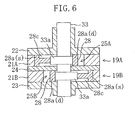
- two cylinders (19A, 19B ) are concentrically disposed.
- the cylinders (19A, 19B ) respectively have the ovoid swing pistons (28, 28) that are the same as in the first embodiment and cylinder chambers (25A, 25B) with conformable configurations with the swing pistons.
- the clearance portions (28c) are formed at the suction side (28a(s)) of each of the swing pistons (28, 28) on the upper surface side of each of the swing pistons (28, 28) and the lower surface side thereof.
- the swing pistons (28, 28) are disposed at positions that the suction side (28a(s)) of one swing piston is phase-shifted by 180° from the suction side (28a(s)) of the other swing piston. Namely, two swing pistons (28, 28) are rotated while their suction sides (28a(s)) always opposing with each other at 180° with respect to a center of rotation of the drive shaft (33) .
- the suction sides (28a(s)) of the swing pistons (28, 28) are disposed so as to oppose with each other with a center of rotation of the drive shaft (33) being interposed therebetween. This relationship is always maintained even if the drive shaft (33) is rotated. Accordingly, the balance of the drive shaft (33) during its rotation is excellent. Thus, as compared to the third embodiment, even further stabilized movement is possible.
- the configurations of the drive shaft (33) and the swing piston (28) are partially changed in the swing compressor of the third embodiment.
- the axial direction length of the eccentric shaft portion (33a) is shorter than that of the cylinder chamber (25) .
- the lower portion of the drive shaft (33) serving as a sub-shaft (33b) has a smaller diameter than the upper portion thereof serving as a main-shaft (33c) .
- a swelling portion (28e) protruding in a radial internal direction is formed at the discharge side (28a(d)) of the swing piston (28) on the surface of the rear head (23).
- the swelling portion (28e) functions as a balance weight during the movement of the swing piston (28).
- the balance weight (28e ) integrally formed with the swing piston (28) is illustrated in the figures, the balance weight (28e) separately formed from the swing piston (28) may be fixed thereto. In that case, the specific gravity and the size of the balance weight (28e) are preferably set depending on the balance of the mass of the swing piston (28) . Alternatively, the balance weight (28e) may be provided at both of the rear head (23) side and the front head (22) side of the swing piston (28) .
- the present invention may be structured as follows.
- the outer peripheral surface of the swing piston (28) is formed in an ovoid shape that a complete round is combined with an ellipse in the first embodiment and in a configuration on a basis of an involute curve in the second embodiment. Nevertheless, the outer peripheral surface of the swing piston (28) may be formed in other configuration as long as a shorter compression cycle and a longer discharge cycle can be obtained as compared to the case of the ovoid shape.
- the cylinder chamber (25) may not be formed in a configuration on a basis of an envelope curve of the configuration of the swing piston (28) .
- the cylinder chamber (25) may be considered to be movable in a relative movement of the swing piston (28) and the cylinder chamber (25) .
- the swing piston (28) may be formed in a configuration on a basis of an envelope curve of the configuration of the cylinder chamber (25) .
- the inner peripheral surface of the cylinder chamber (25) is formed in a non-circular form.
- the outer peripheral surface of the swing piston (28) is formed in a configuration on a basis of an envelope curve of the inner peripheral surface of the cylinder chamber (25) that is obtained by the relative movement thereof when the swing piston (28) is swung.
- the outer peripheral surface of the swing piston (28) and the inner peripheral surface of the cylinder chamber (25) may be formed in configurations that a shorter compression cycle and a longer discharge cycle can be obtained during the movement of the swing piston (28) as compared to the case in which the peripheral surfaces are formed in a circular form.
- the inner peripheral surface of the cylinder chamber (25) may be formed on a basis of an ellipse or an involute curve and the piston (28) may be formed in conformable with the configuration of the cylinder chamber. Also in this case, the same effects as those of the respective embodiments can be exhibited.
- two swing pistons (28) of the second embodiment formed on a basis of an involute curve may be coaxially disposed.
- the swing piston (28) of the second embodiment may be provided with the clearance portion (28c, 28d) and the balance weight (28e) .
- the present invention is useful for a rotary compressor.
Landscapes
- Engineering & Computer Science (AREA)
- Mechanical Engineering (AREA)
- General Engineering & Computer Science (AREA)
- Applications Or Details Of Rotary Compressors (AREA)
- Compressors, Vaccum Pumps And Other Relevant Systems (AREA)
- Supercharger (AREA)
- Control Of Motors That Do Not Use Commutators (AREA)
- Compressor (AREA)
Abstract
Description
- The present invention relates to a rotary compressor, and in particular to, a swing type (piston swing type) rotary compressor that a swing piston is rotated orbitally within a cylinder chamber while a blade which is integrally provided with the swing piston being held by a cylinder and swung.
- A swing compressor with a swing piston has been conventionally known as a rotary compressor as is disclosed in, for example, Japanese Patent Application Laid-Open (JP-A) No. 9-88852. The swing compressor is usually used in order to compress a gas refrigerant in a refrigerant circuit for a refrigerating machine.
- In general, a swing compressor is structured so that its compression mechanism has a schematic horizontal sectional structure as shown in Fig. 8. A compression mechanism (100) comprises a cylinder (102) confining a cylinder chamber (101), a drive shaft (103) disposed so as to penetrate the cylinder chamber (101) and a swing piston (104) which is fitted into an eccentric shaft portion (103a) of the drive shaft (103) and thus accommodated within the cylinder chamber (101). The cylinder chamber (101) is formed so as to have a circular cross-sectional configuration. The drive shaft (103) is disposed concentrically with the cylinder chamber (101). The center of the eccentric shaft portion (103a) is eccentric from the center of the cylinder chamber (101).
- A blade (104a) is formed integrally with the swing piston (104). The blade (104a) is connected via a swing bush pair (105) to the cylinder. Specifically, the swing piston (104) is supported to a free swing about the center of axis of a bush hole (102a) with circular cross-sectional configuration by the blade (104a) being inserted into the bush hole (102a) together with the swing bush pair (105) with substantially semi-circular form with interposed between the pair of swing bushes (105).
- Further, the blade (104a) is supported so as to advance and retreat with respect to the bush pair (105) in the direction of its surface (i.e., in the radial direction of the swing piston (104)). The swing piston (104) is fitted in a free sliding into the eccentric shaft portion (103a) and rotated orbitally along the inner peripheral surface of the cylinder (102) without rotating on its own axis by rotation of the eccentric shaft portion (103a).
- The cylinder chamber (101) is divided, by the swing piston (104) and the blade (104a), into a suction chamber (106) into which a refrigerant with low pressure is suctioned and a compression chamber (107) for compressing a suctioned refrigerant. A suction port (108) communicating with the suction chamber (106) and a discharge port (109) communicating with the compression chamber (107) are formed in the cylinder (102). A discharge valve (110) is attached to the exit of the discharge port (109). The discharge valve (110) is opened when a discharge pressure within the compression chamber (107) reaches a predetermined level.
- In accordance with the swing compressor with the above-described structure, by the eccentric shaft portion (103a) being rotated, the swing piston (104) is rotated orbitally within the cylinder chamber (101) while the blade (104a) is swung, and thus a gas refrigerant suctioned into the cylinder chamber (101) is compressed and discharged by the cylinder chamber volume being varied. Specifically, in accordance with the swing compressor, when a pressure within the cylinder chamber (101) reaches a discharge pressure by a compression cycle performed in the first phase of the orbital movement of the swing piston (104), the differential pressure between inside the cylinder chamber (101) and outside the same reaches a predetermined value, so that the discharge valve (110) is opened. Then, a discharge cycle starts and the refrigerant is discharged.
- A conventional swing compressor has the problem that an overcompression loss for a refrigerant becomes relatively large and thus a compression efficiency is decreased. Causes for this problem are as follows. Namely, in accordance with a conventional swing compressor, the position of the swing piston (104) when the discharge valve (110) is opened is usually positioned slightly over a bottom dead center as illustrated in an imaginary line shown in Fig. 8. The discharge cycle is performed in a relatively narrow angular range from this position to a vicinity of top dead center. Namely, in accordance with a conventional swing compressor, because of this relatively narrow angular range, the discharge cycle is performed in a short time and thus the flow rate of the discharged gas is increased. As a peak pressure is increased, an over compression loss for a refrigerant becomes large. As a result, the efficiency of compressor is decreased.
- The present invention was developed in light of such problems and an object of the present invention is to reduce an overcompression loss generated when a refrigerant is discharged in a swing compressor and thus to prevent a decrease in efficiency.
- In accordance with the present invention, the swing piston (28) and the cylinder chamber (25) are formed in non-circular forms that a longer discharge cycle can be performed, so that over compression is reduced.
- Specifically, in accordance with the inventions recited in Claims 1 and 2, it is presupposed to provide a rotary compressor which comprises a compression mechanism (20) that a swing piston (28) is rotated orbitally within a cylinder chamber (25) while a blade (28b) integrally provided with the swing piston (28) is held by a cylinder (19) and swung.
- In accordance with the rotary compressor of Claim 1, the outer peripheral surface of the swing piston (28) is formed in a non-circular form and the inner peripheral surface of the cylinder chamber (25) is formed on a basis of an envelope curve of the outer peripheral surface of the swing piston (28) at the time of swing of the swing piston (28), and the outer peripheral surface of the swing piston (28) and the inner peripheral surface of the cylinder chamber (25) are formed so that a volume of a suction chamber (25a), which is placed at a suction side with respect to the blade (28b), is larger than a volume of a compression chamber (25b), which is placed at a discharge side with respect to the blade (28b), at a time when the swing piston (28) is placed at a bottom dead center when the swing piston (28) is swinging.
- In accordance with the rotary compressor of Claim 2, the inner peripheral surface of the cylinder chamber (25) is formed in a non-circular form and the outer peripheral surface of the swing piston (28) is formed on a basis of an envelope curve of the inner peripheral surface of the cylinder chamber (25) at the time of swing of the swing piston (28), the outer peripheral surface of the swing piston (28) and the inner peripheral surface of the cylinder chamber (25) are formed so that a volume of a suction chamber (25a), which is placed at a suction side with respect to the blade (28b), is larger than a volume of a compression chamber (25b), which is placed at a discharge side with respect to the blade (28b), at a time when the swing piston (28) is placed at a bottom dead center when the swing piston (28) is swinging.
- In accordance with the inventions of Claims 1 and 2, the blade (28b) integrally formed with the swing piston (28) is held to be swingable by the cylinder (19). Thus, the cylinder chamber (25) is divided into the suction chamber (25a) and the compression chamber (25b) by the blade (28b). When the swing piston (28) is rotated orbitally within the cylinder chamber (25) while the blade (28b) being swung, volumes of the suction chamber (25a) and the compression chamber (25b) are varied. Then, a suction cycle is performed in the suction chamber (25a), and a compression cycle and a discharge cycle are performed in the compression chamber (25b).
- When the suction cycle is completed in the suction chamber (25a) during movement, the suction chamber (25) now becomes the compression chamber (25b) and then the compression cycle starts. Because of the outer peripheral surface of the swing piston (28) and the inner peripheral surface of the cylinder chamber (25) being formed in the above-described configuration, as compared to the case in which such peripheral surfaces are formed in a circular form, the compression cycle ends earlier and the discharge cycle is performed for a longer time. As described above, the discharge cycle is performed for a relatively longer time and thus the flow rate of a discharged gas is decreased. Further, a resistance is also decreased. As a result, overcompression is reduced as compared to the case in which such peripheral surfaces are formed in a circular form.
- In accordance with the invention recited in Claim 3, in the rotary compressor of Claim 1, the outer peripheral surface of the swing piston (28) is formed on a basis of a curved configuration that its suction side (28a(s)) with respect to the blade (28b) is even further protruded radially outward than its discharge side (28a(d)).
- In accordance with the invention recited in Claim 4, in the rotary compressor of Claim 3, the outer peripheral surface of the swing piston (28) is formed so that its discharge side (28a(d)) with respect to the blade (28b) is formed on a basis of a complete round.
- In accordance with the invention recited in Claim 5, in the rotary compressor of Claim 1, the outer peripheral surface of the swing piston (28) is formed on a basis of a spiral configuration so that its diameter is gradually reduced from its suction side (28a(s)) with respect to the blade (28b) to its discharge side (28a(d)).
- In accordance with the invention recited in Claim 6, in the rotary compressor of Claim 5, the outer peripheral surface of the swing piston (28) is formed on a basis of an involute curve.
- In accordance with the inventions recited in Claims 3 to 6, the configuration of the swing piston (28) of the rotary compressor of Claim 1 is specified, and the operation of the rotary compressor relating to Claims 3 to 6 is the same as that of the rotary compressor of Claim 1. Accordingly, as a discharge cycle is performed for a relatively longer time, the flow rate of a discharged gas is decreased and a resistance is also decreased. As a result, overcompression can be suppressed as compared to the case of using a circular swing piston (28).
- In accordance with the invention recited in Claim 7, in the rotary compressor of any one of Claims 3 to 6, the swing piston (28) is provided with a clearance portion (28c, 28d) at its suction side even further protruding than the discharge side (28a(d)).
- In accordance with the invention recited in Claim 8, in the rotary compressor of any one of Claims 3 to 6, the swing piston (28) is provided with a balance weight (28e) at its discharge side (28a(d)) less protruding than the suction side (28a(s)).
- In accordance with the inventions recited in Claims 7 and 8, the suction side (28a(s)) of the swing piston (28) is even further protruded than its discharge side (28(d)). The clearance portion (28c, 28d) is formed at the even further protruding suction side (28a(s)). Alternatively, the balance weight (28e) is formed at the less protruding discharge side (28a(d)). Thus, the suction side (28a(s)) is balanced with the discharge side (28a(d)). Consequently, the rotation of the swing piston (28) is stabilized.
- In accordance with the invention recited in Claim 9, in the rotary compressor of any one of claims 3 to 6, two swing pistons (28, 28) are disposed along a direction of a shaft axis so that their suction sides (28(s)) oppose with each other with respect to the center of the shaft.
- In accordance with the invention recited in Claim 9, two swing pistons (28) are disposed on a shaft so that their suction sides (28a(s)) oppose with each other. Thus, a rotational balance can be obtained and more stable movement can be accomplished.
- As described above, in accordance with the inventions of Claims I and 2, the outer peripheral surface of the swing piston (28) and the inner peripheral surface of the cylinder chamber (25) are formed in non-circular forms so that a volume of a suction chamber (25a), which is placed at a suction side with respect to the blade (28b), is larger than a volume of a compression chamber (25b), which is placed at a discharge side with respect to the blade (28b), at a time when the swing piston (28) is placed at a bottom dead center when the swing piston (28) is swinging. Thus, a compression cycle ends earlier and a discharge cycle is performed for a longer time and overcompression can be suppressed. Further, an increased power loss caused by the overcompression can be prevented and thus a decrease in compression efficiency can be also prevented.
- In accordance with the invention of Claim 3, the swing piston (28) is formed on a basis of a curved configuration such as an ellipse so that its suction side (28a(s)) with respect to the blade (28b) is even further protruded than its discharge side (28a(d)). Thus, overcompression can be suppressed and a decrease in efficiency can be prevented. Even when the swing piston (28) is formed in such configuration, the inner peripheral surface of the cylinder chamber (25) is formed on a basis of an envelope curve obtained at the time of swing of the swing piston (28). Consequently, the movement of the swing piston (28) is ensured.
- In accordance with the invention of Claim 4, the outer peripheral surface of the swing piston (28) is formed so that the discharge side (28a(d)) with respect to the blade (28b) is formed on a basis of a complete round. In the cylinder chamber (25), as the swing piston (28) is swung toward the discharge side, the differential pressure between the suction chamber (25a) and the compression chamber (25b) becomes large, so that a sealing property at the discharge side is required. When the discharge side (28a(d)) is formed in a non-circular form, accuracy of forms of the swing piston (28) and the cylinder chamber (25) are hardly obtained. In contrast, when the discharge side (28a(d)) is formed on a basis of a complete round, required accuracy of forms can be easily obtained and thus the sealing property is improved.
- In accordance with the invention of Claim 5, the outer peripheral surface of the swing piston (28) is formed on a spiral configuration so that its diameter is gradually reduced from the suction side (28a(s)) with respect to the blade (28b) to the discharge side (28a(d)). Also in this case, overcompression can be suppressed as compared to the case of using a circular swing piston. Thus, an increased power loss caused by the overcompression can be prevented and a decrease in compression efficiency can be also prevented.
- In accordance with the invention of Claim 6, the outer peripheral surface of the swing piston (28) is formed on a basis of an involute curve. As the involute curve leads to excellent workability, the required accuracy of form of the overall swing piston (28) is easily obtained. Further, a sealing property is improved.
- In accordance with the invention of Claim 7, the clearance portion (28c, 28d) is formed at the suction side (28a(s)) of the swing piston (28) even further protruding than the discharge side (28a(d)) thereof. Thus, the balanced swing piston (28) can be provided with a simple structure and a stabilized movement can be obtained.
- In accordance with the invention of Claim 8, the balance weight (28e) is provided at the discharge side (28a(d)) of the swing piston (28) less protruding than the suction side (28a(s)). Consequently, the balance of the swing piston (28) can be ensured and a stabilized movement can be obtained.
- In accordance with the invention of Claim 9, two sing pistons (28, 28) on the same shaft are disposed so that their suction sides (28a(s)) oppose with each other with respect to the center of the shaft. Thus, the balance of the swing pistons can be ensured and a more stabilized movement can be performed.
-
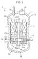
- Fig. 1 is a cross-sectional structural view of a swing compressor relating to an first embodiment of the present invention.
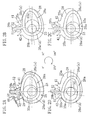
- Figs. 2A to 2D are cross-sectional views illustrating cross-sectional configurations and movement s of a compression mechanism.
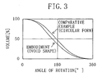
- Fig. 3 is a graph illustrating volume variation of a cylinder chamber in the swing compressor of the first embodiment.
- Figs. 4A to 4D are cross-sectional views illustrating cross-sectional configurations and movements of a compression mechanism in a swing compressor of an second embodiment of the present invention.
- Fig. 5A is a cross-sectional view of a main portion in a swing compressor relating to an third embodiment of the present invention.
- Fig. 5B is a view illustrating the configuration of a swing piston in the swing compressor relating to the third embodiment of the present invention.
- Fig. 5C shows a modified example of Fig. 5B in the swing compressor relating to the third embodiment of the present invention.
- Fig. 6 is a cross-sectional view of a main portion of a swing compressor relating to an fourth embodiment of the present invention.
- Fig. 7A is a cross-sectional view of a main portion of a swing compressor relating to an fifth embodiment of the present invention.
- Fig. 7B is a view illustrating the configuration of a swing piston of the swing compressor relating to the fifth embodiment.
- Fig. 8 is a view illustrating configurations of a cylinder and a swing piston in a conventional swing compressor.
- An first embodiment of the present invention will be described in detail hereinafter with reference to the drawings.
- As shown in Figs. 1 and 2A through 2D, a rotary compressor (1) relating to the first embodiment is a so-called swing compressor. In accordance with the swing compressor (1), a compression mechanism (20) and a compressor motor (30) are accommodated within a casing (10). Further, the swing compressor is structured in a hermetic sealed type. The swing compressor (1) is provided in, for example, a refrigerant circuit for an air conditioning system. The swing compressor (1) suctions a refrigerant, compresses the same and then discharges a compressed refrigerant.
- The casing (10) is formed by a cylindrical trunk portion (11) and end plates (12, 13) respectively fixed to the upper end portion and the lower end portion of the trunk portion (11). A suction pipe (14) penetrating the trunk portion (11) is provided at a predetermined lower position of the trunk portion (11). A discharge pipe (15) communicating the inside of the casing (10) with the outside thereof and a terminal (16) connected to an unillustrated external power source for supplying power to the compressor motor (30) are provided at the upper end plate (12).
- The compression mechanism (20) is disposed at the lower side within the casing (10). The compression mechanism (20) comprises a cylinder (19) and a swing piston (28) which is accommodated within a cylinder chamber (25) of the cylinder (19). The cylinder (19) is formed by an annular cylinder portion (21), a front head (22) closing the upper opening of the cylinder portion (21) and a rear head (23) closing the lower opening of the cylinder portion (21). The cylinder chamber (25) is confined by the inner peripheral surface of the cylinder portion (21), the lower end surface of the front head (22) and the upper end surface of the rear head (23).
- The compressor motor (30) has a stator (31) and a rotor (32). The stator (31) is fixed to the trunk portion (11) of the casing (10) upward of the compression mechanism (20).
- A drive shaft (33) is connected to the rotor (32) and rotates together with the same. The drive shaft (33) vertically penetrates the cylinder chamber (25). Bearing portions (22a, 23a) for supporting the drive shaft (33) are formed in the front head (22) and the rear head (23), respectively.
- An oil supply path (not shown) penetrating the drive shaft (33) in its axial direction is provided in the drive shaft (33). Further, an oil pump (36) is provided at the lower end portion of the drive shaft (33). A lubricant stored in the bottom portion within the casing (10) runs by the oil pump (36) within the oil supply path and supplied to a slide portion of the compression mechanism (20).
- An eccentric shaft portion (33a) is formed at the portion of the drive shaft (33) within the cylinder chamber (25). The eccentric shaft portion (33a) is formed so as to have a larger diameter than other portions of the drive shaft (33) and eccentric by a predetermined amount from the center of axis of the drive shaft (33). The swing piston (28) of the compression mechanism (20) is fitted in a free sliding on the eccentric shaft portion (33a).
- As shown in Figs. 2A through 2D, the swing piston (28) is structured such that an annular main body portion (28a) is integrally formed with a plate-shaped blade (28b) protruding from a position of the outer peripheral surface of the main body portion (28a) and extending toward a radially outside. The blade (28b) and the main body portion (28a) of the swing piston (28) may be formed in an integral part. Alternatively, the blade (28b) and the main body portion (28a) may be separately formed and then integrally fixed with each other. The main body portion (28a) is structured so as to be rotated orbitally within the cylinder chamber (25). The blade (28b) is held to be swingable by the cylinder (19).
- The swing piston (28) has a non-circular outer peripheral surface configuration and is formed in a so-called ovoid shape. The outer peripheral surface of the swing piston (28) is formed so that the right side portion (28a(s)) in the figure with respect to the blade (28b) (i.e., the suction side) is even further protruded as compared to the left side portion (28a(d)) in the figure (i.e., the discharge side) on a basis of a curved surface configuration such as an ellipse. Further, the outer peripheral surface of the swing piston (28) is formed so that the discharge side (28a(d)) with respect to the blade (28b) is formed on a basis of a complete round.
- The swing piston (28) is structured so that the outer peripheral surface of the ovoid main body portion (28a) contacts the inner peripheral surface of the cylinder portion (21) at a point or is adjacent to this point with a minimum clearance therebetween. (In the following description, in order to prevent detailed descriptions, among "contact" and "adjacent", only "contact" will be used.) Unlike the swing piston (28), the inner peripheral surface of the cylinder chamber (25) is not formed in a simple ovoid shape that a complete round is combined with an ellipse but in a configuration on a basis of an envelope curve of the outer peripheral surface of the swing piston (28) when the swing piston (28) swings. Namely, the inner peripheral surface of the cylinder chamber (25) is formed so that especially the portion on the suction side is formed in a deformed curved surface configuration in accordance with the movement of the swing piston (28).
- In other words, the outer peripheral surface of the swing piston (28) and the inner peripheral surface of the cylinder chamber (25) are formed so that in substantially overall areas, their gradients of tangents vary continuously and the gradient of tangent on the swing piston (28) side coincides the gradient of tangent on the cylinder chamber (25) side. "Substantially overall areas" used in such structure means as follows. Namely, in conversely speaking, their gradients of tangents may not vary continuously in areas that do not affect the movement of the swing piston. For example, their gradients of tangents may not continuously vary in an area that does not substantially structure the cylinder chamber (25) such as the area between a suction port (41) and a discharge port (42) to be described later.
- In accordance with one of characteristics of the present invention, the outer peripheral surface of the swing piston (28) and the inner peripheral surface of the cylinder chamber (25) are formed in configurations that as compared to the case in which these outer and inner peripheral surfaces are formed in a simple circular form, a compression cycle at a time of the movement of the swing piston (28) is shorter and a discharge cycle is longer.
- A bush hole (21b) with a circular cross-sectional configuration passes through the cylinder portion (21) so as to be parallel to the axial direction of the drive shaft (33). The bush hole (21b) is formed at the inner peripheral surface side of the cylinder portion (21) so as to communicate with the cylinder chamber (25) at a part in its peripheral direction. A pair of bushes (51, 52) with a substantially semi-circular cross-sectional configuration is inserted into the bush hole (21b). The bushes (51, 52) are formed of a discharge side bush (51) placed at the discharge side of the cylinder chamber (25) and a suction side bush (52) placed at the suction side of the cylinder chamber (25). The blade (28b) of the swing piston (28) is inserted into the bush hole (21b) of the cylinder portion (21) with these bushes (51, 52) being interposed between the hole and the blade.
- The both buses (51, 52) are disposed so that their flat surfaces oppose with each other. The space between these opposing surfaces of the both bushes (52, 52) is formed as a blade groove (29). The blade (28b) of the swing piston (28) is inserted into the blade groove (29). The bushes (51, 52) are formed so that the blade (28b) advances and retreats in the blade groove (29) in the direction of the surface of the blade (28b) while being engaged with the blade groove (29). The bushes (51, 52) are structured so as to swing within the bush hole (21b) integrally with the blade (28b).
- Although the case that the both bushes (51, 52) are separate members is described in this embodiment, the both bushes (51, 52) may be formed integrally.
- When the drive shaft (33) is rotated, the blade (28b) is advanced and retreated within the blade groove (29) and the swing piston (28) is swung with a point on the cylinder side being a center of axis (a center of the bush hole (21b)). By such swing movement, the contact point of the swing piston (28) with the inner peripheral surface of the cylinder portion (21) is successively moved clockwise as shown in Figs. 2A to 2D. At this time, the swing piston (28) (the main portion (28a)) is rotated orbitally about the drive shaft (33) but not rotated on its own axis.
- As shown in Fig. 2C, for example, the blade (28b) divides the cylinder chamber (25) into the suction chamber (25a) and the compression chamber (25b). A suction port (41) is formed in the cylinder portion (21). The suction port (41) penetrates the cylinder portion (21) in a radial direction thereof and is opened so that its one end faces the suction chamber (25a). Connected to the other end of the suction portion (41) is an end portion of the suction pipe (14).
- A discharge port (42) is also formed in the cylinder portion (21). The discharge port (42) penetrates the cylinder portion (21) in a radial direction thereof and is opened so that its one end faces the compression chamber (25b). The other end of the discharge port (42) communicates with a discharge space within the casing (10) via a discharge valve (46) for opening/closing the discharge port (42) (see Fig. 2A).
- Next, the operation of the swing compressor (1) will be described.
- When the compressor motor (30) is activated and the rotor (32) is rotated, the rotation of the rotor (32) is transmitted via the drive shaft (33) to the swing piston (28) of the compression mechanism (20). Then, the blade (28b) of the swing piston (28) slides with respect to the bushes (51, 52) as a reciprocating linear movement, and the bushes (51, 52) are reciprocally rotated within the bush hole (21b). As a result, in the swing piston (28), the blade (28b) is swung about the bush hole (21b) and the main body portion (28a) is rotated orbitally about the drive shaft (33) within the cylinder chamber (25). Then, the compression mechanism (20) performs a predetermined compression movement.
- Specifically, as shown in Fig. 2B, a description will be firstly given of the state that the inner peripheral surface of the cylinder portion (21) contacts the outer peripheral surface of the swing piston (28) at a point on the immediate right side of the suction port (41).
- Under such state, the volume of the suction chamber (25a) of the cylinder chamber (25) is approximately minimized. When the swing piston (28) is rotated orbitally clockwise in the figure, the volume of the suction chamber (25a) is gradually increased and a gas refrigerant with low pressure is suctioned via the suction port (41) into the suction chamber (25a). In accordance with this suction cycle, when the swing piston (28) is placed at a bottom dead center as shown in Fig. 2C, the volume of the suction chamber (25a) is larger than that of the compression chamber (25b).
- When the swing piston (28) continues to be rotated orbitally, the volume of the suction chamber (25a) is further increased and the contact position of the inner peripheral surface of the cylinder portion (21) with the outer peripheral surface of the swing piston (28) reaches the suction port (41), the suction chamber (25a) now becomes the compression chamber (25b) for compressing a refrigerant. Then, a new suction chamber (25a) is formed by being isolated by the blade (28b).
- When the swing piston (28) is further rotated, the volume of the compression chamber (25b) is reduced while a refrigerant being repeatedly suctioned into the suction chamber (25a). In the compression chamber (25b), the refrigerant is compressed. When the pressure within the compression chamber (25b) reaches a predetermined value and the differential pressure between the outside of the compression mechanism (20) and the inside thereof reaches a set value, the discharge valve (46) is opened by a refrigerant with high pressure and the refrigerant with high pressure is discharged from the compression chamber (25b) into the casing (10). Such movements are repeated.
- In accordance with the first embodiment, as described above, when the swing piston (28) is placed at a bottom dead center as shown in Fig. 2C, the volume of the suction chamber (25a) is larger than that of the compression chamber (25b). Accordingly, as shown in Fig. 3 that illustrates variations of the volume of the cylinder chamber, in the case of a comparative example that the swing piston (28) has a circular form, 50% of volume variation is obtained substantially at the position of bottom dead center (180°). On the other hand, in the case of this first embodiment that the swing piston (28) has an ovoid shape, 50% of volume variation is obtained well before reaching the bottom dead center.
- Thus, in accordance with this embodiment, the pressure within the compression chamber (25b) reaches a discharge pressure earlier as compared to the comparative example. For this reason, a discharge cycle is performed for a longer time as compared to the comparative example. Further, as the discharge cycle is performed for a relatively long time, the flow rate of a discharged gas is decreased and a discharge resistance is also decreased. Consequently, in accordance with the first embodiment, as compared to the case that a circular swing piston is used, a peak pressure is decreased and overcompression of a refrigerant seldom occurs.
- As described above, in accordance with the first embodiment, the outer peripheral surface of the swing piston (28) is formed in a non-circular form and the inner peripheral surface of the cylinder chamber (25) is formed in a conformable configuration with the outer peripheral surface. Namely, the outer peripheral surface and the inner peripheral surface are formed in configurations that a compression cycle ends earlier and a discharge cycle is performed for a longer time as compared to the case in which these surfaces are formed in a circular form. Thus, overcompression of a refrigerant is suppressed and a power loss can be minimized. As a result, a decrease in a compression efficiency can be prevented.
- In accordance with the first embodiment, the inner peripheral surface of the cylinder chamber (25) is formed on a basis of an envelope curve obtained when the swing piston (28) is swung. In contrast, for example, when the inner peripheral surface of the cylinder chamber (25) is formed in a configuration that a complete round is combined with an ellipse as the outer peripheral surface of the piston (28), portions that a gradient of tangent of elliptical portion of the swing piston (28) does not coincide that of the cylinder chamber (25) when the swing piston(28) is swung may be generated. Thus, sealing is impossible and the compressor cannot be operated. In accordance with this embodiment, however, as the cylinder chamber (25) is formed in the above-described configuration, the swing piston (28) can be smoothly operated and an excellent sealing property can be ensured.
- Further, in accordance with the first embodiment, the outer peripheral surface of the swing piston (28) on the discharge side with respect to the blade (28b) is formed on a basis of a complete round. Generally, in the cylinder chamber (25), as the swing piston (28) is moved to the discharge side (e.g., the state shown in Fig. 2D), the differential pressure between the suction chamber (25a) and the compression chamber (25b) becomes larger and thus a sealing property is much required. If the outer peripheral surface of the swing piston (28) on the discharge side is formed in a non-circular form, accuracy of forms of the swing piston (28) and the cylinder chamber (25) cannot be obtained easily and thus a sealing property is apt to be decreased. In contrast, in accordance with the first embodiment, the outer peripheral surface of the swing piston (28) on the discharge side is formed in a complete round configuration, required accuracy of form can be easily obtained and a sealing property can be improved.
- If the overall swing piston (28) is formed in a circular form, as compared to the first embodiment, a discharge cycle becomes shorter and the flow rate of a discharged gas is increased and thus a peak pressure is also increased. Further, the pulsating of discharge pressure becomes relatively large, torque variations and vibrations become larger and noises are easily generated. In contrast, in accordance with the first embodiment, such problems can be solved. Namely, torque variations, vibrations and noises can be suppressed.
- Next, a second embodiment of the present invention will be described. In accordance with the second embodiment, as shown in Fig. 4, the outer peripheral surface of the swing piston (28) and the inner peripheral surface of the cylinder chamber (25) are formed in different configurations from those of the first embodiment.
- The outer peripheral surface of the swing piston (28) of the second embodiment is formed on a basis of a spiral configuration such as an involute curve so that the radius of the swing piston (28) is reduced from the suction side (28a(s)) with respect to the blade (28d) to the discharge side (28a(d)).
- The inner peripheral surface of the cylinder chamber (25) is formed in a configuration that a gradient obtained by the swing movement of the swing piston (28) is added into an involute curve. Namely, also in this embodiment, the inner peripheral surface of the cylinder chamber (25) is formed on a basis of an envelope curve obtained when the swing piston is swung.
- In accordance with the second embodiment, the width of the surface of the blade (28b) on the suction side (i.e., the length of the blade (28b) in the radial direction of the swing piston (28)) is shorter than that of the surface on the discharge side. For this reason, the dimensional different between such surfaces is absorbed by using bushes (51, 52) with different diameters. Further, a spacer (27) is mounted between the eccentric shaft portion (33a) and the main body portion (28a) of the swing piston (28) so as to be embedded into the space therebetween. The spacer (27) may be formed integrally with the main body portion of the swing piston (28) or may be formed separately therefrom. In this regard, the second embodiment is the same as the first embodiment.
- Other structures of the second embodiment are the same as those of the first embodiment.
- In accordance with the second embodiment, when the compressor motor (30) is activated, in accordance with the drive shaft (33) being rotated, the blade (28b) is advanced and retreated within the blade groove (29) while being swung about the bushes (51, 52) and the main body portion (28a) of the swing piston (28) is rotated orbitally about the drive shaft (33) as shown in Figs. 4A to 4D.
- In the cylinder chamber (25), suction of a refrigerant at the suction chamber (25a) and compression/discharge of the refrigerant at the compression chamber (25b) are repeated, and the compressor is operated by the same manner as that of the first embodiment.
- Also, in accordance with the second embodiment, as shown in Fig. 4C, the volume of the suction chamber (25a) is larger than that of the compression chamber (25b) when the swing piston (28) reaches a bottom dead center. Accordingly, as compared to the case of a circular swing piston, a compression cycle ends earlier and a discharge cycle is performed for a longer time. For this reason, as in the first embodiment, the flow rate of a discharged gas is decreased and a resistance is also decreased, so that overcompression is reduced as compared to the case of using a circular swing piston. As a result, as compared to conventional examples, a power loss can be minimized and a decrease in a compression efficiency can be prevented. Namely, an improvement in performance can be accomplished.
- By the swing piston (28) being formed along an involute curve, working for the piston can be easily performed as compared to an ovoid piston.
- Next, a third embodiment of the present invention will be described.
- A swing compressor of the third embodiment has the same basic structure as the swing compressor (1) of the first embodiment except for a part of the swing piston (28). Thus, descriptions of other portions except for the swing piston (28) will be omitted in the third embodiment.
- As shown in Figs. 5A and 5B, clearance portions (28c) are formed by counter boring on surfaces of the swing piston (28) of the third embodiment on the front head (22) side and the rear head (23) side. Each clearance portion (28c) is formed at the suction side (28a(s)) of the swing piston (28) even further protruding than the discharge side (28a(d)) thereof and not formed at the discharge side (28a(d)).
- Although materials for the swing piston (28) are not specified in the above-described embodiments, metallic materials with small specific gravity including an aluminum with smaller specific gravity than steel materials used for the drive shaft (33) or synthetic resin materials are used for the swing piston (28) of the third embodiment. Such materials may be used in the embodiments 1 and 2.
- In accordance with the third embodiment, in addition to that a cycle for discharging a refrigerant is extended by the same actions as in the first embodiment and thus overcompression is suppressed, by reducing the specific gravity of the swing piston (28) and forming the clearance portion (28c), the balance of the swing piston (28) during its movement is improved and a stable movement is possible.
- Fig. 5C shows a modified example of the third embodiment.
- In accordance with this example, a through-hole (28d) as well as the counter borings (28c) is formed as the clearance portion (28c) at the suction side (28a(s)) of the swing piston (28) even further protruding than the discharge side (28a(d)). Other structures are the same as in the examples shown in Figs. 5A and 5B.
- Because of such structure, the mass of the suction side (28a(s)) of the swing piston (28) becomes even further smaller and thus stability of movement during the operation of the compressor can be further improved.
- Next, an fourth embodiment of the present invention will be described.
- In accordance with the fourth embodiment, as shown in Fig. 6, two cylinders (19A, 19B) are concentrically disposed. The cylinders (19A, 19B) respectively have the ovoid swing pistons (28, 28) that are the same as in the first embodiment and cylinder chambers (25A, 25B) with conformable configurations with the swing pistons. The clearance portions (28c) are formed at the suction side (28a(s)) of each of the swing pistons (28, 28) on the upper surface side of each of the swing pistons (28, 28) and the lower surface side thereof.
- In accordance with one of characteristics of the present invention, the swing pistons (28, 28) are disposed at positions that the suction side (28a(s)) of one swing piston is phase-shifted by 180° from the suction side (28a(s)) of the other swing piston. Namely, two swing pistons (28, 28) are rotated while their suction sides (28a(s)) always opposing with each other at 180° with respect to a center of rotation of the drive shaft (33).
- Other portions have the same structures as in the above-described embodiments.
- In accordance with the fourth embodiment, the suction sides (28a(s)) of the swing pistons (28, 28) are disposed so as to oppose with each other with a center of rotation of the drive shaft (33) being interposed therebetween. This relationship is always maintained even if the drive shaft (33) is rotated. Accordingly, the balance of the drive shaft (33) during its rotation is excellent. Thus, as compared to the third embodiment, even further stabilized movement is possible.
- Next, an fifth embodiment of the present invention will be described.
- In accordance with the fifth embodiment, the configurations of the drive shaft (33) and the swing piston (28) are partially changed in the swing compressor of the third embodiment.
- Specifically, as shown in Figs. 7A and 7B, the axial direction length of the eccentric shaft portion (33a) is shorter than that of the cylinder chamber (25). Further, the lower portion of the drive shaft (33) serving as a sub-shaft (33b) has a smaller diameter than the upper portion thereof serving as a main-shaft (33c). A swelling portion (28e) protruding in a radial internal direction is formed at the discharge side (28a(d)) of the swing piston (28) on the surface of the rear head (23). The swelling portion (28e) functions as a balance weight during the movement of the swing piston (28).
- When the same operations as in the third embodiment shown in Figs. 5A to 5C are performed in the fifth embodiment, the movement of the swing piston (28) is even further stabilized because of the balance weight (28e). Accordingly, more stable movement of the swing compressor (1) can be accomplished.
- Although the balance weight (28e) integrally formed with the swing piston (28) is illustrated in the figures, the balance weight (28e) separately formed from the swing piston (28) may be fixed thereto. In that case, the specific gravity and the size of the balance weight (28e) are preferably set depending on the balance of the mass of the swing piston (28). Alternatively, the balance weight (28e) may be provided at both of the rear head (23) side and the front head (22) side of the swing piston (28).
- For the above-described embodiments, the present invention may be structured as follows.
- The outer peripheral surface of the swing piston (28) is formed in an ovoid shape that a complete round is combined with an ellipse in the first embodiment and in a configuration on a basis of an involute curve in the second embodiment. Nevertheless, the outer peripheral surface of the swing piston (28) may be formed in other configuration as long as a shorter compression cycle and a longer discharge cycle can be obtained as compared to the case of the ovoid shape.
- Further, the cylinder chamber (25) may not be formed in a configuration on a basis of an envelope curve of the configuration of the swing piston (28). The cylinder chamber (25) may be considered to be movable in a relative movement of the swing piston (28) and the cylinder chamber (25). Then, the swing piston (28) may be formed in a configuration on a basis of an envelope curve of the configuration of the cylinder chamber (25).
- The inner peripheral surface of the cylinder chamber (25) is formed in a non-circular form. Then, the outer peripheral surface of the swing piston (28) is formed in a configuration on a basis of an envelope curve of the inner peripheral surface of the cylinder chamber (25) that is obtained by the relative movement thereof when the swing piston (28) is swung. Thus, the outer peripheral surface of the swing piston (28) and the inner peripheral surface of the cylinder chamber (25) may be formed in configurations that a shorter compression cycle and a longer discharge cycle can be obtained during the movement of the swing piston (28) as compared to the case in which the peripheral surfaces are formed in a circular form.
- Consequently, the inner peripheral surface of the cylinder chamber (25) may be formed on a basis of an ellipse or an involute curve and the piston (28) may be formed in conformable with the configuration of the cylinder chamber. Also in this case, the same effects as those of the respective embodiments can be exhibited.
- Moreover, two swing pistons (28) of the second embodiment formed on a basis of an involute curve may be coaxially disposed. The swing piston (28) of the second embodiment may be provided with the clearance portion (28c, 28d) and the balance weight (28e).
- As described above, the present invention is useful for a rotary compressor.
Claims (9)
- A rotary compressor comprising a compression mechanism (20) that a swing piston (28) is rotated orbitally within a cylinder chamber (25) while a blade (28b) integrally provided with the swing piston (28) is held by a cylinder (19) and swung,
characterized in that the outer peripheral surface of the swing piston (28) is formed in a non-circular form and the inner peripheral surface of the cylinder chamber (25) is formed on a basis of an envelope curve of the outer peripheral surface of the swing piston (28) at the time of swing of the swing piston (28), and
the outer peripheral surface of the swing piston (28) and the inner peripheral surface of the cylinder chamber (25) are formed so that a volume of a suction chamber (25a), which is placed at a suction side with respect to the blade (28b), is larger than a volume of a compression chamber (25b), which is placed at a discharge side with respect to the blade (28b), at a time when the swing piston (28) is placed at a bottom dead center when the swing piston (28) is swinging. - A rotary compressor comprising a compression mechanism (20) that a swing piston (28) is rotated orbitally within a cylinder chamber (25) while a blade (28b) integrally provided with the swing piston (28) is held by a cylinder (19) and swung,
characterized in that the inner peripheral surface of the cylinder chamber (25) is formed in a non-circular form and the outer peripheral surface of the swing piston (28) is formed on a basis of an envelope curve of the inner peripheral surface of the cylinder chamber (25) at the time of swing of the swing piston (28),
the outer peripheral surface of the swing piston (28) and the inner peripheral surface of the cylinder chamber (25) are formed so that a volume of a suction chamber (25a), which is placed at a suction side with respect to the blade (28b), is larger than a volume of a compression chamber (25b) which is placed at a discharge side with respect to the blade (28b), at a time when the swing piston (28) is placed at a bottom dead center when the swing piston (28) is swinging. - The rotary compressor of Claim 1, wherein the outer peripheral surface of the swing piston (28) is formed on a basis of a curved surface configuration that its suction side (28a(s)) with respect to the blade (28b) is even further protruded radially outward than its discharge side (28a(d)).
- The rotary compressor of Claim 3, wherein the outer peripheral surface of the swing piston (28) is formed so that its discharge side (28a(d)) with respect to the blade (28b) is formed on a basis of a complete round.
- The rotary compressor of Claim 1, wherein the outer peripheral surface of the swing piston (28) is formed on a basis of a spiral configuration so that its diameter is gradually reduced from its suction side (28a(s)) with respect to the blade (28b) to its discharge side (28a(d)).
- The rotary compressor of Claim 5, wherein the outer peripheral surface of the swing piston (28) is formed on a basis of an involute curve.
- The rotary compressor of any one of Claims 3 to 6, wherein the swing piston (28) is provided with a clearance portion (28c, 28d) at its suction side even further protruding than the discharge side (28a(d)).
- The rotary compressor of any one of Claims 3 to 6, wherein the swing piston (28) is provided with a balance weight (28e) at its discharge side (28a(d)) less protruding than the suction side (28a(s)).
- The rotary compressor of any one of Claims 3 to 6, wherein two swing pistons (28, 28) are disposed along a direction of a shaft axis so that their suction sides (28(s)) oppose with each other with respect to the center of the shaft.
Applications Claiming Priority (3)
| Application Number | Priority Date | Filing Date | Title |
|---|---|---|---|
| JP2002074052 | 2002-03-18 | ||
| JP2002074052A JP4385565B2 (en) | 2002-03-18 | 2002-03-18 | Rotary compressor |
| PCT/JP2003/001998 WO2003078842A1 (en) | 2002-03-18 | 2003-02-24 | Rotary compressor |
Publications (3)
| Publication Number | Publication Date |
|---|---|
| EP1486677A1 EP1486677A1 (en) | 2004-12-15 |
| EP1486677A4 EP1486677A4 (en) | 2005-12-28 |
| EP1486677B1 true EP1486677B1 (en) | 2007-02-21 |
Family
ID=28035280
Family Applications (1)
| Application Number | Title | Priority Date | Filing Date |
|---|---|---|---|
| EP03707027A Expired - Lifetime EP1486677B1 (en) | 2002-03-18 | 2003-02-24 | Rotary compressor |
Country Status (11)
| Country | Link |
|---|---|
| US (1) | US7029252B2 (en) |
| EP (1) | EP1486677B1 (en) |
| JP (1) | JP4385565B2 (en) |
| KR (1) | KR100522840B1 (en) |
| CN (1) | CN100400879C (en) |
| AT (1) | ATE354731T1 (en) |
| DE (1) | DE60311970D1 (en) |
| ES (1) | ES2282605T3 (en) |
| MY (1) | MY129366A (en) |
| TW (1) | TW571028B (en) |
| WO (1) | WO2003078842A1 (en) |
Families Citing this family (21)
| Publication number | Priority date | Publication date | Assignee | Title |
|---|---|---|---|---|
| EP1757812A4 (en) * | 2004-04-23 | 2012-05-02 | Daikin Ind Ltd | Rotating fluid machine |
| TWI274105B (en) * | 2005-01-20 | 2007-02-21 | Hitachi Ltd | Portable vacuum pump and automatic urination treatment apparatus using thereof |
| JP5017842B2 (en) * | 2005-10-20 | 2012-09-05 | ダイキン工業株式会社 | Rotary compressor |
| JP4978461B2 (en) * | 2007-12-27 | 2012-07-18 | ダイキン工業株式会社 | Rotary compressor |
| JP2009222329A (en) * | 2008-03-18 | 2009-10-01 | Daikin Ind Ltd | Refrigerating device |
| KR101487022B1 (en) | 2008-07-22 | 2015-01-29 | 엘지전자 주식회사 | Compressor |
| US8636480B2 (en) * | 2008-07-22 | 2014-01-28 | Lg Electronics Inc. | Compressor |
| CN102459910B (en) * | 2009-06-16 | 2015-03-11 | 大金工业株式会社 | Rotary compressor |
| US8794941B2 (en) | 2010-08-30 | 2014-08-05 | Oscomp Systems Inc. | Compressor with liquid injection cooling |
| US9267504B2 (en) | 2010-08-30 | 2016-02-23 | Hicor Technologies, Inc. | Compressor with liquid injection cooling |
| JP2013139725A (en) * | 2011-12-28 | 2013-07-18 | Daikin Industries Ltd | Oscillating piston type compressor |
| JP5929189B2 (en) * | 2011-12-28 | 2016-06-01 | ダイキン工業株式会社 | Swing piston compressor |
| JP5861458B2 (en) * | 2011-12-28 | 2016-02-16 | ダイキン工業株式会社 | Swing piston compressor |
| JP2013139724A (en) * | 2011-12-28 | 2013-07-18 | Daikin Industries Ltd | Oscillating piston type compressor |
| JP6127722B2 (en) * | 2012-05-28 | 2017-05-17 | ダイキン工業株式会社 | Rotary compressor |
| JP2014005775A (en) * | 2012-06-25 | 2014-01-16 | Nippon Soken Inc | Compressor |
| WO2017146167A1 (en) * | 2016-02-23 | 2017-08-31 | ダイキン工業株式会社 | Oscillating piston-type compressor |
| CN106089706B (en) * | 2016-08-15 | 2018-03-30 | 珠海格力节能环保制冷技术研究中心有限公司 | Rotary type compressor pump body provided therewith component and rotary compressor |
| JP6930576B2 (en) * | 2019-12-17 | 2021-09-01 | ダイキン工業株式会社 | Compressor |
| DE102020117343A1 (en) * | 2020-07-01 | 2022-01-05 | Weinmann Emergency Medical Technology Gmbh + Co. Kg | Pump device, device for ventilation and method for providing a breathing gas |
| DE102022132001B3 (en) | 2022-12-02 | 2024-04-25 | Schaeffler Technologies AG & Co. KG | Oscillating piston compressor |
Family Cites Families (17)
| Publication number | Priority date | Publication date | Assignee | Title |
|---|---|---|---|---|
| FR1238461A (en) * | 1959-07-03 | 1960-08-12 | Rotary machine without internal lubrication for the suction and delivery of a fluid | |
| JPS59147893A (en) * | 1983-02-14 | 1984-08-24 | Nippon Soken Inc | Ring type pump |
| JPS649167A (en) * | 1987-07-01 | 1989-01-12 | Kotobukiya Goushi | Lidded box having medicine case lid and preparation thereof |
| CN1065123A (en) * | 1991-03-20 | 1992-10-07 | 杨中杰 | Triangular rotary machinery |
| JPH05248381A (en) * | 1992-03-05 | 1993-09-24 | Daikin Ind Ltd | Rotary compressor |
| JPH05248382A (en) * | 1992-03-05 | 1993-09-24 | Daikin Ind Ltd | Rotary compressor |
| DK0591539T3 (en) * | 1992-04-28 | 1999-05-10 | Daikin Ind Ltd | Rotary compressor in which blade and roller are integrated |
| JPH05312171A (en) * | 1992-05-08 | 1993-11-22 | Daikin Ind Ltd | Rolling piston type compressor |
| JP2770648B2 (en) | 1992-05-11 | 1998-07-02 | ダイキン工業株式会社 | Rotary compressor |
| WO1994024492A1 (en) * | 1993-04-09 | 1994-10-27 | Daikin Industries, Ltd. | Operation control device for an air conditioning device |
| JP3473066B2 (en) * | 1993-12-06 | 2003-12-02 | ダイキン工業株式会社 | Swing type rotary compressor |
| JP3622216B2 (en) * | 1993-12-24 | 2005-02-23 | ダイキン工業株式会社 | Swing type rotary compressor |
| JPH0988852A (en) | 1995-09-18 | 1997-03-31 | Daikin Ind Ltd | Swing compressor |
| JPH0988856A (en) * | 1995-09-20 | 1997-03-31 | Daikin Ind Ltd | Rotary compressor |
| JPH109167A (en) * | 1996-06-20 | 1998-01-13 | Hitachi Ltd | Rotary compressor |
| JP2000027772A (en) * | 1998-07-08 | 2000-01-25 | Matsushita Electric Ind Co Ltd | Hermetic compressor |
| JP2001254688A (en) * | 2000-03-08 | 2001-09-21 | Hitachi Ltd | Swinging piston type compressor and freezer using it |
-
2002
- 2002-03-18 JP JP2002074052A patent/JP4385565B2/en not_active Expired - Fee Related
-
2003
- 2003-02-24 DE DE60311970T patent/DE60311970D1/en not_active Expired - Fee Related
- 2003-02-24 WO PCT/JP2003/001998 patent/WO2003078842A1/en active IP Right Grant
- 2003-02-24 KR KR10-2003-7015038A patent/KR100522840B1/en not_active IP Right Cessation
- 2003-02-24 EP EP03707027A patent/EP1486677B1/en not_active Expired - Lifetime
- 2003-02-24 US US10/467,279 patent/US7029252B2/en not_active Expired - Lifetime
- 2003-02-24 CN CNB038002531A patent/CN100400879C/en not_active Expired - Fee Related
- 2003-02-24 ES ES03707027T patent/ES2282605T3/en not_active Expired - Lifetime
- 2003-02-24 AT AT03707027T patent/ATE354731T1/en not_active IP Right Cessation
- 2003-03-17 MY MYPI20030916A patent/MY129366A/en unknown
- 2003-03-18 TW TW092105900A patent/TW571028B/en not_active IP Right Cessation
Also Published As
| Publication number | Publication date |
|---|---|
| TW571028B (en) | 2004-01-11 |
| CN1509378A (en) | 2004-06-30 |
| KR20030096413A (en) | 2003-12-24 |
| TW200305688A (en) | 2003-11-01 |
| MY129366A (en) | 2007-03-30 |
| EP1486677A1 (en) | 2004-12-15 |
| US7029252B2 (en) | 2006-04-18 |
| EP1486677A4 (en) | 2005-12-28 |
| JP2003269348A (en) | 2003-09-25 |
| ATE354731T1 (en) | 2007-03-15 |
| JP4385565B2 (en) | 2009-12-16 |
| ES2282605T3 (en) | 2007-10-16 |
| WO2003078842A1 (en) | 2003-09-25 |
| CN100400879C (en) | 2008-07-09 |
| DE60311970D1 (en) | 2007-04-05 |
| KR100522840B1 (en) | 2005-10-19 |
| US20050008519A1 (en) | 2005-01-13 |
Similar Documents
| Publication | Publication Date | Title |
|---|---|---|
| EP1486677B1 (en) | Rotary compressor | |
| US7802972B2 (en) | Rotary type compressor | |
| KR100315791B1 (en) | Scroll Compressor | |
| US8366424B2 (en) | Rotary fluid machine with reverse moment generating mechanism | |
| KR100315954B1 (en) | Compressor | |
| JP3142890B2 (en) | Fluid compressor | |
| JP5217818B2 (en) | Rotary compressor | |
| KR100679883B1 (en) | A hermetic type orbiter compressor | |
| JP4858047B2 (en) | Compressor | |
| JP4887790B2 (en) | Rotary fluid machine | |
| JP3972149B2 (en) | Rotary compressor | |
| JP3742849B2 (en) | Rotary compressor | |
| JPS62178794A (en) | Scroll compressor | |
| JP3347050B2 (en) | Helical blade compressor | |
| JP4830708B2 (en) | Compressor | |
| JP4635819B2 (en) | Rotary compressor | |
| JP2006170213A5 (en) | ||
| JP5018008B2 (en) | Rotary fluid machine | |
| JP4807209B2 (en) | Compressor | |
| JP3744526B2 (en) | Rotary compressor | |
| JPH1047278A (en) | Swing compressor | |
| KR20230136822A (en) | Automotive Orbiter Compressor | |
| JP4929951B2 (en) | Rotary compressor | |
| JP5011963B2 (en) | Rotary fluid machine | |
| JP2880771B2 (en) | Fluid compressor |
Legal Events
| Date | Code | Title | Description |
|---|---|---|---|
| PUAI | Public reference made under article 153(3) epc to a published international application that has entered the european phase |
Free format text: ORIGINAL CODE: 0009012 |
|
| 17P | Request for examination filed |
Effective date: 20030729 |
|
| AK | Designated contracting states |
Kind code of ref document: A1 Designated state(s): AT BE BG CH CY CZ DE DK EE ES FI FR GB GR HU IE IT LI LU MC NL PT SE SI SK TR |
|
| A4 | Supplementary search report drawn up and despatched |
Effective date: 20051114 |
|
| GRAP | Despatch of communication of intention to grant a patent |
Free format text: ORIGINAL CODE: EPIDOSNIGR1 |
|
| GRAS | Grant fee paid |
Free format text: ORIGINAL CODE: EPIDOSNIGR3 |
|
| RTI1 | Title (correction) |
Free format text: ROTARY COMPRESSOR |
|
| GRAA | (expected) grant |
Free format text: ORIGINAL CODE: 0009210 |
|
| AK | Designated contracting states |
Kind code of ref document: B1 Designated state(s): AT BE BG CH CY CZ DE DK EE ES FI FR GB GR HU IE IT LI LU MC NL PT SE SI SK TR |
|
| PG25 | Lapsed in a contracting state [announced via postgrant information from national office to epo] |
Ref country code: CH Free format text: LAPSE BECAUSE OF FAILURE TO SUBMIT A TRANSLATION OF THE DESCRIPTION OR TO PAY THE FEE WITHIN THE PRESCRIBED TIME-LIMIT Effective date: 20070221 Ref country code: SI Free format text: LAPSE BECAUSE OF FAILURE TO SUBMIT A TRANSLATION OF THE DESCRIPTION OR TO PAY THE FEE WITHIN THE PRESCRIBED TIME-LIMIT Effective date: 20070221 Ref country code: FI Free format text: LAPSE BECAUSE OF FAILURE TO SUBMIT A TRANSLATION OF THE DESCRIPTION OR TO PAY THE FEE WITHIN THE PRESCRIBED TIME-LIMIT Effective date: 20070221 Ref country code: NL Free format text: LAPSE BECAUSE OF FAILURE TO SUBMIT A TRANSLATION OF THE DESCRIPTION OR TO PAY THE FEE WITHIN THE PRESCRIBED TIME-LIMIT Effective date: 20070221 Ref country code: AT Free format text: LAPSE BECAUSE OF FAILURE TO SUBMIT A TRANSLATION OF THE DESCRIPTION OR TO PAY THE FEE WITHIN THE PRESCRIBED TIME-LIMIT Effective date: 20070221 Ref country code: DK Free format text: LAPSE BECAUSE OF FAILURE TO SUBMIT A TRANSLATION OF THE DESCRIPTION OR TO PAY THE FEE WITHIN THE PRESCRIBED TIME-LIMIT Effective date: 20070221 Ref country code: LI Free format text: LAPSE BECAUSE OF FAILURE TO SUBMIT A TRANSLATION OF THE DESCRIPTION OR TO PAY THE FEE WITHIN THE PRESCRIBED TIME-LIMIT Effective date: 20070221 |
|
| REG | Reference to a national code |
Ref country code: GB Ref legal event code: FG4D |
|
| PG25 | Lapsed in a contracting state [announced via postgrant information from national office to epo] |
Ref country code: MC Free format text: LAPSE BECAUSE OF NON-PAYMENT OF DUE FEES Effective date: 20070228 |
|
| REG | Reference to a national code |
Ref country code: CH Ref legal event code: EP |
|
| REF | Corresponds to: |
Ref document number: 60311970 Country of ref document: DE Date of ref document: 20070405 Kind code of ref document: P |
|
| REG | Reference to a national code |
Ref country code: IE Ref legal event code: FG4D |
|
| PG25 | Lapsed in a contracting state [announced via postgrant information from national office to epo] |
Ref country code: SE Free format text: LAPSE BECAUSE OF FAILURE TO SUBMIT A TRANSLATION OF THE DESCRIPTION OR TO PAY THE FEE WITHIN THE PRESCRIBED TIME-LIMIT Effective date: 20070521 |
|
| PG25 | Lapsed in a contracting state [announced via postgrant information from national office to epo] |
Ref country code: BG Free format text: LAPSE BECAUSE OF EXPIRATION OF PROTECTION Effective date: 20070522 |
|
| PG25 | Lapsed in a contracting state [announced via postgrant information from national office to epo] |
Ref country code: PT Free format text: LAPSE BECAUSE OF FAILURE TO SUBMIT A TRANSLATION OF THE DESCRIPTION OR TO PAY THE FEE WITHIN THE PRESCRIBED TIME-LIMIT Effective date: 20070723 |
|
| NLV1 | Nl: lapsed or annulled due to failure to fulfill the requirements of art. 29p and 29m of the patents act | ||
| REG | Reference to a national code |
Ref country code: CH Ref legal event code: PL |
|
| EN | Fr: translation not filed | ||
| REG | Reference to a national code |
Ref country code: ES Ref legal event code: FG2A Ref document number: 2282605 Country of ref document: ES Kind code of ref document: T3 |
|
| PG25 | Lapsed in a contracting state [announced via postgrant information from national office to epo] |
Ref country code: SK Free format text: LAPSE BECAUSE OF FAILURE TO SUBMIT A TRANSLATION OF THE DESCRIPTION OR TO PAY THE FEE WITHIN THE PRESCRIBED TIME-LIMIT Effective date: 20070221 |
|
| PLBE | No opposition filed within time limit |
Free format text: ORIGINAL CODE: 0009261 |
|
| STAA | Information on the status of an ep patent application or granted ep patent |
Free format text: STATUS: NO OPPOSITION FILED WITHIN TIME LIMIT |
|
| PG25 | Lapsed in a contracting state [announced via postgrant information from national office to epo] |
Ref country code: CZ Free format text: LAPSE BECAUSE OF FAILURE TO SUBMIT A TRANSLATION OF THE DESCRIPTION OR TO PAY THE FEE WITHIN THE PRESCRIBED TIME-LIMIT Effective date: 20070221 |
|
| 26N | No opposition filed |
Effective date: 20071122 |
|
| GBPC | Gb: european patent ceased through non-payment of renewal fee |
Effective date: 20070521 |
|
| PG25 | Lapsed in a contracting state [announced via postgrant information from national office to epo] |
Ref country code: IE Free format text: LAPSE BECAUSE OF NON-PAYMENT OF DUE FEES Effective date: 20070226 Ref country code: DE Free format text: LAPSE BECAUSE OF NON-PAYMENT OF DUE FEES Effective date: 20070901 |
|
| PG25 | Lapsed in a contracting state [announced via postgrant information from national office to epo] |
Ref country code: FR Free format text: LAPSE BECAUSE OF FAILURE TO SUBMIT A TRANSLATION OF THE DESCRIPTION OR TO PAY THE FEE WITHIN THE PRESCRIBED TIME-LIMIT Effective date: 20071012 Ref country code: GR Free format text: LAPSE BECAUSE OF FAILURE TO SUBMIT A TRANSLATION OF THE DESCRIPTION OR TO PAY THE FEE WITHIN THE PRESCRIBED TIME-LIMIT Effective date: 20070522 |
|
| PG25 | Lapsed in a contracting state [announced via postgrant information from national office to epo] |
Ref country code: GB Free format text: LAPSE BECAUSE OF NON-PAYMENT OF DUE FEES Effective date: 20070521 |
|
| PG25 | Lapsed in a contracting state [announced via postgrant information from national office to epo] |
Ref country code: FR Free format text: LAPSE BECAUSE OF FAILURE TO SUBMIT A TRANSLATION OF THE DESCRIPTION OR TO PAY THE FEE WITHIN THE PRESCRIBED TIME-LIMIT Effective date: 20070221 |
|
| PG25 | Lapsed in a contracting state [announced via postgrant information from national office to epo] |
Ref country code: EE Free format text: LAPSE BECAUSE OF FAILURE TO SUBMIT A TRANSLATION OF THE DESCRIPTION OR TO PAY THE FEE WITHIN THE PRESCRIBED TIME-LIMIT Effective date: 20070221 |
|
| PG25 | Lapsed in a contracting state [announced via postgrant information from national office to epo] |
Ref country code: CY Free format text: LAPSE BECAUSE OF FAILURE TO SUBMIT A TRANSLATION OF THE DESCRIPTION OR TO PAY THE FEE WITHIN THE PRESCRIBED TIME-LIMIT Effective date: 20070221 |
|
| PG25 | Lapsed in a contracting state [announced via postgrant information from national office to epo] |
Ref country code: LU Free format text: LAPSE BECAUSE OF NON-PAYMENT OF DUE FEES Effective date: 20070224 |
|
| PG25 | Lapsed in a contracting state [announced via postgrant information from national office to epo] |
Ref country code: TR Free format text: LAPSE BECAUSE OF FAILURE TO SUBMIT A TRANSLATION OF THE DESCRIPTION OR TO PAY THE FEE WITHIN THE PRESCRIBED TIME-LIMIT Effective date: 20070221 Ref country code: HU Free format text: LAPSE BECAUSE OF FAILURE TO SUBMIT A TRANSLATION OF THE DESCRIPTION OR TO PAY THE FEE WITHIN THE PRESCRIBED TIME-LIMIT Effective date: 20070822 |
|
| PGFP | Annual fee paid to national office [announced via postgrant information from national office to epo] |
Ref country code: BE Payment date: 20130212 Year of fee payment: 11 |
|
| BERE | Be: lapsed |
Owner name: DAIKIN INDUSTRIES, LTD. Effective date: 20140228 |
|
| PG25 | Lapsed in a contracting state [announced via postgrant information from national office to epo] |
Ref country code: BE Free format text: LAPSE BECAUSE OF NON-PAYMENT OF DUE FEES Effective date: 20140228 |
|
| PGFP | Annual fee paid to national office [announced via postgrant information from national office to epo] |
Ref country code: IT Payment date: 20190221 Year of fee payment: 17 Ref country code: ES Payment date: 20190304 Year of fee payment: 17 |
|
| REG | Reference to a national code |
Ref country code: ES Ref legal event code: FD2A Effective date: 20210706 |
|
| PG25 | Lapsed in a contracting state [announced via postgrant information from national office to epo] |
Ref country code: ES Free format text: LAPSE BECAUSE OF NON-PAYMENT OF DUE FEES Effective date: 20200225 |
|
| PG25 | Lapsed in a contracting state [announced via postgrant information from national office to epo] |
Ref country code: IT Free format text: LAPSE BECAUSE OF NON-PAYMENT OF DUE FEES Effective date: 20200224 |