EP1486437B1 - Schwingförderer zum Transport von Gegenständen entlang einer Kurvenbahn - Google Patents
Schwingförderer zum Transport von Gegenständen entlang einer Kurvenbahn Download PDFInfo
- Publication number
- EP1486437B1 EP1486437B1 EP04013774A EP04013774A EP1486437B1 EP 1486437 B1 EP1486437 B1 EP 1486437B1 EP 04013774 A EP04013774 A EP 04013774A EP 04013774 A EP04013774 A EP 04013774A EP 1486437 B1 EP1486437 B1 EP 1486437B1
- Authority
- EP
- European Patent Office
- Prior art keywords
- feeder
- center
- assembly
- trough assembly
- curved path
- Prior art date
- Legal status (The legal status is an assumption and is not a legal conclusion. Google has not performed a legal analysis and makes no representation as to the accuracy of the status listed.)
- Expired - Lifetime
Links
- 230000008878 coupling Effects 0.000 claims abstract description 7
- 238000010168 coupling process Methods 0.000 claims abstract description 7
- 238000005859 coupling reaction Methods 0.000 claims abstract description 7
- 230000002457 bidirectional effect Effects 0.000 claims abstract description 4
- 230000005484 gravity Effects 0.000 claims description 23
- 230000002441 reversible effect Effects 0.000 claims description 6
- 230000001939 inductive effect Effects 0.000 description 5
- 238000005266 casting Methods 0.000 description 4
- 238000012986 modification Methods 0.000 description 3
- 230000004048 modification Effects 0.000 description 3
- 238000010276 construction Methods 0.000 description 2
- 230000004075 alteration Effects 0.000 description 1
- 230000003321 amplification Effects 0.000 description 1
- 230000000712 assembly Effects 0.000 description 1
- 238000000429 assembly Methods 0.000 description 1
- 238000006243 chemical reaction Methods 0.000 description 1
- 230000001419 dependent effect Effects 0.000 description 1
- 238000006073 displacement reaction Methods 0.000 description 1
- 230000007717 exclusion Effects 0.000 description 1
- 238000002955 isolation Methods 0.000 description 1
- 239000000314 lubricant Substances 0.000 description 1
- 238000005461 lubrication Methods 0.000 description 1
- 239000000463 material Substances 0.000 description 1
- 238000003199 nucleic acid amplification method Methods 0.000 description 1
Images

Classifications
-
- B—PERFORMING OPERATIONS; TRANSPORTING
- B65—CONVEYING; PACKING; STORING; HANDLING THIN OR FILAMENTARY MATERIAL
- B65G—TRANSPORT OR STORAGE DEVICES, e.g. CONVEYORS FOR LOADING OR TIPPING, SHOP CONVEYOR SYSTEMS OR PNEUMATIC TUBE CONVEYORS
- B65G27/00—Jigging conveyors
- B65G27/10—Applications of devices for generating or transmitting jigging movements
- B65G27/16—Applications of devices for generating or transmitting jigging movements of vibrators, i.e. devices for producing movements of high frequency and small amplitude
- B65G27/18—Mechanical devices
- B65G27/20—Mechanical devices rotating unbalanced masses
-
- B—PERFORMING OPERATIONS; TRANSPORTING
- B65—CONVEYING; PACKING; STORING; HANDLING THIN OR FILAMENTARY MATERIAL
- B65G—TRANSPORT OR STORAGE DEVICES, e.g. CONVEYORS FOR LOADING OR TIPPING, SHOP CONVEYOR SYSTEMS OR PNEUMATIC TUBE CONVEYORS
- B65G27/00—Jigging conveyors
- B65G27/04—Load carriers other than helical or spiral channels or conduits
Definitions
- Two-way vibratory feeders and conveyors are generally known in the art and have substantial applications in a variety of fields.
- castings may be delivered to the feeder or conveyer at a location intermediate its ends and the feeder or conveyor is energized to transport castings to one end or the other depending upon where it is desired to locate the casting.
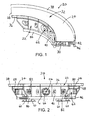
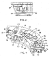
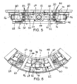
- a bi-directional vibratory feeder constructed in accordance with the teachings of the disclosure is generally referred to by reference numeral 20.
- the feeder 20 may be employed in a variety of different settings including, but not limited to, foundries, agricultural and/or food processing plants, bulk handling and processing plants, and the like. In each of the envisioned settings, the feeder 20 is employed to transport objects along a curved path in either direction, as desired. Furthermore, the rate at which objects are transported is substantially consistent across the entire width of the curved flow path. While the exemplary embodiment of the bi-directional vibratory feeder 20 is described herein as a feeder, that term is employed generically to include both feeders and conveyors.
- the bi-directional vibratory feeder 20 includes a trough assembly 22 having an elongated; generally horizontal bed 24 for supporting objects to be transported.
- the bed 24 defines a curved path 26 extending between first and second ends 28, 30 of the bed 24.
- a loading area generally designated 32 may be provided intermediate the first and second bed ends 28, 30 for receiving objects to be transported.
- the loading area 32 is located generally equidistant from the first and second bed ends 28, 30, however the loading area 32 may be located in other positions.
- the curved path 26 may be shaped as an arc formed about a center point 34. In the illustrated embodiment, the curved path 26 traces a radius distance "r" from the center point 34 and spans a 90° arc about the center point 34.
- multiple columns of smaller objects may be transported wherein the feed rate of the objects is substantially constant across the entire width of the curved flow path (i.e., objects located along the outer rail 38 are advanced more quickly than objects located along the inner rail 36, so that an overall feed rate is substantially constant).
Landscapes
- Engineering & Computer Science (AREA)
- Mechanical Engineering (AREA)
- Jigging Conveyors (AREA)
- Feeding Of Articles To Conveyors (AREA)
Claims (13)
- Ein bidirektionaler Vibrationsförderer (20) zum Transportieren von Objekten auf einem gekrümmten Pfad (26), wobei der Förderer (20) umfasst:eine Wannenanordnung (22), welche ein längliches im Wesentlichen horizontales Bett (24) umfasst, welches den gekrümmten Pfad (26) definiert, wobei die Wannenanordnung (22) einen Schwerpunkt aufweist;biegsame Isolatoren (60), welche mit der Wannenanordnung (22) verbunden sind und so ausgestaltet sind, dass sie die Wannenanordnung (22) gegenüber dem darunterliegenden Terrain isolieren;eine Exzentermassenanordnung (62), welche einen Exzenterrahmen (64) umfasst und einen Vibrationsgenerator (66), welcher gekoppelt ist mit dem Exzenterrahmen (64) zur Erzeugung von Vibrationskräften, wobei die Exzentermassenanordnung (62) einen Schwerpunkt aufweist;zumindest eine horizontal angeordnete biegsame Kupplung, welche zwischen der Exzentermassenanordnung (62) und der Wannenanordnung (22) verbunden ist; undzumindest ein vertikal angeordnetes Gelenk (80), welches zwischen der Exzentermassenanordnung (62) und der Wannenanordnung (22) verbunden ist;wobei die Vibrationskräfte, die durch den Vibrationsgenerator (66) erzeugt werden eine vertikale Komponente umfassen, welche entlang eines im Wesentlichen vertikalen Pfads gerichtet ist, welcher durch einen kombinierten Schwerpunkt der Wannenanordnung (22) und der Exzentermassenanordnung (62) verläuft, welche übertragen wird durch das zumindest eine vertikal angeordnete Gelenk (80), um zu bewirken, dass jeder Punkt auf der Wannenanordnung sich vertikal nach oben bewegt, und eine horizontale Komponente, welche durch zumindest eine horizontal angeordnete biegsame Kupplung übertragen wird, entlang eines Pfades welcher beabstandet ist von dem kombinierten Schwerpunkt, um zu bewirken, das jeder Punkt auf der Wannenanordnung (22) sich entlang eines Pfads bewegt, welcher auf einem Bogen eines Kreises in einer horizontalen Ebene liegt;
wobei der Vibrationsgenerator (66) bedienbar ist in zumindest ersten und zweiten Moden, wobei in dem ersten Modus die horizontale Komponente der Vibrationskräfte entlang eines ersten linearen Pfads gerichtet ist, welcher beabstandet ist von dem kombinierten Schwerpunkt, um das Objekt in einer ersten Richtung entlang des gekrümmten Pfads zu bewegen, und in dem zweiten Modus, wird die horizontale Komponente der Vibrationskraft entlang eines zweiten linearen Pfads geleitet, welcher beabstandet ist von dem kombinierten Schwerpunkt, um die Objekte in einer zweiten, im Wesentlichen entgegen gesetzten Richtung entlang des gekrümmten Pfads zu bewegen. - Der Förderer (20) gemäß Anspruch 1, wobei jeder der Bögen der Pfade entlang derer jeder Punkt auf der Wannenanordnung (22) gedreht wird einen Drehpunkt aufweist.
- Der Förderer (20) gemäß Anspruch 2, wobei eine Position des Drehpunkts im Wesentlichen konstant ist in den ersten und zweiten Moden.
- Der Förderer (20) gemäß Anspruch 2, wobei der gekrümmte Pfad (26) einen Bogen mit einem Mittelpunkt definiert, und wobei der Drehpunkt im Wesentlichen übereinstimmt mit dem Mittelpunkt des gekrümmten Pfads (26).
- Der Förderer (20) gemäß Anspruch 1, wobei der Schwerpunkt der Exzentermassenanordnung (62) und der Schwerpunkt der Wannenanordnung (22) im Wesentlichen übereinstimmen.
- Der Förderer (20) gemäß Anspruch 1, wobei der Vibrationsgenerator (66) einen reversiblen Motor aufweist, welcher einen drehbaren Ausgangsschaft (76) aufweist, welcher zumindest einen Exzenter (78) trägt.
- Der Förderer (20) gemäß Anspruch 6, wobei der reversible Motor in einer ersten Richtung in dem ersten Modus gedreht wird und wobei der reversible Motor in dem zweiten Modus in einer zweiten Richtung gedreht wird welche der ersten Richtung entgegengesetzt ist.
- Der Förderer (20) gemäß Anspruch 6, wobei der zumindest eine Exzenter (78) einen ersten Exzenter aufweist welcher auf einem ersten Ende des Ausgangsschafts (76) angeordnet ist und einen zweiten Exzenter welcher auf einem zweiten entgegengesetzten Ende des Ausgangsschaft angeordnet ist.
- Der Förderer (20) gemäß Anspruch 8, wobei die ersten und zweiten Exzenter (78) unterschiedliche Gewichte aufweisen.
- Der Förderer (20) gemäß Anspruch 1, wobei die zumindest eine biegsame Kupplung zumindest zwei horizontal ausgerichtete Federn (82) aufweist, welche auf entgegengesetzten Seiten des Vibrationsgenerators (66) angeordnet sind.
- Der Förderer (20) gemäß Anspruch 10, wobei die horizontal ausgerichteten Federn (82) Achsen definieren entlang derer die horizontale Komponente der Vibrationskräfte aufgebracht wird, wobei die Achsen nicht den kombinierten Schwerpunkt der Wannenanordnung (22) und der Exzentermassenanordnung (62) schneiden.
- Der Förderer (20) gemäß Anspruch 1, wobei das zumindest ein Gelenk (80) einen vertikal angeordneten Stab (slat) (80) aufweist.
- Der Förderer (20) gemäß Anspruch 1, wobei der gekrümmte Pfad (26) einen Bogen definiert, mit einem Mittelpunkt und wobei der gekrümmte Pfad (26) einen Bogen von 90° aufspannt.
Applications Claiming Priority (2)
| Application Number | Priority Date | Filing Date | Title |
|---|---|---|---|
| US460702 | 2003-06-12 | ||
| US10/460,702 US6827201B1 (en) | 2003-06-12 | 2003-06-12 | Vibratory feeder for transporting objects in a curved path |
Publications (2)
| Publication Number | Publication Date |
|---|---|
| EP1486437A1 EP1486437A1 (de) | 2004-12-15 |
| EP1486437B1 true EP1486437B1 (de) | 2008-05-21 |
Family
ID=33299722
Family Applications (1)
| Application Number | Title | Priority Date | Filing Date |
|---|---|---|---|
| EP04013774A Expired - Lifetime EP1486437B1 (de) | 2003-06-12 | 2004-06-11 | Schwingförderer zum Transport von Gegenständen entlang einer Kurvenbahn |
Country Status (8)
| Country | Link |
|---|---|
| US (1) | US6827201B1 (de) |
| EP (1) | EP1486437B1 (de) |
| JP (1) | JP2005041692A (de) |
| AT (1) | ATE396129T1 (de) |
| AU (1) | AU2004202528B2 (de) |
| BR (1) | BRPI0401953B1 (de) |
| CA (1) | CA2470398C (de) |
| DE (1) | DE602004013881D1 (de) |
Cited By (1)
| Publication number | Priority date | Publication date | Assignee | Title |
|---|---|---|---|---|
| CN106687396A (zh) * | 2014-09-19 | 2017-05-17 | 株式会社石田 | 具备输送槽装卸机构的振动输送装置以及组合计量装置 |
Families Citing this family (10)
| Publication number | Priority date | Publication date | Assignee | Title |
|---|---|---|---|---|
| US6948611B2 (en) * | 1999-07-30 | 2005-09-27 | Kinergy Corporation | Vibratory conveying apparatus adapted to be driven by accumulatively phased rotating eccentric weights |
| CA2511033A1 (en) * | 2002-12-23 | 2004-07-15 | General Kinematics Corporation | Vibratory spiral conveyor |
| US7487868B2 (en) * | 2003-12-23 | 2009-02-10 | General Kinematics Corporation | Vibratory conveyor deck with adjustable curvature |
| US7296951B2 (en) * | 2004-08-25 | 2007-11-20 | General Kinematics Corporation | Vibratory spiral conveyor |
| US7819238B2 (en) * | 2005-10-12 | 2010-10-26 | Delaware Capital Formation, Inc. | Heavy duty slide |
| US20070125624A1 (en) * | 2005-12-06 | 2007-06-07 | General Kinematics Corporation | Vibratory conveyor |
| KR101136047B1 (ko) * | 2010-11-29 | 2012-04-18 | 성안이엔티주식회사 | 토사와 골재에 혼재된 이물질 분리 선별장치 |
| US8517168B2 (en) * | 2011-06-20 | 2013-08-27 | Key Technology, Inc. | Spring for a vibratory conveyor |
| US9950870B2 (en) | 2012-01-20 | 2018-04-24 | Mayfran International | Vertical spiral conveyor |
| US9452890B2 (en) * | 2014-10-17 | 2016-09-27 | Smalley Manufacturing Co., Inc. | Linear wave motion conveyor |
Family Cites Families (19)
| Publication number | Priority date | Publication date | Assignee | Title |
|---|---|---|---|---|
| US3712459A (en) * | 1971-02-12 | 1973-01-23 | Gen Kinematics Corp | Vibratory conveyor |
| US3789977A (en) * | 1972-01-14 | 1974-02-05 | Gen Kinematics Corp | Vibratory vertical lift conveyor |
| US4181216A (en) * | 1977-11-25 | 1980-01-01 | George Cipu | Reversible vibrator, bowl feeder with angled spring supports |
| US4267919A (en) * | 1979-05-21 | 1981-05-19 | Rexnord Inc. | Vibrating spiral conveyor drive |
| US4611709A (en) * | 1979-07-02 | 1986-09-16 | General Kinematics | Vibratory conveyor |
| JPS61114914A (ja) * | 1984-11-07 | 1986-06-02 | Shinko Electric Co Ltd | 振動コンベヤ |
| US4709507A (en) * | 1985-09-19 | 1987-12-01 | General Kinematics Corporation | Tumbling apparatus |
| JPH052492Y2 (de) * | 1987-04-28 | 1993-01-21 | ||
| US5024320A (en) * | 1987-05-08 | 1991-06-18 | General Kinematics Corporation | Vibratory spiral elevator |
| US4844236A (en) * | 1987-07-13 | 1989-07-04 | General Kinematics Corporation | Inclined vibratory conveyor |
| US5054606A (en) * | 1988-05-11 | 1991-10-08 | General Kinematics Corporation | Control system for vibratory apparatus |
| US4926601A (en) * | 1989-03-09 | 1990-05-22 | General Kinematics Corporation | Vibratory tumbling apparatus |
| US5178259A (en) * | 1991-04-30 | 1993-01-12 | General Kinematics | Vibratory conveying apparatus |
| DE9315295U1 (de) * | 1992-11-04 | 1994-01-05 | Jöst GmbH + Co KG, 48249 Dülmen | Mittels Schwingantrieb angetriebener Förderer |
| US5713457A (en) * | 1995-12-06 | 1998-02-03 | General Kinematics Corporation | Two-way vibratory feeder or conveyor |
| US5934446A (en) * | 1997-06-05 | 1999-08-10 | General Kinematics Corporation | Bi-directional vibratory conveyor |
| US6029796A (en) * | 1997-08-26 | 2000-02-29 | General Kinematics Corporation | Two way vibratory conveyor |
| US6112883A (en) * | 1998-08-04 | 2000-09-05 | General Kinematics Corporation | Vibratory distribution conveyor |
| US6155404A (en) * | 1999-06-18 | 2000-12-05 | General Kinematics Corporation | Vibratory conveyors |
-
2003
- 2003-06-12 US US10/460,702 patent/US6827201B1/en not_active Expired - Lifetime
-
2004
- 2004-06-07 CA CA002470398A patent/CA2470398C/en not_active Expired - Lifetime
- 2004-06-09 AU AU2004202528A patent/AU2004202528B2/en not_active Expired
- 2004-06-10 JP JP2004172268A patent/JP2005041692A/ja active Pending
- 2004-06-11 EP EP04013774A patent/EP1486437B1/de not_active Expired - Lifetime
- 2004-06-11 AT AT04013774T patent/ATE396129T1/de not_active IP Right Cessation
- 2004-06-11 BR BRPI0401953A patent/BRPI0401953B1/pt active IP Right Grant
- 2004-06-11 DE DE602004013881T patent/DE602004013881D1/de not_active Expired - Lifetime
Cited By (1)
| Publication number | Priority date | Publication date | Assignee | Title |
|---|---|---|---|---|
| CN106687396A (zh) * | 2014-09-19 | 2017-05-17 | 株式会社石田 | 具备输送槽装卸机构的振动输送装置以及组合计量装置 |
Also Published As
| Publication number | Publication date |
|---|---|
| US20040251114A1 (en) | 2004-12-16 |
| AU2004202528A1 (en) | 2005-01-06 |
| CA2470398C (en) | 2010-03-09 |
| EP1486437A1 (de) | 2004-12-15 |
| CA2470398A1 (en) | 2004-12-12 |
| BRPI0401953B1 (pt) | 2015-12-08 |
| ATE396129T1 (de) | 2008-06-15 |
| BRPI0401953A (pt) | 2005-05-24 |
| US6827201B1 (en) | 2004-12-07 |
| JP2005041692A (ja) | 2005-02-17 |
| AU2004202528B2 (en) | 2009-10-01 |
| DE602004013881D1 (de) | 2008-07-03 |
Similar Documents
| Publication | Publication Date | Title |
|---|---|---|
| US4313535A (en) | Excited frame, vibratory conveying apparatus for moving particulate material | |
| EP1486437B1 (de) | Schwingförderer zum Transport von Gegenständen entlang einer Kurvenbahn | |
| US6029796A (en) | Two way vibratory conveyor | |
| US2951581A (en) | Vibratory conveyors | |
| US4356911A (en) | Linear drive unit for vibratory conveyor | |
| US6705459B1 (en) | Two-way vibratory feeder | |
| US6702102B2 (en) | Exciter mass assembly for a vibratory device | |
| US20050258017A1 (en) | Balanced flat stroke bi-directional conveyor | |
| AU2002352769A1 (en) | Exciter mass assembly for a vibratory device | |
| TW201242869A (en) | Parts feeder | |
| US3746149A (en) | Reversible vibratory feeder | |
| CA2468075A1 (en) | Sifting device | |
| US6041915A (en) | Vibratory conveyor with side-mounted drivers | |
| EP1634825B1 (de) | Linearantrieb für ein Vibrationsgerät | |
| US6298978B1 (en) | Reversing natural frequency vibratory conveyor system | |
| US9266683B1 (en) | Single motor two mass bi-directional conveyor | |
| US3605996A (en) | Material handling apparatus and means to impart vibratory forces thereto | |
| US3212629A (en) | Vibratory conveyor, particularly bin-discharge conveyor | |
| US3056488A (en) | Elastic strut conveyor mount | |
| US4462522A (en) | Vibratory conveyor | |
| CN214288789U (zh) | 干式磁选机 | |
| US10683175B1 (en) | Bi-directional vibratory conveyor apparatuses and methods of using the same | |
| EP1795466A1 (de) | Vibrationsförderer | |
| JP4963335B2 (ja) | 振動フィーダ | |
| GB2151000A (en) | Vibratory conveyor |
Legal Events
| Date | Code | Title | Description |
|---|---|---|---|
| PUAI | Public reference made under article 153(3) epc to a published international application that has entered the european phase |
Free format text: ORIGINAL CODE: 0009012 |
|
| AK | Designated contracting states |
Kind code of ref document: A1 Designated state(s): AT BE BG CH CY CZ DE DK EE ES FI FR GB GR HU IE IT LI LU MC NL PL PT RO SE SI SK TR |
|
| AX | Request for extension of the european patent |
Extension state: AL HR LT LV MK |
|
| 17P | Request for examination filed |
Effective date: 20050615 |
|
| AKX | Designation fees paid |
Designated state(s): AT BE BG CH CY CZ DE DK EE ES FI FR GB GR HU IE IT LI LU MC NL PL PT RO SE SI SK TR |
|
| 17Q | First examination report despatched |
Effective date: 20060711 |
|
| GRAP | Despatch of communication of intention to grant a patent |
Free format text: ORIGINAL CODE: EPIDOSNIGR1 |
|
| GRAS | Grant fee paid |
Free format text: ORIGINAL CODE: EPIDOSNIGR3 |
|
| GRAA | (expected) grant |
Free format text: ORIGINAL CODE: 0009210 |
|
| AK | Designated contracting states |
Kind code of ref document: B1 Designated state(s): AT BE BG CH CY CZ DE DK EE ES FI FR GB GR HU IE IT LI LU MC NL PL PT RO SE SI SK TR |
|
| REG | Reference to a national code |
Ref country code: GB Ref legal event code: FG4D |
|
| RIN1 | Information on inventor provided before grant (corrected) |
Inventor name: DICKINSON, ERIC Inventor name: CHRISTOPHERSON, KURT Inventor name: MARKOWSKI, ROBERT Inventor name: KRAUS, RICHARD B. |
|
| REG | Reference to a national code |
Ref country code: CH Ref legal event code: EP |
|
| REF | Corresponds to: |
Ref document number: 602004013881 Country of ref document: DE Date of ref document: 20080703 Kind code of ref document: P |
|
| REG | Reference to a national code |
Ref country code: CH Ref legal event code: NV Representative=s name: HEPP, WENGER & RYFFEL AG |
|
| REG | Reference to a national code |
Ref country code: IE Ref legal event code: FG4D |
|
| PG25 | Lapsed in a contracting state [announced via postgrant information from national office to epo] |
Ref country code: SI Free format text: LAPSE BECAUSE OF FAILURE TO SUBMIT A TRANSLATION OF THE DESCRIPTION OR TO PAY THE FEE WITHIN THE PRESCRIBED TIME-LIMIT Effective date: 20080521 |
|
| PG25 | Lapsed in a contracting state [announced via postgrant information from national office to epo] |
Ref country code: ES Free format text: LAPSE BECAUSE OF FAILURE TO SUBMIT A TRANSLATION OF THE DESCRIPTION OR TO PAY THE FEE WITHIN THE PRESCRIBED TIME-LIMIT Effective date: 20080901 Ref country code: FI Free format text: LAPSE BECAUSE OF FAILURE TO SUBMIT A TRANSLATION OF THE DESCRIPTION OR TO PAY THE FEE WITHIN THE PRESCRIBED TIME-LIMIT Effective date: 20080521 |
|
| NLV1 | Nl: lapsed or annulled due to failure to fulfill the requirements of art. 29p and 29m of the patents act | ||
| PG25 | Lapsed in a contracting state [announced via postgrant information from national office to epo] |
Ref country code: PL Free format text: LAPSE BECAUSE OF FAILURE TO SUBMIT A TRANSLATION OF THE DESCRIPTION OR TO PAY THE FEE WITHIN THE PRESCRIBED TIME-LIMIT Effective date: 20080521 Ref country code: NL Free format text: LAPSE BECAUSE OF FAILURE TO SUBMIT A TRANSLATION OF THE DESCRIPTION OR TO PAY THE FEE WITHIN THE PRESCRIBED TIME-LIMIT Effective date: 20080521 Ref country code: AT Free format text: LAPSE BECAUSE OF FAILURE TO SUBMIT A TRANSLATION OF THE DESCRIPTION OR TO PAY THE FEE WITHIN THE PRESCRIBED TIME-LIMIT Effective date: 20080521 |
|
| PG25 | Lapsed in a contracting state [announced via postgrant information from national office to epo] |
Ref country code: PT Free format text: LAPSE BECAUSE OF FAILURE TO SUBMIT A TRANSLATION OF THE DESCRIPTION OR TO PAY THE FEE WITHIN THE PRESCRIBED TIME-LIMIT Effective date: 20081021 Ref country code: DK Free format text: LAPSE BECAUSE OF FAILURE TO SUBMIT A TRANSLATION OF THE DESCRIPTION OR TO PAY THE FEE WITHIN THE PRESCRIBED TIME-LIMIT Effective date: 20080521 Ref country code: CZ Free format text: LAPSE BECAUSE OF FAILURE TO SUBMIT A TRANSLATION OF THE DESCRIPTION OR TO PAY THE FEE WITHIN THE PRESCRIBED TIME-LIMIT Effective date: 20080521 Ref country code: MC Free format text: LAPSE BECAUSE OF NON-PAYMENT OF DUE FEES Effective date: 20080630 Ref country code: SE Free format text: LAPSE BECAUSE OF FAILURE TO SUBMIT A TRANSLATION OF THE DESCRIPTION OR TO PAY THE FEE WITHIN THE PRESCRIBED TIME-LIMIT Effective date: 20080821 |
|
| PG25 | Lapsed in a contracting state [announced via postgrant information from national office to epo] |
Ref country code: BE Free format text: LAPSE BECAUSE OF FAILURE TO SUBMIT A TRANSLATION OF THE DESCRIPTION OR TO PAY THE FEE WITHIN THE PRESCRIBED TIME-LIMIT Effective date: 20080521 Ref country code: RO Free format text: LAPSE BECAUSE OF FAILURE TO SUBMIT A TRANSLATION OF THE DESCRIPTION OR TO PAY THE FEE WITHIN THE PRESCRIBED TIME-LIMIT Effective date: 20080521 Ref country code: SK Free format text: LAPSE BECAUSE OF FAILURE TO SUBMIT A TRANSLATION OF THE DESCRIPTION OR TO PAY THE FEE WITHIN THE PRESCRIBED TIME-LIMIT Effective date: 20080521 |
|
| PLBE | No opposition filed within time limit |
Free format text: ORIGINAL CODE: 0009261 |
|
| STAA | Information on the status of an ep patent application or granted ep patent |
Free format text: STATUS: NO OPPOSITION FILED WITHIN TIME LIMIT |
|
| REG | Reference to a national code |
Ref country code: IE Ref legal event code: MM4A |
|
| 26N | No opposition filed |
Effective date: 20090224 |
|
| PG25 | Lapsed in a contracting state [announced via postgrant information from national office to epo] |
Ref country code: BG Free format text: LAPSE BECAUSE OF FAILURE TO SUBMIT A TRANSLATION OF THE DESCRIPTION OR TO PAY THE FEE WITHIN THE PRESCRIBED TIME-LIMIT Effective date: 20080821 Ref country code: EE Free format text: LAPSE BECAUSE OF FAILURE TO SUBMIT A TRANSLATION OF THE DESCRIPTION OR TO PAY THE FEE WITHIN THE PRESCRIBED TIME-LIMIT Effective date: 20080521 Ref country code: IE Free format text: LAPSE BECAUSE OF NON-PAYMENT OF DUE FEES Effective date: 20080611 |
|
| PGFP | Annual fee paid to national office [announced via postgrant information from national office to epo] |
Ref country code: CH Payment date: 20090617 Year of fee payment: 6 |
|
| PG25 | Lapsed in a contracting state [announced via postgrant information from national office to epo] |
Ref country code: HU Free format text: LAPSE BECAUSE OF FAILURE TO SUBMIT A TRANSLATION OF THE DESCRIPTION OR TO PAY THE FEE WITHIN THE PRESCRIBED TIME-LIMIT Effective date: 20081122 Ref country code: CY Free format text: LAPSE BECAUSE OF FAILURE TO SUBMIT A TRANSLATION OF THE DESCRIPTION OR TO PAY THE FEE WITHIN THE PRESCRIBED TIME-LIMIT Effective date: 20080521 Ref country code: LU Free format text: LAPSE BECAUSE OF NON-PAYMENT OF DUE FEES Effective date: 20080611 |
|
| PG25 | Lapsed in a contracting state [announced via postgrant information from national office to epo] |
Ref country code: TR Free format text: LAPSE BECAUSE OF FAILURE TO SUBMIT A TRANSLATION OF THE DESCRIPTION OR TO PAY THE FEE WITHIN THE PRESCRIBED TIME-LIMIT Effective date: 20080521 |
|
| PG25 | Lapsed in a contracting state [announced via postgrant information from national office to epo] |
Ref country code: GR Free format text: LAPSE BECAUSE OF FAILURE TO SUBMIT A TRANSLATION OF THE DESCRIPTION OR TO PAY THE FEE WITHIN THE PRESCRIBED TIME-LIMIT Effective date: 20080822 |
|
| REG | Reference to a national code |
Ref country code: CH Ref legal event code: PL |
|
| PG25 | Lapsed in a contracting state [announced via postgrant information from national office to epo] |
Ref country code: CH Free format text: LAPSE BECAUSE OF NON-PAYMENT OF DUE FEES Effective date: 20100630 Ref country code: LI Free format text: LAPSE BECAUSE OF NON-PAYMENT OF DUE FEES Effective date: 20100630 |
|
| REG | Reference to a national code |
Ref country code: FR Ref legal event code: PLFP Year of fee payment: 13 |
|
| REG | Reference to a national code |
Ref country code: FR Ref legal event code: PLFP Year of fee payment: 14 |
|
| REG | Reference to a national code |
Ref country code: FR Ref legal event code: PLFP Year of fee payment: 15 |
|
| P01 | Opt-out of the competence of the unified patent court (upc) registered |
Effective date: 20230411 |
|
| PGFP | Annual fee paid to national office [announced via postgrant information from national office to epo] |
Ref country code: FR Payment date: 20230622 Year of fee payment: 20 Ref country code: DE Payment date: 20230620 Year of fee payment: 20 |
|
| PGFP | Annual fee paid to national office [announced via postgrant information from national office to epo] |
Ref country code: IT Payment date: 20230623 Year of fee payment: 20 Ref country code: GB Payment date: 20230620 Year of fee payment: 20 |
|
| REG | Reference to a national code |
Ref country code: DE Ref legal event code: R071 Ref document number: 602004013881 Country of ref document: DE |
|
| PG25 | Lapsed in a contracting state [announced via postgrant information from national office to epo] |
Ref country code: GB Free format text: LAPSE BECAUSE OF EXPIRATION OF PROTECTION Effective date: 20240610 |
|
| PG25 | Lapsed in a contracting state [announced via postgrant information from national office to epo] |
Ref country code: GB Free format text: LAPSE BECAUSE OF EXPIRATION OF PROTECTION Effective date: 20240610 |