EP1486379B1 - Vorrichtung zur Stromversorgung zweier Verbraucherpaare - Google Patents
Vorrichtung zur Stromversorgung zweier Verbraucherpaare Download PDFInfo
- Publication number
- EP1486379B1 EP1486379B1 EP04008457A EP04008457A EP1486379B1 EP 1486379 B1 EP1486379 B1 EP 1486379B1 EP 04008457 A EP04008457 A EP 04008457A EP 04008457 A EP04008457 A EP 04008457A EP 1486379 B1 EP1486379 B1 EP 1486379B1
- Authority
- EP
- European Patent Office
- Prior art keywords
- contacts
- contact
- pairs
- pole
- consumer
- Prior art date
- Legal status (The legal status is an assumption and is not a legal conclusion. Google has not performed a legal analysis and makes no representation as to the accuracy of the status listed.)
- Expired - Lifetime
Links
- 239000004020 conductor Substances 0.000 claims description 15
- 238000006073 displacement reaction Methods 0.000 claims description 12
- 239000000615 nonconductor Substances 0.000 claims description 7
- 230000000712 assembly Effects 0.000 abstract 1
- 238000000429 assembly Methods 0.000 abstract 1
- 230000000694 effects Effects 0.000 description 2
- 230000003213 activating effect Effects 0.000 description 1
- 230000004913 activation Effects 0.000 description 1
- 238000010292 electrical insulation Methods 0.000 description 1
- 230000001788 irregular Effects 0.000 description 1
- 239000000463 material Substances 0.000 description 1
- 230000000284 resting effect Effects 0.000 description 1
Images


Classifications
-
- B—PERFORMING OPERATIONS; TRANSPORTING
- B60—VEHICLES IN GENERAL
- B60R—VEHICLES, VEHICLE FITTINGS, OR VEHICLE PARTS, NOT OTHERWISE PROVIDED FOR
- B60R1/00—Optical viewing arrangements; Real-time viewing arrangements for drivers or passengers using optical image capturing systems, e.g. cameras or video systems specially adapted for use in or on vehicles
- B60R1/02—Rear-view mirror arrangements
- B60R1/06—Rear-view mirror arrangements mounted on vehicle exterior
- B60R1/062—Rear-view mirror arrangements mounted on vehicle exterior with remote control for adjusting position
- B60R1/07—Rear-view mirror arrangements mounted on vehicle exterior with remote control for adjusting position by electrically powered actuators
Definitions
- the invention relates to a device for powering two pairs of consumers, in particular two servomotor pairs according to the preamble of claim 1.
- the document shows in detail EP 0 400 633 a remote control switch for adjusting the position of mirrors on a motor vehicle, wherein an actuator is provided in the manner of a joystick having a switch element for closing a plurality of contacts in a corresponding manner in response to a manual operation.
- the plurality of contacts is formed flat, and depending on the movement power supply contacts, which are for example connected to a motor vehicle battery, connected to arranged in the mirrors of the vehicle electric motors for operating the electric motors and for adjusting the mirror position.
- the mechanical arrangement according to the joystick allows rotation of the switch element as well as a shift within the plane of the contact arrangement, to effect in each case the desired adjustment in one or the other direction.
- the arrangement of the contacts on the contact carrier is provided in the form of strips or irregular surface contacts.
- the publication EP 0 481 335 discloses a switching device with a contact arrangement for selectively activating a plurality of consumer devices, wherein a mechanically movable actuator can be adjusted in functionally different positions, so that the respective consumer device associated contacts are activated in a corresponding manner.
- the contacts associated with the respective consumer arrangement are connected to central power supply contacts (voltage of a motor vehicle battery).
- the contact arrangement consists of flat arranged on an insulating plate fixed contacts, which are connected to actuators, such as electric motors, the respective consumer arrangements.
- actuators such as electric motors, the respective consumer arrangements.
- different contacts can be electrically closed, so that electrical energy is selectively supplied to the actuators or electric motors in a desired manner for adjustment in one direction or the other.
- the actuator is displaceable over the flat contact arrangement, while further movable contacts are constantly connected to the actuator.
- the publication US 4,937,402 discloses a switching device by means of which, for example, the position and arrangement of a mirror of a motor vehicle can be adjusted.
- an actuator that is mechanically movable in response to a manual operation, moved to a flat contact arrangement to selectively connect certain contacts with each other or with a central power supply and to effect in one or the other direction, an adjustment of the vehicle mirror.
- fixed contacts are arranged in a longitudinal direction, wherein the activation is effected by moving a manually adjustable actuating element.
- the present invention is based on the object, a device of the type mentioned in such a way that the assignment of stationary, with the consumers, especially servomotors, connected consumer contacts is guaranteed to moving contacts by a simple operation by means of an operating part.
- the stationary pole contacts and load contacts in a plane, preferably as electrically conductive layers, can be arranged on a printed circuit board.
- two movable contact pairs are arranged on the contact carrier.
- the contact carrier is rotatable and displaceable.
- the contact carrier is linearly displaceable in two mutually perpendicular directions back and forth.
- the two contacts of each movable contact pair are connected to an electrical conductor.
- the contact carrier can be rotated into different rotational angle positions, in particular two rotational angle positions, of which each rotational angular position is assigned to a component to be adjusted, in particular an exterior mirror of a motor vehicle.
- the movable contact pairs are moved in the vicinity of pole contacts connected to the plus and minus poles of the power supply source as well as in the vicinity of the stationary load contacts.
- the movable contact pairs are at opposite the load contacts and pole contacts electrically isolated positions. These positions can also define rest or starting positions.
- the movable contact pairs are electrically contacted with the pole contacts and the load contacts of a particular pair of consumers, in particular electric motor pair.
- the rectilinear movements can be linearly moved starting from the respective resting or starting position, ie after rotating the contact carrier, in two opposite directions and two opposite directions perpendicular thereto.
- the pole contacts and the load contacts are preferably arranged on annular surfaces.
- the respective central region of the annular surfaces on which these stationary contacts lie is formed by an electrical insulator. This may be, for example, the electrically insulated surface of a printed circuit board on which the stationary contacts are arranged. If the movable contacts lie on the central, electrically insulated areas of the respective circular ring surfaces equipped with the stationary contacts, the starting position or rest position or also end position for the component to be adjusted, in particular the exterior mirror to be adjusted, can be defined.
- the respective consumer contacts connected to the loads, in particular electric servomotors, are preferably subdivided into a plurality of contact segments.
- the respective contact segments correspond to specific actuating movement directions for the adjustment of the components, in particular the exterior mirrors or rearview mirrors on the vehicle.
- the pole contacts are preferably designed as continuously occupied with electrical contact material annular surfaces.
- the provided on the contact carrier movable contacts are preferably designed as sliding contacts.
- the contact carrier can be connected to an actuating button or actuating lever or equivalent operating or actuating element. With the actuating or operating element, the corresponding movements (rotation and linear displacement) are transmitted to the contact carrier. The movements (rotation, displacement) of the contact carrier take place more advantageously in one plane.
- the exemplary embodiment is preferably used for the power supply of two servomotor pairs with which exterior mirrors or rearview mirrors are adjusted on a motor vehicle.
- two different mirrors for example, the right and left mirrors of the motor vehicle are adjusted separately.
- pole contacts 1, 2 are arranged in the form of electrically conductive layers.
- the pole contact 1 is connected to a positive pole of an electric power source 23, which is designed as a DC power source, for example as a vehicle battery.
- the second pole contact 2 is connected to the negative pole of the power supply source 23.
- the two pole contacts 1, 2 are annular, wherein the annular surfaces are completely coated with electrically conductive material. The polarity can also be reversed, with the first pole contact 1 connected to the negative pole and the second pole contact 2 to the positive pole.
- Consumer contacts 3, 4, 5 and 6 are arranged around the first pole contact 1.
- the electrically conductive layers of the load contacts 3, 4, 5 and 6 are also located on circular ring surfaces.
- Each consumer contact 3, 4, 5 and 6 is divided into three circular ring segments. These contact segments are designated for the load contacts 3 and 4 with a, b, d and for the load contacts 5, 6 with c, d, e. All respective contact segments a, b, c, d, e are electrically connected or short-circuited, as can be seen from the figures.
- the centers of the load contacts 3, 4, 5 and 6 and the middle of the second pole contact 2 are located on a circle around the center of the pole contact. 1
- a contact carrier 7 is rotatably mounted.
- the contact carrier 7 may be circular. However, it may also have any other suitable shape.
- On the contact carrier 7 are movable Contact pairs 10, 11 and 12, 13 attached.
- the movable contacts 10, 11 of the first contact pair are connected via an electrical conductor 8 and the movable contacts 12, 13 of the second contact pair are connected to each other via an electrical conductor 9.
- the movable contacts 10, 11, 12, 13 are preferably designed as sliding contacts.
- the movable contacts 10, 11, 12 and 13 can be pressed in pairs by means not shown leaf springs, which are supported on the contact carrier 7, in the direction of the fixed pole contacts 1, 2 and the stationary load contacts 3, 4, 5 and 6.
- the electrical conductors 8 and 9 act as a connecting conductor or bridging conductor, which are connected only to the associated contact pair 10, 11 and 12, 13.
- Fig. 1 is the starting position or rest position of the contact carrier 7 fixed contact pairs 10, 11 and 12, 13 shown, from which starting a servomotor pair 17, 18, with which one of the two exterior mirrors is adjusted, can be controlled to produce a specific adjustment movement.
- the movable contacts 12 and 13 are located on the electrical insulators 14 in the middle of the pole contact second and the load contact 3.
- the electrical insulators 14 are preferably formed by the electrical insulation layer on a printed circuit board on which the contact arrangement is provided.
- the movable contact pairs 10, 11 and 12, 13 by linear displacement of the contact carrier 7, for example in a vertical direction in the figure upwards, in the in the Fig. 2 moved position shown.
- the pole contact 1 lying at positive potential is connected via the contact pair 10, 11 and the electrical conductor 8 to the contact segment a of the consumer contact 4.
- the pole contact 2 lying at negative potential is connected to the contact segment b of the load contact 3.
- the servo motors 17, 18 are driven in corresponding actuating directions. In this way, the desired setting of an exterior mirror, which is adjusted by the servomotors 17, 18 and the associated actuators 21, 22, can be adjusted.
- the contact carrier vertically up or down or horizontally to the left or to the right from in the Fig. 3 shown position to be moved.
- the contact pairs 10, 11 and 12, 13 are electrically contacted with corresponding contact segments of the load contacts 5 and 6.
- the servomotor pair 15, 16 is brought into the supply circuit of the supply current source 23.
- corresponding adjusting movements of the two servo motors 15, 16 and the associated actuating gear 19 and 20 are generated in response to the respectively associated with the pole contacts 1 and 2 contact segments. In this way, the other exterior mirror is brought into the desired position.
- a circuit program in a switching level for two servomotor pairs with which, for example, two exterior mirrors of a motor vehicle are adjusted to be implemented.
- the occurring in a plane movements of the contact carrier 7 can be generated in a simple manner by a rigid or articulated associated with him control element, for example in the form of a rotary / Schiebeknopfes, control lever and the like.
- By turning the contact carrier 7, for example in a rotation angle of about 60 ° can be changed between the consumer contacts, which are the servomotor pairs of two exterior mirrors of a vehicle, so that both the left and the right side mirrors of the vehicle are operated with the same actuator can.
- a servomotor can cause positioning movements of the mirror about a vertical axis and the other servomotor positioning movements of the mirror about a horizontal axis.
Landscapes
- Engineering & Computer Science (AREA)
- Multimedia (AREA)
- Mechanical Engineering (AREA)
- Rear-View Mirror Devices That Are Mounted On The Exterior Of The Vehicle (AREA)
- Switches With Compound Operations (AREA)
- Details Of Connecting Devices For Male And Female Coupling (AREA)
- Supply And Distribution Of Alternating Current (AREA)
Description
- Die Erfindung betrifft eine Vorrichtung zur Stromversorgung zweier Verbraucherpaare, insbesondere zweier Stellmotorpaare nach dem Oberbegriff des Patentanspruches 1.
- Es ist beispielsweise aus der Druckschrift
DE 43 04 794 A1 bekannt, mit Hilfe eines Stellmotorpaares und zugeordneten Getrieben einen kardanisch gelagerten Außenspiegel eines Kraftfahrzeugs zu bewegen. Sowohl für den rechten Außenspiegel als auch für den linken Außenspiegel wird ein Stellmotor-Paar verwendet. Vor allem in einem Kraftfahrzeug ist es erforderlich, dass der Fahrzeuginsasse die Außenspiegel, welche als Rückspiegel wirken, mittels eines einfach zu betätigenden Einstellmittels in die gewünschten Winkelpositionen zu bringen, wobei die Stellmotore durch geeignete Kontaktgabe mit der Stromversorgungsquelle für die Spiegelbewegung verbunden werden müssen. Diese Problematik ergibt sich auch bei solchen Bauteilen, für welche durch elektrisch betätigte, beispielsweise als Aktuatoren ausgebildete Verbraucher, Stellbewegungen erzeugt werden. - Im Einzelnen zeigt die Druckschrift
EP 0 400 633 einen Fernbedienungsschalter zur Einstellung der Position von Spiegeln an einem Kraftfahrzeug, wobei in der Art eines Joysticks eine Betätigungseinrichtung vorgesehen ist, die ein Schalterelement aufweist zum Schließen einer Vielzahl von Kontakten in entsprechender Weise in Abhängigkeit von einer manuellen Betätigung. Auf einem isolierenden Träger ist die Vielzahl der Kontakte flächig ausgebildet, und es werden in Abhängigkeit von der Bewegung Stromversorgungskontakte, die beispielsweise mit einer Kraftfahrzeugbatterie verbunden sind, mit in den Spiegeln des Fahrzeugs angeordneten Elektromotoren zum Betreiben der Elektromotoren und zur Verstellung der Spiegelposition verbunden. Die mechanische Anordnung gemäß dem Joystick ermöglicht ein Drehen des Schalterelements sowie ein Verschieben innerhalb der Ebene der Kontaktanordnung, um jeweils in der einen oder anderen Richtung die gewünschte Verstellung zu bewirken. Die Anordnung der Kontakte auf dem Kontaktträger ist in Form von Streifen oder unregelmäßig ausgebildeten Flächenkontakten vorgesehen. - Die Druckschrift
EP 0 481 335 offenbart eine Schaltvorrichtung mit einer Kontaktanordnung zum selektiven Aktivieren mehrerer Verbraucheranordnungen, wobei ein mechanisch bewegliches Betätigungsorgan in funktionsmäßig verschiedene Positionen verstellt werden kann, sodass der jeweiligen Verbraucheranordnung zugeordnete Kontakte in entsprechender Weise aktiviert werden. Hierbei werden die der jeweiligen Verbraucheranordnung zugeordneten Kontakte mit zentralen Stromversorgungskontakten (Spannung einer Kraftfahrzeugbatterie) verbunden. Die Kontaktanordnung besteht aus flächig auf einer isolierenden Platte angeordneten feststehenden Kontakten, die mit Betätigungsgliedern, beispielsweise Elektromotoren, der jeweiligen Verbraucheranordnungen verbunden sind. In Abhängigkeit von der jeweiligen Stellung des mechanisch beweglichen Betätigungsorgan können verschiedene Kontakte elektrisch geschlossen werden, sodass in gewünschter Weise den Betätigungsgliedern oder Elektromotoren gezielt für eine Verstellung in die eine oder andere Richtung elektrische Energie zugeführt wird. Insbesondere ist das Betätigungsorgan über die flächig ausgebildete Kontaktanordnung verschiebbar, während weitere bewegliche Kontakte ständig mit dem Betätigungsorgan verbunden sind. - Die Druckschrift
US 4 937 402 offenbart eine Schalteinrichtung, mittels der beispielsweise die Position und Anordnung eines Spiegels eines Kraftfahrzeugs verstellt werden kann. Hierbei wird ein Betätigungsorgan, das mechanisch in Abhängigkeit von einer manuellen Betätigung beweglich ist, auf einer flächig ausgebildeten Kontaktanordnung verschoben, um gezielt bestimmte Kontakte miteinander oder mit einer zentralen Stromversorgung zu verbinden und in die eine oder andere Richtung eine Verstellung des Kraftfahrzeugspiegels zu bewirken. Hierbei sind insbesondere feststehende Kontakte in einer Längsrichtung angeordnet, wobei die Aktivierung durch Verschieben eines manuell verstellbaren Betätigungselements erfolgt. - Der vorliegenden Erfindung liegt demgegenüber die Aufgabe zugrunde, eine Vorrichtung der eingangs genannten Art derart auszugestalten, dass die Zuordnung ortsfester, mit den Verbrauchern, insbesondere Stellmotoren, verbundener Verbraucherkontakte zu beweglichen Kontakten durch eine einfache Bedienung mittels eines Betätigungsteils gewährleistet ist.
- Erfindungsgemäß wird diese Aufgabe durch eine Vorrichtung zur Stromversorgung zweier Verbraucherpaare mit den im Patentanspruch 1 angegebenen Merkmalen gelöst.
- Bei der Erfindung ist die Anordnung der beweglichen Kontaktpaare am Kontaktträger und der ortsfesten, mit den Verbraucherpaaren, insbesondere elektrischen Stellmotorpaaren, verbundenen Verbraucherkontakte sowie der ortsfesten Anordnung der mit der Stromversorgungsquelle verbundenen Polkontakte derart, dass beim Verstellen auf der Kontaktträger nur eine Drehbewegung und eine Verschiebebewegung, vorzugsweise in zwei zueinander senkrechten Richtungen ausführen muss. Ferner können die ortsfesten Polkontakte und Verbraucherkontakte in einer Ebene, vorzugsweise als elektrisch leitfähige Schichten, auf einer gedruckten Leiterplatte angeordnet werden.
- An dem Kontaktträger sind hierzu zwei bewegliche Kontaktpaare angeordnet. Der Kontaktträger ist drehbar und verschiebbar. Insbesondere ist der Kontaktträger linear in zwei senkrecht zueinander liegenden Richtungen hin und her verschiebbar. Die beiden Kontakte eines jeden beweglichen Kontaktpaares sind mit einem elektrischen Leiter verbunden. Der Kontaktträger kann in verschiedene Drehwinkelpositionen, insbesondere zwei Drehwinkelpositionen, von denen jede Drehwinkelposition einem zu verstellenden Bauteil, insbesondere einem Außenspiegel eines Kraftfahrzeugs zugeordnet ist, gedreht werden. Beim Verstellen des Kontaktträgers von einer Winkelposition in die andere Winkelposition werden die beweglichen Kontaktpaare in die Nähe von mit den Plus- und Minuspolen der Stromversorgungsquelle verbundenen Polkontakten sowie in die Nähe der ortsfesten Verbraucherkontakte bewegt. Nach der jeweiligen Drehbewegung befinden sich die beweglichen Kontaktpaare an gegenüber den Verbraucherkontakten und Polkontakten elektrisch isolierten Positionen. Diese Positionen können auch Ruhe- oder Ausgangspositionen definieren. Durch eine vorzugsweise geradlinige Verschiebebewegung unter Beibehaltung der Drehwinkelstellung des Kontaktträgers werden die beweglichen Kontaktpaare mit den Polkontakten und den Verbraucherkontakten eines bestimmten Verbraucherpaares, insbesondere Elektromotor-Paares elektrisch kontaktiert. Die geradlinigen Bewegungen können ausgehend von der jeweiligen Ruhe- oder Ausgangsposition, d. h. nach dem Drehen des Kontaktträgers, in zwei entgegengesetzten Richtungen und zwei dazu senkrecht liegenden entgegengesetzten Richtungen linear bewegt werden.
- Die Polkontakte und die Verbraucherkontakte sind vorzugsweise auf Kreisringflächen angeordnet. Der jeweilige mittlere Bereich der Kreisringflächen, auf denen diese ortsfesten Kontakte liegen, wird von einem elektrischen Isolator gebildet. Es kann sich hier beispielsweise um die elektrisch isolierte Oberfläche einer gedruckten Leiterplatte, auf welcher die ortsfesten Kontakte angeordnet sind, handeln. Wenn die beweglichen Kontakte auf den mittleren, elektrisch isolierten Bereichen der jeweiligen, mit den ortsfesten Kontakten bestückten Kreisringflächen liegen, kann die Ausgangsposition oder Ruheposition oder auch Endposition für das zu verstellende Bauteil, insbesondere den zu verstellenden Außenspiegel definiert sein.
- Vorzugsweise sind die jeweiligen, mit den Verbrauchern, insbesondere elektrischen Stellmotoren verbundenen Verbraucherkontakte in mehrere Kontaktsegmente unterteilt. Die jeweiligen Kontaktsegmente entsprechen bestimmten Stellbewegungsrichtungen für die Verstellung der Bauteile, insbesondere der Außenspiegel bzw. Rückspiegel am Fahrzeug.
- Die Polkontakte sind vorzugsweise als durchgehend mit elektrischem Kontaktierungsmaterial belegte Kreisringflächen ausgebildet.
- Die am Kontaktträger vorgesehenen beweglichen Kontakte sind vorzugsweise als Schleifkontakte ausgebildet.
- Der Kontaktträger kann mit einem Betätigungsknopf oder Betätigungshebel oder gleichwirkendem Bedien- oder Betätigungselement verbunden sein. Mit dem Betätigungs- oder Bedienelement werden die entsprechenden Bewegungen (Drehung und lineare Verschiebung) auf den Kontaktträger übertragen werden. Die Bewegungen (Drehung, Verschiebung) des Kontaktträgers finden vorteilhafter in einer Ebene statt.
- Anhand der Figuren wird an einem Ausführungsbeispiel die Erfindung noch näher erläutert.
- Es zeigt
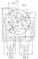
- Fig. 1
- eine schematische Darstellung des Ausführungsbeispiel in einer Ruheposition für einen der beiden Außenspiegel eines Fahrzeugs;
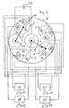
- Fig. 2
- das Ausführungsbeispiel in einer Betriebsstellung zum Verstellen des einen Außenspiegels;
- Fig. 3
- eine Darstellung der Ruheposition, welche dem anderen Außenspiegel zugeordnet ist; und
- Fig. 4
- eine Betriebsstellung beim Verstellen des anderen Außenspiegels.
- Das Ausführungsbeispiel kommt vorzugsweise zur Stromversorgung von zwei Stellmotor-Paaren zur Anwendung, mit denen Außenspiegel bzw. Rückspiegel an einem Kraftfahrzeug verstellt werden. Mit der dargestellten Kontaktanordnung können zwei verschiedene Spiegel, beispielsweise der rechte und linke Außenspiegel des Kraftfahrzeugs separat verstellt werden.
- Auf einer gedruckten Leiterplatte sind ortsfest zwei Polkontakte 1, 2 in Form von elektrisch leitfähigen Schichten angeordnet. Der Polkontakt 1 ist mit einem Pluspol einer elektrischen Stromversorgungsquelle 23, welche als Gleichstromquelle, beispielsweise als Fahrzeugbatterie ausgebildet ist, verbunden. Der zweite Polkontakt 2 ist mit dem Minuspol der Stromversorgungsquelle 23 verbunden. Die beiden Polkontakte 1, 2 sind kreisringförmig ausgebildet, wobei die Kreisringflächen vollständig mit elektrisch leitendem Material beschichtet sind. Die Polung kann auch umgekehrt sein, wobei der erste Polkontakt 1 mit dem Minuspol und der zweite Polkontakt 2 mit dem Pluspol verbunden sind.
- Verbraucherkontakte 3, 4, 5 und 6 sind um den ersten Polkontakt 1 angeordnet. Die elektrisch leitenden Schichten der Verbraucherkontakte 3, 4, 5 und 6 befinden sich ebenfalls auf Kreisringflächen. Jeder Verbraucherkontakt 3, 4, 5 und 6 ist in drei Kreisringsegmente unterteilt. Diese Kontaktsegmente sind für die Verbraucherkontakte 3 und 4 mit a, b, d und für die Verbraucherkontakte 5, 6 mit c, d, e bezeichnet. Alle jeweiligen Kontaktsegmente a, b, c, d, e sind elektrisch miteinander verbunden bzw. kurzgeschlossen, wie aus den Figuren zu ersehen ist. Die Mitten der Verbraucherkontakte 3, 4, 5 und 6 und die Mitte des zweiten Polkontaktes 2 befinden sich auf einem Kreis um den Mittelpunkt des Polkontaktes 1.
- Um diesen Mittelpunkt des Polkontaktes 1 ist ein Kontaktträger 7 drehbar gelagert. Der Kontaktträger 7 kann kreisrund ausgebildet sein. Er kann jedoch auch eine andere beliebige geeignete Form aufweisen. Am Kontaktträger 7 sind bewegliche Kontaktpaare 10, 11 und 12, 13 befestigt. Die beweglichen Kontakte 10, 11 des ersten Kontaktpaares sind über einen elektrischen Leiter 8 und die beweglichen Kontakte 12, 13 des zweiten Kontaktpaares sind über einen elektrischen Leiter 9 miteinander verbunden. Die beweglichen Kontakte 10, 11, 12, 13 sind vorzugsweise als Schleifkontakte ausgebildet. Die beweglichen Kontakte 10, 11, 12 und 13 können paarweise mit Hilfe nicht näher dargestellter Blattfedern, welche am Kontaktträger 7 abgestützt sind, in Richtung auf die ortsfesten Polkontakte 1, 2 und die ortsfesten Verbraucherkontakte 3, 4, 5 und 6 gedrückt werden. Die elektrischen Leiter 8 und 9 wirken als Verbindungsleiter oder Überbrückungsleiter, die nur mit dem zugeordneten Kontaktpaar 10, 11 und 12, 13 verbunden sind.
- In der
Fig. 1 ist die Ausgangsposition oder Ruheposition der am Kontaktträger 7 befestigten Kontaktpaare 10, 11 und 12, 13 dargestellt, von welcher ausgehend ein Stellmotorpaar 17, 18, mit welchem einer der beiden Außenspiegel verstellt wird, zur Erzeugung einer bestimmten Stellbewegung angesteuert werden kann. In der dargestellten Ausgangs- bzw. Ruheposition befinden sich die beweglichen Kontakte 10, 11 an elektrischen Isolatoren 14 in der Mitte des Polkontaktes 1 und des Verbraucherkontaktes 4. Die beweglichen Kontakte 12 und 13 befinden sich auf den elektrischen Isolatoren 14 in den Mitten des Polkontaktes 2 und des Verbraucherkontaktes 3. Die elektrischen Isolatoren 14 werden vorzugsweise von der elektrischen Isolationsschicht auf einer gedruckten Leiterplatte, auf welcher die Kontaktanordnung vorgesehen ist, gebildet. - Aus der in der
Fig. 1 dargestellten Ausgangs- bzw. Ruheposition werden die beweglichen Kontaktpaare 10, 11 und 12, 13 durch lineare Verschiebung des Kontaktträgers 7, beispielsweise in einer vertikalen Richtung in der Figur nach oben, in die in derFig. 2 dargestellten Position verschoben. Hierbei wird der an Pluspotential liegende Polkontakt 1 über das Kontaktpaar 10, 11 und den elektrischen Leiter 8 mit dem Kontaktsegment a des Verbraucherkontaktes 4 verbunden. Ferner wird durch das Kontaktpaar 12, 13 und den elektrischen Leiter 9 der an Minuspotential liegende Polkontakt 2 mit dem Kontaktsegment b des Verbraucherkontaktes 3 verbunden. Durch diese Verschiebung des Kontaktträgers 7 wird der Stellmotor 17 in den Versorgungsstromkreis der Stromversorgungsquelle 23 gelegt. Die vom Stellmotor 17 erzeugte Stellbewegung wird mittels eines zugeordneten Stellgetriebes 21 auf den Spiegel übertragen. Aus denFig. 1 und2 ist ferner zu ersehen, dass durch eine Verschiebung des Kontaktträgers 7 vertikal nach unten durch das Polpaar 10, 11 und den Leiter 8 der Polkontakt 1 mit dem Kontaktsegment b des Verbraucherkontaktes 4 und durch das Kontaktpaar 12, 13 und den Leiter 9 der Polkontakt 2 mit dem Kontaktsegment a des Verbraucherkontaktes 3 verbunden werden. Hierdurch wird ebenfalls der Stellmotor 17 für eine entgegengesetzte Stellbewegungsrichtung an die Stromversorgungsquelle 23 angeschlossen. In gleicher Weise können durch horizontale Bewegungen des Kontaktträgers 7 aus der in derFig. 1 dargestellten Ausgangs- bzw. Ruheposition nach links oder nach rechts in horizontaler Richtung entsprechende Kontaktsegmente der Verbraucherkontakte 4 und 3 mit den Polkontakten 1, 2 verbunden werden, wobei ein Stellmotor 18 mit zugeordneten Stellgetriebe 22 in den Stromkreis der Stromversorgungsquelle 23 geschaltet wird. In Abhängigkeit von den entsprechend kontaktierten Kontaktsegmenten der Verbraucherkontakte 3, 4 werden die Stellmotore 17, 18 in entsprechende Stellrichtungen angesteuert. Hierdurch lässt sich die gewünschte Einstellung des einen Außenspiegels, welcher von den Stellmotoren 17, 18 und den dazugehörigen Stellgetrieben 21, 22 verstellt wird, einstellen. - Beim Verdrehen des Kontaktträgers 7 aus der in der
Fig. 1 dargestellten Position um etwa 60° in die in derFig. 3 dargestellte Position erreicht man die Ausgangs- bzw. Ruheposition der Kontaktpaare 10, 11 und 12, 13, von welcher ausgehend ein Stellmotorpaar 15, 16, mit welchem der andere der beiden Außenspiegel verstellt wird, zur Erzeugung einer bestimmten Stellbewegung angesteuert werden kann. - Zur Erzeugung der entsprechenden Stellbewegung kann, wie bei der Erläuterung der
Fig. 1 und2 der Kontaktträger senkrecht nach oben oder nach unten oder horizontal nach links oder nach rechts aus der in derFig. 3 dargestellten Position bewegt werden. Durch diese linearen Verschiebebewegungen werden die Kontaktpaare 10, 11 und 12, 13 mit entsprechenden Kontaktsegmenten der Verbraucherkontakte 5 und 6 elektrisch kontaktiert. Hierdurch wird das Stellmotorpaar 15, 16 in den Versorgungsstromkreis der Versorgungsstromquelle 23 gebracht. Ferner werden in Abhängigkeit von den jeweils mit den Polkontakten 1 und 2 verbundenen Kontaktsegmenten entsprechende Stellbewegungen der beiden Stellmotore 15, 16 und der zugeordneten Stellgetriebe 19 und 20 erzeugt. Auf diese Weise wird der andere Außenspiegel in die gewünschte Position gebracht. - Bei der in der
Fig. 4 dargestellten Position des Kontaktträgers 7 ist dieser in horizontaler Richtung aus der inFig. 3 dargestellten Position nach rechts bewegt worden. Hierdurch wird der Polkontakt 1 mit dem Kontaktsegment d des Verbraucherkontaktes 6 und der Polkontakt 2 mit dem Kontaktsegment e des Verbraucherkontaktes 5 verbunden. Dabei wird der Stellmotor 16 in den Stromkreis der Versorgungsstromquelle 23 zur Erzeugung einer Stellbewegung in einer bestimmten Richtung geschaltet. Beim horizontalen Verschieben des Kontaktträgers 7 in die andere Richtung werden der Polkontakt 1 mit dem Kontaktsegment e mit dem Kontaktsegment e des Verbraucherkontaktes 6 und der Polkontakt 2 mit dem Kontaktsegment d des Verbraucherkontaktes 5 verbunden. Hierdurch wird ebenfalls der Stellmotor 16 in den Stromkreis der Verbraucherstromquelle mit entgegengesetzter Stellbewegungsrichtung geschaltet. Beispielsweise können hierdurch horizontale Schwenkbewegungen des Spiegels, d.h. Schwenkbewegungen des Spiegels um eine vertikale Achse erzeugt werden. - Beim Verschieben des Kontaktträgers 7 aus der in der
Fig. 3 dargestellten Position in die beiden senkrechten Richtungen wird der Stellmotor 15 mit dem zugeordneten Stellgetriebe 19 zur Erzeugung entsprechender Stellbewegungen in entgegengesetzten Richtungen, beispielsweise zum Verschwenken des Spiegels um eine horizontale Achse geschaltet. - Mit der beschriebenen Kontaktanordnung kann ein Schaltprogramm in einer Schaltebene für zwei Stellmotorpaare, mit denen beispielsweise zwei Außenspiegel eines Kraftfahrzeugs verstellt werden, umgesetzt werden. Die in einer Ebene erfolgenden Bewegungen des Kontaktträgers 7 können in einfacher Weise durch ein starr oder gelenkig mit ihm verbundenes Bedienelement, beispielsweise in Form eines Dreh-/Schiebeknopfes, Bedienhebels und dergleichen erzeugt werden. Durch Drehen des Kontaktträgers 7, z.B. in einem Drehwinkel von etwa 60°, kann zwischen den Verbraucherkontakten, welche den Stellmotorpaaren zweier Außenspiegel eines Fahrzeugs zugeordnet sind, gewechselt werden, so dass mit demselben Betätigungselement sowohl der linke als auch der rechte Außenspiegel des Fahrzeugs bedient werden können. Durch Verschieben des Kontaktträgers bzw. des damit verbundenen Betätigungselementes, vorzugsweise in zwei zueinander senkrechten Richtungen können die entsprechenden Stellmotore in jeweils entgegengesetzten Richtungen Stellbewegungen erzeugen. Dabei kann ein Stellmotor Stellbewegungen des Spiegels um eine vertikale Achse und der andere Stellmotor Stellbewegungen des Spiegels um eine horizontale Achse bewirken.
-
- 1
- Polkontakt (Pluspol)
- 2
- Polkontakt (Minuspol)
- 3
- Verbraucherkontakt
- 4
- Verbraucherkontakt
- 5
- Verbraucherkontakt
- 6
- Verbraucherkontakt
- 7
- Kontaktträger
- 8
- elektrischer Leiter
- 9
- elektrischer Leiter
- 10
- beweglicher Kontakt
- 11
- beweglicher Kontakt
- 12
- beweglicher Kontakt
- 13
- beweglicher Kontakt
- 14
- elektrischer Isolator
- 15, 16
- Stellmotorpaar für ersten Spiegel
- 17, 18
- Stellmotorpaar für zweiten Spiegel
- 19, 20
- Stellgetriebepaar für ersten Spiegel
- 21, 22
- Stellgetriebepaar für zweiten Spiegel
- 23
- Stromversorgungsquelle
Claims (14)
- Vorrichtung zur Stromversorgung zweier Verbraucherpaare, insbesondere elektrischer Stellmotorpaare, mit
mehreren mit den Verbraucherpaaren verbundenen ortsfesten Verbraucherkontakten, welche mit Hilfe beweglicher Kontakte zur wahlweisen Stromversorgung der Verbraucherpaare an Plus- und Minuspolen einer Stromversorgungsquelle anschließbar sind, wobei
zwei bewegliche Kontaktpaare (10, 11 und 12, 13) an einem dreh- und verschiebbaren Kontaktträger (7) angeordnet sind,
die Kontakte jedes beweglichen Kontaktpaares (10, 11 und 12, 13) mit einem elektrischen Leiter (8, 9) verbunden sind,
in einer jeweiligen Drehwinkelposition des Kontaktträgers (7) die einen Kontakte der beiden beweglichen Kontaktpaare (10, 11 und 12, 13) in die Nähe von mit den Plus- und Minuspolen der Stromversorgungsquelle (23) verbundenen Polkontakten (1, 2) und die anderen Kontakte der beiden Kontaktpaare (10, 11 und 12, 13) in die Nähe der ortsfesten Verbraucherkontakte (3, 4 oder 5, 6) eines der beiden Verbraucherpaare bewegbar sind,
die beweglichen Kontaktpaare (10, 11 und 12, 13) durch Verschieben des Kontaktträgers (7) mit den Polkontakten (1, 2) und den Verbraucherkontakten (3, 4 oder 5, 6) des einen Verbraucherpaares elektrisch kontaktiert sind, dadurch gekennzeichnet, dass
die Polkontakte (1, 2) und die Verbräucherkontakte (3, 4, 5, 6) auf Kreisringflächen angeordnet sind, und
die Mitten der Verbraucherkontakte (3, 4, 5, 6) und eines der beiden Polkontakte (1, 2) auf einem Kreisumfang liegen,
und die Mitte des anderen Polkontakts dem Mittelpunkt des Kreisumfangs entspricht. - Vorrichtung nach Anspruch 1, dadurch gekennzeichnet, dass die mittleren Bereiche der Kreisringflächen, in denen die ortsfesten Kontakte (1 bis 6) angeordnet sind, von einem elektrischen Isolator (14) ausgebildet sind.
- Vorrichtung nach einem der Ansprüche 1 bis 2, dadurch gekennzeichnet, dass bei der Anordnung der beweglichen Kontaktpaare (10, 11 und 12, 13) in den mittleren Bereichen der Kreisringflächen, auf denen die ortsfesten Kontakte (1 bis 6) angeordnet sind, eine Ruheposition definiert ist.
- Vorrichtung nach einem der Ansprüche 1 bis 3, dadurch gekennzeichnet, dass der jeweilige Verbraucherkontakt (3, 4, 5, 6) aus mehreren mit dem jeweiligen Verbraucher verbundenen Kontaktsegmenten (a, b, c, d, e) besteht.
- Vorrichtung nach einem der Ansprüche 1 bis 4, dadurch gekennzeichnet, dass die Polkontakte (1, 2) als durchgehend mit einer leitfähigen Schicht versehene Kreisringflächen ausgebildet sind.
- Vorrichtung nach einem der Ansprüche 1 bis 5, dadurch gekennzeichnet, dass in Abhängigkeit von der Verschieberichtung des Kontaktträgers (7) bestimmte Kontaktsegmente (a, b, c, d, e) mit den Polkontakten (1, 2) über die beiden elektrischen Leiter (8, 9) verbunden sind.
- Vorrichtung nach einem der Ansprüche 1 bis 6, dadurch gekennzeichnet, dass die Verbraucherpaare Elektromotorpaare (15, 16 und 17, 18) sind.
- Vorrichtung nach Anspruch 7, dadurch gekennzeichnet, dass jedes Elektromotorpaar (15, 16 und 17, 18) zur Verstellung eines Außenspiegels eines Kraftfahrzeugs ausgebildet ist.
- Vorrichtung nach einem der Ansprüche 1 bis 7, dadurch gekennzeichnet, dass die Kontaktsegmente (a, b, c, d, e) der Verbraucherkontakte (3, 4, 5, 6) bestimmten Verstellbewegungen, welche das jeweilige Elektromotorpaar (15, 16 und 17, 18) erzeugt, zugeordnet sind.
- Vorrichtung nach einem der Ansprüche 1 bis 9, dadurch gekennzeichnet, dass der Kontaktträger (7) um den Mittelpunkt des Pluspotential oder Minuspotential aufweisenden Polkontaktes (1) drehbar ist, wobei bei der Drehung des Kontaktträgers (7) ein beweglicher Kontakt (10) des einen Kontaktpaares (10, 11) auf dem in der Mitte dieses Polkontaktes (1) liegenden elektrischen Isolator (14) aufliegt.
- Vorrichtung nach einem der Ansprüche 1 bis 10, dadurch gekennzeichnet, dass die beweglichen Kontakte (10, 11, 12, 13) als Schleifkontakte ausgebildet sind.
- Vorrichtung nach einem der Ansprüche 1 bis 11, dadurch gekennzeichnet, dass die ortsfesten Kontakte (1 bis 6) in einer Ebene, insbesondere auf einer gedruckten Leiterplatte angeordnet sind.
- Vorrichtung nach einem der Ansprüche 1 bis 12, dadurch gekennzeichnet, dass beim Wechsel zwischen den Verbraucherkontakten (3, 4 und 5, 6) der beiden Verbraucherpaare der Kontaktträger (7) um etwa 60° gedreht wird.
- Vorrichtung nach einem der Ansprüche 1 bis 13, dadurch gekennzeichnet, dass der Kontaktträger in der jeweiligen Drehwinkelposition in zwei zueinander senkrechten Richtungen verschiebbar ist.
Applications Claiming Priority (2)
| Application Number | Priority Date | Filing Date | Title |
|---|---|---|---|
| DE10326277 | 2003-06-11 | ||
| DE10326277A DE10326277B3 (de) | 2003-06-11 | 2003-06-11 | Vorrichtung zur Stromversorgung zweier Verbraucherpaare |
Publications (2)
| Publication Number | Publication Date |
|---|---|
| EP1486379A1 EP1486379A1 (de) | 2004-12-15 |
| EP1486379B1 true EP1486379B1 (de) | 2008-11-05 |
Family
ID=33185741
Family Applications (1)
| Application Number | Title | Priority Date | Filing Date |
|---|---|---|---|
| EP04008457A Expired - Lifetime EP1486379B1 (de) | 2003-06-11 | 2004-04-07 | Vorrichtung zur Stromversorgung zweier Verbraucherpaare |
Country Status (3)
| Country | Link |
|---|---|
| EP (1) | EP1486379B1 (de) |
| AT (1) | ATE413308T1 (de) |
| DE (2) | DE10326277B3 (de) |
Families Citing this family (1)
| Publication number | Priority date | Publication date | Assignee | Title |
|---|---|---|---|---|
| DE102007004673A1 (de) * | 2007-01-25 | 2008-08-07 | Teetronic Gmbh | Mehrfachschalter mit einem dreh- und kippbaren Betätiger für ein verstellbares Kontaktierteil |
Family Cites Families (9)
| Publication number | Priority date | Publication date | Assignee | Title |
|---|---|---|---|---|
| JPS5670936U (de) * | 1979-11-05 | 1981-06-11 | ||
| US4937402A (en) * | 1987-05-29 | 1990-06-26 | Ichikoh Industries Limited | Switching device |
| DE69022118T2 (de) * | 1989-05-30 | 1996-02-15 | Ichiko Industries Ltd | Fernsteuerungsschalter für die Lageeinstellung von Kraftfahrzeugspiegeln. |
| DE4033129A1 (de) * | 1990-10-18 | 1992-04-23 | Hohe Electronics Gmbh & Co Ver | Schaltvorrichtung |
| DE4304794A1 (de) * | 1993-02-17 | 1994-08-18 | Helmut Hartmann | Rückspiegel für ein Kraftfahrzeug |
| US5350891A (en) * | 1993-07-28 | 1994-09-27 | Eaton Corporation | Servomotor remote control switch |
| DE19756052C2 (de) * | 1997-12-17 | 2002-06-27 | Trw Automotive Electron & Comp | Mehrfunktionsschalter |
| JP2003059374A (ja) * | 2001-06-04 | 2003-02-28 | Mic Electron Co | スライドスイッチ |
| DE10218438A1 (de) * | 2002-04-25 | 2003-11-06 | Delphi Tech Inc | Dreh-Schiebeschalter |
-
2003
- 2003-06-11 DE DE10326277A patent/DE10326277B3/de not_active Expired - Fee Related
-
2004
- 2004-04-07 DE DE502004008378T patent/DE502004008378D1/de not_active Expired - Lifetime
- 2004-04-07 AT AT04008457T patent/ATE413308T1/de not_active IP Right Cessation
- 2004-04-07 EP EP04008457A patent/EP1486379B1/de not_active Expired - Lifetime
Also Published As
| Publication number | Publication date |
|---|---|
| DE502004008378D1 (de) | 2008-12-18 |
| EP1486379A1 (de) | 2004-12-15 |
| ATE413308T1 (de) | 2008-11-15 |
| DE10326277B3 (de) | 2004-12-02 |
Similar Documents
| Publication | Publication Date | Title |
|---|---|---|
| EP3427284B1 (de) | Laststufenschalter | |
| EP2147447B1 (de) | Schaltanordnung | |
| EP0447770A2 (de) | Steuervorrichtung zur Handverstellung von reversierbaren elektrischen Verstelleinrichtungen | |
| DE102006007802A1 (de) | Schalterbaugruppe für Fahrzeuge | |
| DE2911103A1 (de) | Vorrichtung zum verschwenken der scheinwerfer von einem kraftfahrzeug | |
| EP0960426A1 (de) | Stellungsmeldeanordnung | |
| DE2751740A1 (de) | Elektroantrieb mit drehwinkelbegrenzung | |
| DE4301961A1 (de) | Verfahren und Vorrichtung zum Betätigen von Einbaukomponenten in Kraftfahrzeugen | |
| DE3249955C2 (de) | Elektrischer Mehrpositions-Schalter | |
| DE3511893C2 (de) | ||
| DE10326277B3 (de) | Vorrichtung zur Stromversorgung zweier Verbraucherpaare | |
| EP3388276A1 (de) | Bedienanordnung zum bedienen von zumindest einem elektrischen gerät mit einem kraftsensor, fahrerassistenzsystem, kraftfahrzeug sowie verfahren zum bedienen einer bedienanordnung | |
| DE69517897T2 (de) | Manuelles Mehrfunktionssteuergerät | |
| DE3636808A1 (de) | Motor-stellvorrichtung | |
| EP4042462B1 (de) | Wähler für laststufenschalter | |
| DE102010002155B4 (de) | Elektrische Maschine mit magnetisch betriebener Kurzschlussvorrichtung | |
| DE228255C (de) | ||
| DE102014114305A1 (de) | Niederstrom-Zündanlassschalter eines Sicherheitssystems eines Fahrzeuges | |
| DE3024848A1 (de) | Schaltungsanordnung zur elektromotorischen verstellung einer einrichtung | |
| DE10141295C2 (de) | Stufenschaltvorrichtung für die Drehzahlstellung eines Elektromotors | |
| DE2812306A1 (de) | Vorrichtung zum verstellen eines kraftfahrzeugsitzes | |
| DE2825179C2 (de) | Kombinierter elektrischer Geräteschalter | |
| DE2548844C2 (de) | Abstimmvorrichtung | |
| DE4030569A1 (de) | Kraftfahrzeug mit auf- und zumachbaren oeffnungen | |
| EP0006569A1 (de) | Stellantrieb für ein in mehrere Ruhelagen einstellbares bewegliches System |
Legal Events
| Date | Code | Title | Description |
|---|---|---|---|
| PUAI | Public reference made under article 153(3) epc to a published international application that has entered the european phase |
Free format text: ORIGINAL CODE: 0009012 |
|
| AK | Designated contracting states |
Kind code of ref document: A1 Designated state(s): AT BE BG CH CY CZ DE DK EE ES FI FR GB GR HU IE IT LI LU MC NL PL PT RO SE SI SK TR |
|
| AX | Request for extension of the european patent |
Extension state: AL HR LT LV MK |
|
| 17P | Request for examination filed |
Effective date: 20050307 |
|
| AKX | Designation fees paid |
Designated state(s): AT BE BG CH CY CZ DE DK EE ES FI FR GB GR HU IE IT LI LU MC NL PL PT RO SE SI SK TR |
|
| 17Q | First examination report despatched |
Effective date: 20071105 |
|
| GRAP | Despatch of communication of intention to grant a patent |
Free format text: ORIGINAL CODE: EPIDOSNIGR1 |
|
| GRAS | Grant fee paid |
Free format text: ORIGINAL CODE: EPIDOSNIGR3 |
|
| GRAA | (expected) grant |
Free format text: ORIGINAL CODE: 0009210 |
|
| AK | Designated contracting states |
Kind code of ref document: B1 Designated state(s): AT BE BG CH CY CZ DE DK EE ES FI FR GB GR HU IE IT LI LU MC NL PL PT RO SE SI SK TR |
|
| REG | Reference to a national code |
Ref country code: GB Ref legal event code: FG4D Free format text: NOT ENGLISH |
|
| REG | Reference to a national code |
Ref country code: CH Ref legal event code: EP |
|
| REG | Reference to a national code |
Ref country code: IE Ref legal event code: FG4D Free format text: LANGUAGE OF EP DOCUMENT: GERMAN |
|
| REF | Corresponds to: |
Ref document number: 502004008378 Country of ref document: DE Date of ref document: 20081218 Kind code of ref document: P |
|
| REG | Reference to a national code |
Ref country code: SE Ref legal event code: TRGR |
|
| NLV1 | Nl: lapsed or annulled due to failure to fulfill the requirements of art. 29p and 29m of the patents act | ||
| PG25 | Lapsed in a contracting state [announced via postgrant information from national office to epo] |
Ref country code: ES Free format text: LAPSE BECAUSE OF FAILURE TO SUBMIT A TRANSLATION OF THE DESCRIPTION OR TO PAY THE FEE WITHIN THE PRESCRIBED TIME-LIMIT Effective date: 20090216 |
|
| PG25 | Lapsed in a contracting state [announced via postgrant information from national office to epo] |
Ref country code: NL Free format text: LAPSE BECAUSE OF FAILURE TO SUBMIT A TRANSLATION OF THE DESCRIPTION OR TO PAY THE FEE WITHIN THE PRESCRIBED TIME-LIMIT Effective date: 20081105 Ref country code: SI Free format text: LAPSE BECAUSE OF FAILURE TO SUBMIT A TRANSLATION OF THE DESCRIPTION OR TO PAY THE FEE WITHIN THE PRESCRIBED TIME-LIMIT Effective date: 20081105 Ref country code: FI Free format text: LAPSE BECAUSE OF FAILURE TO SUBMIT A TRANSLATION OF THE DESCRIPTION OR TO PAY THE FEE WITHIN THE PRESCRIBED TIME-LIMIT Effective date: 20081105 Ref country code: PL Free format text: LAPSE BECAUSE OF FAILURE TO SUBMIT A TRANSLATION OF THE DESCRIPTION OR TO PAY THE FEE WITHIN THE PRESCRIBED TIME-LIMIT Effective date: 20081105 |
|
| REG | Reference to a national code |
Ref country code: IE Ref legal event code: FD4D |
|
| PG25 | Lapsed in a contracting state [announced via postgrant information from national office to epo] |
Ref country code: RO Free format text: LAPSE BECAUSE OF FAILURE TO SUBMIT A TRANSLATION OF THE DESCRIPTION OR TO PAY THE FEE WITHIN THE PRESCRIBED TIME-LIMIT Effective date: 20081105 Ref country code: IE Free format text: LAPSE BECAUSE OF FAILURE TO SUBMIT A TRANSLATION OF THE DESCRIPTION OR TO PAY THE FEE WITHIN THE PRESCRIBED TIME-LIMIT Effective date: 20081105 Ref country code: EE Free format text: LAPSE BECAUSE OF FAILURE TO SUBMIT A TRANSLATION OF THE DESCRIPTION OR TO PAY THE FEE WITHIN THE PRESCRIBED TIME-LIMIT Effective date: 20081105 Ref country code: DK Free format text: LAPSE BECAUSE OF FAILURE TO SUBMIT A TRANSLATION OF THE DESCRIPTION OR TO PAY THE FEE WITHIN THE PRESCRIBED TIME-LIMIT Effective date: 20081105 Ref country code: BG Free format text: LAPSE BECAUSE OF FAILURE TO SUBMIT A TRANSLATION OF THE DESCRIPTION OR TO PAY THE FEE WITHIN THE PRESCRIBED TIME-LIMIT Effective date: 20090205 |
|
| PG25 | Lapsed in a contracting state [announced via postgrant information from national office to epo] |
Ref country code: CZ Free format text: LAPSE BECAUSE OF FAILURE TO SUBMIT A TRANSLATION OF THE DESCRIPTION OR TO PAY THE FEE WITHIN THE PRESCRIBED TIME-LIMIT Effective date: 20081105 Ref country code: PT Free format text: LAPSE BECAUSE OF FAILURE TO SUBMIT A TRANSLATION OF THE DESCRIPTION OR TO PAY THE FEE WITHIN THE PRESCRIBED TIME-LIMIT Effective date: 20090406 |
|
| PLBE | No opposition filed within time limit |
Free format text: ORIGINAL CODE: 0009261 |
|
| STAA | Information on the status of an ep patent application or granted ep patent |
Free format text: STATUS: NO OPPOSITION FILED WITHIN TIME LIMIT |
|
| PG25 | Lapsed in a contracting state [announced via postgrant information from national office to epo] |
Ref country code: SK Free format text: LAPSE BECAUSE OF FAILURE TO SUBMIT A TRANSLATION OF THE DESCRIPTION OR TO PAY THE FEE WITHIN THE PRESCRIBED TIME-LIMIT Effective date: 20081105 |
|
| 26N | No opposition filed |
Effective date: 20090806 |
|
| BERE | Be: lapsed |
Owner name: ROBERT SEUFFER G.M.B.H. & CO. KG Effective date: 20090430 |
|
| REG | Reference to a national code |
Ref country code: CH Ref legal event code: PL |
|
| GBPC | Gb: european patent ceased through non-payment of renewal fee |
Effective date: 20090407 |
|
| PG25 | Lapsed in a contracting state [announced via postgrant information from national office to epo] |
Ref country code: LI Free format text: LAPSE BECAUSE OF NON-PAYMENT OF DUE FEES Effective date: 20090430 Ref country code: CH Free format text: LAPSE BECAUSE OF NON-PAYMENT OF DUE FEES Effective date: 20090430 |
|
| PG25 | Lapsed in a contracting state [announced via postgrant information from national office to epo] |
Ref country code: GB Free format text: LAPSE BECAUSE OF NON-PAYMENT OF DUE FEES Effective date: 20090407 Ref country code: MC Free format text: LAPSE BECAUSE OF NON-PAYMENT OF DUE FEES Effective date: 20090430 |
|
| PG25 | Lapsed in a contracting state [announced via postgrant information from national office to epo] |
Ref country code: BE Free format text: LAPSE BECAUSE OF NON-PAYMENT OF DUE FEES Effective date: 20090430 |
|
| PG25 | Lapsed in a contracting state [announced via postgrant information from national office to epo] |
Ref country code: AT Free format text: LAPSE BECAUSE OF NON-PAYMENT OF DUE FEES Effective date: 20090407 |
|
| PG25 | Lapsed in a contracting state [announced via postgrant information from national office to epo] |
Ref country code: GR Free format text: LAPSE BECAUSE OF FAILURE TO SUBMIT A TRANSLATION OF THE DESCRIPTION OR TO PAY THE FEE WITHIN THE PRESCRIBED TIME-LIMIT Effective date: 20090206 |
|
| PG25 | Lapsed in a contracting state [announced via postgrant information from national office to epo] |
Ref country code: IT Free format text: LAPSE BECAUSE OF FAILURE TO SUBMIT A TRANSLATION OF THE DESCRIPTION OR TO PAY THE FEE WITHIN THE PRESCRIBED TIME-LIMIT Effective date: 20081105 |
|
| PG25 | Lapsed in a contracting state [announced via postgrant information from national office to epo] |
Ref country code: LU Free format text: LAPSE BECAUSE OF NON-PAYMENT OF DUE FEES Effective date: 20090407 |
|
| PG25 | Lapsed in a contracting state [announced via postgrant information from national office to epo] |
Ref country code: HU Free format text: LAPSE BECAUSE OF FAILURE TO SUBMIT A TRANSLATION OF THE DESCRIPTION OR TO PAY THE FEE WITHIN THE PRESCRIBED TIME-LIMIT Effective date: 20090506 |
|
| PG25 | Lapsed in a contracting state [announced via postgrant information from national office to epo] |
Ref country code: TR Free format text: LAPSE BECAUSE OF FAILURE TO SUBMIT A TRANSLATION OF THE DESCRIPTION OR TO PAY THE FEE WITHIN THE PRESCRIBED TIME-LIMIT Effective date: 20081105 |
|
| PG25 | Lapsed in a contracting state [announced via postgrant information from national office to epo] |
Ref country code: CY Free format text: LAPSE BECAUSE OF FAILURE TO SUBMIT A TRANSLATION OF THE DESCRIPTION OR TO PAY THE FEE WITHIN THE PRESCRIBED TIME-LIMIT Effective date: 20081105 |
|
| REG | Reference to a national code |
Ref country code: DE Ref legal event code: R082 Ref document number: 502004008378 Country of ref document: DE Representative=s name: WINTER, BRANDL, FUERNISS, HUEBNER, ROESS, KAIS, DE |
|
| REG | Reference to a national code |
Ref country code: DE Ref legal event code: R082 Ref document number: 502004008378 Country of ref document: DE Representative=s name: WINTER, BRANDL, FUERNISS, HUEBNER, ROESS, KAIS, DE |
|
| PGFP | Annual fee paid to national office [announced via postgrant information from national office to epo] |
Ref country code: SE Payment date: 20140423 Year of fee payment: 11 |
|
| REG | Reference to a national code |
Ref country code: SE Ref legal event code: EUG |
|
| PG25 | Lapsed in a contracting state [announced via postgrant information from national office to epo] |
Ref country code: SE Free format text: LAPSE BECAUSE OF NON-PAYMENT OF DUE FEES Effective date: 20150408 |
|
| REG | Reference to a national code |
Ref country code: FR Ref legal event code: PLFP Year of fee payment: 13 |
|
| REG | Reference to a national code |
Ref country code: FR Ref legal event code: PLFP Year of fee payment: 14 |
|
| REG | Reference to a national code |
Ref country code: FR Ref legal event code: PLFP Year of fee payment: 15 |
|
| PGFP | Annual fee paid to national office [announced via postgrant information from national office to epo] |
Ref country code: DE Payment date: 20180430 Year of fee payment: 15 |
|
| PGFP | Annual fee paid to national office [announced via postgrant information from national office to epo] |
Ref country code: FR Payment date: 20180424 Year of fee payment: 15 |
|
| REG | Reference to a national code |
Ref country code: DE Ref legal event code: R119 Ref document number: 502004008378 Country of ref document: DE |
|
| PG25 | Lapsed in a contracting state [announced via postgrant information from national office to epo] |
Ref country code: DE Free format text: LAPSE BECAUSE OF NON-PAYMENT OF DUE FEES Effective date: 20191101 |
|
| PG25 | Lapsed in a contracting state [announced via postgrant information from national office to epo] |
Ref country code: FR Free format text: LAPSE BECAUSE OF NON-PAYMENT OF DUE FEES Effective date: 20190430 |