EP1486376A1 - Dispositif de commande permettant d'activer et de désactiver des fonctionnalités d'un véhicule - Google Patents
Dispositif de commande permettant d'activer et de désactiver des fonctionnalités d'un véhicule Download PDFInfo
- Publication number
- EP1486376A1 EP1486376A1 EP04360058A EP04360058A EP1486376A1 EP 1486376 A1 EP1486376 A1 EP 1486376A1 EP 04360058 A EP04360058 A EP 04360058A EP 04360058 A EP04360058 A EP 04360058A EP 1486376 A1 EP1486376 A1 EP 1486376A1
- Authority
- EP
- European Patent Office
- Prior art keywords
- control device
- lever
- positioning member
- indexing
- locating surface
- Prior art date
- Legal status (The legal status is an assumption and is not a legal conclusion. Google has not performed a legal analysis and makes no representation as to the accuracy of the status listed.)
- Granted
Links
- 239000002184 metal Substances 0.000 claims description 8
- 229910052751 metal Inorganic materials 0.000 claims description 8
- 230000000295 complement effect Effects 0.000 claims description 5
- 238000006073 displacement reaction Methods 0.000 claims description 5
- 230000006835 compression Effects 0.000 claims description 4
- 238000007906 compression Methods 0.000 claims description 4
- 238000002347 injection Methods 0.000 claims description 4
- 239000007924 injection Substances 0.000 claims description 4
- 238000000465 moulding Methods 0.000 claims description 3
- 230000003213 activating effect Effects 0.000 claims description 2
- 230000009849 deactivation Effects 0.000 description 3
- 230000004913 activation Effects 0.000 description 2
- 230000008859 change Effects 0.000 description 2
- 239000000470 constituent Substances 0.000 description 1
- 230000000694 effects Effects 0.000 description 1
- 230000005032 impulse control Effects 0.000 description 1
- 239000000463 material Substances 0.000 description 1
- 239000000243 solution Substances 0.000 description 1
Images

Classifications
-
- B—PERFORMING OPERATIONS; TRANSPORTING
- B60—VEHICLES IN GENERAL
- B60Q—ARRANGEMENT OF SIGNALLING OR LIGHTING DEVICES, THE MOUNTING OR SUPPORTING THEREOF OR CIRCUITS THEREFOR, FOR VEHICLES IN GENERAL
- B60Q1/00—Arrangement of optical signalling or lighting devices, the mounting or supporting thereof or circuits therefor
- B60Q1/02—Arrangement of optical signalling or lighting devices, the mounting or supporting thereof or circuits therefor the devices being primarily intended to illuminate the way ahead or to illuminate other areas of way or environments
- B60Q1/04—Arrangement of optical signalling or lighting devices, the mounting or supporting thereof or circuits therefor the devices being primarily intended to illuminate the way ahead or to illuminate other areas of way or environments the devices being headlights
- B60Q1/14—Arrangement of optical signalling or lighting devices, the mounting or supporting thereof or circuits therefor the devices being primarily intended to illuminate the way ahead or to illuminate other areas of way or environments the devices being headlights having dimming means
- B60Q1/1446—Arrangement of optical signalling or lighting devices, the mounting or supporting thereof or circuits therefor the devices being primarily intended to illuminate the way ahead or to illuminate other areas of way or environments the devices being headlights having dimming means controlled by mechanically actuated switches
- B60Q1/1453—Hand actuated switches
- B60Q1/1461—Multifunction switches for dimming headlights and controlling additional devices, e.g. for controlling direction indicating lights
- B60Q1/1469—Multifunction switches for dimming headlights and controlling additional devices, e.g. for controlling direction indicating lights controlled by or attached to a single lever, e.g. steering column stalk switches
Definitions
- the present invention relates to a control device to activate and deactivate vehicle functions.
- These devices are for example used to control a windshield wiper, a buzzer or light, an indicator change of direction or any other function of a vehicle it should activate and deactivate at one time or another.
- the invention therefore finds its application also for devices impulse control.
- a control device comprising an actuating member moving by relative to at least one stable position.
- the device includes means drive, including a link arm pivoting on the one hand on the body actuation and secondly on the housing containing said device.
- Another object of the present invention is to reduce the size and the number of moving parts relative to each other and thus reduce the number of assembly steps of the device, as well as the time necessary for these assembly steps.
- the drive means comprise at least one arm pivoting link on the actuating member and at least one film hinge connecting the link to the positioning member.
- film hinge any mechanical connection between two elements, obtained by a flexible zone and / or a shrinking of material.
- the film hinge, the link arm and the switching carriage are thus made in one piece, obtained for example by plastic injection.
- the price cost of the device according to the invention is therefore reduced compared to known solutions.
- the actuator can also move by following translation its longitudinal axis. This allows for example to order functionalities special.
- the actuating member is a lever actuation pivoting around at least one axis I during its movement.
- the axis I preferably extends in a plane extension parallel to the extension plane of the locating surface.
- the pivot axis of the link arm (s) is parallel to the pivot axis I of the actuating lever.
- the device comprises an indexing surface fixed relative to the support, an indexing finger mounted on the actuation lever and movable towards the indexing surface, a compression spring requesting the indexing finger which bears on the indexing surface, which defines using a relief, at least one stable position for the finger indexing lever.
- the indexing surface extends substantially perpendicular to the locating surface.
- the indexing surface defines at least one stable position, called normal, on the path of the indexing finger in a direction substantially orthogonal to the locating surface, and at least one position stable or not, called parallel, on another path of the indexing finger according to a direction substantially parallel to the locating surface, for each position stable known as normal, at least one stable or non-so-called parallel position, being accessible.
- the actuation lever In a stable position, the actuation lever remains in position until a next manipulation, and does not automatically return to its position vertical.
- the actuation lever also has a complementary pivot axis J, orthogonal to the pivot axis I and to the locating surface.
- the link arm or arms are mounted by clipping on a pivot axis secured to the actuating lever.
- the link arm or arms are linked to the lever actuation through at least one additional film hinge.
- the link arm or arms, the positioning and actuation lever are made in one piece, by example by injection or molding.
- the link arm is connected to the lever actuation via a mechanical connection of the ball joint type, authorizing a displacement by translation of the positioning member, during a pivoting of the actuation lever about an axis K perpendicular to the axis I and extending in a plane substantially parallel to the plane of extension of the surface of location.
- the drive means comprising at at least one link arm, the positioning member and at least one film cam constituting a sub-assembly, which is pivotally mounted on the lever actuation via a mechanical connection of the ball joint type, authorizing a pivoting of said lever around three axes (I, J, K), including two (I, K) orthonormal extend in a plane substantially parallel to the plane of extension of the surface and the third (J) of which is orthogonal to the pivot axis (I) and to the locating surface.
- the locating surface is a surface of contact
- the means for determining the position of the positioning member being produced by electrical switching.
- the electrical switches are made with double electrical contacts housed in the positioning device, which constitutes a switching carriage.
- the electrical switches are made with flexible metal blades, integral with the positioning member.
- the electrical switches are made with switching rollers.
- the means for determining the position include capacitive sensors.
- the means for determining the position include position or motion sensors.
- the present invention relates to a control device allowing by example of activating and deactivating features of a vehicle.
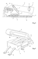
- Such control device is shown for example in Figures 1 to 4.
- the control device according to the invention comprises an actuating member pivoting around an axis I to occupy for example several positions including less one is stable.
- the actuator moves between two stable positions accessible by pivoting about the axis I of said member actuating.
- Each of the stable positions thus corresponds to an activation or deactivation of one or more functionalities.
- the device control also includes a positioning member moving on a marking surface 3.
- the marking surface 3 is for example a surface contact with overmolded conductive grids or printed circuits flexible, or a surface with conductive areas along the path of the positioning member.
- the latter consists for example of a carriage switching 2.
- the locating surface 3 in association with means of determination position, determines the position of the positioning member.
- Each position of the positioning member corresponds to an activation or deactivation of at least one vehicle functionality or a change status of a function.
- the means for determining the position are for example made thanks to electrical switches. These are carried out with double electrical contacts housed in the positioning device, which constitutes the switching carriage 2.
- the means for determining the position include capacitive sensors, known as such or sensors position or movement.
- the control device also comprises means drive connecting the switching carriage 2 to the operating lever 1 and moving said carriage with the pivoting of the actuation lever 1.
- the drive means comprise at least one pivoting link arm 4 around an axis H on the actuating lever 1 and at least one film hinge 5 connecting the link arm 4 to the switching carriage 2.
- the film hinge 5 thus makes it possible to transform a pivoting movement of the actuating lever 1 in one movement or planar displacement of the carriage 2.
- the extension plane in which the carriage moves switching 2 is therefore parallel to the locating surface 3.
- the actuation lever 1 pivots along the axis I, preferably extending in an extension plane parallel to the extension plane of the locating surface 3.
- pivot axis H of the link arm (s) 4 is parallel to the axis pivoting I of the actuating lever 1. This allows, in combination with the film hinge 5, to transform a pivoting movement of the lever actuation 1 in a translational movement of the switching carriage 2.
- the switching carriage 2 has metal blades 6 partially overmolded and making electrical contacts on the locating surface 3.
- the metal blades 6 advantageously have flexibility ensuring reliability electrical contacts on the locating surface 3.
- the link arm 4 exerts a push on the switching carriage 2, making it possible to obtain a displacement of said carriage in an extension plane parallel to the surface of marking 3.
- the metal blades 6 allowing electrical switching can advantageously be replaced by maintained switching rollers in position by springs extending orthogonally to the surface marking 3, which constitutes a contact surface.
- the control device also includes a fixed indexing surface 7 and a finger indexing lever 8 mounted on the actuation lever 1.
- the indexing finger 8 is moves longitudinally with respect to the actuating lever 1 under the effect of a compression spring 9 urging the indexing finger 8.
- the latter comes in support on the indexing surface 7, which defines by means of a relief, at least one or for example two stable positions for the indexing finger 8 and by therefore for the operating lever 1.
- the indexing surface 7 is a part integral with a support 10 on which the locating surface 3 is attached.
- compression spring 9 thus makes it possible to push the indexing finger 8 against the relief of the indexing surface 7 whose configuration makes it possible to define the positions of the actuating lever 1. At each position of the lever actuation 1 corresponds to a positioning of the switching carriage 2 on the marking surface 3.
- the actuation lever 1 has an axis additional pivot point J, perpendicular to the pivot axis I and the marking surface 3. Such pivoting of the actuation lever 1 causes also a pivoting of the switching carriage 2 in a plane parallel to the locating surface 3. The metal blades 6 can thus reach additional electrical contacts.
- the indexing surface 7 defines at least one stable position, called normal, on the path of the indexing finger 8, extending in a direction substantially orthogonal to the marking surface 3.
- the indexing surface 7 also defines at least one stable position, called parallel, on another path of the indexing finger 8, extending in a direction substantially parallel to the locating surface 3. For each so-called stable position normal, at least one stable position called parallel is accessible.
- the indexing surface 7 extends substantially perpendicular to the locating surface 3.
- the indexing surface 7 allows define for example two so-called normal stable positions extending along a direction substantially orthogonal to the locating surface 3 and for example two stable so-called parallel positions extending in one direction substantially parallel to the locating surface 3.
- two so-called parallel stable positions are accessible for each of the so-called normal stable positions.
- Figure 1 shows the control device with the lever actuation 1 in a central position corresponding for example to a deactivation of all accessible features.
- Figures 2 and 3 correspond respectively to a first and a second switching position for the switching carriage 2.
- lever actuation 1 pivots around axis J.
- FIG. 4 representing an exemplary embodiment of the switching carriage 2 shows on the one hand the metal blades 6 partially overmolded in the structure of the switching carriage 2 and on the other hand, the link arm 4 connected to the switching carriage 2 via the film hinge 5. The latter creates an elastic connection zone between the connection arm 4 and the carriage switching 2.
- the link arm 4 also has at its upper end a substantially cylindrical passage 4b allowing it to be mounted for example by clipping on the pivot axis H secured to the actuating lever 1.
- the switching carriage 2 is provided laterally with projecting edges longitudinal 2a intended to engage in corresponding grooves integral with the locating surface 3, the support 10 or the structural element comprising axes I and J. This gives relative guidance and positioning optimal between the switching carriage 2 and the marking surface 3 along of its sliding on said locating surface 3.
- a pivoting around the axis J of the actuating lever 1 is however impossible except in the case where the grooves receiving the projecting edges 2a can pivot around the axis J and are not attached to the locating surface 3.
- the carriage switching 2 can be provided with two link arms 4 located on either side and on the other side of the actuation lever 1.
- the actuation lever 1 can be pivoted at turn of the K axis perpendicular to the axes I and J.
- the carriage 2 then moves by translation in direction I on the locating surface 3.
- the link between the link arm 4 and the actuation lever 1 is a link elastic ball joint.
- the drive means comprise at least one arm delivery 4, the positioning member and at least one film hinge 5, constituting thus a subset.
- the latter is pivotally mounted on the actuation lever 1 via a mechanical connection of the ball joint type, allowing a pivoting of said lever 1 around three axes I, J, K.
- the axes I and K are orthonormal and extend in a plane substantially parallel to the plane of extension of the marking surface 3.
- the third axis J is orthogonal to the pivot axis I and to the locating surface 3.
- the link arm (s) 4, the carriage 2 and the actuating lever 1 are made in one piece, for example by injection or molding.
- the link arm (s) 4 are then linked to the actuation lever 1 through at least one additional film hinge.
- the axis I is fixed relative to the support and to the locating surface 3.
- the J axis shown for example in Figure 3, is then dissociated from the subset comprising the axis I, the locating surface 3 and the support 10. It is in fact the sub-assembly mentioned above I, 3, 10 which pivots around the axis J. This pivoting is then controlled by an additional indexing surface and indexing finger, not represented.
- a subset is thus obtained independent of a housing or a frame in which the conforming device is mounted to the invention.
- the structural and functional simplification of the constituent parts said device also contributes to operational reliability as well as optimized footprint.
Landscapes
- Engineering & Computer Science (AREA)
- Mechanical Engineering (AREA)
- Mechanical Control Devices (AREA)
Abstract
- un organe d'actionnement se déplaçant par rapport à au moins une position stable,
- un organe de positionnement se déplaçant sur une surface de repérage (3) rapportée sur un support (10),
- des moyens d'entraínement reliant l'organe de positionnement à l'organe d'actionnement et déplaçant l'organe de positionnement avec une manipulation de l'organe d'actionnement,
- des moyens de détermination de la position ou du mouvement de l'organe de positionnement sur la surface de repérage (3),
les moyens d'entraínement comportent au moins un bras de liaison (4), pivotant sur l'organe d'actionnement, et au moins une charnière film (5) reliant le bras de liaison (4) à l'organe de positionnement.
Description
- un organe d'actionnement se déplaçant par rapport à au moins une position stable,
- un organe de positionnement se déplaçant sur une surface de
repérage rapportée sur un support,
des moyens d'entraínement reliant l'organe de positionnement à l'organe d'actionnement et déplaçant l'organe de positionnement avec une manipulation de l'organe d'actionnement, - des moyens de détermination de la position ou du mouvement de l'organe de positionnement sur la surface de repérage.
- la figure 1 est une vue en coupe longitudinale d'un exemple de réalisation d'un dispositif de commande conforme à l'invention,
- les figures 2 et 3 correspondent à des positionnements différents d'un levier d'actionnement du dispositif de commande de la figure 1,
- la figure 4 représente une vue en perspective d'un exemple de réalisation d'un chariot de commutation d'un dispositif de commande conforme à l'invention.
Claims (20)
- Dispositif de commande, permettant d'activer et de désactiver des fonctionnalités d'un véhicule, comportant :caractérisé en ce queun organe d'actionnement se déplaçant par rapport à au moins une position stable,un organe de positionnement se déplaçant sur une surface de repérage (3) rapportée sur un support (10),des moyens d'entraínement reliant l'organe de positionnement à l'organe d'actionnement et déplaçant l'organe de positionnement avec une manipulation de l'organe d'actionnement,des moyens de détermination de la position ou du mouvement de l'organe de positionnement sur la surface de repérage (3),
les moyens d'entraínement comportent au moins un bras de liaison (4), pivotant sur l'organe d'actionnement, et au moins une chamière film (5) reliant le bras de liaison (4) à l'organe de positionnement. - Dispositif de commande selon la revendication 1, caractérisé en ce que l'organe d'actionnement se déplace par translation suivant son axe longitudinal.
- Dispositif de commande selon la revendication 1 ou 2, caractérisé en ce que l'organe d'actionnement est un levier d'actionnement (1) pivotant autour d'au moins un axe (I), lors de son déplacement.
- Dispositif selon la revendication 3, caractérisé en ce que l'axe (I) s'étend de préférence dans un plan d'extension parallèle au plan d'extension de la surface de repérage (3).
- Dispositif selon la revendication 3 ou 4, caractérisé en ce que l'axe de pivotement du ou des bras de liaison (4) est parallèle à l'axe de pivotement (I) du levier d'actionnement (1).
- Dispositif selon l'une quelconque des revendications 3 à 5, caractérisé en ce qu'il comporte une surface d'indexage (7) fixe par rapport au support (10), un doigt d'indexage (8) monté sur le levier d'actionnement (1) et déplaçable en direction de la surface d'indexage (7), un ressort de compression (9) sollicitant le doigt d'indexage (8), lequel vient en appui sur la surface d'indexage (7), laquelle définit à l'aide d'un relief, au moins une position stable pour le doigt d'indexage (8) et le levier d'actionnement (1).
- Dispositif selon la revendication 6, caractérisé en ce que la surface d'indexage (7) s'étend sensiblement perpendiculairement à la surface de repérage (3).
- Dispositif selon la revendication 7, caractérisé en ce que la surface d'indexage (7) définit au moins une position stable, dite normale, sur le trajet du doigt d'indexage (8) selon une direction sensiblement orthogonale la surface de repérage (3), et au moins une position stable ou non, dite parallèle, sur un autre trajet du doigt d'indexage (8) selon une direction sensiblement parallèle à la surface de repérage (3), pour chaque position stable ou non dite normale, au moins une position stable dite parallèle étant accessible.
- Dispositif selon la revendication 8, caractérisé en ce que le levier d'actionnement (1) présente également un axe de pivotement complémentaire (J), orthogonal à l'axe de pivotement (I) et à la surface de repérage (3).
- Dispositif selon l'une quelconque des revendications 3 à 9, caractérisé en ce que le ou les bras de liaison (4) sont montés par clipsage sur un axe de pivotement solidaire du levier d'actionnement (1).
- Dispositif selon l'une quelconque des revendications 3 à 9, caractérisé en ce que le ou les bras de liaison (4) sont liés au levier d'actionnement (1) par l'intermédiaire d'au moins une charnière film (5) complémentaire.
- Dispositif selon la revendication 11, caractérisé en ce que le ou les bras de liaison (4), l'organe de positionnement et le levier d'actionnement (1) sont réalisés en une seule pièce, par exemple par injection ou moulage.
- Dispositif selon la revendication 3, caractérisé en ce que le bras de liaison (4) est relié au levier d'actionnement (1) par l'intermédiaire d'une liaison mécanique du type rotule, autorisant un déplacement par translation de l'organe de positionnement, lors d'un pivotement du levier d'actionnement (1) autour d'un axe (K) normal à l'axe (I) et s'étendant dans un plan sensiblement parallèle au plan d'extension de la surface de repérage (3).
- Dispositif de commande selon la revendication 1, caractérisé en ce que les moyens d'entraínement comportent au moins un bras de liaison (4), l'organe de positionnement et au moins une charnière film (5) constituant un sous-ensemble, lequel est monté pivotant sur le levier d'actionnement (1) par l'intermédiaire d'une liaison mécanique du type rotule, autorisant un pivotement dudit levier (1) autour de trois axes (I, J, K), dont deux (I, K) orthonormés s'étendent dans un plan sensiblement parallèle au plan d'extension de la surface de repérage (3) et dont le troisième (J) est orthogonal à l'axe de pivotement (I) et à la surface de repérage (3).
- Dispositif de commande selon l'une quelconque des revendications 1 à 14, caractérisé en ce que la surface de repérage (3) est une surface de contact, les moyens de détermination de la position de l'organe de positionnement étant réalisés grâce à des commutations électriques.
- Dispositif de commande selon la revendication 15, caractérisé en ce que les commutations électriques sont réalisées avec des doubles contacts électriques logés dans l'organe de positionnement, lequel constitue un chariot de commutation (2).
- Dispositif de commande selon la revendication 16, caractérisé en ce que les commutations électriques sont réalisées avec des lames métalliques flexibles (6) solidaires de l'organe de positionnement.
- Dispositif de commande selon la revendication 16, caractérisé en ce que les commutations électriques sont réalisées avec des rouleaux de commutation.
- Dispositif de commande selon l'une quelconque des revendications 1 à 14, caractérisé en ce que les moyens de détermination de la position comprennent des détecteurs capacitifs.
- Dispositif de commande selon l'une quelconque des revendications 1 à 14, caractérisé en ce que les moyens de détermination de la position comprennent des capteurs de position ou de mouvement.
Applications Claiming Priority (2)
| Application Number | Priority Date | Filing Date | Title |
|---|---|---|---|
| FR0307129A FR2856017B1 (fr) | 2003-06-13 | 2003-06-13 | Dispositif de commande permettant d'activer et de desactiver des fonctionnalites d'un vehicule. |
| FR0307129 | 2003-06-13 |
Publications (2)
| Publication Number | Publication Date |
|---|---|
| EP1486376A1 true EP1486376A1 (fr) | 2004-12-15 |
| EP1486376B1 EP1486376B1 (fr) | 2006-09-13 |
Family
ID=33186484
Family Applications (1)
| Application Number | Title | Priority Date | Filing Date |
|---|---|---|---|
| EP20040360058 Expired - Lifetime EP1486376B1 (fr) | 2003-06-13 | 2004-06-14 | Dispositif de commande permettant d'activer et de désactiver des fonctionnalités d'un véhicule |
Country Status (3)
| Country | Link |
|---|---|
| EP (1) | EP1486376B1 (fr) |
| DE (1) | DE602004002320T2 (fr) |
| FR (1) | FR2856017B1 (fr) |
Citations (5)
| Publication number | Priority date | Publication date | Assignee | Title |
|---|---|---|---|---|
| DE2240944A1 (de) * | 1972-08-19 | 1974-03-14 | Kostal Fa Leopold | Lenkstockschalter |
| DE2521825A1 (de) * | 1975-05-16 | 1976-11-25 | Rau Swf Autozubehoer | Lenkstockschalter fuer kraftfahrzeuge |
| EP0255688A1 (fr) * | 1986-08-02 | 1988-02-10 | SWF Auto-Electric GmbH | Commutateur fixé à la colonne de direction pour véhicules automobiles |
| US6103980A (en) * | 1996-04-22 | 2000-08-15 | Sc2N | Electric switch for motor vehicle lighting control |
| EP1270328A2 (fr) * | 2001-06-25 | 2003-01-02 | Yazaki Corporation | Commutateur à fonctions multiples |
-
2003
- 2003-06-13 FR FR0307129A patent/FR2856017B1/fr not_active Expired - Fee Related
-
2004
- 2004-06-14 DE DE602004002320T patent/DE602004002320T2/de not_active Expired - Fee Related
- 2004-06-14 EP EP20040360058 patent/EP1486376B1/fr not_active Expired - Lifetime
Patent Citations (5)
| Publication number | Priority date | Publication date | Assignee | Title |
|---|---|---|---|---|
| DE2240944A1 (de) * | 1972-08-19 | 1974-03-14 | Kostal Fa Leopold | Lenkstockschalter |
| DE2521825A1 (de) * | 1975-05-16 | 1976-11-25 | Rau Swf Autozubehoer | Lenkstockschalter fuer kraftfahrzeuge |
| EP0255688A1 (fr) * | 1986-08-02 | 1988-02-10 | SWF Auto-Electric GmbH | Commutateur fixé à la colonne de direction pour véhicules automobiles |
| US6103980A (en) * | 1996-04-22 | 2000-08-15 | Sc2N | Electric switch for motor vehicle lighting control |
| EP1270328A2 (fr) * | 2001-06-25 | 2003-01-02 | Yazaki Corporation | Commutateur à fonctions multiples |
Also Published As
| Publication number | Publication date |
|---|---|
| FR2856017B1 (fr) | 2005-08-05 |
| DE602004002320T2 (de) | 2007-04-19 |
| FR2856017A1 (fr) | 2004-12-17 |
| DE602004002320D1 (de) | 2006-10-26 |
| EP1486376B1 (fr) | 2006-09-13 |
Similar Documents
| Publication | Publication Date | Title |
|---|---|---|
| CH674101A5 (fr) | ||
| FR2514165A1 (fr) | Mecanisme actionneur pour convertir un mouvement de pivotement sur deux axes en un mouvement dans un plan | |
| EP1486376B1 (fr) | Dispositif de commande permettant d'activer et de désactiver des fonctionnalités d'un véhicule | |
| EP2398029B1 (fr) | Interrupteur à commande monostable et à contact bistable | |
| EP1393336B1 (fr) | Dispositif de commande pour vehicule automobile destine notamment a piloter un ordinateur de bord | |
| EP0248716A1 (fr) | Commutateur pour vehicules automobiles | |
| EP0533565B1 (fr) | Commutateur électrique perfectionné, notamment pour véhicules automobiles | |
| FR2769037A1 (fr) | Dispositif de verrouillage comportant un doigt de transmission commande par came | |
| EP0007861B1 (fr) | Dispositif de réglage d'un rétroviseur notamment pour véhicule | |
| EP3547070B1 (fr) | Système de génération d'effort pour pédale de commande | |
| EP1542252B1 (fr) | Dispositif de commande pour véhicule | |
| FR2496022A1 (fr) | Dispositif de commande pour avertisseurs optiques et sonores | |
| EP1732096B1 (fr) | Dispositif de commande à levier basculant, de débattement angulaire réduit | |
| EP1209029B1 (fr) | Ensemble de commutation sur colonne de direction pour véhicule | |
| FR2812446A1 (fr) | Interrupteur non reversible de retour a la position de repos d'un moteur d'essuie-glace | |
| WO2008065080A1 (fr) | Agencement d'un interrupteur sur un ouvrant de vehicule automobile | |
| FR2732285A1 (fr) | Contacteur electrique tournant comprenant des moyens de detrompage au montage | |
| EP2651693B1 (fr) | Module de commande sous-volant | |
| EP0462891B1 (fr) | Commutateur électrique perfectionné notamment pour la commande de feux de véhicules automobiles | |
| EP0875912B1 (fr) | Organe de commande à molette rotative | |
| EP2509090A1 (fr) | Rappel au neutre par double ressort | |
| FR3000597A1 (fr) | Selecteur de commande. | |
| EP0581662B1 (fr) | Commutateur électrique notamment pour véhicules automobiles comprenant un coulisseau de commande | |
| FR2501410A2 (fr) | Clavier de commande | |
| FR2870634A1 (fr) | Dispositif de commutation pour vehicule automobile |
Legal Events
| Date | Code | Title | Description |
|---|---|---|---|
| PUAI | Public reference made under article 153(3) epc to a published international application that has entered the european phase |
Free format text: ORIGINAL CODE: 0009012 |
|
| AK | Designated contracting states |
Kind code of ref document: A1 Designated state(s): AT BE BG CH CY CZ DE DK EE ES FI FR GB GR HU IE IT LI LU MC NL PL PT RO SE SI SK TR |
|
| AX | Request for extension of the european patent |
Extension state: AL HR LT LV MK |
|
| 17P | Request for examination filed |
Effective date: 20050207 |
|
| 17Q | First examination report despatched |
Effective date: 20050401 |
|
| AKX | Designation fees paid |
Designated state(s): DE FR |
|
| GRAP | Despatch of communication of intention to grant a patent |
Free format text: ORIGINAL CODE: EPIDOSNIGR1 |
|
| GRAS | Grant fee paid |
Free format text: ORIGINAL CODE: EPIDOSNIGR3 |
|
| GRAA | (expected) grant |
Free format text: ORIGINAL CODE: 0009210 |
|
| AK | Designated contracting states |
Kind code of ref document: B1 Designated state(s): DE FR |
|
| REF | Corresponds to: |
Ref document number: 602004002320 Country of ref document: DE Date of ref document: 20061026 Kind code of ref document: P |
|
| PLBE | No opposition filed within time limit |
Free format text: ORIGINAL CODE: 0009261 |
|
| STAA | Information on the status of an ep patent application or granted ep patent |
Free format text: STATUS: NO OPPOSITION FILED WITHIN TIME LIMIT |
|
| 26N | No opposition filed |
Effective date: 20070614 |
|
| PGFP | Annual fee paid to national office [announced via postgrant information from national office to epo] |
Ref country code: DE Payment date: 20090615 Year of fee payment: 6 |
|
| REG | Reference to a national code |
Ref country code: FR Ref legal event code: ST Effective date: 20110228 |
|
| PG25 | Lapsed in a contracting state [announced via postgrant information from national office to epo] |
Ref country code: DE Free format text: LAPSE BECAUSE OF NON-PAYMENT OF DUE FEES Effective date: 20110101 |
|
| PG25 | Lapsed in a contracting state [announced via postgrant information from national office to epo] |
Ref country code: FR Free format text: LAPSE BECAUSE OF NON-PAYMENT OF DUE FEES Effective date: 20100630 |
|
| PGFP | Annual fee paid to national office [announced via postgrant information from national office to epo] |
Ref country code: FR Payment date: 20090611 Year of fee payment: 6 |