TECHNICAL FIELD
The present invention relates to adjustable beds for
use in nursing care and the like, and particularly to
improving the mechanism for turning users of the bed, such
as care recipients, between supine and lateral positions.
BACKGROUND ART
Generally, with adjustable beds used as turning beds
and the like to assist the postural change of care recipients
in order to prevent the occurrence of decubitus ulcers, more
commonly known as bedsores, the person is turned by tilting
at least part of the mattress on which the person is lying
at an angle (see Japanese Published Patent Publication No.
6-14824). The majority of these types of beds employ a
mechanism that tilts the mattress toward one side or the other
from a horizontal position.
Using this mechanism employed in turning beds, the
posture of the care recipient is changed from a position lying
flat on a horizontal mattress (i.e. supine) to a lateral
position in which the person is lying on either their left
or right side (i.e. lateral). Here, the most stable posture
for a person turning laterally is a flexion position with
knees bent and hips flexed. For this reason the caregiver,
when moving the care recipient from a supine to a lateral
position, preferably adjusts the person's posture to be
suitably placed in a flexion position.
While typical turning beds support postural changes
from a supine to a lateral position, they do not, however,
go as far as to change posture to a flexion position. To
achieve a flexion position, the caregiver is thus forced,
after the turning bed has turned the person, to manually
change the care recipient's posture while supporting the
person's body weight. Apart from requiring considerable
strength on the part of the caregiver, the care recipient
may be caused both physical discomfort due to the caregiver's
lack of experience in performing this difficult task, and
psychological anxiety each time the task is periodically
performed.
Consequently, one cannot honestly say, from the
viewpoint of care recipients, that currently available
turning beds provide adequate care.
DISCLOSURE OF THE INVENTION
In view of the above problem, the present invention aims
to provide an adjustable bed capable of facilitating postural
changes, while minimizing any physical discomfort or
psychological anxiety caused to a care recipient using the
bed.
The object of the present invention is achieved by an
adjustable bed that includes a platform having a flexible
surface; a flex mechanism adapted to flex the platform to
form a flexion position that includes at least one of a
sitting-up position and a knee break; and a tilt mechanism
adapted to tilt the platform surface laterally, the flex and
tilt mechanisms both being operable with the other mechanism
in an operational state.
Since the care recipient, according to this structure,
is able to achieve postural changes to a flexion position
and from a supine to a lateral position using the turning
bed, positional changes from a supine to a lateral position
and vice versa are performed excellently by operations that
are just like those carried out by the guiding hand of a
caregiver.
Since this invention enables the care recipient to
achieve postural changes while in a flexion position, which
exerts the least burden on the care recipient's body, it is
possible for the care recipient to look forward to an easing
of the physical discomfort and psychological anxiety
experienced to date. The care recipient is thus able to
comfortably face postural changes, and the occurrence of
decubitus ulcers can be effectively suppressed.
Furthermore, since the caregiver, when the present
invention is used, is not required to perform overly exerting
manual tasks when changing the posture of the care recipient,
it is possible for even a caregiver with little experience
to correctly perform postural changes. The caregiver, having
had their burden reduced, is thus better able to focus on
providing the best care possible.
The adjustable bed may include a side member disposed
on a side of the platform; and a side-member lift mechanism
adapted to raise the side member relative to the platform
surface, and the tilt mechanism may tilt the platform surface
toward the side member raised by the side-member lift
mechanism. This enables the care recipient to be safely
supported on the sides by the side member when postural
changes are performed.
The present invention may, specifically, be realized
by the adjustable bed including a side member disposed on
either side of the platform, the tilt mechanism including
an elevation mechanism adapted to elevate the pair of side
members up and down, and the platform surface being tilted
and the side member at a lower end thereof being raised
relative to the platform surface by elevating at least one
side of the platform surface using the elevation mechanism.
More specifically, the platform may be formed from a
plurality of surface members supported from underneath by
an adjustable stage that oscillates on a fixed stage, the
flex mechanism may have an actuator disposed on an underside
of the platform and adapted to flex the platform by tilting
one or more of the surface members, the tilt mechanism may
have a first and a second elevation mechanism capable of
elevating both sides of the adjustable stage independently,
and the flex and tilt mechanisms may be independently
operable.
By providing elevation mechanisms capable of
independent elevation as described above, and operating
these elevation mechanisms in sync in addition to tilting
the platform, it is possible to elevate (raise/lower) the
platform (i.e. to operate a high/low mechanism).
More specifically, the platform may be a coupled
platform formed from the surface members being coupled
together, the flex mechanism may drive the actuator, which
is disposed on the underside of the coupled platform, to flex
the coupled platform, the first and second elevation
mechanisms may each include a parallelogram mechanism
adapted to elevate sides of the adjustable stage in a
perpendicular direction using (i) a plurality of support arms
that hang down parallel with one another from the respective
side of the adjustable stage so as to extend in line with
the side, (ii) a horizontal link arm disposed with respect
to the support arms so as to extend in line with a flat surface
of the bed, and (iii) a slide groove member disposed
horizontally and connected to a lower end of the support arms
so as to allow the support arms to travel freely, and the
platform surface may be tilted by separating one side of the
adjustable stage and the respective horizontal link arm using
another actuator, to lift the side.
Furthermore, the side members may each be formed from
(i) a first side member having a slot in a thickness direction,
and (ii) a second side member housed in the slot and coupled
to the first side member and the platform, and the tilt
mechanism may be structured such that the second side member
is pulled from the slot in the first side member when the
platform surface is tilted. Substantially the same effects
as those described above are also achieved by this
configuration.
Also, an adjustable bed that achieves the above object
may be structured to include a plurality of airbags laid along
a bed surface; a sidewall lift mechanism adapted to inflate
airbags provided on side parts of the bed surface, to form
a pair of sidewalls; a flex mechanism adapted to form a flexion
position that includes at least one of a sitting-up position
and a knee break, by inflating or deflating an airbag provided
on a middle part of the bed surface; and a tilt mechanism
adapted to inflate or deflate airbags provided on the middle
and side parts after the sidewall lift mechanism is operated,
so as to tilt the bed surface of the middle part toward one
of the sidewalls, the flex and tilt mechanisms both being
operable with the other mechanism in an operational state.
Substantially the same effects as those described above are
also achieved by this configuration.
BRIEF DESCRIPTION OF THE DRAWINGS
- Fig.1
- is a perspective view of a turning bed in an embodiment
1;
- Figs.2A to 2C
- are partial cross-sectional views in a vicinity
of a bed frame and an adjustable stage;
- Fig.3
- is a schematic plan view of the turning bed;
- Fig.4
- is a perspective view showing a structure of a fixed
stage;
- Fig.5
- is a perspective view of the turning bed (left side
members raised);
- Fig.6
- is a perspective view of the turning bed (flexion
position);
- Fig.7
- is a perspective view of the turning bed (sloping from
right to left);
- Figs. 8A to 8D
- are longitudinal schematic views of a bed frame
and an adjustable stage;
- Fig.9
- is a perspective view of the turning bed (flexion
position);
- Fig.10
- is a perspective view of the turning bed (flexion
position with left side raised);
- Fig.11
- is a flowchart of a side-member pressure release
control;
- Fig.12
- is a flowchart of a middle/side member sync control;
- Fig.13
- shows a deployment of side-member load sensors;
- Figs. 14A & 14B
- are respectively a block diagram of a control
unit and a flowchart of a safety control;
- Fig.15
- shows a deployment of horizontal sync sensors;
- Figs.16A & 16B
- are respectively a block diagram of a control
unit and a flowchart of a safety control;
- Fig. 17
- shows an exemplary deployment of viscosity generating
means (rotary dampers);
- Figs.18 & 18B
- are respectively a block diagram of a speech
recognition unit and a diagram showing an exemplary bed
construction;
- Fig.19
- shows a configuration of a platform stabilization
mechanism;
- Figs.20A to 20D
- show movements of the platform stabilizing
mechanism;
- Fig.21
- shows an exemplary construction of a turning bed
mattress formed from a composite material;
- Fig.22
- shows an exemplary construction of a turning bed
mattress having an alignment mark;
- Figs.23A & 23B
- show a construction of a turning bed mattress
having slits;
- Fig.24
- shows an exemplary construction of a turning bed
mattress having fixed implements;
- Figs.25A & 25B
- are perspective views of a turning bed in an
embodiment 2;
- Figs.26A to 26F
- are perspective views of a turning bed in
an embodiment 3;
- Figs. 27A to 27C
- respectively show constructions of a pillow,
an armrest, and a legrest for use with a turning bed;
and
- Figs.28A to 28C
- show an exemplary construction of gloves for
use with a turning bed.
BEST MODE FOR CARRYING OUT THE INVENTION
1. Embodiment 1
1.1 Structure of Turning Bed
Fig.1 is a perspective view showing a structure of a
turning bed 1 relating to an embodiment 1 of the present
invention.
Turning bed 1 is constituted such that a bed frame 10
is disposed on an adjustable stage 20 sitting on a fixed stage
3.0.
Bed frame 10 includes coupled platforms 11a to 11d,
which are formed by dividing a surface section (i.e. upper
surface of the bed) into four articular sections
corresponding to the back, hip, upper leg, and lower leg
regions of the care recipient's body when lying on the bed,
and coupling these sections together so as to be fully
adjustable. Of these four coupled platforms 11a-11d,
lower-back board 11b is fixed directly to adjustable stage
20 by being welded, for example, thus preventing bed frame
10 from separating from adjustable stage 20. Side members
12Ra-12Rd and 12La-12Ld for supporting the care recipient's
body from the side are coupled to platforms 11a-11d on the
right and left, respectively. Since upper-body board 11a and
upper-leg board 11c of bed frame 10 are respectively coupled,
via L-shaped couplers 211 and 212, to the axial parts of
direct-acting actuators M1 and M2 (see Fig. 3 plan view of
bed) disposed on a center frame part 21A of adjustable stage
20, the care recipient is placed in the flexion position by
operating actuators M1 and M2 (see Figs.6 and 8B).
Coupled platforms 11a-11d and side members
12Ra-12Rd/12La-12Ld of bed frame 10 are in actual fact
covered by wire mesh, although in order to clearly depict
the bed's structure, this wire mesh has been omitted from
the drawings, which consequently depict only the frames of
platforms 11a-11d and side members 12Ra-12Rd/12La-12Ld. In
the present invention, the platforms and side members are
not restricted to having a wire mesh surface construction,
and may alternatively be formed from coupled pieces of a sheet
material. In Figs.5 to 7 showing bed operations, certain
parts of the structure, such as side-member support frames
24R/24L, for example, have been omitted so as to clearly
illustrate the operations.
On the surface of side members 12Rc/12Lc is disposed
an envelope-shaped pocket of approximately the same size as
side members 12Rc/12Lc (see Fig.8D side view of bed).
Fan-shaped boards 13R/13L (13R not depicted) are coupled to
the ends of side members 12Rd/12Ld corresponding the care
recipient's lower leg region, these boards normally being
housed in the pockets of side members 12Rc/12Lc, respectively.
Then, when bed frame 10 changes to the flexion position,
fan-shaped boards 13R and 13L come out of the pockets to
support the care recipient's knee region.
Adjustable stage 20 has a rectangular frame
construction formed from center frame part 21A, side frame
parts 21R/21L, and two parallel end frame parts connected
to either end of the center and side frame parts. Rollers
200, 201, 202 and 203 (roller 203 hidden beneath bed frame
10 in Fig.1) are disposed on side frame parts 21R/21L, and
are able to slide in a y direction along the top of
roller- track frame parts 300 and 301 of fixed stage 30, as
shown in Fig.1.
Ladder-shaped side-member support frames 24R/24L are
disposed on side frame parts 21R/21L of adjustable stage 20,
and formed respectively from two bars 22R/23R and 22L/23L
that run along side frame parts 21R/21L, and two couplers
231R/232R and 231L/232L. Bars 23R/23L bend outwards in an
area where side-member support frames 24R/24L correspond to
side members 12Rb/12Lb, with side members 12Rb/12Lb lying
within the space provided by the outwardly bent section (see
Fig.3 plan view of bed). Side members 12Rb/12Lb and side
members 12Ra/12La and 12Rc/12Lc on either side of 12Rb/12Lb
are designed so as not to interfere with one another in a
width direction when bed frame 10 changes to the flexion
position. Bars 22R/22L are coupled respectively to bars
23R/23L by couplers 231R/232R and 231L/232L, allowing bars
22R/22L to rotate freely in an axial direction while
remaining secured to side frame parts 21R/21L of adjustable
stage 20. When side-member support frames 24R/24L are rotated
on the axis of rotating bars 22R/22L to a position
perpendicular with the horizontal bed (i.e. so as to point
in the z direction), side members 12Ra-12Rd/12La-12Ld of bed
frame 10 are pushed up, enabling the right and left sides
of bed frame 10 to be raised.
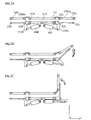
Here Figs. 2A to 2C are schematic sectional views of the
bed showing the operation of actuators in a vicinity of
adjustable stage 20 and lower-back board 11c of bed frame
10. In addition to actuators M1 and M2 used for changing the
shape of bed frame 10, direct-acting actuators M3R/M3L are,
as shown in Figs.2A-2C, disposed symmetrically on adjustable
stage 20 so as to extend respectively to the left and right
of center frame part 21A (i.e. in the y direction toward
coupling members 236Ra/236La, respectively), the head of the
axial parts of actuators M3R/M3L being coupled to L-shaped
members 235R/235L fixed below rotating bars 22R/22L.
According to this structure, L-shaped members 235R/235L and
bars 23R/23L are rotated on the axis of rotating bars 22R/22L
due to the axial parts of actuators M3R/M3L being extended,
which raises side-member support frames 24R/24L from the
horizontal to a position perpendicular with the horizontal
(Figs. 2A→2B→2C).
Stage bars 27R/27L are provided on the underside of side
frame parts 21R/21L, and mate with stage-bar receivers
36R/36L (U-shaped cross-section) on, fixed stage 30.
Stage-bar receivers 36R/36L each have a reverse L-shaped claw
that runs internally in a width direction, adjustable stage
20 being secured in a vertical direction by these claws
hooking around stage bars 27R/27L. When adjustable stage 20
is tilted, the stage bar (i.e. either 27R or 27L) on one side
separates from the stage-bar receiver (i.e. either 36R or
36L).
Adjustable stage 20 and fixed stage 30 can also be
coupled together using the following mechanism. For example,
pole-shaped members (swing bars) that extend in a
longitudinal direction of the bed may be provided on the
underside of side frame parts 32R/32L on fixed stage 30, and
an engaging mechanism provided with respect to the swing bars
that is capable of being locked/unlocked automatically when
the bed is operated. The swing bars are structured to mate
with grips provided on fixed stage 30. The swing bars mate
with the grips when side members 12Ra-12Rd/12La-12Ld are
horizontal, locking the engaging mechanism. Raising the
swing bar on one side when the bed is operated raises the
side members on the corresponding side (i.e. 12Ra-12Rd or
12La-12Ld). This unlocks the engaging mechanism on the side
that is raised, allowing adjustable stage 20 to be tilted.
Since this mechanism enables adjustable stage 20 to
remain securely coupled to fixed stage 30 when the bed is
normally positioned (horizontal), and to be separated from
fixed stage 30 only when necessary, operational safety is
improved.
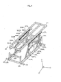
Fig. 4 is a perspective view showing a structure of fixed
stage 30. Fixed stage 30 includes a rectangular frame 31.
The opposing ends of frame 31 form roller- track frame parts
300 and 301, with rollers 200-203 of adjustable stage 20 being
able to travel back and forth along the tops of frame parts
300 and 301. The ends of support arms 354R/356R and 354L/356L
coupled respectively to stage-bar receivers 36R/36L are
fitted into side frame parts 32R/32L so as to have free travel.
Reverse L-shaped rotating arms 351R/352R and 351L/352L
coupled at one end to side frame parts 32R/32L are linked
to support arms 354R/356R and 354L/356L, and horizontal links
353R and 353L are coupled to rotating arms 351R/352R and
351L/352L. Actuators M4R/M4L are disposed at an angle between
stage-bar receivers 36R/36L and horizontal links 353R/353L,
respectively. Parallelogram mechanisms 35R/35L applies as
horizontal slide mechanisms are thus formed on the right and
left sides of fixed stage 30. With parallelogram mechanisms
35R/35L, rotating arms 351R/352R and 351L/352L move in a
circular motion around the points at which they are coupled
to side frame parts 32R/32L, and support arms 354R/356R and
354L/356L travel back and forth at one end on the inside of
side frame parts 32R and 32L, while being regulated by
rotating arms 351R/352R and 351L/352L. Oscillating support
arms 354R/356R and 354L/356L enable adjustable stage 20,
supported by stage-bar receivers 36R/36L, and bed frame 10
to be elevated vertically from both the right and left sides
of fixed stage 30. Consequently, turning bed 1 can be elevated
even in the narrow spaces that result from space saving, while
the use of rollers 200-203 and parallelogram mechanisms 35R
and 35L enables space to be saved even during postural change
operations. Postural changes from a supine to a lateral
position are achieved when one of parallelogram mechanisms
35R/35L corresponding respectively to side frame parts
32R/32L is driven, while a high/low (height adjustment)
mechanism of the bed is realized when parallelogram
mechanisms 35R/35L are driven simultaneously.
Actuators M1/M2 and M3R/M3L are controlled by a CPU 601
and a motor driver 603 in a control unit 600, the caregiver
being able to carry out drive settings (e. g. manual/automatic,
program settings, etc) using a controller (not depicted).
Also, the provision of a cable (cord attached, etc) or
wireless (infrared, etc) remote controller enables settings
to also be performed by the care recipient.
1-2. Operation of Turning Bed (supine → lateral)
A turning bed having the above structure is used with
a mattress placed on bed frame 10. In a normal configuration,
coupled platforms 11a-11d and side members
12Ra-12Rd/12La-12Ld are set, as shown in Fig.1, to be
substantially horizontal.
When a user (a caregiver in the given example) selects,
via the controller, an item relating, for example, to "supine
→ left lateral in flexion position" from a menu and has this
selection executed, actuator M3L attached to adjustable
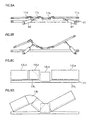
stage 20 is firstly operated, the axial part of actuator M3L
extending outward. L-shaped member 235L coupled to the end
of the axial part and bar 23L rotate around rotating bar 22L,
and side-member support frame 24L rise from a horizontal
position toward a position vertical with the flat surface
of the bed (see Figs . 2A→2B→2C showing actuator operations;
Fig.5 showing side members 12La-12Ld in a raised state;
Fig.8C showing side view of bed in this state).
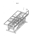
Next, the axial parts of direct-acting actuators M1 and
M2 attached to center frame part 21a of adjustable frame 20
extend out, pushing upper-body and upper-leg boards 11a/11c
of bed frame 10 up from underneath via L-shaped couplers
211/212 to place the care recipient in a flexion position
with upper body raised and knees up (i.e. sitting-up position
and knee break; see Fig.6 showing perspective view of bed
in flexion position; Figs . 8A→8B showing side views of the
bed in this state). The positioning of side member 12La-12Ld
also changes in unison with coupled platforms 11a-11d.
Fan-shaped board 13L comes out from the pocket provided on
side member 12Lc to cover parts of the mattress around the
care recipient's knee region (see Figs. 8C→8D showing side
views of the bed in this state). The tilt angle (i.e. angle
of inclination) of the upper leg when in the flexion position
preferably is set in a range of 10 degrees to 60 degrees
inclusive, since this effectively prevents the care
recipient from rolling in the direction of the incline. A
tilt angle in a range of 20 degrees to 40 degrees inclusive
is more preferable.
When the flexion position with the left side members
raised is achieved as described above, actuator M4R on the
right side of fixed stage 30 operates and the axial part of
the actuator extends outward. As a result, stage-bar receiver
36R and horizontal link 353R separate from one another at
an angle, support arms 354R and 356R slide along the slide
channel in side frame part 32R and rise up, and parallelogram
mechanism 35R operates. Support arms 354R and 356R (or 354L,
356L) thus raise one side of the adjustable stage vertically
upwards as a result of the circular movement of rotating arms
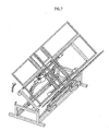
351R and 352R (or 351L, 352L). At the same time, the right
side of adjustable stage 20 is raised to a higher position
than fixed stage 30, rollers 200-203 of adjustable stage 20
roll along the top of roller- track frame parts 300 and 301,
and bed frame 10 tilts toward side frame part 32L of fixed
stage 30; that is, toward the left side of the bed (see Fig. 7
perspective view of bed when tilted). Here, a tilt angle in
a range, for example, of approximately 30 degrees to 70
degrees inclusive is preferable, one example being a tilt
angle of 50 degrees.
As a result of the above transformations in shape of
bed frame 10, the posture of the care recipient is changed
smoothly from a supine to a lateral position while being
supported by coupled platforms 11a-11d and side members
12La-12Ld, after firstly being placed in a supine flexion
position with upper body raised and knees bent. An excellent
posture similar to when a care recipient is turned by the
guiding hand of a caregiver is thus realized.
Since embodiment 1 allows postural changes to be
performed while in a flexion position, which exerts the least
burden on the care recipient's body, the care recipient is
able to comfortably face postural changes, and can look
forward to an easing of the physical discomfort and
psychological anxiety associated with postural changes to
date.
Furthermore, since the caregiver is not required to
perform overly exerting manual tasks when changing the
posture of the care recipient, it is possible for even a
caregiver with little experience to correctly perform
postural changes. By using turning bed 1 of embodiment 1,
the caregiver is thus better able to focus on providing the
best care possible.
1-3. Variation of Turning Bed Operation
1-3-1. Operation Sequence Variation
In the above exemplary operation of embodiment 1, the
care recipient is firstly placed in a Gatch position (i.e.
semi-recumbent with knees elevated to prevent the care
recipient from sliding toward the foot of the bed) after
raising one set of side members (i.e. 12Ra-12Rd or 12La-12Ld),
and then shifted from a supine to a lateral position. However,
the present invention is not limited to this configuration.
For example, a drive sequence may be employed in which the
Gatch position is firstly obtained, as shown in Fig. 9, after
which one set of side members is raised (see Fig. 10, for
example), and then posture changed from a supine to a lateral
position.
Since the posture of the care recipient according to
this drive sequence is changed from the supine position after
first obtaining a semi-recumbent position, it is possible
to avoid any psychological anxiety, such as the
claustrophobic feeling of being hemmed in, that may be caused
by one set of side members suddenly being raised when the
bed is driven, effectively narrowing the space around the
care recipient when still in the supine position. Postural
changes can thus be performed with minimum discomfort.
Furthermore, when, for example, posture is changed to
a right lateral position after firstly obtaining a left
lateral position, it is possible according to this operation
sequence to perform these postural changes continuously from
the left to the right while maintaining the flexion position
(i.e. without first needing to return bed frame 10 to a
horizontally flat state). Consequently, turning from a left
to a right (or right to left) lateral position can be performed
with the care recipient kept in a semi-recumbent position,
thus allowing postural changes to be performed with minimum
discomfort.
1-3-2. Side-Member Pressure Release Control
While the operations of turning bed 1 are fundamentally
designed with the care recipient's safety in mind, the care
recipient may feel tightly constrained by the raised set of
side members (i.e. 12Ra-12Rd or 12La-12Ld). Such feelings
can be alleviated by performing a control to slightly release
the raised set of side members after the postural change is
completed.
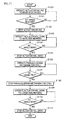
Fig.11 is an exemplary flowchart relating to a
side-member release control for alleviating the feeling of
being constrained. According to the exemplary control shown
in Fig. 11, actuators M1 and M2 are firstly operated in order
to obtain the Gatch position with back and knees raised (step
100), actuators M1 and M2 being operated continuously until
a predetermined angle is reached (step 101). Then, after
stopping actuators M1 and M2 (step 102), actuator M3R or M3L
is operated in order to elevate side members 12Ra-12Rd or
12La-12Ld (step 103), actuator M3R or M3L being operated
continuously until side members 12Ra-12Rd or 12La-12Ld are
angled at 90 degrees (step 104). Then, after stopping
actuator M3R or M3L (step 105), parallelogram mechanism 35R
or 35L is operated in order to tilt adjustable stage 20 (step
106), this being continued until adjustable stage 20 is
tilted at a 50-degree angle (step 107), the drive being
stopped at this exemplary tilt angle of 50 degrees (step 108).
Here, actuator M3R or M3L is operated so as to release
whichever of side members 12Ra-12Rd or 12La-12Ld are bearing
the weight of the care recipient (step 109), the tilt of side
members 12Ra-12Rd or 12La-12Ld being returned from an angle
of 90 degrees to 70 degrees (step 110). The angle here is
not limited to 70 degrees, and may be any angle capable of
supporting the care recipient's body. The operation of
actuator M3R or M3L is stopped when an appropriate angle is
achieved, and the release control ended.
Note that it is possible to perform the operations to
obtain the Gatch position and elevate the side members in
the opposite order to that described above.
1-3-3. Sync Control
The description here relates to an exemplary operation
sequence for operating the side members and parallelogram
mechanisms in synchronization. Since the sync control
sequence enables the above two separate operations to be
performed at the same time, it is possible, in addition to
achieving time reductions, to shift the care recipient's
weight smoothly from the coupled platforms to the side
members, and thus to reduce any psychological burden on the
care recipient that accompanies postural changes.
Fig.12 is a flowchart relating to this sync control
sequence. According to the exemplary control shown in Fig. 12,
actuators M1 and M2 are firstly operated so as to obtain the
Gatch position (step 120), actuators M1 and M2 being operated
continuously until a predetermined angle is reached (step
121). Then, after stopping actuators M1 and M2 (step 122),
CPU 601 calculates the rotation speed of side members
12Ra-12Rd or 12La-12Ld relative to a horizontal direction,
from a roll setting (i.e. adjustable stage 20 tilt angle,
parallelogram mechanism 35R/35L operation speed) when
parallelogram mechanism 35R or 35L is operated (step 123).
Here, CPU 601 calculates the rate of change of the tilt angle
of adjustable stage 20 and the rate of change of the tilt
angle of side members 12Ra-12Rd or 12La-12Ld relative to
platforms 11a-11d. Based on the calculated rates of change,
actuator M3R or M3L is then operated so as to elevate side
members 12Ra-12Rd or 12La-12Ld (step 124), and parallelogram
mechanism 35R or 35L is operated at the same time (step 127).
When the angles of side members 12Ra-12Rd (or 12La-12Ld) and
parallelogram mechanism 35R (or 35L) reach 70 degrees and
50 degrees, respectively, while performing this sync driving,
actuator M3R (or M3L) and parallelogram mechanism 35R (or
35L) are stopped and the sync control ended.
1-4. Turning Bed Safety Mechanisms
The description here relates a number of embodiments
for enabling a turning bed of the present invention to be
used safely.
1-4-1. Safety Mechanism using Load Sensor (1)
Fig.13 is a sectional view of the turning bed. As shown
in Fig.13, support arms (L-shaped cross-section) supported
by fixed stage 30 are provided below bars 23R/23L, and load
sensors S1 and S2 consisting of a micro switch are disposed
on sections of the support arms facing bars 23R/23L. The state
of load sensors S1 and S2 (transmit detection signals showing
respective ON/OFF states) are, as shown in the Fig.14A block
diagram, managed by CPU 601 via an input/output (I/O) circuit
602 in control unit 600. When load sensors S1 and S2 are turned
ON via bars 23R and 23L by the placement of a load on side
members 12Rb/12Lb (i.e. when the care recipient's body is
positioned over side members 12Rb/12Lb), CPU 601, as a safety
measure, instructs motor driver 603 to stop the driving of
actuators M1 and M2, and holds the turning operation in an
OFF state.
Note that it is possible to position the sensors to
correspond with any of side members 12Ra-12Rd and 12La-12Ld.
Also, bars 23R/23L may be replaced members having flexible,
springy properties.
Fig.14B is a flowchart of a specific control relating
to the above safety mechanism. With the exemplary control
shown in Fig.14B, CPU 601 firstly judges whether a command
relating to a postural change operation has been inputted
(i.e. bed has been turned ON) from the controller (step 1).
If the bed has been turned ON, CPU 601 then judges at step
3 whether the detection signal from load sensors S1 and S2
both show the sensors to be OFF (i.e. judgment as to whether
a load is placed over side members 12Rb and 12Lb). If the
sensors are OFF, CPU 601 instructs motor driver 603 to drive
the motors of actuators M1 and M2 (step 4), and the motors
of actuators M1 and M2 are driven based on this instruction
(step 5).
Note that sensors other than micro switches may be
applied in the load sensors, an example of which is a device
using a piezoelectric element.
Furthermore, although CPU 601 is described in the above
example as controlling motor driver 603 to stop the driving
of actuators M1 and M2, the present invention is not limited
to this configuration. The present invention may be
structured so that the turning operations are turned OFF
using circuitry when load sensors S1 and S2 are OFF.
1-4-2. Safety Mechanism using Load Sensor (2)
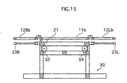
Fig. 15 is a sectional view of the turning bed. As shown
in Fig. 15, load sensors S3, S4, S5 and S6 (S5/S6 not depicted)
consisting of micro switches are disposed between rollers
200-203 of adjustable stage 20 and roller track frames 300
of fixed stage 30. Detection signals (ON/OFF) of load sensors
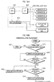
S3-S6 are, as shown in the Fig.16A block diagram, managed
by CPU 601 via I/O circuit 602 in control unit 600. Under
normal conditions, load sensors S3-S6 are ON when in contact
with adjustable stage 20, and turned OFF when adjustable
stage 20 is elevated during the drive of the bed. Load sensors
S3-S6 are provided for the following reason.
Despite actuators M4R/M4L and the like being provided
in parallelogram mechanisms 35R/35L implemented in the
turning bed of embodiment 1, operational errors may exist
in these actuators due to precision variations during
manufacture. Mechanical errors may also exist in
parallelogram mechanisms 35R and 35L themselves, including
the possibility of an operational delay in one of the
actuators when operating parallelogram mechanisms 35R/35L
in sync to elevate platforms 11a-11d in a horizontal position,
or the coupled platforms being tilted at an angle due to the
operation of parallelogram mechanisms 35R/35L not been
smooth. This may cause psychological anxiety to a user lying
on the bed.
Load sensors S3-S6 are provided to suppress the
occurrence of such problems. The following operations, for
example, are possible according to this structure.
As shown in the Fig.16B control flowchart, when the
turning bed is driven, CPU 601 firstly judges at step 10
whether a postural change operation command ("Raise Bed"
operation) has been inputted from the controller (i.e. bed
has been turned ON). If the bed has been turned ON, CPU 601
drives actuator M4R (step 30). Note that actuator M4L is also
driven at this time. Then, if the detection signals from load
sensors S3 and S5 mounted on same side of the bed as actuator
M4R show load sensors S3 and S5 to be ON (i.e. adjustable
stage 20 resting on fixed stage 30), CPU 601 continues to
drive actuator M4R, and when the detection signals show OFF
(i.e. adjustable stage 20 elevated above fixed stage 30 on
the right side of the bed), CPU 601 stops driving actuator
M4R until the detections signal from load sensors S2 and S4
show OFF (step 50, 60). CPU 601 then restarts the driving
of actuator M4R once all of load sensors S3-S6 are OFF. While
this control flowchart relates to actuator M4L drive delays,
the same control flowchart can, of course, also be used to
respond to the case of actuator M4R drive delays.
As such, if the driving of parallelogram mechanism 35R
commences prior to parallelogram mechanism 35L, for example,
detection signals from the load sensors disposed on the same
side as parallelogram mechanism 35R will show OFF. CPU 601,
having acknowledged the OFF state of these load sensors,
stops the operation of parallelogram mechanism 35R and drives
parallelogram mechanism 35L. Then, once the detection
signals from all of load sensors S3-S6 show OFF, CPU again
drives parallelogram mechanism 35R. Thus, with the turning
bed of embodiment 1, parallelogram mechanisms 35R/35L can
be sync driven with greater precision and the bed elevated
while maintaining an extremely flat bed surface, thereby
reducing any psychological anxiety caused to the bed user.
Note that sensors other than micro switches may be
applied in load sensors S3-S6, an example of which is a device
using a piezoelectric element or the like.
Also, load sensors S3-S6 (micro switches) may be OFF
when the bed is in a normal state and turned ON when adjustable
stage 20 is elevated, CPU 601 judging the state of the load
sensors on this basis. This configuration is most preferable
in terms of providing a safe feel.
Furthermore, the present invention is not limited to
the above exemplary provision of four load sensors S3-S6.
The number of load sensors may be other than four, an example
of which is the provision of one load sensor on the right
and left sides at the head or foot of the bed.
1-4-3. Safety Mechanisms of Turning Bed
In the example shown in embodiment 1, rollers 200-203
roll along the top of roller track frame parts 300 and 301,
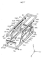
although it is possible to provide viscosity-generating
means corresponding to rollers 200-203, an example being
so-called rotary viscous dampers, which are rotary-type
speed controllers that use oil pressure (hydraulic). Fig. 17
shows an exemplary configuration in which rotary dampers
361-364 and racks 365 and 366 that mesh with the dampers are
attached in a vicinity of rollers 200-203.
According to this configuration, control is exerted on
the rotary action of rollers 200-203 by rotary dampers
361-364 mounted thereto when, for example, parallelogram
mechanism 35R is operated during the driving of the turning
bed, allowing for gentle and smooth rotation with a high
degree of stability, and thus for turning operations to be
performed safely.
Of course, the viscosity-generating means may be other
than rotary dampers 361-364. For example, it is possible to
employ rotation-speed controller mechanisms such as known
friction clutch mechanisms or centrifugal brake mechanisms
in same locations as rotary rollers 361-364. Also, rotary
dampers 361-364 can be formed integrally with respective
rollers 200-203.
1-5. Related Matters
In the example given in embodiment 1, the middle and
side parts of the bed frame are each divided into four sections
in a longitudinal direction, and these sections are coupled
together. The present invention is, of course, not limited
to this configuration, it being possible to divide the bed
frame into a different number of sections. However, the
platform, when structured from a coupled frame as in
embodiment 1, preferably is divided into four or more
sections corresponding to the upper body, lower back, and
upper/lower leg regions, since this allows for subtle
adjustment of the bed frame so as to at least accommodate
postural changes when the care recipient is sleeping, for
example.
Also, the side members may also be divided in the
longitudinal direction (x direction) and the resultant
sections linked together, thus allowing postural changes to
be carried out while cradling the care recipient to provide
support.
Furthermore, although direct-acting actuators are used
in the example given in embodiment 1, other actuator drive
methods may be used, an example of which is a rotational method.
Also, other driving sources may be used, examples of which
include actuators that operate using pneumatic or hydraulic
methods, for example.
Furthermore, although the description in embodiment 1
only relates to postural changes from a supine to a left
lateral position, it is, of course, possible to similarly
perform postural changes in the opposite direction or from
supine to right lateral positions.
Furthermore, turning bed 1 of embodiment 1 is not
limited only to care recipients such as bedridden patients,
and can also be used as a general-purpose bed.
Furthermore, since the mechanism consisting of coupled
platforms 11a-11d and actuators M1 and M2 for obtaining a
flexion position is disposed independently of parallelogram
mechanisms 35R and 35L on either side of turning bed 1, it
is also possible to drive these mechanisms selectively in
order to separately raise the back/knees or tilt/elevate the
bed surface.
Note that although in the embodiment 1 example, the
controller of the turning bed was an infrared type or a
cable/wireless type having a cord, the present invention is
not limited to this configuration, it being possible to
perform drive controls using speech recognition.
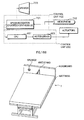
Fig .18A is a block diagram showing a configuration for
performing drive controls using speech recognition. The
speech recognition unit, as one example, includes a
microphone 702 as an input device and a speaker 703 as an
output device, and is constituted from a control unit 700
that includes a speech recognition device 701 consisting of
a single-chip microcomputer, and control unit 600 that
includes CPU 601 and motor driver 603 for driving the
actuators. Speaker 703 is provided for announcing operations
to the bed user before the operations are performed. A
predetermined number of vocabularies (e.g. "tilt to left",
"raise head", etc) for instructing the various operations
of turning bed 1 are prestored in a memory included in speech
recognition device 701, and various operation instructions
corresponding to these vocabularies are sent to CPU 601.
Furthermore, words that reflect slight variations in
pronunciation from the predetermined vocabularies are also
supplementarily stored in memory, so as to enable speech
recognition device 701 to respond when there are slight
errors/differences in the inputted words (e.g. the
instruction "lower head" being inputted as "lower 'ead" with
the consonant "h" dropped), thus enabling operation that
allows for such errors/differences.
On the other hand, Fig.18B is a perspective view of a
turning bed having a microphone (speech recognition input
device) attached thereto. Schematically shown in the present
embodiment is a configuration in which platform 11a at the
head of the bed, to which a headboard is fitted, is equipped
with a microphone having a flexible stand. This allows the
microphone to always be positioned close to the care
recipient's mouth even when the bed is driven. Here, a
lavalier microphone may be used in place of the microphone
stand.
Fig.19 shows an exemplary structural improvement in a
vicinity of platform 11d. Platform 11d and adjustable stage
20 shown in Fig.19 are coupled together with slide-roller
mechanisms 115R/115L provided therebetween. This
effectively prevents any play between platform 11d and
adjustable stage 20. Note that although the structure in a
vicinity of platform 11d shown in Fig.19 differs from that
shown in Fig.1, the fundamental structure of the bed is the
same.
At the foot end of adjustable stage 20 shown in Fig.19,
side frame parts 21R/21L are fixed in place by two frame parts
210 and 211, which are in turn secured in place by frame parts
212R/212L. On platform 11d are disposed rollers 113R/113L,
which are fitted into slide channels 213R/213L on frame parts
212R/212L so to travel back and forth within the channels.
Two frame parts 111R/111L are disposed on the inside
of frame parts 110R/110L, which form the outer frame of
platform 11d, and rollers 113R/113L are attached to frame
parts 111R/111L via triangular slide chips 112R/112L and
roller stands 114R/1L4L. While rollers 113R/113L are
normally (i.e. bed in horizontal position) removed from slide
channels 213R/213L, when the bed is driven the sloped surface
of slide chips 112R/112L comes in contact with slide blocks
116R/116L and rollers 113R/113L fit into slide channels
213R/213L. Slide chips 112R/112L and slide blocks 116R/116L
are made from a hard resin material having favorable sliding
properties.
The operations when using the above slide roller
mechanisms 115R/115L are as shown in the partial sectional
views of the bed in Figs.20A-20D. Under normal conditions
(i.e. horizontal bed), rollers 113R/113L are positioned
freely outside of slide channels 213R/213L when forming a
flat bed surface (Fig.20A) , and then as platform 11d inclines
to form the Gatch position, the sloped surface of slide chips
112R/112L slide over slide blocks 116R/116L (Fig.20B). As
the slope of platform 11d becomes steeper, rollers 113R/113L
fit into slide channels 213R/213L with the sloped surface
of slide chips 112R/112L being guided by slide blocks
116R/116L. The load bearing thus shifts from slide chips
112R/112L to rollers 113R/113L (Fig.20C). Rollers 113R/113L
then slide along slide channels 213R/213L, allowing a
favorable Gatch position to be formed without platform 11d
suddenly separating from fixed stage 20 (Fig.20D).
Accordingly, slide roller mechanisms 115R/115L may be
provided in the present invention to stabilize bed
operations.
1-6. Turning Bed Mattress
Described here is an exemplary construction of a
mattress suitable for use with a turning bed as described
above.
1-6-1. Mattress formed from Composite Material
Fig. 21 shows an exemplary construction of a turning bed
mattress. Mattress 400, which is basically made from a
urethane material, has a hybrid structure formed from a
composite material in which a relatively soft material is
used for a section 401, which corresponds to platforms
11a-11d of the turning bed, and a relatively hard material
used for sections 402R/402L, which correspond to side members
12Ra-12Rd/12La-12Ld.
By using mattress 400 having this construction, it is
firstly possible to support the posture of a care recipient
lying horizontally on the mattress using section 401 of the
mattress surface made from the relatively soft material.
Secondly, when the bed is driven, the care recipient can
expect postural changes to be performed while being gently
supported, as a result of sections 402R/402L of the mattress
surface being made from the relatively hard material giving
to fit the shape of the side of the body.
1-6-1. Mattress with Alignment Mark
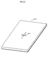
Fig. 22 shows an exemplary construction of a turning bed
mattress. On a surface of mattress 410 is disposed an
alignment mark 411 in the shape of a cross that marks a
position corresponding to the care recipient's buttock
region, thus enabling the care recipient to lie in an optimal
position. Alignment mark 411 may be printed, embroidered,
or the like on the mattress. This additional measure results
in a turning bed of the present invention capable of
performing even safer and more effective postural changes.
The pattern of alignment mark 411 may, of course, be other
than that shown in Fig.22. Also, an alignment mark may be
printed on a mattress sheet or the like.
1-6-3. Mattress having Slits
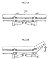
Figs.22A and 22B are sectional views showing an
exemplary construction of a turning bed mattress. As shown
in these diagrams, mattress 420 has slits 421 and 422 formed
in a thickness direction thereof, the position of the slits
corresponding to the joints coupling platforms 11 to side
members 12R/12L,
According to this construction, slits 421 and 422 in
mattress 420 open up when side members 12R or 12L are raised,
forming a mattress surface having a natural slope by smooth
operations, and facilitating postural changes.
1-6-4. Mattress having Hooks
Fig. 24 shows an exemplary construction of the underside
of a turning bed mattress. A characteristic of mattress 430
shown in this diagram is the attachment of hooks 431R/431L
on both sides of the mattress at positions corresponding to
the knee region (i.e. side members 12Rc/12Lc) when the care
recipient is lying down, these hooks being designed to mate
with the meshed surface of side members 12Rc/12Lc.
Since the sides of mattress 430 are secured to the
surfaces of side members 12Rc/12Lc according to this
construction, problems arising from the movement of
platforms 11a-11d and side members 12Ra-12Rd/12La-12Ld when
the bed is driven, such as the mattress being pinched between
the joints of bed frame 10, are favorably avoided, thus making
it possible to suppress operational errors and perform smooth
postural changes.
While hooks 431R/431L may be provided at positions
other than the edge of mattress 430, the positions shown in
Fig.24 are preferable since they most effectively prevent
pinching of the mattress. Also, hooks 431R/431L may be
provided on a sheet or the like covering mattress 430, rather
than directly on mattress 430. Since sheets are more likely
to get pinched than mattress 430, this configuration makes
it possible to effectively resolve problems relating to
pinching.
2. Embodiment 2
Fig.25A is a perspective view showing a structure of
a turning bed in an embodiment 2.
While the bed structure in embodiment 1 is driven using
parallelogram mechanisms, in embodiment 2, direct-acting
actuators are disposed vertically, and side members on the
left or right are elevated vertically using elevation
mechanisms, thus enabling platforms positioned above an
adjustable stage to be titled.
With the turning bed of embodiment 2, a pair of columnar
direct-acting actuators is disposed within a rectangular
fixed stage, and a bed frame supported by an adjustable stage
is positioned on top of the actuators. The platforms, as in
embodiment 1, are constructed as coupled platforms that are
coupled together by a plurality of joints corresponding to
the care recipient's upper body, hip, upper leg, and lower
leg regions. Of these, the section corresponding to the
upper-leg board is secured to the adjustable frame, which
has a frame construction equivalent to the overall size of
the platforms. Provided on the underside of the platforms
is a drive unit that includes an actuator mechanism for
forming a flexion position.
Side members are disposed above the columnar
direct-acting actuators. Housing slots are formed in the side
members. Here, the housing slots are partitioned in a
longitudinal direction of the bed, and pullout sidewalls that
are coupled to one another are housed in the housing slots.
The side members are coupled to the adjustable stage
supporting the platforms via the pullout sidewalls. The
pullout sidewalls are biased in the direction of the housing
slots by tension springs or the like, and are automatically
housed in the housing slots when a force pulling the pullout
sidewalls out of the housing slots weakens.
With a turning bed having the above structure, a flexion
position is firstly formed using the coupled platforms when
the bed is driven, as shown in Fig.25B. One of the columnar
direct-acting actuators then operates to lower the set of
side members positioned thereabove. This has the effect of
tilting the adjustable stage, which also brings the coupled
platforms down at an angle. This results in the pullout
sidewalls being pulled toward the coupled platforms from the
respective housing slots at the lowered end of the tilted
adjustable stage, raising the pullout sidewalls relative to
the coupled platforms; that is, the pullout sidewalls at the
lower end hangs from the coupled platforms with the angle
between the two narrowed. At the same time, the side members
housing these pullout sidewalls are placed in a raised state
relative to the coupled platforms. This achieves the effect
of supporting the side of the care recipient's body with the
pullout sidewalls while keeping the care recipient in the
flexion position, thereby allowing for postural changes to
be performed excellently, as in embodiment 1.
3. Embodiment 3
Figs.26A to 26F show a structure of a turning bed in
an embodiment 3.
The turning bed in embodiment 3, which can be used with
general-purpose beds, is constituted by laying an air
mattress formed from a plurality of airbags on a
general-purpose bed. A characteristic of this turning bed
is the use of an air pump (not depicted) to supply/discharge
air independently for each airbag via an air hose. The air
hose has a valve that is controlled to open/close by a control
unit (not depicted), thus controlling the
inflation/deflation of respective airbags . The airbags are,
as one example, partitioned into upper body (double layer),
lower back (double layer), upper leg, lower leg, and both
sides of the bed so as to correspond to the joints of the
care recipient's body.
A turning bed having the above structure is normally
used with a mattress or the like placed over the air mattress.
When turning the care recipient from a supine to a lateral
position, the upper airbags on both sides of the bed are
firstly inflated (Fig.26A→26C). Next, the care recipient is
placed in the flexion position by tilting the airbags
corresponding to the upper body and lower back in a
longitudinal direction, and inflating the airbags
corresponding to the upper and lower leg regions so as form
a knee break (Fig.26D). It is then possible to turn the care
recipient to either the left or right lateral positions while
maintaining the flexion position by deflating the airbag on
either the left or right side, and inflating the lower of
the two airbags corresponding to the upper body and lower
back (Fig.26E, 26F). According to this configuration,
embodiment 3 achieves substantially the same effects as
embodiments 1 and 2.
Note that while embodiment 3 shows an example using a
general-purpose bed, the excellent portability of embodiment
3 means that the above turning bed can, in addition to being
applied to a variety of general-purpose beds, also be laid
directly on the floor (i.e. directly over tatami, carpet or
the like).
4. Safety Fittings
Described here are safety fittings suitable for use
with a turning bed as in the above embodiments.
4-1. Pillow, Armrest, Legrest
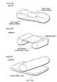
Fig.27A shows a pillow for use with a turning bed. A
middle part of the pillow is depressed relative to the both
sides, this depression being designed to fit the care
recipient's head.
According to this structure, it is possible to
stabilize the care recipient's head using the middle part
of the pillow when the bed is stationary. Then, during the
driving of the bed, the sides of the head are gently supported
when the bed is tilted to either side and the care recipient's
spine is kept substantially straight, enabling smooth
postural changes to be performed.
Next, Fig.27B shows an armrest (cushion) for use with
a turning bed. This armrest is formed from left and right
columnar elbow-rest pads coupled to a band-shaped sheet. To
use the armrest, the sides of the care recipient when lying
on the bed are placed between the elbow-rest pads. In addition
to supporting the care recipient's position on the bed to
a certain degree, use of this armrest for a turning bed can
also be expected to effectively prevent the care recipient
from being sandwiched/pressed in on the sides when the bed
is driven.
Fig. 27C shows a legrest (cushion) for use with a turning
bed. This legrest is formed from a columnar knee/ankle pad
joined to a band-shaped calf pad. To use the legrest, the
knee/ankle pad is sandwiched between both legs and the calves
are positioned on the calf pad so that the care recipient's
heels are suspended above the bed surface. Use of this legrest
allows the care recipient's knees and ankles to be kept
together at all times whether the bed is stationary or moving,
effectively preventing the occurrence of decubitus ulcers.
The load on the care recipient's heels is also lightened,
effectively preventing decubitus ulcers in the heel region.
4-2. Gloves
Figs. 28A to 28C show gloves for use with a turning bed.
These gloves are secured safely in front of the care recipient,
so as not to interfere with arm movement when the turning
bed is driven. The methods for securing the gloves include,
as shown in the diagrams, lining them up side-by-side in a
width direction of the bed (Fig.28A/28B), and arranging them
together in a longitudinal direction of the bed (Fig.28C).
The gloves preferably are used together with the above
armrest to increase effectiveness.
INDUSTRIAL APPLICABILITY
An adjustable bed according to the present invention
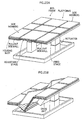
can be used as a nursing care bed or a reclining bed.