US11470980B2 - Multi-function device for an adjustable bed system - Google Patents
Multi-function device for an adjustable bed system Download PDFInfo
- Publication number
- US11470980B2 US11470980B2 US16/108,305 US201816108305A US11470980B2 US 11470980 B2 US11470980 B2 US 11470980B2 US 201816108305 A US201816108305 A US 201816108305A US 11470980 B2 US11470980 B2 US 11470980B2
- Authority
- US
- United States
- Prior art keywords
- adjustable bed
- bed system
- control box
- function device
- button
- Prior art date
- Legal status (The legal status is an assumption and is not a legal conclusion. Google has not performed a legal analysis and makes no representation as to the accuracy of the status listed.)
- Active, expires
Links
Images


Classifications
-
- A—HUMAN NECESSITIES
- A47—FURNITURE; DOMESTIC ARTICLES OR APPLIANCES; COFFEE MILLS; SPICE MILLS; SUCTION CLEANERS IN GENERAL
- A47C—CHAIRS; SOFAS; BEDS
- A47C21/00—Attachments for beds, e.g. sheet holders or bed-cover holders; Ventilating, cooling or heating means in connection with bedsteads or mattresses
- A47C21/003—Lighting, radio, telephone or the like connected to the bedstead
-
- A—HUMAN NECESSITIES
- A47—FURNITURE; DOMESTIC ARTICLES OR APPLIANCES; COFFEE MILLS; SPICE MILLS; SUCTION CLEANERS IN GENERAL
- A47C—CHAIRS; SOFAS; BEDS
- A47C17/00—Sofas; Couches; Beds
- A47C17/04—Seating furniture, e.g. sofas, couches, settees, or the like, with movable parts changeable to beds; Chair beds
-
- A—HUMAN NECESSITIES
- A47—FURNITURE; DOMESTIC ARTICLES OR APPLIANCES; COFFEE MILLS; SPICE MILLS; SUCTION CLEANERS IN GENERAL
- A47C—CHAIRS; SOFAS; BEDS
- A47C20/00—Head-, foot- or like rests for beds, sofas or the like
- A47C20/04—Head-, foot- or like rests for beds, sofas or the like with adjustable inclination
- A47C20/041—Head-, foot- or like rests for beds, sofas or the like with adjustable inclination by electric motors
-
- A—HUMAN NECESSITIES
- A47—FURNITURE; DOMESTIC ARTICLES OR APPLIANCES; COFFEE MILLS; SPICE MILLS; SUCTION CLEANERS IN GENERAL
- A47C—CHAIRS; SOFAS; BEDS
- A47C31/00—Details or accessories for chairs, beds, or the like, not provided for in other groups of this subclass, e.g. upholstery fasteners, mattress protectors, stretching devices for mattress nets
- A47C31/008—Use of remote controls
-
- H—ELECTRICITY
- H01—ELECTRIC ELEMENTS
- H01R—ELECTRICALLY-CONDUCTIVE CONNECTIONS; STRUCTURAL ASSOCIATIONS OF A PLURALITY OF MUTUALLY-INSULATED ELECTRICAL CONNECTING ELEMENTS; COUPLING DEVICES; CURRENT COLLECTORS
- H01R25/00—Coupling parts adapted for simultaneous co-operation with two or more identical counterparts, e.g. for distributing energy to two or more circuits
- H01R25/006—Coupling parts adapted for simultaneous co-operation with two or more identical counterparts, e.g. for distributing energy to two or more circuits the coupling part being secured to apparatus or structure, e.g. duplex wall receptacle
-
- H—ELECTRICITY
- H01—ELECTRIC ELEMENTS
- H01R—ELECTRICALLY-CONDUCTIVE CONNECTIONS; STRUCTURAL ASSOCIATIONS OF A PLURALITY OF MUTUALLY-INSULATED ELECTRICAL CONNECTING ELEMENTS; COUPLING DEVICES; CURRENT COLLECTORS
- H01R13/00—Details of coupling devices of the kinds covered by groups H01R12/70 or H01R24/00 - H01R33/00
- H01R13/66—Structural association with built-in electrical component
- H01R13/70—Structural association with built-in electrical component with built-in switch
- H01R13/701—Structural association with built-in electrical component with built-in switch the switch being actuated by an accessory, e.g. cover, locking member
-
- H—ELECTRICITY
- H01—ELECTRIC ELEMENTS
- H01R—ELECTRICALLY-CONDUCTIVE CONNECTIONS; STRUCTURAL ASSOCIATIONS OF A PLURALITY OF MUTUALLY-INSULATED ELECTRICAL CONNECTING ELEMENTS; COUPLING DEVICES; CURRENT COLLECTORS
- H01R13/00—Details of coupling devices of the kinds covered by groups H01R12/70 or H01R24/00 - H01R33/00
- H01R13/66—Structural association with built-in electrical component
- H01R13/717—Structural association with built-in electrical component with built-in light source
-
- H—ELECTRICITY
- H01—ELECTRIC ELEMENTS
- H01R—ELECTRICALLY-CONDUCTIVE CONNECTIONS; STRUCTURAL ASSOCIATIONS OF A PLURALITY OF MUTUALLY-INSULATED ELECTRICAL CONNECTING ELEMENTS; COUPLING DEVICES; CURRENT COLLECTORS
- H01R13/00—Details of coupling devices of the kinds covered by groups H01R12/70 or H01R24/00 - H01R33/00
- H01R13/73—Means for mounting coupling parts to apparatus or structures, e.g. to a wall
-
- H—ELECTRICITY
- H01—ELECTRIC ELEMENTS
- H01R—ELECTRICALLY-CONDUCTIVE CONNECTIONS; STRUCTURAL ASSOCIATIONS OF A PLURALITY OF MUTUALLY-INSULATED ELECTRICAL CONNECTING ELEMENTS; COUPLING DEVICES; CURRENT COLLECTORS
- H01R24/00—Two-part coupling devices, or either of their cooperating parts, characterised by their overall structure
- H01R24/60—Contacts spaced along planar side wall transverse to longitudinal axis of engagement
- H01R24/62—Sliding engagements with one side only, e.g. modular jack coupling devices
-
- H—ELECTRICITY
- H01—ELECTRIC ELEMENTS
- H01R—ELECTRICALLY-CONDUCTIVE CONNECTIONS; STRUCTURAL ASSOCIATIONS OF A PLURALITY OF MUTUALLY-INSULATED ELECTRICAL CONNECTING ELEMENTS; COUPLING DEVICES; CURRENT COLLECTORS
- H01R25/00—Coupling parts adapted for simultaneous co-operation with two or more identical counterparts, e.g. for distributing energy to two or more circuits
- H01R25/003—Coupling parts adapted for simultaneous co-operation with two or more identical counterparts, e.g. for distributing energy to two or more circuits the coupling part being secured only to wires or cables
-
- H—ELECTRICITY
- H04—ELECTRIC COMMUNICATION TECHNIQUE
- H04W—WIRELESS COMMUNICATION NETWORKS
- H04W12/00—Security arrangements; Authentication; Protecting privacy or anonymity
- H04W12/06—Authentication
Definitions
- This disclosure relates to adjustable beds and adjustable bed frames and more particularly to an adjustable bed system having a multi-function device incorporated with the adjustable bed system.
- Conventional beds may consist of a mattress, a box spring, a headboard, a foot board, a pair of spaced apart bed rails, and longitudinally spaced, transversely extending wooden or metal slats extending between the bed rails.
- the slats and the bed rails are used to support the mattress and box spring above the floor upon which the bed is positioned.
- adjustable beds have been developed. Some adjustable beds are used for medical reasons such as aiding recovery for an individual.
- An adjustable bed may consist of one or more sections that may be moved or adjusted during use by employing actuators or motors to move the sections.
- adjustable beds are operated by use of a wired control or a wireless remote control that are part of the adjustable bed and are connected to a control box. Although such adjustable beds are available and useful, it is difficult or impossible to interact with the control box to control some features associated with the adjustable bed. For example, it may be necessary to synchronize various devices with the control box. However, it may be difficult or impractical to reach the control box. In view of this, a better and user friendly system to operate adjustable beds through the use of a multi-function device may be desired.
- the present disclosure is designed to obviate and overcome many of the disadvantages and shortcomings associated with conventional adjustable beds.
- the present disclosure provides a multi-function device or unit that is incorporated into an adjustable bed system that is used to control certain operations of a control box associated with the adjustable bed system. It would also be advantageous to have a multi-function device or unit that is not complex and is easy to use in order to operate the adjustable bed system.
- the present multi-function device is applicable for use with full, queen, California kings, and king size adjustable bed systems.
- a multi-function device for an adjustable bed system comprises a housing having a top section and a side section, the side section having a button having a light and a port, operation of the button for sending a signal, a cord connected to the housing, the cord having a wire connected to the button, and a connector connected to the wire.
- a multi-function device for an adjustable bed system comprises a housing having a top section and a side section, the side section having a button having a light and a port, operation of the button for sending a signal, a central body housing having a first side, a back side, an extension portion along the back side, a second side, and a lid to cover the central body housing, a cord connected to the housing, the cord having a wire connected to the button, and a connector connected to the wire.
- a multi-function device for an adjustable bed system comprises a housing having a top section and a side section, the side section having a button having a light and a port, operation of the button for sending a signal, a cord connected to the housing, the cord having a wire connected to the button, and a connector connected to the wire, and an adjustable bed system having a control box having a plug, the connector for insertion into the plug, the signal for placing the control box into a mode of operation.
- the present disclosure provides a multi-function device for an adjustable bed system that may be used to operate various functions associated with an adjustable bed.
- the present disclosure provides a multi-function device for an adjustable bed system which can be easily employed and operated with highly reliable results.
- the present disclosure is also directed to a multi-function device for an adjustable bed system that responds to various input commands to operate various functions associated with an adjustable bed.
- the present disclosure also provides a multi-function device for an adjustable bed system which includes one or more USB (universal serial bus) ports.
- USB universal serial bus
- the present disclosure provides a multi-function device for an adjustable bed system that is capable of being incorporated into the adjustable bed system and can be easily operated without the use of any specialized equipment.
- the present disclosure also provides a multi-function device for an adjustable bed system that controls various operations associated with an adjustable bed.
- the present disclosure provides a multi-function device for an adjustable bed system that is employed to assist an individual to adjust and operate the adjustable bed system.
- the present disclosure is directed to a multi-function device for an adjustable bed system in which the multi-function device is positioned so that the multi-function device may be accessed even when the adjustable bed system is operating.
- the present disclosure is further directed to a multi-function device for an adjustable bed system in which the multi-function device is capable of being accessed regardless of the position of the adjustable bed system.
- the present disclosure also provides a multi-function device for an adjustable bed system that provides feedback concerning various operations of the adjustable bed system.
- the present disclosure further provides a multi-function device for an adjustable bed system that may be used with any sized mattress such as a full, twin, queen, California king, and king sized mattress.
- the present disclosure is also directed to a multi-function device for an adjustable bed system that comprises a module or unit that may be constructed as part of the adjustable bed system.
- FIG. 1 is a front perspective view of a multi-function device for an adjustable bed system constructed according to the present disclosure
- FIG. 2 is a bottom perspective view of the multi-function device for an adjustable bed system constructed according to the present disclosure
- FIG. 3 is a side perspective view of the multi-function device for an adjustable bed system installed in the adjustable bed system with the adjustable bed system being in an adjusted position;
- FIG. 4 is a side perspective view of the multi-function device for an adjustable bed system installed in the adjustable bed system with the adjustable bed system being in a relaxed or original position;
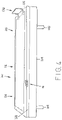
- FIG. 5 is an enlarged perspective view of the multi-function device for an adjustable bed system installed in the adjustable bed system.
- FIG. 6 is a schematic block diagram of the multi-function device for an adjustable bed system constructed according to the present disclosure.
- the multi-function device for an adjustable bed system 10 is shown comprising a device housing 12 having an upper portion 14 and a side portion 16 .
- the side portion 16 has a button 18 that has a light 20 and a first USB (Universal Serial Bus) port 22 and a second USB port 24 .
- USB ports 22 and 24 are shown, it is possible that the ports may be USB-B, Mini-USB, Micro-USB type, as required by the particular application.
- a cord 26 extends out from the device housing 12 and has an end 28 having a plug or connector 30 .
- the cord 26 can be any suitable length and will typically be long enough to have the connector 30 connected to a control box (not shown) associated with an adjustable bed system (also not shown).
- the housing 12 and the portions 14 and 16 may be constructed of any suitable material with plastic being a preferred material.
- the light 20 may be illuminated to indicate one or more modes associated with the multi-function device 10 , as will be discussed further herein.
- the housing 12 also has an outer cover plate 32 and an inner cover plate 34 .
- FIG. 2 is a bottom perspective view of the multi-function device for an adjustable bed system 10 constructed according to the present disclosure.
- the device 10 has the device housing 12 having the upper portion 14 and the side portion 16 .
- the device housing 12 also has a central body housing 36 having a first side 38 , a back side 40 , an extension portion 42 along the back side 40 , and a second side 44 .
- a lid 46 is used to cover the central body housing 36 .
- the lid 46 may have a number of screw holes 48 for receiving screws 50 to secure the lid 46 to the central body housing 36 .
- the extension portion 42 has a first side 52 , a back side 54 , and a second side 56 .
- the back side 54 may have an opening 58 in which a grommet or a strain relief connector 60 may be inserted to hold or secure the cord 26 in place.
- the device housing 12 also has a first clip 62 and a second clip 64 .
- the clips 62 and 64 are used to secure the device housing 12 to an adjustable bed system (not shown), as will be explained further herein.
- the plug 30 has the end 28 having a number of sockets 66 which are adapted to fit into a port (not shown) associated with a control box (also not shown).
- the sockets 66 are connected to wires (not shown) within the cord 26 .
- the sockets 66 allow data, signals, pulses, or frequencies to be provided from the button 18 or the USB ports 22 and 24 to the control box.
- the sockets 66 also allow power to be provided from the control box to the USB ports 22 and 24 or the light 20 .
- the adjustable bed system 100 has a base 102 being supported by legs 104 , 106 , 108 , and 110 .
- the base 102 has an adjustable bed frame 112 having a head section 114 , a mid section 116 , and a foot section 118 .
- the head section 114 may be adjusted or articulated by use of motor 120 and arms 122 .
- the arms 122 are connected between the head section 114 and the motor 120 . Operation of the motor 120 will cause movement of the arms 122 which in turn may raise or lower the head section 114 as desired.
- the foot section 118 may also have a motor 124 and arms 126 .
- An individual operating the system 100 may control movement of the foot section 118 through operation of the motor 124 to move the arms 126 to raise or lower the foot section 118 .
- the multi-function device 10 is shown installed on a side 128 of the head section 114 .
- the device 10 has the button 18 and the ports 22 and 24 present for an individual to be able to press the button 18 or to insert various cords into the ports 22 and 24 .
- a smart phone may be connected to the port 22 to charge the smart phone through use of the USB port 22 .
- other devices such as a laptop or a tablet, may also be connected to the port 22 for charging purposes.
- the adjustable bed system 100 may have various other components positioned within the base 102 .
- a control box (not shown) may be housed within the base 102 and the plug 30 may be connected into the control box. In this manner, the cord 26 and the plug 30 are not easily accessible to a user of the adjustable bed system 100 and the cord 26 and the plug 30 are not in the way.
- FIG. 4 illustrates the adjustable bed system 100 in an original position in which the head section 114 and the foot section 118 have not been raised.
- the adjustable bed system 100 is shown having the base 102 being supported by legs 104 and 108 .
- the base 102 has the adjustable bed frame 112 having the head section 114 , the mid section 116 , and the foot section 118 .
- the motors 120 and 124 and the arms 122 and 126 are not visible because the adjustable bed frame 112 is in the original position.
- the adjustable bed system 100 also has a bracket 130 attached at a foot 132 of the bed frame 112 in the foot section 118 to prevent a mattress (not shown) that may be placed on the bed frame 112 from falling off of the bed frame 112 .
- the multi-function device 10 is shown installed on the side 128 of the head section 114 .
- the adjustable bed system 100 may include other features or components such as, by way of example only, a lumbar support device, a massage device for vibrating a mattress, and one or more lights for illuminating various areas of the adjustable bed system 100 .
- the adjustable bed system 100 allows for the adjustable bed frame 112 and in turn a mattress to be put into different positions.
- the adjustable bed system 100 may be adjusted to prop up a head of an individual to view television or to read a book, or elevate legs of the individual for comfort, or sleep in a zero gravity position for further comfort.
- the adjustable bed system 100 may have other features and components such as a wired handheld control, a wireless remote control, reading or night lights, a wave function device, a timer device, various movable and stationary frame members, solenoids, and linkages to connect the motors 120 and 124 to various other movable frame members.
- the adjustable bed system 100 may be any size and shape so as to contain or support conventionally available mattresses such as a full, queen, California king, or king sized mattress.
- FIG. 5 an enlarged view of the multi-function device 10 being inserted into the side 128 of the head portion 114 of the bed frame 112 is shown.
- the multi-function control device 10 has the button 18 surrounded by the light 20 and the USB ports 22 and 24 .
- the device housing 12 has the side portion 16 fitted into the side 128 and the upper portion 14 is fitted into a top surface 134 of the head portion 114 of the bed frame 112 .
- the device 10 is flush with the side 128 and the top surface 134 to be easily accessible by an individual using the device 10 .
- the ports 22 and 24 are readily accessible so that a device, such as a smart phone, may be plugged into the ports 22 and 24 .
- FIG. 6 illustrates a schematic block diagram of the multi-function device 10 and the adjustable bed system 100 .
- the device 10 has the button 18 connected through the cord 26 to the connector 30 via a wire 150 . Once the button 18 is pressed a signal will be sent over the wire 150 to the connector 30 .
- the connector 30 is inserted into a connector 152 of a control box 154 of the adjustable bed system 100 .
- the control box 154 is used to control various functions of the adjustable bed system 100 .
- the adjustable bed system 100 may also have a remote control 156 .
- the light 20 is also connected to the connector 30 by a wire 158 .
- the first USB port 22 is connected to the connector 30 by a wire 160 .
- the second USB port 24 is connected through the cord 26 to the connector 30 by a wire 162 .
- all of the wires 150 , 158 , 160 , and 162 are within the cord 26 .
- single wires 150 , 158 , 160 , and 162 are shown for purposes of clarity, it should be understand that multiple wires may be used to connect the various components of the device 10 to the adjustable bed system 100 .
- the multi-function device 10 operates in the following manner.
- the button 18 When the button 18 is pressed and held for five seconds, the adjustable bed system 100 will allow the remote 156 to be synced to the control box 154 .
- This is known as remote pairing mode.
- the remote 156 may control various functions of the adjustable bed system 100 .
- the remote 156 may have buttons in which the head section 114 may be adjusted up or down or the foot section 118 may be adjusted up or down.
- the button 18 is pressed once movement of the adjustable bed system 100 will be halted. In essence, by pressing the button 18 once the multi-function device 10 incorporates an emergency stop function to stop operation of the adjustable bed system 100 .
- the adjustable bed system 100 may be connected by a WiFi (wireless fidelity) connection to another device such as an Amazon Echo device, an Amazon Echo Dot device, a Google Home device, or an Apple HomePod.
- WiFi wireless fidelity
- the device 10 allows easy and quick access to the control box 154 of the adjustable bed system 100 .
- the light 20 provides visual feedback that the adjustable bed system 100 has entered into the various modes of operation. In particular, when the button 18 has been pressed four times to place the system 100 into the access point mode, the light 20 will blink until pairing is successful. Once pairing has been successful the light 20 will be extinguished or turned off. Also, when the button 18 has been held for five seconds placing the system 100 into remote pairing mode, the light 20 will blink until remote pairing has been successful. Again, once remote pairing has been successfully completed the light 20 will be turned off. Further, any device that may be connected into the USB ports 22 and 24 may be connected so that the device may be charged by the adjustable bed system 100 . When the button 18 is pressed and held for fifteen seconds this puts the control box 154 into a mode of operation in which a standard remote control may be synced to the control box 154 .
Landscapes
- Health & Medical Sciences (AREA)
- General Health & Medical Sciences (AREA)
- Nursing (AREA)
- Invalid Beds And Related Equipment (AREA)
Abstract
Description
Claims (20)
Priority Applications (1)
| Application Number | Priority Date | Filing Date | Title |
|---|---|---|---|
| US16/108,305 US11470980B2 (en) | 2018-08-22 | 2018-08-22 | Multi-function device for an adjustable bed system |
Applications Claiming Priority (1)
| Application Number | Priority Date | Filing Date | Title |
|---|---|---|---|
| US16/108,305 US11470980B2 (en) | 2018-08-22 | 2018-08-22 | Multi-function device for an adjustable bed system |
Publications (2)
| Publication Number | Publication Date |
|---|---|
| US20200060429A1 US20200060429A1 (en) | 2020-02-27 |
| US11470980B2 true US11470980B2 (en) | 2022-10-18 |
Family
ID=69586733
Family Applications (1)
| Application Number | Title | Priority Date | Filing Date |
|---|---|---|---|
| US16/108,305 Active 2039-04-15 US11470980B2 (en) | 2018-08-22 | 2018-08-22 | Multi-function device for an adjustable bed system |
Country Status (1)
| Country | Link |
|---|---|
| US (1) | US11470980B2 (en) |
Cited By (1)
| Publication number | Priority date | Publication date | Assignee | Title |
|---|---|---|---|---|
| US20230210275A1 (en) * | 2021-12-30 | 2023-07-06 | Sleep Number Corporation | Bed system with integrated dock for remote and reading light |
Families Citing this family (2)
| Publication number | Priority date | Publication date | Assignee | Title |
|---|---|---|---|---|
| EP3879667A1 (en) * | 2017-03-06 | 2021-09-15 | DewertOkin Technology Group Co., Ltd. | Item of furniture and electromotive furniture drive comprising a charging apparatus |
| TWI803397B (en) * | 2022-07-21 | 2023-05-21 | 施權航 | electric bed |
Citations (31)
| Publication number | Priority date | Publication date | Assignee | Title |
|---|---|---|---|---|
| US2331313A (en) * | 1938-09-15 | 1943-10-12 | Penn Electric Dev Corp | Strain relief device |
| US3585356A (en) * | 1970-04-10 | 1971-06-15 | Innerspace Environments Inc | Liquid support for human bodies |
| US3681552A (en) * | 1970-07-23 | 1972-08-01 | Switchcraft | Pushbutton electrical switch unit |
| US3742527A (en) * | 1972-03-01 | 1973-07-03 | Unlimited Dev Inc | Hospital bed |
| US3790753A (en) * | 1971-12-01 | 1974-02-05 | Safeway Products Inc | Water bed heater |
| US3805004A (en) * | 1972-06-01 | 1974-04-16 | Alps Electric Co Ltd | Self-illuminating switch |
| US4183015A (en) * | 1978-06-26 | 1980-01-08 | Hill-Rom Company, Inc. | Side guard for bed including means for controlling remote electrical devices |
| US4612679A (en) * | 1984-03-01 | 1986-09-23 | Amedco Health Care Inc. | Bed side guard assembly |
| US6106576A (en) * | 1994-07-19 | 2000-08-22 | Maxwell Products, Inc. | Adjustable massage bed assembly with handheld control unit having automatic stop safety feature |
| US6155260A (en) * | 1995-03-02 | 2000-12-05 | Theradynamics Corporation | Continuous care treatment platforms and systems of use |
| US20050184867A1 (en) * | 2001-09-10 | 2005-08-25 | Osann Robert Jr. | Home intrusion confrontation avoidance system |
| US7246389B2 (en) | 2002-02-22 | 2007-07-24 | Sanyo Electric Co., Ltd. | Adjustable bed |
| US20100017958A1 (en) * | 2008-07-22 | 2010-01-28 | Mishael Ron | Convertible double-decker bed |
| US20110115635A1 (en) * | 2009-05-06 | 2011-05-19 | Dusko Petrovski | Control schemes and features for climate-controlled beds |
| US8019486B2 (en) | 2006-09-14 | 2011-09-13 | Martin B Rawls-Meehan | Voice command control of adjustable bed functions |
| US20130289770A1 (en) * | 2006-09-14 | 2013-10-31 | Martin B. Rawls-Meehan | System and method of a bed with a safety stop |
| US8893339B2 (en) | 2013-03-14 | 2014-11-25 | Select Comfort Corporation | System and method for adjusting settings of a bed with a remote control |
| US8909378B2 (en) | 2006-09-14 | 2014-12-09 | Martin B Rawls-Meehan | Adjustable bed position control |
| US20150025688A1 (en) * | 2012-02-28 | 2015-01-22 | Dewertokin Gmbh | Control unit for furniture adjustment drives and auxiliary device for a control unit |
| US20160081127A1 (en) * | 2013-04-30 | 2016-03-17 | Radiopulse Inc. | Smart home device and network management system |
| US9295338B2 (en) | 2006-09-14 | 2016-03-29 | Martin B. Rawls-Meehan | Adjustable bed position control |
| US20160120740A1 (en) * | 2006-09-14 | 2016-05-05 | Martin B. Rawls-Meehan | System and method of an adjustable bed with a vibration motor |
| US20160135607A1 (en) * | 2014-11-19 | 2016-05-19 | Polygroup Macau Limited (Bvi) | Systems and methods for air mattress temperature control |
| US20160306949A1 (en) * | 2015-04-17 | 2016-10-20 | Verizon Patent And Licensing Inc. | Media client device setup utilizing zero-touch installation |
| US20160321447A1 (en) * | 2015-04-30 | 2016-11-03 | Mcafee, Inc. | Device pairing in a local network |
| US20170339731A1 (en) * | 2014-12-11 | 2017-11-23 | Sagemcom Broadband Sas | Method for the execution of a pairing phase by a wireless access point |
| US20180027984A1 (en) * | 2016-08-01 | 2018-02-01 | Polygroup Macau Limited (Bvi) | Systems and methods for air mattress pressure control |
| US20180176079A1 (en) * | 2015-05-29 | 2018-06-21 | Espressif Systems (Shanghai) Pte. Ltd. | Internet of Things Configuration Method and System for Secure Low-Power-Consumption Proxy Device |
| US10357107B2 (en) * | 2017-03-27 | 2019-07-23 | Matthew D. Jacobs | Powered chairs for public venues, assemblies for use in powered chairs, and components for use in assemblies for use in powered chairs |
| US20200128968A1 (en) * | 2018-10-31 | 2020-04-30 | Zhejiang Xiangneng Sleep Technology Stock Co.,Ltd. | Softness-adjustable mattress |
| US11350758B2 (en) * | 2015-06-19 | 2022-06-07 | Tempur World, Llc | Adjustable base assemblies, systems and related methods |
-
2018
- 2018-08-22 US US16/108,305 patent/US11470980B2/en active Active
Patent Citations (31)
| Publication number | Priority date | Publication date | Assignee | Title |
|---|---|---|---|---|
| US2331313A (en) * | 1938-09-15 | 1943-10-12 | Penn Electric Dev Corp | Strain relief device |
| US3585356A (en) * | 1970-04-10 | 1971-06-15 | Innerspace Environments Inc | Liquid support for human bodies |
| US3681552A (en) * | 1970-07-23 | 1972-08-01 | Switchcraft | Pushbutton electrical switch unit |
| US3790753A (en) * | 1971-12-01 | 1974-02-05 | Safeway Products Inc | Water bed heater |
| US3742527A (en) * | 1972-03-01 | 1973-07-03 | Unlimited Dev Inc | Hospital bed |
| US3805004A (en) * | 1972-06-01 | 1974-04-16 | Alps Electric Co Ltd | Self-illuminating switch |
| US4183015A (en) * | 1978-06-26 | 1980-01-08 | Hill-Rom Company, Inc. | Side guard for bed including means for controlling remote electrical devices |
| US4612679A (en) * | 1984-03-01 | 1986-09-23 | Amedco Health Care Inc. | Bed side guard assembly |
| US6106576A (en) * | 1994-07-19 | 2000-08-22 | Maxwell Products, Inc. | Adjustable massage bed assembly with handheld control unit having automatic stop safety feature |
| US6155260A (en) * | 1995-03-02 | 2000-12-05 | Theradynamics Corporation | Continuous care treatment platforms and systems of use |
| US20050184867A1 (en) * | 2001-09-10 | 2005-08-25 | Osann Robert Jr. | Home intrusion confrontation avoidance system |
| US7246389B2 (en) | 2002-02-22 | 2007-07-24 | Sanyo Electric Co., Ltd. | Adjustable bed |
| US8019486B2 (en) | 2006-09-14 | 2011-09-13 | Martin B Rawls-Meehan | Voice command control of adjustable bed functions |
| US20160120740A1 (en) * | 2006-09-14 | 2016-05-05 | Martin B. Rawls-Meehan | System and method of an adjustable bed with a vibration motor |
| US9295338B2 (en) | 2006-09-14 | 2016-03-29 | Martin B. Rawls-Meehan | Adjustable bed position control |
| US20130289770A1 (en) * | 2006-09-14 | 2013-10-31 | Martin B. Rawls-Meehan | System and method of a bed with a safety stop |
| US8909378B2 (en) | 2006-09-14 | 2014-12-09 | Martin B Rawls-Meehan | Adjustable bed position control |
| US20100017958A1 (en) * | 2008-07-22 | 2010-01-28 | Mishael Ron | Convertible double-decker bed |
| US20110115635A1 (en) * | 2009-05-06 | 2011-05-19 | Dusko Petrovski | Control schemes and features for climate-controlled beds |
| US20150025688A1 (en) * | 2012-02-28 | 2015-01-22 | Dewertokin Gmbh | Control unit for furniture adjustment drives and auxiliary device for a control unit |
| US8893339B2 (en) | 2013-03-14 | 2014-11-25 | Select Comfort Corporation | System and method for adjusting settings of a bed with a remote control |
| US20160081127A1 (en) * | 2013-04-30 | 2016-03-17 | Radiopulse Inc. | Smart home device and network management system |
| US20160135607A1 (en) * | 2014-11-19 | 2016-05-19 | Polygroup Macau Limited (Bvi) | Systems and methods for air mattress temperature control |
| US20170339731A1 (en) * | 2014-12-11 | 2017-11-23 | Sagemcom Broadband Sas | Method for the execution of a pairing phase by a wireless access point |
| US20160306949A1 (en) * | 2015-04-17 | 2016-10-20 | Verizon Patent And Licensing Inc. | Media client device setup utilizing zero-touch installation |
| US20160321447A1 (en) * | 2015-04-30 | 2016-11-03 | Mcafee, Inc. | Device pairing in a local network |
| US20180176079A1 (en) * | 2015-05-29 | 2018-06-21 | Espressif Systems (Shanghai) Pte. Ltd. | Internet of Things Configuration Method and System for Secure Low-Power-Consumption Proxy Device |
| US11350758B2 (en) * | 2015-06-19 | 2022-06-07 | Tempur World, Llc | Adjustable base assemblies, systems and related methods |
| US20180027984A1 (en) * | 2016-08-01 | 2018-02-01 | Polygroup Macau Limited (Bvi) | Systems and methods for air mattress pressure control |
| US10357107B2 (en) * | 2017-03-27 | 2019-07-23 | Matthew D. Jacobs | Powered chairs for public venues, assemblies for use in powered chairs, and components for use in assemblies for use in powered chairs |
| US20200128968A1 (en) * | 2018-10-31 | 2020-04-30 | Zhejiang Xiangneng Sleep Technology Stock Co.,Ltd. | Softness-adjustable mattress |
Cited By (2)
| Publication number | Priority date | Publication date | Assignee | Title |
|---|---|---|---|---|
| US20230210275A1 (en) * | 2021-12-30 | 2023-07-06 | Sleep Number Corporation | Bed system with integrated dock for remote and reading light |
| US12514379B2 (en) * | 2021-12-30 | 2026-01-06 | Sleep Number Corporation | Bed system with integrated dock for remote and reading light |
Also Published As
| Publication number | Publication date |
|---|---|
| US20200060429A1 (en) | 2020-02-27 |
Similar Documents
| Publication | Publication Date | Title |
|---|---|---|
| US11470980B2 (en) | Multi-function device for an adjustable bed system | |
| US10864137B2 (en) | System and method of an adjustable bed with a vibration motor | |
| US10064784B2 (en) | System and method of an adjustable bed with a vibration motor | |
| US9182750B2 (en) | System and method of a bed with a safety stop | |
| US9867478B2 (en) | Closed feedback loop to verify a position of an adjustable bed | |
| US9737155B2 (en) | System for tandem bed communication | |
| CN101917950B (en) | Adjustable bed position control | |
| CN104271002B (en) | For the emergency power supply unit of the electric furniture driver of furniture, electric furniture driver and corresponding furniture | |
| US20180338625A1 (en) | Adjustable base assemblies, systems, and related methods | |
| DK2819550T3 (en) | Control unit for furniture adjusting drive and auxiliary device for a control device | |
| EP2374441A2 (en) | Siderail accessory module | |
| KR102248122B1 (en) | smart desk | |
| US20170360210A1 (en) | Illuminated headboard | |
| CN207519845U (en) | Novel multimedia lectern | |
| US20150196443A1 (en) | Adjustable Bed Controller | |
| CN1507329A (en) | Chair or bed component with data memory | |
| KR20230015466A (en) | remote control beds | |
| US20250087216A1 (en) | Supporting audio element with voice recognition for a furniture item | |
| KR101380270B1 (en) | desk lamp in combination with mobile device credle | |
| KR101645166B1 (en) | A reading desk | |
| CN107518666B (en) | Intelligent audio-visual sofa | |
| KR20200082779A (en) | method for controlling smart desk | |
| KR100735051B1 (en) | Functional bed with integrated remote control, functional bed with reservation function and integrated remote control, and thermal mat of reservation function and functional bed with integrated remote control How to book and operate the mattress support and lighting device | |
| CN107272499A (en) | The memory area generation method of beddo, beddo control system and beddo | |
| KR200477809Y1 (en) | Using Flexible hose reading desk used by lay |
Legal Events
| Date | Code | Title | Description |
|---|---|---|---|
| FEPP | Fee payment procedure |
Free format text: ENTITY STATUS SET TO UNDISCOUNTED (ORIGINAL EVENT CODE: BIG.); ENTITY STATUS OF PATENT OWNER: SMALL ENTITY |
|
| FEPP | Fee payment procedure |
Free format text: ENTITY STATUS SET TO SMALL (ORIGINAL EVENT CODE: SMAL); ENTITY STATUS OF PATENT OWNER: SMALL ENTITY |
|
| STPP | Information on status: patent application and granting procedure in general |
Free format text: NON FINAL ACTION MAILED |
|
| STPP | Information on status: patent application and granting procedure in general |
Free format text: RESPONSE TO NON-FINAL OFFICE ACTION ENTERED AND FORWARDED TO EXAMINER |
|
| STPP | Information on status: patent application and granting procedure in general |
Free format text: DOCKETED NEW CASE - READY FOR EXAMINATION |
|
| AS | Assignment |
Owner name: WELLS FARGO BANK, NATIONAL ASSOCIATION, MINNESOTA Free format text: SECURITY INTEREST;ASSIGNOR:FREDMAN BROS. FURNITURE COMPANY, INC.;REEL/FRAME:054853/0806 Effective date: 20210108 |
|
| STPP | Information on status: patent application and granting procedure in general |
Free format text: NON FINAL ACTION MAILED |
|
| STPP | Information on status: patent application and granting procedure in general |
Free format text: RESPONSE TO NON-FINAL OFFICE ACTION ENTERED AND FORWARDED TO EXAMINER |
|
| STPP | Information on status: patent application and granting procedure in general |
Free format text: FINAL REJECTION MAILED |
|
| STPP | Information on status: patent application and granting procedure in general |
Free format text: DOCKETED NEW CASE - READY FOR EXAMINATION |
|
| STPP | Information on status: patent application and granting procedure in general |
Free format text: NON FINAL ACTION MAILED |
|
| STPP | Information on status: patent application and granting procedure in general |
Free format text: RESPONSE TO NON-FINAL OFFICE ACTION ENTERED AND FORWARDED TO EXAMINER |
|
| STPP | Information on status: patent application and granting procedure in general |
Free format text: PUBLICATIONS -- ISSUE FEE PAYMENT RECEIVED |
|
| STPP | Information on status: patent application and granting procedure in general |
Free format text: PUBLICATIONS -- ISSUE FEE PAYMENT VERIFIED |
|
| STCF | Information on status: patent grant |
Free format text: PATENTED CASE |
|
| AS | Assignment |
Owner name: FREDMAN BROS. FURNITURE COMPANY, INC., MISSOURI Free format text: ASSIGNMENT OF ASSIGNORS INTEREST;ASSIGNOR:SCHULTE, JOHN;REEL/FRAME:062629/0115 Effective date: 20230208 |
|
| AS | Assignment |
Owner name: RIZE HOME, LLC, OHIO Free format text: ASSIGNMENT OF ASSIGNORS INTEREST;ASSIGNOR:FREDMAN BROS. FURNITURE COMPANY, INC.;REEL/FRAME:067371/0481 Effective date: 20230101 |
|
| AS | Assignment |
Owner name: FREDMAN BROS. FURNITURE COMPANY, INC., MISSOURI Free format text: RELEASE BY SECURED PARTY;ASSIGNOR:WELLS FARGO BANK, NATIONAL ASSOCIATION;REEL/FRAME:067003/0627 Effective date: 20230106 |
|
| MAFP | Maintenance fee payment |
Free format text: PAYMENT OF MAINTENANCE FEE, 4TH YR, SMALL ENTITY (ORIGINAL EVENT CODE: M2551); ENTITY STATUS OF PATENT OWNER: SMALL ENTITY Year of fee payment: 4 |