EP1486120A2 - Vereinzelungsvorrichtung für Backgut - Google Patents
Vereinzelungsvorrichtung für Backgut Download PDFInfo
- Publication number
- EP1486120A2 EP1486120A2 EP04013093A EP04013093A EP1486120A2 EP 1486120 A2 EP1486120 A2 EP 1486120A2 EP 04013093 A EP04013093 A EP 04013093A EP 04013093 A EP04013093 A EP 04013093A EP 1486120 A2 EP1486120 A2 EP 1486120A2
- Authority
- EP
- European Patent Office
- Prior art keywords
- baked goods
- section
- separating
- separating device
- pieces
- Prior art date
- Legal status (The legal status is an assumption and is not a legal conclusion. Google has not performed a legal analysis and makes no representation as to the accuracy of the status listed.)
- Granted
Links
Images





Classifications
-
- A—HUMAN NECESSITIES
- A21—BAKING; EDIBLE DOUGHS
- A21B—BAKERS' OVENS; MACHINES OR EQUIPMENT FOR BAKING
- A21B3/00—Parts or accessories of ovens
- A21B3/07—Charging or discharging ovens
-
- A—HUMAN NECESSITIES
- A21—BAKING; EDIBLE DOUGHS
- A21C—MACHINES OR EQUIPMENT FOR MAKING OR PROCESSING DOUGHS; HANDLING BAKED ARTICLES MADE FROM DOUGH
- A21C9/00—Other apparatus for handling dough or dough pieces
- A21C9/08—Depositing, arranging and conveying apparatus for handling pieces, e.g. sheets of dough
- A21C9/085—Separating, spacing, orienting or aligning discrete dough pieces, e.g. after passing a cutting device
Definitions
- the invention relates to a separating device for baked goods according to the preamble of claim 1.
- Such a separation device is due to obvious prior use known. Individual pieces of baked goods, especially dough pieces, tend to when they come into contact with each other, for gluing. Beside tends Baked goods to be glued with these promoting components. Although it a variety of different approaches for separating a plurality of pieces of baked goods, i.e. for the controlled sequential promotion of a given number of pieces of baked goods, there are those with this tendency to stick related problems with the known separating devices not yet solved satisfactorily. The consequence of this is that a specified number of pieces of baked goods are not automatically included sufficient security can be provided to the count. Certain Applications where accuracy is essential are therefore automated with the known separation devices practically not possible.
- this object is achieved by a separating device with the features of the characterizing part of claim 1.
- a drive of the inner portion according to claim 2 or a baffle according to Claim 3 enables a defined transport of the baked goods to Outer portion. Thanks to the independent drive of the inner section and Outer section is the risk of jamming of to be separated Baked goods reduced again.
- a targeted loosening of the majority of pieces to be separated Baked goods can be done by an inner portion according to claim 4.
- a sensor according to claim 5 allows a throughput measurement of the separating device, the throughput for demand control in a central Control device can be evaluated.
- An intermediate container according to claim 6 prevents an undesirable Overfilling the separating device. Congestion in the latter thus already prevented in the beginning.
- An intermediate container base according to claim 8 can be produced in a straightforward manner.
- a separating device enables a safe Conveying individual pieces of baked goods.
- a separation deflector according to claim 10 leads to one more safer separation of the baked goods. In a row on the outer section conveyed pieces of baked goods are then safely separated from each other separated if they stick together.
- a sensor according to claim 11 further increases the separation security.
- the function of the separating deflector can be checked by this sensor become.
- a separation deflector according to claim 12 leads to a safe Further transport of the baked goods after this the separating device has gone through
- a deflection element according to claim 13 leads to baked goods in the separating device does not get caught undesirably, that is despite the Drive the outer section its location in the separating device not changed significantly.
- Such a deflection element is in particular to be arranged where, due to a narrowing of the conveyance path for pieces Baked goods in the separating device are at risk of jamming.
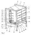
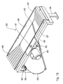
- a separating device 1 for baked goods 2 is shown in FIGS. 1 to 7 shown.
- Baked goods 2 are e.g. to partially frozen partially baked Bun.
- deep-frozen partially baked may not frozen partially baked, frozen non-baked or partially frozen Unbaked pieces of baked goods 2 are processed.
- the separating device 1 has a total of sixteen storage compartments as baked goods storage containers 3 on.
- Each of the storage compartments 3 has an oblique from an outer Addition section 4 obliquely towards an inner transfer section 5 sloping shelf 6.
- the shelves 6 of the storage compartments 3 are roller conveyors executed.
- Four of the sixteen storage compartments 3 are on each floor arranged one above the other.
- the storage compartments 3 are one Carrying frame 7 of a mobile transport carriage 8 worn. The latter points four support feet 9, each with a roller 10.
- For transportation through an operator has the trolley 8 on a handle 11.
- the transfer sections 5 of eight each of the sixteen storage compartments 3 are towards two opposite end faces of the transport carriage 8 open.
- Storage compartments 3 are arranged as 2x4 storage compartments next to each other 3, that is to say in two groups of four arranged next to one another.
- the adjacent storage compartments 3 have shelves 6 and through a vertical, continuous middle partition 12 separated from each other.
- the storage area of the separating device 1 is arranged symmetrically to the partition 12.
- the transfer sections 5 of the storage compartments 3 are by means of transfer flaps 13 closable, each via a horizontal Swivel joint 14 between a closed position, in which the Close transfer section 5, and an open position in which one Transfer from the respective storage compartment 3 is possible, pivotable are. With the help of a spring, the transfer flaps 13 are in the closed position biased.
- Fig. 2 shows the transfer flap 13 of the bottom right Storage compartment 3 in the open position and the other transfer hatches 13 in the closed position.
- An actuating lever is rotatably fixed to each of the transfer flaps 13 15 in the extension of the swivel joints 14 of each transfer flap 13 assigned.
- the total of sixteen operating levers 15 are through opposite side walls 16, 17 of the trolley 8, which run parallel to the partition 12, passed through, so that an actuation the operating lever 15 separated by the side walls 16, 17 from the storage compartments 3.
- the operating levers are in a closed position 15 biased by springs 18 from the respective side wall 16, 17 are held. Due to the arrangement of the storage compartments 3 are the actuating levers passed through one of the side walls 16, 17 15 in two groups of four arranged one above the other.
- each of the operating lever 15 of one of these groups of four serves a driver 19 so that a side wall for the actuating lever 15 16, 17 two drivers 19 are provided.
- the two of a side wall 16, 17 associated drivers 19 are fixed with an endless drive chain 20 connected, which are arranged one above the other Deflection pinion 21, 22 is guided. The latter are assigned by the Side wall 16, 17 worn.
- the respective lower deflection pinion 22 is via a further endless drive chain 23 and a drive sprocket 24 Drive motor 25 driven.
- the operating lever 15 of the the lower left storage compartment 3 facing the viewer in an open position and the other operating levers 15 are in the closed position shown.
- the transfer sections 5 of the storage compartments 3 is in the separating device 1 a separation unit 26 for separation and promotion the baked goods 2 downstream to a delivery section 27.
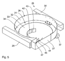
- the Separating unit 26 is shown in greater detail in FIGS. 3 to 7. It comprises an essentially round delivery container 28 which is made of two opposite, U-shaped profiled support profiles 29, 30 worn which, in turn, is fixed on the support feet 9 of the transport carriage 8 are.
- the conveying container 28 has a round container bottom 31 and an essentially cylindrical container wall 32.
- the container bottom 31 is in a round inner portion 33 and an annular surrounding this Outer section 34 divided.
- the inner portion 33 and the outer portion 34 are independent of each other in the manner of a turntable can be driven about a common central axis of rotation 35, which is perpendicular stands on the bottom level of the container bottom 31.
- the inner portion 33 is by means of a drive motor 36 rotatable about the axis of rotation 35, the below the container base 31 on the support frame 7 of the transport carriage 8 is set.
- A also serves to rotate the outer section 34 the container bottom 31 arranged drive motor 37, which is also on Support frame 7 is set.
- the drive motor 37 drives a drive pinion 38, which is via a drive chain, not shown Transmission pinion 39 drives.
- the transmission pinion 39 is about the axis of rotation 35, supported by an axial-radial bearing 40, which also is fixed to the support frame 7, rotatable.
- the transmission pinion is via bracket 41 39 rotatably connected to the outer portion 34.
- baffle 42 Rigidly connected to the container wall 32 is a baffle 42, which is one first curved guide section 43 and a second, in comparison for this purpose has a short straight guide section 44. Both guide sections 43, 44 run just above the container bottom 31 that they on this can arrange arranged baked goods 2.
- the longer guide section 43 runs as particularly the supervision of FIG. 6 shows, starting from the Container wall 32 in an increasingly more clockwise curve Arch to an area above the center of the inner section 33.
- the short guide section 44 essentially covers the entire Width of the outer section 34. In the area of the short guide section 44, the otherwise closed container wall 32 is interrupted the discharge section 27 of the separating unit 26 adjoins this.
- the dispensing section 27 sets the container bottom 31 outside the outer section 34 a little further before there is a delivery opening 45 connects.
- a sensor element 46 projects into the discharge opening 45 a sensor 47 for counting the amount passing through the discharge opening 45 Backguts 2.
- sensor 47 e.g. a light barrier must be used.
- the separating device 1 with the separating unit 26 becomes as follows used: First, the storage compartments 3 of the trolley 8 filled, for this purpose all transfer flaps 13 in the closed position available. The trolley 8 is then in position brought that the discharge opening 45 above a not shown Processing device for the baked goods 2, e.g. a baking device or a packaging device for baked goods containers comes.
- Processing device for the baked goods 2 e.g. a baking device or a packaging device for baked goods containers comes.
- baked goods 2 from the storage compartments 3 are made as required Separation unit 26 supplied.
- the drive motors 25 controlled by a Central control device, not shown, the drive motors 25 so controlled that the drivers 19 sequentially the actuating lever 15th shift from the closed position to the open position so that the assigned Open the transfer flaps 13 in the respective storage compartments 3 intermediate baked goods 2 from the respective transfer section 5 is transferred to the conveying container 28 of the separating unit 26.
- the actuated drive motor 25 stops as soon as the transfer door 13 is fully open.
- the baked goods 2 initially predominantly stand out the inner section 33 of the container bottom 31 of the conveying container 28.
- the inner section 33 controlled by the drive motor 36, is first briefly, e.g. for five seconds, counterclockwise the supervision of Fig. 6 rotated.
- the guide section 43 of the guide plate 42 becomes a guide plate due to the relative movement of the inner section 33 42 the baked goods 2 in this way from the inner portion 33 to the Outer section 34 transported.
- the outer section rotates 34, driven by the drive motor 37, clockwise in Fig. 6, so that the baked goods 2 lying on the outer section 34 toward the delivery section 27 is promoted where it goes from the outer section 34 through the short Guide section 44 of the guide plate 42 is guided.
- the direction of rotation of the inner section 33 is changed from time to time.
- the baked goods 2 fall from the discharge section 27 through the discharge opening 45 and is counted by sensor 47.
- the sensor 47 which is connected to the central control device, this gives one Feedback on the extent to which the requested demand for baked goods 2 is covered.
- the central control device stops the drive motors 36 and 37 and also a further actuation of the drive motors 25, so that no further transfer flap 13 is opened. That through the Dispensing opening 45 falling baked goods 2 then reach the corresponding one Further processing, e.g. baked or packaged.
- FIGS 1 Another variant of a separating device is shown in FIGS 1 as part of a baking system 48.
- a storage device 49 for baked goods 2 comprises in the baking system 48 two mobile container carriers 50 arranged next to one another, of which one is shown in the section of FIG. 9. On the closer structure of the container carrier 50 does not matter below.
- Storage compartments 51 are in there arranged similarly to the storage compartments 3 according to the design Figures 1 to 7. From there, the baked goods 2 passes through a central Fall chute 52 into an intermediate container 53 of a separating device 54 of the baking system 48.
- the intermediate container 53 is below the Drop shaft 52 arranged.
- the separating device 54 has accordingly the separating device 1 of the embodiment according to FIGS. 1 to 7 also the function of conveying the baked goods 2 from the intermediate container 53, which represents an addition section of the separating device 54, towards a delivery section 55, with a baked goods separation takes place.
- the separating device 54 is shown in isolation in FIG. 11 and the intermediate container 53 individually in FIGS. 14 and 15.
- the intermediate container 53 which is open at the top, is laterally delimited by two opposite side walls 56, 57, which on a support frame 58th are mounted. Furthermore, the intermediate container 53 is between the side walls 56, 57 laterally bounded by an intermediate container bottom 59 opposite, falling roller conveyors 60.
- the intermediate container bottom 59 is approximately semicircular and about a vertical axis 61, which runs through the center of this semicircle, pivotable. The pivot axis 61 is therefore in relation to the surface of the intermediate container bottom 59 off-center.
- a drive pinion 62 on the support frame 58 engages with the swivel drive fixed drive motor 63 in a complementary to this Counter body in the intermediate container bottom 59.
- the current position of the intermediate container bottom 59 that is its current swivel position about the pivot axis 61 is detected by sensors 64, 65.
- the angular position sensor 64 detects the current swivel angle of the Intermediate container bottom 59 around the pivot axis 61.
- the one as a light barrier executed sensor 65 detects whether the intermediate container bottom 59th in a e.g. 10 in the closed position, in which he Intermediate container 53 closes completely, or in one opposite the Closed position about the axis 61 pivoted delivery position is present. In the closed position, the light barrier of sensor 65 is activated by the Intermediate container bottom 59 not interrupted, in the delivery positions however, yes.
- Two delivery positions of the intermediate container bottom 59 are exemplary shown in Figures 14 and 15.
- 14 is in the delivery position the intermediate container bottom 59 completely 180 ° from the closed position pivoted out so that the intermediate container 53 is open at the bottom.
- the intermediate container bottom is 59 ⁇ m about 60 ° counterclockwise around the pivot axis 61 from the Pivoted out closed position so that a discharge opening 66 results, the width of which is approximately a quarter of the fully opened delivery opening 66 according to FIG. 14.
- a separating unit 67 of the separating device 54 arranged, e.g. shown in Fig. 11.
- the intermediate container 53 and the conveying container 68 are carried by support profiles 69, which in turn fixed on a support frame 70 of the baking system 48 are.
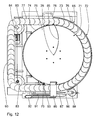
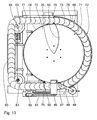
- the conveying container 68 has a substantially round container bottom 71 and a substantially cylindrical container wall 72 with a first Container wall section 73, which is shown on the right in FIG. 12, and a second, in Fig. 12 left container wall section 74, which compared to first container wall section 73 has a smaller radius of curvature.
- the container bottom 71 has a round inner section 75 Type of inner portion 33 of the embodiment according to FIGS. 1 to 7 and one this partially ring-shaped outer section 76, which partially surrounds the outside on.
- the latter is formed by a scale band Conveyor belt 77, which in the top view according to FIG. 12 clockwise circulates.
- the conveyor belt 77 enters the conveyor container 68 in FIG.
- the conveyor belt scale 77 is supported by a conveyor chain 80.
- the latter is in the area of Outer section 76 guided in a part-circular guide profile 81 (see Fig. 9).
- the section of the conveyor belt 77 outside the Conveyor 68, ie between the outlet opening 79 and the Entry opening 78 is guided by further guide profiles 82 and deflected by two pinions 83 engaging in the conveyor chain 80, wherein one of the pinions 83 is driven by a motor 84.
- the inner portion 75 is about the central vertical through the drive motor 36 Rotation axis 35 rotatable, as in connection with the design 1 to 7 described.
- the downstream Separation deflector 86 a separation sensor designed as a light barrier 89 assigned.
- the conveyor belt is in the region of the outlet opening 79 77 inwards through a deflection roller 90 and outwards through a boundary wall section running parallel to the conveyor belt 77 91 limited. Downstream of the boundary wall section 91 is adjacent a further light barrier sensor 92 is arranged on the conveyor belt 77.
- a straight section of the conveyor belt between the two Deflection pinions 83 provides an output conveyor strand 93 of the conveyor belt 77, that is, a delivery section of this.
- an output slide is adjustable 94 (see Fig. 10). This is guided over a guide rail 95, which is connected to the support frame 70 of the baking system 48.
- the delivery slide 94 support channels 96 downstream, which are connected to an endless conveyor belt 97. The latter runs around horizontally arranged deflection shafts 98, of which one is powered.
- a loading opening 99 Under the upper reversal point of the endless conveyor belt 97 in the Baking system 48 is a loading opening 99, under which in turn Oven 100 is arranged.
- Oven 100 In Fig. 9 on the left below a baking drum 101 of the baking oven 100, a dispensing chute 102 is arranged which points towards an output opening 103 drops to a removal container 104 for baked baked goods 2 leads.
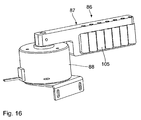
- the deflector flap 87 is in sections as a roller conveyor with a plurality of side by side arranged and rotatable about a vertical axis of rotation rollers 105 trained.
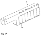
- FIG. 17 shows the discharge slide 94 in an enlarged view.
- the sliding section of this is, comparable to the deflector flap 87, formed as a roller conveyor with a plurality of rollers 106, which are side by side arranged and rotatable about a vertical axis of rotation.
- the storage compartments 51 of the two container carriers 50 are filled.
- the Container carrier 50 arranged quite away from the rest of the baking system 48 his.
- the container carriers 50 are next to each other placed in a position corresponding to that in Fig. 9. controlled about 60 pieces of baked goods 2 fall through from the storage compartments 51 the chute 52 into the intermediate container 53.
- the intermediate container base When the intermediate container 53 is filled, the intermediate container base is located 59 in the closed position shown in FIG. 10. After that Filling the intermediate container 53 becomes the intermediate container bottom 59 in a first delivery position according to FIG. 15. Part of the in the intermediate container 53 baked goods 2 then fall from the intermediate container 53 in the delivery container 68.
- the delivery position is selected so that do not get more than 25 pieces of baked goods into the conveying container 68 at a time.
- the separating unit 67 finds the Separation device 54 a separation of the baked goods 2 instead. For this the inner section 75 of the container bottom 71 rotates counterclockwise, so that the baked goods 2, deflected from the baffle 85 within of the conveyor container 68 in the region of the inlet opening 78 of the conveyor belt 77 arrives.
- the level of the conveyor belt 77 in the area of the inlet opening 78 be slightly lower than that of the inner section 75.
- the exit opening 79 can in turn be the level of the conveyor belt 77 may be slightly higher than that of the inner section 75 Entry opening 78 to avoid jamming of the baked goods 2, the rotates Inner section 75 again and again briefly clockwise. Usually the inner portion 75 rotates counterclockwise.
- the output slide 94 is in the farthest downstream position of the conveyor belt 77.
- the leading piece of baked goods 2 is then from the output slide 94 below Influence of the entraining movement by the conveyor belt 77 and below Gravitational influence transferred to the support channel 96.
- This issue through the output slide 94 rolls the individual piece of baked goods 2 to the Rolls 106 of the discharge pusher 94. This will make the piece of baked goods 2 spared and prevents it from sticking to the discharge slide 94.
- the support channel 96 is in the loading position during the transfer near the bottom reversal point of the conveyor belt 97.
- the endless conveyor belt 97 moved a little further until the next support channel 96 the output conveyor strand 93 is adjacent. Then this next one Tray 96 filled according to the above. This process repeats itself until all support channels 96 each with a set of pieces Baked goods 2 are loaded.
- the endless conveyor belt 97 is then shown in FIG. 9 Moves counterclockwise until the first, leading with baked goods equipped support channel 96 a position in the area of the upper turning point for the endless conveyor belt has reached 97. When moving the Endless conveyor belt 97 falls that associated with this leading support channel 96 Set of pieces of baked goods 2 through the opened loading opening 99 in the oven 100.
- the inner baking drum 101 and the endless conveyor belt 97 are then moved synchronously so that the oven 100 is filled with sets of pieces of baked goods 2. Subsequently the baked goods 2 are baked in the oven 100.
- the endless conveyor belt 97 can be reset so that the first support channel 96 is again adjacent to the discharge conveyor run 93, so that already during the baking a new separation sequence, like described above can take place.
- the baked goods 2 fall out of the oven 100 through the discharge opening 103 into the removal container 104 and stands there ready for removal.
- the timing and the position specification for the individual Components of the separating device 54 in particular the choice the time for the posting of a specific delivery position of the Intermediate container bottom 59, the choice of the respective delivery position, the Selection of the reversal times for the rotary movement of the inner section 75, the control and monitoring of sensors 89, 92, the separating deflector 86 and the output slide 94 are not one central control device shown controlled. The latter works accordingly what above in connection with the separating device was explained according to Figures 1 to 7.
Landscapes
- Life Sciences & Earth Sciences (AREA)
- Engineering & Computer Science (AREA)
- Food Science & Technology (AREA)
- Manufacturing And Processing Devices For Dough (AREA)
- Specific Conveyance Elements (AREA)
Abstract
Description
- Fig. 1
- eine perspektivische Ansicht einer Vereinzelungsvorrichtung für Backwaren;
- Fig. 2
- einen vertikalen Schnitt durch die Vereinzelungsvorrichtung nach Fig. 1 parallel zu einer senkrecht zu Fachböden von Vorratsbehältem verlaufenden Mittelebene der Vereinzelungsvorrichtung;
- Fig. 3
- eine perspektivische Ansicht einer Vereinzelungseinheit der Vereinzelungsvorrichtung nach den Fig. 1 und 2;
- Fig. 4
- einen vertikalen Schnitt durch die Vereinzelungseinheit nach Fig. 3 senkrecht zur Schnittebene der Fig. 2;
- Fig. 5
- eine weitere perspektivische Ansicht der Vereinzelungseinheit nach den Fig. 3 und 4;
- Fig. 6
- eine Aufsicht auf die Vereinzelungseinheit nach den Fig. 3 bis 5;
- Fig. 7
- eine Unteransicht der Vereinzelungseinheit nach den Fig. 3 bis 6;
- Fig. 8
- eine perspektivische Ansicht einer Backanlage mit einem Backofen und einer alternativen Vereinzelungsvorrichtung für Backwaren;
- Fig. 9
- einen vertikalen Längsschnitt durch die Backanlage nach Fig. 8;
- Fig.10
- einen perspektivischen Teilausschnitt der Backanlage nach den Figuren 8 und 9 im Bereich der Vereinzelungsvorrichtung;
- Fig. 11
- eine weitere perspektivische Ansicht der Vereinzelungsvorrichtung nach Fig. 10;
- Fig. 12
- eine Aufsicht auf eine Vereinzelungseinheit der Vereinzelungsvorrichtung nach Fig. 11, wobei ein Zugabeabschnitt weggelassen und ein Vereinzelungs-Abweiser in einer Durchgangsstellung dargestellt ist;
- Fig.13
- eine zu Fig. 12 ähnliche Darstellung der Vereinzelungseinheit mit dem Vereinzelungs-Abweiser in Abweisestellung;
- Fig. 14 u. 15
- perspektivisch den Zugabeabschnitt der Vereinzelungsvorrichtung nach Fig. 11 in zwei verschiedenen Abgabestellungen eines Zwischenbodens;
- Fig. 16
- vergrößert einen Vereinzelungs-Abweiser der Vereinzelungsvorrichtung nach Fig. 11; und
- Fig.17
- vergrößert einen Ausgabeschieber der Vereinzelungsvorrichtung nach Fig. 11.
Claims (13)
- Vereinzelungsvorrichtung (1; 54) für Backgut (2)dadurch gekennzeichnet, dass die Vereinzelungseinheit (26; 67) umfasst:mit einem Zugabeabschnitt (4; 53) zum Zuführen einer Mehrzahl von Stücken Backgut (2),mit einer Vereinzelungseinheit (26; 67) zum Vereinzeln der zugeführten Stücke Backgut (2),mit einem Abgabeabschnitt (27; 93) zum einzelnen Abgeben der vereinzelten Stücke Backgut (2),einen Behälter (28; 68) mit einem Behälterboden (31; 71), der unterteilt ist in einen runden Innenabschnitt (33; 75), dem das Backgut (2) zugeführt wird, und in einen diesen zumindest teilweise umgebenden, insbesondere ringförmigen Außenabschnitt (34; 76),wobei der Außenabschnitt (34; 76) relativ zum Innenabschnitt (33; 75) um eine senkrecht auf der Behälterbodenebene stehende Rotationsachse (35) drehantreibbar ist und mit dem Abgabeabschnitt (27; 93) in Förderverbindung steht.
- Vereinzelungsvorrichtung nach Anspruch 1, dadurch gekennzeichnet, dass der Innenabschnitt (33; 75) unabhängig vom Außenabschnitt (34; 76) um die Rotationsachse (35) drehantreibbar ist.
- Vereinzelungsvorrichtung nach Anspruch 1 oder 2, dadurch gekennzeichnet, dass der Behälter (28; 68) ein starres Leitblech (42; 85) aufweist, welches derart geformt ist, dass aufgrund einer Relativbewegung zwischen dem Leitblech (42; 85) und dem Innenabschnitt (33; 75) Backgut (2), welches zunächst auf dem Innenabschnitt (33; 75) liegt, zum Außenabschnitt (34; 76) abgelenkt wird.
- Vereinzelungsvorrichtung nach einem der Ansprüche 1 bis 3, dadurch gekennzeichnet, dass der Innenabschnitt (33; 75) um die Rotationsachse (35) mit wechselndem Drehsinn antreibbar ist.
- Vereinzelungsvorrichtung nach einem der Ansprüche 1 bis 4, gekennzeichnet durch einen Sensor (47; 89, 92), insbesondere eine Lichtschranke, zum Zählen der vereinzelten Stücke Backgut (2).
- Vereinzelungsvorrichtung nach einem der Ansprüche 1 bis 5, dadurch gekennzeichnet, dass der Zugabeabschnitt (53) durch einen Zwischenbehälter gebildet ist, der derart ausgestaltet ist, dass aus diesem eine Teilmenge von Stücken Backgut (2) an die nachgelagerten Komponenten der Vereinzelungsvorrichtung abgegeben wird.
- Vereinzelungsvorrichtung nach Anspruch 6, dadurch gekennzeichnet, dass der Zwischenbehälter (53) eine in ihrer Weite einstellbare Abgabeöffnung (66) aufweist.
- Vereinzelungsvorrichtung nach Anspruch 7, dadurch gekennzeichnet, dass der Zwischenbehälter (53) einen um eine außermittige Achse (61) zwischen wenigstens einer Offen- und Schließstellung verstellbaren und in der jeweiligen Stellposition die Weite der Abgabeöffnung (66) vorgebenden Zwischenbehälterboden (59) aufweist.
- Vereinzelungsvorrichtung nach einem der Ansprüche 1 bis 8, dadurch gekennzeichnet, dass die Vereinzelungseinheit (26; 67) einen als Förderband (77), insbesondere als Schuppenband, ausgeführten Außenabschnitt (76) aufweist.
- Vereinzelungsvorrichtung nach einem der Ansprüche 1 bis 9, gekennzeichnet durch einen Vereinzelungs-Abweiser (86), der mit mindestens einem Vereinzelungssensor (89) zusammenarbeitet und abhängig von einem Signal des Vereinzelungssensors (89) die einem ersten, auf dem Außenabschnitt (76) geförderten Stücke Backgut (2) folgenden Stücke Backgut (2) vom Außenabschnitt (76) zurück auf den Innenabschnitt (75) befördert.
- Vereinzelungsvorrichtung nach Anspruch 10, gekennzeichnet durch einen dem Vereinzelungs-Abweiser (86) in Förderrichtung des Außenabschnitts (76) nachgelagerten weiteren Sensor (92) zur Erfassung von auf dem Außenabschnitt (76) und/oder dem Abgabeabschnitt nach dem Vereinzelungs-Abweiser (86) geförderten Stücken Backgut (2).
- Vereinzelungsvorrichtung nach Anspruch 10 oder 11, dadurch gekennzeichnet, dass der Abgabeabschnitt (93) einen Ausgabeschieber (94) aufweist, der einem Ausgabe-Fördertrum (93) des Außenabschnitts (76) nach dem Vereinzelungs-Abweiser (86) zugeordnet ist und Backgut (2) quer zur Förderrichtung des Ausgabe-Fördertrums (93) von diesem abgibt.
- Vereinzelungsvorrichtung nach einem der Ansprüche 1 bis 12, gekennzeichnet durch mindestens ein Ablenkelement (90, 91), insbesondere mit einer um eine vertikale Achse drehbaren Rolle, zur Ablenkung von Backgut hin zum Außenabschnitt (76) und/oder von diesem weg.
Applications Claiming Priority (6)
| Application Number | Priority Date | Filing Date | Title |
|---|---|---|---|
| DE10326481 | 2003-06-10 | ||
| DE10326481 | 2003-06-10 | ||
| DE10336457 | 2003-08-06 | ||
| DE10336457 | 2003-08-06 | ||
| DE10358540 | 2003-12-15 | ||
| DE10358540A DE10358540A1 (de) | 2003-06-10 | 2003-12-15 | Vereinzelungsvorrichtung für Backgut |
Publications (3)
| Publication Number | Publication Date |
|---|---|
| EP1486120A2 true EP1486120A2 (de) | 2004-12-15 |
| EP1486120A3 EP1486120A3 (de) | 2005-12-07 |
| EP1486120B1 EP1486120B1 (de) | 2009-04-29 |
Family
ID=33303433
Family Applications (1)
| Application Number | Title | Priority Date | Filing Date |
|---|---|---|---|
| EP04013093A Expired - Lifetime EP1486120B1 (de) | 2003-06-10 | 2004-06-03 | Vereinzelungsvorrichtung für Backgut |
Country Status (2)
| Country | Link |
|---|---|
| US (1) | US6997105B2 (de) |
| EP (1) | EP1486120B1 (de) |
Cited By (2)
| Publication number | Priority date | Publication date | Assignee | Title |
|---|---|---|---|---|
| DE102004041276A1 (de) * | 2004-08-25 | 2006-03-02 | Kamps Brot- Und Backwaren Gmbh | Ausgabeeinheit für Backwaren |
| EP1591011A3 (de) * | 2004-04-27 | 2007-08-22 | Werner & Pfleiderer Lebensmitteltechnik GmbH | Backofen |
Families Citing this family (4)
| Publication number | Priority date | Publication date | Assignee | Title |
|---|---|---|---|---|
| CN102749430B (zh) * | 2012-07-24 | 2014-09-24 | 力合科技(湖南)股份有限公司 | 一种废水监测设备、系统及方法 |
| ES1260666Y1 (es) * | 2020-11-23 | 2021-12-28 | Posimat Sa | Maquina para orientar y alinear articulos alimentados a granel |
| CN115072344B (zh) * | 2022-07-01 | 2024-05-17 | 新昌沛斯轴承配件有限公司 | 一种轴承内圈的传输装置 |
| CN115644202B (zh) * | 2022-12-07 | 2023-09-29 | 沂水浩客食品有限公司 | 双通道面点自动理胚装置 |
Family Cites Families (24)
| Publication number | Priority date | Publication date | Assignee | Title |
|---|---|---|---|---|
| DE1004539B (de) * | 1953-10-28 | 1957-03-14 | Sig Schweiz Industrieges | Verfahren und Vorrichtung zum Ausrichten und Hintereinanderreihen von Gegenstaenden |
| DE1274502B (de) * | 1963-05-03 | 1968-08-01 | Ael Food Machinery Division In | Verfahren und Vorrichtung zum Ausrichten von nicht rotationssymmetrischen Pralinen oder aehnlich gestalteten Suesswaren |
| US4205743A (en) * | 1978-05-26 | 1980-06-03 | Whitmore Henry B | Conveyor feeder for candy eggs |
| US4508025A (en) * | 1983-06-16 | 1985-04-02 | Schultz George A | Tortilla press and oven unit |
| US4528900A (en) * | 1983-10-11 | 1985-07-16 | Nabisco Brands, Inc. | High production apparatus for forming filled edible products |
| US4668524A (en) * | 1986-01-29 | 1987-05-26 | Lawrence Equipment Inc. | Dough ball conveyor loader apparatus and method |
| IT1220297B (it) * | 1988-02-25 | 1990-06-15 | Gd Spa | Dispositivo selezionatore di caramelle |
| US4936203A (en) * | 1988-09-03 | 1990-06-26 | Rheon Automatic Machinery Co., Ltd. | Apparatus for shaping and arraying spheroidal bodies of food materials |
| AT392195B (de) * | 1988-12-20 | 1991-02-11 | Koenig Helmut | Vorrichtung zum wirken von portionierten teigstuecken |
| US5060562A (en) * | 1990-10-05 | 1991-10-29 | Augusto Florindez | Rotary indexing machine |
| DE59204441D1 (de) * | 1991-07-12 | 1996-01-04 | Koenig Elisabeth | Vorrichtung zum wirken portionierter teigstücke. |
| AT397024B (de) * | 1991-07-12 | 1994-01-25 | Koenig Helmut | Vorrichtung zum behandeln von teig |
| DE4141830C2 (de) | 1991-12-18 | 1996-02-29 | Philipp Waldinger | Stapel- und Verpackungsvorrichtung für Einzelstücke |
| DE9202111U1 (de) * | 1992-02-19 | 1992-11-05 | Seiser, Helmut, 79697 Wies | Selbtbedienung von Broten und Brötchen durch entsprechende technische Vorrichtungen und unter Einhaltung der Bäckerei Hygiene Verordnung, B-W, 14.06.77 |
| US5375509A (en) * | 1992-02-20 | 1994-12-27 | The Clorox Company | Dough ball preparation table |
| EP0806382B1 (de) * | 1996-05-06 | 2002-02-13 | AZIONARIA COSTRUZIONI MACCHINE AUTOMATICHE-A.C.M.A.-S.p.A. | Vorrichtung zum Ausrichten eines Produktes, insbesondere von Produkten die einer Herstellungsmaschine zugeführt werden |
| US5996476A (en) * | 1996-07-09 | 1999-12-07 | Schultz; George A. | Device for pressing, imprinting and cooking flat bread products |
| DE19633448B4 (de) | 1996-08-20 | 2004-01-29 | Johann Kasper Bäckereimaschinenbau GmbH | Bäckereimaschine, insbesondere Teigwickelmaschine |
| DE19653090C1 (de) * | 1996-12-20 | 1998-06-25 | Hugo Schindel | Vorrichtung zum Vereinzeln und Transportieren von Flaschen und Formteilen |
| US5954185A (en) * | 1997-08-06 | 1999-09-21 | Sims Machine & Controls, Inc. | Centrifugal feeder |
| US5932264A (en) * | 1997-10-07 | 1999-08-03 | General Mills, Inc. | Method for preparing cooked cereal dough using twin screw preconditioning extruder |
| US6065392A (en) * | 1998-09-18 | 2000-05-23 | Florindez; Augusto | Apparatus for manufacturing different shaped bakery products |
| DE10116423C2 (de) * | 2001-04-02 | 2003-07-03 | Wima Maschb Diersen Gmbh | Transportable Vorrichtung zum Aufbacken von Backprodukten, insbesondere länglichen Backprodukten (Baguettes) |
| DE10245464A1 (de) * | 2002-09-28 | 2004-04-08 | Werner & Pfleiderer Lebensmitteltechnik Gmbh | Backofen |
-
2004
- 2004-06-03 EP EP04013093A patent/EP1486120B1/de not_active Expired - Lifetime
- 2004-06-10 US US10/864,864 patent/US6997105B2/en not_active Expired - Fee Related
Cited By (3)
| Publication number | Priority date | Publication date | Assignee | Title |
|---|---|---|---|---|
| EP1591011A3 (de) * | 2004-04-27 | 2007-08-22 | Werner & Pfleiderer Lebensmitteltechnik GmbH | Backofen |
| DE102004041276A1 (de) * | 2004-08-25 | 2006-03-02 | Kamps Brot- Und Backwaren Gmbh | Ausgabeeinheit für Backwaren |
| DE102004041276B4 (de) * | 2004-08-25 | 2006-08-03 | Kamps Brot- Und Backwaren Gmbh | Ausgabeeinheit für Backwaren |
Also Published As
| Publication number | Publication date |
|---|---|
| EP1486120A3 (de) | 2005-12-07 |
| US6997105B2 (en) | 2006-02-14 |
| US20050022677A1 (en) | 2005-02-03 |
| EP1486120B1 (de) | 2009-04-29 |
Similar Documents
| Publication | Publication Date | Title |
|---|---|---|
| EP0960814B1 (de) | Vorrichtung zum Zuführen von Produkten zu einer Verpackungsmaschine | |
| DE3916671C2 (de) | Verfahren und Vorrichtung zum aufeinanderfolgenden Fördern von flachen Süßigkeiten | |
| EP0453407B1 (de) | Verfahren und Vorrichtung zur Bildung von Gruppen von Nahrungsmittelscheiben | |
| EP2799348B1 (de) | Verfahren zur Gruppierung von Artikeln zu Artikelstangen und Gruppiereinrichtung sowie Verpackungsmaschine mit einer solchen | |
| EP3153025B1 (de) | Vorrichtung zum behandeln einzelner würste | |
| EP0312490B1 (de) | Verfahren und Vorrichtung zur Bildung und zum Transport von Gruppen flachseitig aneinander liegender Nahrungsmittelscheiben, insbesondere Biscuits | |
| EP2763918B1 (de) | Verfahren und vorrichtung zum fördern von streifenförmigen oder plattenförmigen produkten | |
| DE1461792A1 (de) | Eierverpackungsmaschine | |
| EP1216939A1 (de) | Vorrichtung zum Fördern und Zwischenspeichern von Produkten | |
| DE69411473T2 (de) | Kombinatorische Messsysteme und -verfahren | |
| DE602005000656T2 (de) | Einheit für die Übergabe von Produkten von einer Verpackungsmaschine zur Verschachtelung | |
| EP1486121A2 (de) | Beschickungsvorrichtung für einen Backofen sowie Backanlage mit einer derartigen Beschickungsvorrichtung und einem Backofen | |
| EP1591011B1 (de) | Backofen | |
| EP3680032A1 (de) | Sortierer | |
| DE10358540A1 (de) | Vereinzelungsvorrichtung für Backgut | |
| EP1486120B1 (de) | Vereinzelungsvorrichtung für Backgut | |
| EP1586520B2 (de) | Zwischenspeicher | |
| DE10116423C2 (de) | Transportable Vorrichtung zum Aufbacken von Backprodukten, insbesondere länglichen Backprodukten (Baguettes) | |
| WO2012013532A1 (de) | Kontrollstation, vereinzelungsvorrichtung und verfahren zum vereinzeln von stückgütern | |
| DE2558288A1 (de) | Anlage fuer die herstellung von zigarettenpackungen mit direkter beschickung der zigaretten von der bzw. den herstellungsmaschinen zum trichter fuer die gruppierung und die abgabe von zigaretten an die verpackungslinie der verpackungsmaschine, sowie vorrichtung mit magazin fuer den ausgleich von produktionsschwankungen zwischen diesen maschinen | |
| EP0853756B1 (de) | Kombinationswaage | |
| EP0745535B1 (de) | Beladeeinrichtung | |
| EP1577848B1 (de) | Ausgabeeinheit für Waren, insbesondere Backwaren | |
| CH673627A5 (en) | Storage and distribution machine - directs selectively to sidings with buffer-storage units and reversible conveyor | |
| DE1158444B (de) | Vorrichtung zum Zufuehren von gefuellten Behaeltern in zwei Reihen zu einer Verarbeitungsanlage |
Legal Events
| Date | Code | Title | Description |
|---|---|---|---|
| PUAI | Public reference made under article 153(3) epc to a published international application that has entered the european phase |
Free format text: ORIGINAL CODE: 0009012 |
|
| AK | Designated contracting states |
Kind code of ref document: A2 Designated state(s): AT BE BG CH CY CZ DE DK EE ES FI FR GB GR HU IE IT LI LU MC NL PL PT RO SE SI SK TR |
|
| AX | Request for extension of the european patent |
Extension state: AL HR LT LV MK |
|
| PUAL | Search report despatched |
Free format text: ORIGINAL CODE: 0009013 |
|
| AK | Designated contracting states |
Kind code of ref document: A3 Designated state(s): AT BE BG CH CY CZ DE DK EE ES FI FR GB GR HU IE IT LI LU MC NL PL PT RO SE SI SK TR |
|
| AX | Request for extension of the european patent |
Extension state: AL HR LT LV MK |
|
| RIC1 | Information provided on ipc code assigned before grant |
Ipc: 7A 21C 9/08 B Ipc: 7B 65G 47/14 B Ipc: 7A 21B 3/07 A |
|
| 17P | Request for examination filed |
Effective date: 20060513 |
|
| AKX | Designation fees paid |
Designated state(s): AT BE BG CH CY CZ DE DK EE ES FI FR GB GR HU IE IT LI LU MC NL PL PT RO SE SI SK TR |
|
| 17Q | First examination report despatched |
Effective date: 20060804 |
|
| GRAP | Despatch of communication of intention to grant a patent |
Free format text: ORIGINAL CODE: EPIDOSNIGR1 |
|
| GRAS | Grant fee paid |
Free format text: ORIGINAL CODE: EPIDOSNIGR3 |
|
| GRAA | (expected) grant |
Free format text: ORIGINAL CODE: 0009210 |
|
| AK | Designated contracting states |
Kind code of ref document: B1 Designated state(s): AT BE BG CH CY CZ DE DK EE ES FI FR GB GR HU IE IT LI LU MC NL PL PT RO SE SI SK TR |
|
| REG | Reference to a national code |
Ref country code: GB Ref legal event code: FG4D Free format text: NOT ENGLISH |
|
| REG | Reference to a national code |
Ref country code: CH Ref legal event code: EP |
|
| REF | Corresponds to: |
Ref document number: 502004009408 Country of ref document: DE Date of ref document: 20090610 Kind code of ref document: P |
|
| REG | Reference to a national code |
Ref country code: IE Ref legal event code: FG4D |
|
| PG25 | Lapsed in a contracting state [announced via postgrant information from national office to epo] |
Ref country code: ES Free format text: LAPSE BECAUSE OF FAILURE TO SUBMIT A TRANSLATION OF THE DESCRIPTION OR TO PAY THE FEE WITHIN THE PRESCRIBED TIME-LIMIT Effective date: 20090809 Ref country code: FI Free format text: LAPSE BECAUSE OF FAILURE TO SUBMIT A TRANSLATION OF THE DESCRIPTION OR TO PAY THE FEE WITHIN THE PRESCRIBED TIME-LIMIT Effective date: 20090429 Ref country code: PT Free format text: LAPSE BECAUSE OF FAILURE TO SUBMIT A TRANSLATION OF THE DESCRIPTION OR TO PAY THE FEE WITHIN THE PRESCRIBED TIME-LIMIT Effective date: 20090829 |
|
| PG25 | Lapsed in a contracting state [announced via postgrant information from national office to epo] |
Ref country code: SI Free format text: LAPSE BECAUSE OF FAILURE TO SUBMIT A TRANSLATION OF THE DESCRIPTION OR TO PAY THE FEE WITHIN THE PRESCRIBED TIME-LIMIT Effective date: 20090429 Ref country code: SE Free format text: LAPSE BECAUSE OF FAILURE TO SUBMIT A TRANSLATION OF THE DESCRIPTION OR TO PAY THE FEE WITHIN THE PRESCRIBED TIME-LIMIT Effective date: 20090729 Ref country code: PL Free format text: LAPSE BECAUSE OF FAILURE TO SUBMIT A TRANSLATION OF THE DESCRIPTION OR TO PAY THE FEE WITHIN THE PRESCRIBED TIME-LIMIT Effective date: 20090429 |
|
| REG | Reference to a national code |
Ref country code: IE Ref legal event code: FD4D |
|
| BERE | Be: lapsed |
Owner name: WERNER & PFLEIDERER LEBENSMITTELTECHNIK G.M.B.H. Effective date: 20090630 |
|
| PG25 | Lapsed in a contracting state [announced via postgrant information from national office to epo] |
Ref country code: MC Free format text: LAPSE BECAUSE OF NON-PAYMENT OF DUE FEES Effective date: 20090630 Ref country code: CZ Free format text: LAPSE BECAUSE OF FAILURE TO SUBMIT A TRANSLATION OF THE DESCRIPTION OR TO PAY THE FEE WITHIN THE PRESCRIBED TIME-LIMIT Effective date: 20090429 Ref country code: EE Free format text: LAPSE BECAUSE OF FAILURE TO SUBMIT A TRANSLATION OF THE DESCRIPTION OR TO PAY THE FEE WITHIN THE PRESCRIBED TIME-LIMIT Effective date: 20090429 Ref country code: RO Free format text: LAPSE BECAUSE OF FAILURE TO SUBMIT A TRANSLATION OF THE DESCRIPTION OR TO PAY THE FEE WITHIN THE PRESCRIBED TIME-LIMIT Effective date: 20090429 Ref country code: DK Free format text: LAPSE BECAUSE OF FAILURE TO SUBMIT A TRANSLATION OF THE DESCRIPTION OR TO PAY THE FEE WITHIN THE PRESCRIBED TIME-LIMIT Effective date: 20090429 Ref country code: IE Free format text: LAPSE BECAUSE OF FAILURE TO SUBMIT A TRANSLATION OF THE DESCRIPTION OR TO PAY THE FEE WITHIN THE PRESCRIBED TIME-LIMIT Effective date: 20090429 |
|
| REG | Reference to a national code |
Ref country code: CH Ref legal event code: PL |
|
| PG25 | Lapsed in a contracting state [announced via postgrant information from national office to epo] |
Ref country code: SK Free format text: LAPSE BECAUSE OF FAILURE TO SUBMIT A TRANSLATION OF THE DESCRIPTION OR TO PAY THE FEE WITHIN THE PRESCRIBED TIME-LIMIT Effective date: 20090429 |
|
| NLV4 | Nl: lapsed or anulled due to non-payment of the annual fee |
Effective date: 20100101 |
|
| PLBE | No opposition filed within time limit |
Free format text: ORIGINAL CODE: 0009261 |
|
| STAA | Information on the status of an ep patent application or granted ep patent |
Free format text: STATUS: NO OPPOSITION FILED WITHIN TIME LIMIT |
|
| GBPC | Gb: european patent ceased through non-payment of renewal fee |
Effective date: 20090729 |
|
| REG | Reference to a national code |
Ref country code: FR Ref legal event code: ST Effective date: 20100226 |
|
| PG25 | Lapsed in a contracting state [announced via postgrant information from national office to epo] |
Ref country code: BG Free format text: LAPSE BECAUSE OF FAILURE TO SUBMIT A TRANSLATION OF THE DESCRIPTION OR TO PAY THE FEE WITHIN THE PRESCRIBED TIME-LIMIT Effective date: 20090729 |
|
| 26N | No opposition filed |
Effective date: 20100201 |
|
| PG25 | Lapsed in a contracting state [announced via postgrant information from national office to epo] |
Ref country code: LI Free format text: LAPSE BECAUSE OF NON-PAYMENT OF DUE FEES Effective date: 20090630 Ref country code: FR Free format text: LAPSE BECAUSE OF NON-PAYMENT OF DUE FEES Effective date: 20090630 Ref country code: CH Free format text: LAPSE BECAUSE OF NON-PAYMENT OF DUE FEES Effective date: 20090630 |
|
| PG25 | Lapsed in a contracting state [announced via postgrant information from national office to epo] |
Ref country code: GB Free format text: LAPSE BECAUSE OF NON-PAYMENT OF DUE FEES Effective date: 20090729 |
|
| PG25 | Lapsed in a contracting state [announced via postgrant information from national office to epo] |
Ref country code: BE Free format text: LAPSE BECAUSE OF NON-PAYMENT OF DUE FEES Effective date: 20090630 Ref country code: DE Free format text: LAPSE BECAUSE OF NON-PAYMENT OF DUE FEES Effective date: 20100101 |
|
| PG25 | Lapsed in a contracting state [announced via postgrant information from national office to epo] |
Ref country code: NL Free format text: LAPSE BECAUSE OF NON-PAYMENT OF DUE FEES Effective date: 20100101 |
|
| PG25 | Lapsed in a contracting state [announced via postgrant information from national office to epo] |
Ref country code: AT Free format text: LAPSE BECAUSE OF NON-PAYMENT OF DUE FEES Effective date: 20090603 |
|
| PG25 | Lapsed in a contracting state [announced via postgrant information from national office to epo] |
Ref country code: GR Free format text: LAPSE BECAUSE OF FAILURE TO SUBMIT A TRANSLATION OF THE DESCRIPTION OR TO PAY THE FEE WITHIN THE PRESCRIBED TIME-LIMIT Effective date: 20090730 |
|
| PG25 | Lapsed in a contracting state [announced via postgrant information from national office to epo] |
Ref country code: IT Free format text: LAPSE BECAUSE OF NON-PAYMENT OF DUE FEES Effective date: 20090603 |
|
| PG25 | Lapsed in a contracting state [announced via postgrant information from national office to epo] |
Ref country code: LU Free format text: LAPSE BECAUSE OF NON-PAYMENT OF DUE FEES Effective date: 20090603 |
|
| PG25 | Lapsed in a contracting state [announced via postgrant information from national office to epo] |
Ref country code: HU Free format text: LAPSE BECAUSE OF FAILURE TO SUBMIT A TRANSLATION OF THE DESCRIPTION OR TO PAY THE FEE WITHIN THE PRESCRIBED TIME-LIMIT Effective date: 20091030 |
|
| PG25 | Lapsed in a contracting state [announced via postgrant information from national office to epo] |
Ref country code: TR Free format text: LAPSE BECAUSE OF FAILURE TO SUBMIT A TRANSLATION OF THE DESCRIPTION OR TO PAY THE FEE WITHIN THE PRESCRIBED TIME-LIMIT Effective date: 20090429 |
|
| PG25 | Lapsed in a contracting state [announced via postgrant information from national office to epo] |
Ref country code: CY Free format text: LAPSE BECAUSE OF FAILURE TO SUBMIT A TRANSLATION OF THE DESCRIPTION OR TO PAY THE FEE WITHIN THE PRESCRIBED TIME-LIMIT Effective date: 20090429 |