EP1485312B1 - System for treating, in particular, cataphoretically immersion painting vehicle bodies - Google Patents
System for treating, in particular, cataphoretically immersion painting vehicle bodies Download PDFInfo
- Publication number
- EP1485312B1 EP1485312B1 EP03708079A EP03708079A EP1485312B1 EP 1485312 B1 EP1485312 B1 EP 1485312B1 EP 03708079 A EP03708079 A EP 03708079A EP 03708079 A EP03708079 A EP 03708079A EP 1485312 B1 EP1485312 B1 EP 1485312B1
- Authority
- EP
- European Patent Office
- Prior art keywords
- trolley
- articles
- dripping
- zone
- vehicle body
- Prior art date
- Legal status (The legal status is an assumption and is not a legal conclusion. Google has not performed a legal analysis and makes no representation as to the accuracy of the status listed.)
- Expired - Fee Related
Links
Images


Classifications
-
- C—CHEMISTRY; METALLURGY
- C25—ELECTROLYTIC OR ELECTROPHORETIC PROCESSES; APPARATUS THEREFOR
- C25D—PROCESSES FOR THE ELECTROLYTIC OR ELECTROPHORETIC PRODUCTION OF COATINGS; ELECTROFORMING; APPARATUS THEREFOR
- C25D13/00—Electrophoretic coating characterised by the process
- C25D13/22—Servicing or operating apparatus or multistep processes
-
- B—PERFORMING OPERATIONS; TRANSPORTING
- B65—CONVEYING; PACKING; STORING; HANDLING THIN OR FILAMENTARY MATERIAL
- B65G—TRANSPORT OR STORAGE DEVICES, e.g. CONVEYORS FOR LOADING OR TIPPING, SHOP CONVEYOR SYSTEMS OR PNEUMATIC TUBE CONVEYORS
- B65G49/00—Conveying systems characterised by their application for specified purposes not otherwise provided for
- B65G49/02—Conveying systems characterised by their application for specified purposes not otherwise provided for for conveying workpieces through baths of liquid
- B65G49/04—Conveying systems characterised by their application for specified purposes not otherwise provided for for conveying workpieces through baths of liquid the workpieces being immersed and withdrawn by movement in a vertical direction
- B65G49/0409—Conveying systems characterised by their application for specified purposes not otherwise provided for for conveying workpieces through baths of liquid the workpieces being immersed and withdrawn by movement in a vertical direction specially adapted for workpieces of definite length
- B65G49/0436—Conveying systems characterised by their application for specified purposes not otherwise provided for for conveying workpieces through baths of liquid the workpieces being immersed and withdrawn by movement in a vertical direction specially adapted for workpieces of definite length arrangements for conveyance from bath to bath
- B65G49/044—Conveying systems characterised by their application for specified purposes not otherwise provided for for conveying workpieces through baths of liquid the workpieces being immersed and withdrawn by movement in a vertical direction specially adapted for workpieces of definite length arrangements for conveyance from bath to bath along a continuous circuit
- B65G49/045—Conveying systems characterised by their application for specified purposes not otherwise provided for for conveying workpieces through baths of liquid the workpieces being immersed and withdrawn by movement in a vertical direction specially adapted for workpieces of definite length arrangements for conveyance from bath to bath along a continuous circuit the circuit being fixed
- B65G49/0454—Conveying systems characterised by their application for specified purposes not otherwise provided for for conveying workpieces through baths of liquid the workpieces being immersed and withdrawn by movement in a vertical direction specially adapted for workpieces of definite length arrangements for conveyance from bath to bath along a continuous circuit the circuit being fixed by means of containers -or workpieces- carriers
- B65G49/0459—Conveying systems characterised by their application for specified purposes not otherwise provided for for conveying workpieces through baths of liquid the workpieces being immersed and withdrawn by movement in a vertical direction specially adapted for workpieces of definite length arrangements for conveyance from bath to bath along a continuous circuit the circuit being fixed by means of containers -or workpieces- carriers movement in a vertical direction is caused by self-contained means
-
- B—PERFORMING OPERATIONS; TRANSPORTING
- B65—CONVEYING; PACKING; STORING; HANDLING THIN OR FILAMENTARY MATERIAL
- B65G—TRANSPORT OR STORAGE DEVICES, e.g. CONVEYORS FOR LOADING OR TIPPING, SHOP CONVEYOR SYSTEMS OR PNEUMATIC TUBE CONVEYORS
- B65G2201/00—Indexing codes relating to handling devices, e.g. conveyors, characterised by the type of product or load being conveyed or handled
- B65G2201/02—Articles
- B65G2201/0294—Vehicle bodies
Description
Die Erfindung betrifft eine Anlage zum Behandeln, insbesondere zum kataphoretischen Tauchlackieren, von Gegenständen, insbesondere von Fahrzeugkarosserien, nach dem Oberbegriff des Patentanspruchs 1.The invention relates to a system for treating, in particular for cataphoretically dipcoating, articles, in particular vehicle bodies, according to the preamble of patent claim 1.
Fahrzeugkarosserien oder andere Gegenstände, die das letzte Spülbad oder die letzte Spritzzone einer kataphoretischen Tauchlackierung verlassen, müssen vor dem Eintritt in den Trockner gut abgetropft werden, wobei gleichzeitig ein Abdunsten stattfindet. Dabei muß vermieden werden, daß sich auf den Gegenständen Tropfnasen, ssgenannte "Läufer", bilden, die nach dem Trocknen im nachgeschalteten Trockner nur noch durch mühsame Schleifarbeiten entfernt werden können. Bei bekannten Anlagen der eingangs genannten Art erfolgt hinter dem letzten Bad der kataphoretischen Tauchlackierzone ein Wechsel der Fördereinrichtung. Beispielsweise werden die mit Hilfe eines Pendelförderers durch die verschiedenen Bäder geführten Fahrzeugkaraosserien, die ihrerseits von Skids getragen sind, in der Abtropfzone auf einen Rollenbahnförderer abgesetzt. Dieser Rollenbahnförderer muß wegen der stark verschmutzenden Wirkung der aus dem Bad verschleppten Flüssigkeit im wesentlichen aus Edelstahl gefertigt werden.Vehicle bodies or other objects leaving the last rinse bath or spray zone of a cataphoretic dip must be well drained prior to entering the dryer, with simultaneous evaporation. It must be avoided that on the objects drip noses, called "runners" form, which can be removed after drying in the downstream dryer only by tedious grinding. In known systems of the type mentioned behind the last bath of the cataphoretic Tauchlackierzone a change of the conveyor. For example, the guided by a shuttle conveyor through the various baths car kare series, which in turn are supported by skids, placed in the drip zone on a roller conveyor. This roller conveyor must be made of stainless steel because of the strong polluting effect of the liquid taken from the bath.
Damit die Flüssigkeit von den Fahrzeugkarosserien und insbesondere aus deren Hohlräumen gut abfließen kann, ist bei den bekannten Lackieranlagen innerhalb der Abtropfzone eine gesonderte Kippvorrichtung vorgesehen. Die Fahrzeugkarosserien müssen von dem Rollenbahn-Förderer auf diese Kippvorrichtung übergeben werden, werden dort in eine gegenüber der Horizontalen verkippte Lage gebracht, sodann wieder in die Horizontale zurückverschwenkt und erneut auf das Rollenbahn-Fördersystem übergeben. Dies ist apparativ sehr aufwendig. Darüber hinaus kann bei einer schnellen Taktzeit der Lackieranlage die jeweils in der Kippvorrichtung befindliche Fahrzeugkaraosserie nur für verhältnißmäßig kurze Zeit aus der Horizontalen zum Abtropfen verschwenkt werden. Der Abtropfvorgang kann daher in vielen Fällen innerhalb der Kippvorrichtung nicht abgeschlossen werden, was dazu führt, daß sich auf den Oberflächen der Fahrzeugkarosserie Tropfnasen ausbilden können.Thus, the liquid from the vehicle bodies and in particular from their cavities can flow well, a separate tilting device is provided in the known paint shops within the drip zone. The vehicle bodies must be transferred from the roller conveyor to this tilting device, are there placed in a tilted relative to the horizontal position, then swung back into the horizontal and handed over again to the roller conveyor system. This is very expensive equipment. In addition, at a fast cycle time of the paint shop located in each case tilting vehicle body can be pivoted only for comparatively short time from the horizontal to drip. The draining process can therefore not be completed within the tilting device in many cases, which leads to the fact that drip noses can form on the surfaces of the vehicle body.
Ein weiterer Nachteil der bekannten Anlage besteht darin, daß mit Hilfe der Kippvorrichtung im allgemeinen nur eine einzige Winkelposition der Fahrzeugkarosserien gegenüber der Horizontalen herbeigeführt werden kann. Es ist jedoch häufig nicht gewährleistet, daß in dieser einzigen Winkelposition die verschleppte Flüsigkeit zuverlässig aus allen Hohlräumen der Fahrzeugkarosserie auslaufen kann.Another disadvantage of the known system is that with the help of the tilting device generally only a single angular position of the vehicle bodies relative to the horizontal can be brought about. However, it is often not guaranteed that in this single angular position the entrained liquid can leak reliably from all voids of the vehicle body.
Anlagen ähnlich derjenigen der eingangs genannten Art sind im Stand der Technik bekannt. Bei der in der
Bei einer aus der
Aufgabe der vorliegenden Erfindung ist es, eine Anlage der eingangs genannten Art so auszugestalten, daß sie mit geringerem apparativen Aufwand auskommt und gleichwohl ein besseres Ergebnis in der Abtropfzone erzielt.Object of the present invention is to provide a system of the type mentioned in such a way that it requires less equipment and still achieves a better result in the drip zone.
Diese Aufgabe wird erfindungsgemäß durch eine Anlage mit den Merkmalen des Patentanspruchs 1 gelöst.This object is achieved by a system with the features of claim 1.
Der Transportwagen, von dem die vorliegende Erfindung Gebrauch macht, ist grundsätzlich aus der
Im Gegensatz zu letzterem kann bei der vorliegenden Erfindung das Abtropfen in gegenüber der Horizontalen verkippter Position auch während der Bewegung des Transportwagens erfolgen. Die Abtropfzeit kann auf diese Weise gegenüber derjenigen in bekannten Anlagen verlängert werden. Werden aufeinanderfolgend unterschiedliche Gegenstände behandelt, kann für jeden Gegenstand die zum Abtropfen geeignete Winkelposition gegenüber der Horizontalen gewählt werden.In contrast to the latter, in the present invention, dripping in a tilted position relative to the horizontal can also take place during the movement of the trolley. The dripping time can be extended in this way over that in known systems. If successively different objects are treated, the angular position suitable for dripping relative to the horizontal can be selected for each object.
Ein weiterer, großer Vorteil der Verwendung derartiger Transportwagen ist darin zu sehen, daß durch eine geeignete Schrägstellung der Fahrzeugkaraosserien bereits über dem letzten Bad ein sehr weitgehendes Abtropfen erreicht werden kann und die Verschleppung von Badflüssigkeit schon aus diesem Grunde gegenüber dem Stande der Technik erheblich verringert ist. Insgesamt kann bei der erfindungsgemäßen Anlage das Abtropfen vor dem Eintritt der Gegenstände in den Trockner optimal abgeschlossen werden, so daß das Auftreten von Tropfnasen, die eine aufwendige Nachbehandlung erforderlich machen würden, weitgehend vermieden werden kann.Another great advantage of using such dolly is the fact that by a suitable inclination of the Fahrzeugkaraosserien already over the last bath a very extensive dripping can be achieved and the carryover of bath liquid is considerably reduced for this reason compared to the prior art , Overall, at the Plant according to the invention, the dripping be completed before the entry of the objects in the dryer optimally, so that the occurrence of drip lugs, which would require a complex treatment required, can be largely avoided.
Besonders bevorzugt wird diejenige Ausführungsform der Erfindung, bei welcher der mindestens eine Transportwagen so steuerbar ist, daß seine Halterung innerhalb der Abtropfzone in mindestens zwei Positionen gebracht wird, in denen sie unterschiedlich gegenüber der Horizontalen verkippt ist. Mit dieser Ausgestaltung wird der Erfahrung Rechnung getragen, daß sich bei kompliziert geformten und Hohlräumen enthaltenden Gegenständen häufig keine (einzige) Winkelposition gegenüber der Horizontalen finden lässt, in der von allen Stellen und aus allen Hohlräumen die Flüssigkeit gut ablaufen bzw. abtropfen kann.Particularly preferred is that embodiment of the invention in which the at least one trolley is controllable so that its holder is placed within the drip zone in at least two positions in which it is tilted differently from the horizontal. With this embodiment, the experience is taken into account that with complicated shaped and cavities containing objects often no (single) angular position relative to the horizontal can be found in the run of all bodies and from all cavities, the liquid well or can drip off.
Ein Ausführungsbeispiel der Erfindung wir nachfolgend anhand der Zeichnung näher erläutert; es zeigen
- Figur 1:
- eine Seitenansicht eines Transportwagens, der in der Lackieranlage verwendet wird, mit einer hieran befestigten Fahrzeugkarosserie in normaler Transportposition;
- Figur 2:
- eine Seitenansicht des Transportwagens ähnlich der
Figur 1 , in welcher die Fahrzeugkarosserie jedoch aus der Transportposition verschwenkt ist; - Figur 3:
- die Draufsicht auf den Transportwagen von
Figur 2 - Figur 4:
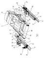
- eine perspektivische Ansicht des Transportwagens samt Fahrzeugkarosserie von
Figur 1 ; - Figur 5:
- einen Schnitt durch
Figur 3 gemäß der dortigen Linie VIII-VIII; - Figuren 6
- und 7: vergrößerte Detailansichten des Transportwagens im Bereich der auf Laufflächen aufstehenden Räder;
- Figur 8:
- schematisch den Übergangsbereich der Lackieranlage zwischen dem letzten Sprüh-/Tauchbehälter und dem KTL-Trockner.
- FIG. 1:
- a side view of a trolley, which is used in the paint shop, with a vehicle body attached thereto in the normal transport position;
- FIG. 2:
- a side view of the trolley similar to the
FIG. 1 in which, however, the vehicle body is pivoted out of the transport position; - FIG. 3:
- the top view of the trolley from
FIG. 2 ; - FIG. 4:
- a perspective view of the trolley including vehicle body of
FIG. 1 ; - FIG. 5:
- a cut through
FIG. 3 according to the local line VIII-VIII; - FIGS. 6
- and Fig. 7: enlarged detail views of the trolley in the area of wheels resting on running surfaces;
- FIG. 8:
- schematically the transition area of the paint shop between the last spray / dip tank and the KTL dryer.
Nachfolgend wird zunächst anhand der
Wie insbesondere die
Die Doppelräder 9, 10 rollen auf einer ersten Lauffläche 13 und die Doppelräder 11, 12 auf einer hierzu parallelen zweiten Lauffläche 14 ab. Die Laufflächen 13, 14 sind ihrerseits auf jeweils einem I-Profilträger 15, 16 montiert, der von einem nicht dargestellten Stahlbau getragen wird.The
In der Mitte der in den
Auf den Transportwagen 5 werden Fahrzeugkarosserien 4 mit Hilfe einer Eintauchvorrichtung getragen, die beidseits der Fahrzeugkarosserien 4 jeweils eine Schwenkvorrichtung umfaßt. Jede dieser Schwenkvorrichtungen besitzt einen Schwenkarm 50, 51, der sich in noch zu beschreibender Weise in einer vertikalen Ebene, die parallel zur Förderrichtung verläuft, verschwenken kann. Hierzu ist jeder Schwenkarm 50, 51 über eine Stummelwelle 52, 53, die senkrecht zur Förderrichtung verläuft, mit der Ausgangswelle eines Getriebes 54, 55 verbunden. Das Getriebe 54, 55 ist an der jeweiligen Längstraverse 7, 8 des Transportwagens 5 etwa in deren mittlerem Bereich befestigt. Es wird von einem Motor 56 bzw. 57 angetrieben, der seitlich an das Getriebe 54, 55 angeflanscht ist.On the
Die in Bewegungsrichtung hinteren Enden der Schwenkarme 50, 51 sind gelenkig mit einer Lasche 58, 59 verbunden, die sich in der normalen, in
Die Winkelstellung, welche die Laschen 58, 59 gegenüber den Schwenkarmen 50, 51 einnehmen, wird jeweils durch eine Verstelleinrichtung bestimmt, die insgesamt das Bezugszeichen 62 bzw. 63 trägt. Jede dieser Verstelleinrichtungen 62, 63 umfaßt ein Gestänge mit zwei parallelen Schubstangen 64, 65 bzw. 66, 67, die an ihren gegenüberliegenden Enden jeweils über eine Verbindungslasche 68, 69 bzw. 70, 71 miteinander verbunden sind. Die in Bewegungsrichtung hinteren Verbindungslaschen 69 bzw. 71 sind an ihrem unteren Ende starr an der Quertraverse 60 festgemacht.The angular position which the
Die in Bewegungsrichtung vorne liegende Verbindungslaschen 70, 71 dagegen sind starr jeweils mit einer Stummelwelle verbunden, die in der Zeichnung nicht erkennbar ist, da sie sich koaxial durch die zugeordnete, als Hohlwelle ausgebildete Stummelwelle 52, 53 hindurcherstreckt.The front in the direction of
Diese weiteren Stummelwellen verlaufen auch durch die Getriebe 54, 55 hindurch und sind an die Ausgangswellen weiterer Getriebe 78, 79 angekoppelt, die seitlich an den Getrieben 54, 55 befestigt sind. Auch an die Getriebe 78, 79 sind Antriebsmotoren 80, 81 angeflanscht.These further stub shafts also pass through the
Die vorderen Enden der beiden Schwenkarme 50, 51 tragen gemeinsam ein Gegengewicht 88, so daß die auf die Stummelwellen 52, 53 wirkenden Drehmomente annähernd bei aufgesetzter Fahrzeugkarosserie 4 ausbalanciert sind.The front ends of the two
Die Doppelräder 19 bis 12 der Transportwagen 5 sind selbst nicht angetrieben. Der Vorwärtstrieb der Transportwagen 5 erfolgt vielmehr über einen gesonderten Antrieb, der nachfolgend anhand der
Parallel zu den beiden Laufflächen 13, 14 erstrecken sich zwei senkrecht ausgerichtete, stationäre Antriebsflansche 26, 27. Diese wirken jeweils mit einem Preßrollenantrieb 28 bzw. 29 zusammen, der an der Seitenfläche der benachbarten Längstraverse 7, 8 mittels einer Lasche 30 bzw. 31 befestigt ist. Die Preßrollenantriebe 28, 29 umfassen jeweils einen elektrischen Antriebsmotor 32, 33 und ein Antriebsgetriebe 34, 35. Letzteres treibt die parallelen, vertikalen Achsen zweier Preßrollen 36, 37 bzw. 38, 39 an, die von beiden Seiten her gegen den jeweils zugeordneten Antriebsflansch 26 bzw. 27 angepreßt werden. Werden die Antriebsmotoren 32, 33 bestromt, laufen die Preßrollen 36, 37 bzw. 38, 39 auf den jeweiligen Seitenflächen der Antriebsflansche 26, 27 ab und bewegen dabei den Transportwagen 5 auf den Laufflächen 13, 14 vorwärts.Parallel to the two running
Jeder Transportwagen 5 umfaßt seine eigene Wagensteuerung, unter deren Regime er sowohl seine Translationsbewegung entlang der Laufflächen 13, 14 als auch die Schwenkbewegungen der der Schwenkarme 50, 51 und der Tragplattform 61 ausführt.Each
Zusammenfassend lassen sich die Bewegungsmöglichkeiten einer auf einem Transportwagen 5 getragenen Fahrzeugkarosserie 4 wie folgt beschreiben:In summary, the possibilities of movement of a
Die Gesamtbewegung ergibt sich aus einer Überlagerung der linearen Translationsbewegung des Transportwagens 5, einer ersten Schwenkbewegung, welche die Schwenkarme 50, 51 gegenüber den Längstraversen 7, 8 ausführen und die mit einem Anheben bzw. Absenken der Fahrzeugkarosserie 4 verbunden ist, und einer zweiten Schwenkbewegung, welche die auf der Tragplattform 61 befindliche Fahrzeugkarosserie 4 gegenüber den Schwenkarmen 50, 51 ausführt. All diese Bewegungsarten können vollständig unabhängig voneinander durchgeführt werden, was zu praktisch beliebigen Bewegungskinematiken der Fahrzeugkarosserie 4 führt. Beim oben beschriebenen Ausführungsbeispiel eines Transportwagens 5 wird die Schwenkbewegung auf die Tragplattform 61 von den Motoren 80, 81 durch gestängeartige Verstelleinrichtungen 62, 63 übertragen. Selbstverständlich können die Verstelleinrichtungen aber auch anders ausgestaltet sein, beispielsweise endlose Metallbänder als Drehmomentübertragende Elemente enthalten.The total movement results from a superposition of the linear translational movement of the
Nunmehr wird auf die
Im linken Bereich der
An das Spülbad 100 der katalytischen Tauchlackierzone schließt sich eine Abtropfzone 101 an. Auch durch diese Abtropfzone 101 werden die Fahrzeugkarosserien 4 auf dem selben Transportwagen 5 hindurchbewegt, auf dem sie die kataphoretische Tauchlackierzone durchlaufen haben. Unmittelbar nach dem Austauchen aus dem Spülbad 100 wird die Fahrzeugkarosserie 4 durch entsprechendes Verschwenken der Schwenkarme 50, 51 und der Tragplattform 61 so steil schräg gestellt, daß das vorlaufende Karosserieende nach oben und das Heck der Karosserie nach unten zeigt. In dieser Position kann die aus dem Spülbad 100 von der Fahrzeugkarosserie 4 ausgetragene Flüssigkeit auslaufen und abtropfen und in einer auf dem Boden der Abtropfzone 101 angeordneten Wanne 102 gesammelt werden. Die Fahrzeugkarosserie 4 kann in dieser "gekippten" Position vom Transportwagen 5 weiterbefördert werden; die Bewegung muß also zum Abtropfen nicht unterbrochen werden.The rinsing
Im Verlauf der Bewegung des Transportwagens 5 durch die Abtropfzone 101 wird die Fahrzeugkarosserie 4, wie in
An die Abtropfzone 101 schließt sich eine Übergabeeinrichtung 103 an, deren Bauweise im vorliegenden Zusammenhang nicht von Interesse ist. Diese Übergabeeinrichtung 103 nimmt die Fahrzeugkarosserie 4 von dem Transportwagen 5 ab, der zu einer neuen Beladung mit einer anderen Fahrzeugkarosserie 4 zurückgeführt wird. Die Übergabeeinrichtung 103 platziert sodann die Fahrzeugkarosserie 4 auf einer Hubvorrichtung 104 in der Einlaufschleuse 105a eines herkömmlichen Trockners 105, wie er üblicherweise der kataphoretischen Tauchlackierzone einer Lackieranlage nachgeschaltet ist. Erneut ist die genaue Bauweise sowohl der Hubvorrichtuntg 104 als auch des Trockners 105 im vorliegenden Zusammenhang ohne Bedeutung.The dripping
Claims (2)
- System for treating, in particular for cataphoretically
dip-coating, articles (4), in particular vehicle bodies, comprisinga) at least one bath (100), in which a treatment liquid is situated, into which the articles (4) are to be dipped;b) a feed device, by means of which the articles (4) are conveyed through the system and in the process are dipped into the at least one bath (100);c) a dripping zone (101), which is disposed in direction of motion downstream of the last bath (100);d) a tilting apparatus within the dripping zone, in which apparatus (101) the articles (4) may be tilted into an angular position relative to the horizontal that is suitable for dripping-off;e) a drier (105) disposed downstream of the dripping zone (101),
characterized in thatf) the feed device comprises at least one feed carriage (5), which in turn comprises:fa) running gear (7, 8, 9, to 12) movable along the path of motion of the articles (4);fb) at least one swivel arm (50, 51) rotatably coupled to the running gear (7, 8, 9 to 12);fc) a holding device (61) rotatably coupled to the swivel arm (50, 51) for at least one article (4) ;fd) mutually independently actuable drives (32, 33, 56, 57, 80, 81) for the translational movement, the swivelling motion of the at least one swivel arm (50, 51) and of the holding device (61);g) the at least one feed carriage (5) simultaneously serves as a tilting apparatus and for said purpose is movable over the dripping zone (101) to a point in the vicinity of the drier (105). - System according to claim 1, characterized in that
the at least one feed carriage (5) is controllable in such a way that its holding device (61) within the dripping zone (101) is brought into at least two positions, in which it is tilted differently relative to the horizontal.
Applications Claiming Priority (3)
| Application Number | Priority Date | Filing Date | Title |
|---|---|---|---|
| DE10210942A DE10210942B4 (en) | 2002-03-13 | 2002-03-13 | Plant for treating, in particular for cataphoretic dip painting, objects, in particular vehicle bodies |
| DE10210942 | 2002-03-13 | ||
| PCT/EP2003/001010 WO2003076315A1 (en) | 2002-03-13 | 2003-02-01 | System for treating, in particular, cataphoretically immersion painting vehicle bodies |
Publications (2)
| Publication Number | Publication Date |
|---|---|
| EP1485312A1 EP1485312A1 (en) | 2004-12-15 |
| EP1485312B1 true EP1485312B1 (en) | 2010-01-20 |
Family
ID=27797734
Family Applications (1)
| Application Number | Title | Priority Date | Filing Date |
|---|---|---|---|
| EP03708079A Expired - Fee Related EP1485312B1 (en) | 2002-03-13 | 2003-02-01 | System for treating, in particular, cataphoretically immersion painting vehicle bodies |
Country Status (7)
| Country | Link |
|---|---|
| US (1) | US20060060468A1 (en) |
| EP (1) | EP1485312B1 (en) |
| CN (1) | CN1315704C (en) |
| AU (1) | AU2003212231A1 (en) |
| DE (2) | DE10210942B4 (en) |
| ES (1) | ES2337349T3 (en) |
| WO (1) | WO2003076315A1 (en) |
Families Citing this family (15)
| Publication number | Priority date | Publication date | Assignee | Title |
|---|---|---|---|---|
| US20030012985A1 (en) | 1998-08-03 | 2003-01-16 | Mcalister Roy E. | Pressure energy conversion systems |
| ITMI20080037A1 (en) * | 2008-01-10 | 2009-07-11 | Geico Spa | IMPROVED HANDLING DEVICE TO TRANSFER, DIVE AND ROTATE THE BODIES OF MOTOR VEHICLES, VANS, CABS FOR TRUCKS AND CONTAINERS OF VARIOUS METALLIC OBJECTS IN TREATMENT TANKS AND THEN EXTRACT THEM. |
| DE102010004974B4 (en) | 2010-01-18 | 2021-06-10 | Eisenmann Se | Conveyor system for the transport of objects and immersion treatment system with such |
| CN102817064A (en) * | 2012-01-18 | 2012-12-12 | 清华大学 | Automobile coating conveyer having three degrees of freedom |
| US8838367B1 (en) | 2013-03-12 | 2014-09-16 | Mcalister Technologies, Llc | Rotational sensor and controller |
| US9377105B2 (en) | 2013-03-12 | 2016-06-28 | Mcalister Technologies, Llc | Insert kits for multi-stage compressors and associated systems, processes and methods |
| WO2014144581A1 (en) | 2013-03-15 | 2014-09-18 | Mcalister Technologies, Llc | Internal combustion engine and associated systems and methods |
| US9255560B2 (en) | 2013-03-15 | 2016-02-09 | Mcalister Technologies, Llc | Regenerative intensifier and associated systems and methods |
| CN103213833B (en) * | 2013-05-08 | 2014-12-17 | 机械工业第四设计研究院有限公司 | Conveyor for electrophoresis treatment of vehicle body |
| DE102014219764A1 (en) * | 2014-09-30 | 2016-03-31 | Dürr Systems GmbH | Conveying device, drying plant and method for conveying workpieces |
| CN104692057B (en) * | 2015-01-22 | 2017-08-11 | 湖北华昌达智能装备股份有限公司 | A kind of skid locking and unblock guider and rotary car body coating induction system |
| CN107214051B (en) * | 2017-07-17 | 2018-03-09 | 盐城工学院 | Tiltable rolling bed and the automobile cavity casting technique using its implementation |
| DE102021110844A1 (en) | 2021-04-28 | 2022-11-03 | Bayerische Motoren Werke Aktiengesellschaft | Process for coating a component in an immersion bath |
| CN113443439B (en) * | 2021-06-25 | 2022-12-13 | 中国汽车工业工程有限公司 | Controllable flexible bearing table for overturning conveying and dipping treatment overturning conveying system |
| CN115110133B (en) * | 2022-07-27 | 2023-05-12 | 河南平原智能装备股份有限公司 | Tilting mechanism for automobile body electrophoresis application production line |
Family Cites Families (8)
| Publication number | Priority date | Publication date | Assignee | Title |
|---|---|---|---|---|
| IT1184090B (en) * | 1985-04-17 | 1987-10-22 | Fiat Auto Spa | TRANSPORT DEVICE FOR VEHICLE BODIES ALONG A BONDERIZATION AND PAINTING SYSTEM BY CATAPHORESIS |
| DE4329384C2 (en) * | 1993-09-01 | 2001-08-09 | Duerr Systems Gmbh | Conveyor |
| DE19641048C2 (en) * | 1996-10-04 | 2000-07-20 | Flaekt Ab | Method for inserting and removing workpieces, in particular vehicle bodies, device and system for surface treatment of workpieces in one go |
| DK172873B1 (en) * | 1998-10-07 | 1999-08-23 | Gram As | Apparatus and method for handling confectionery products |
| US6659262B2 (en) * | 2000-01-17 | 2003-12-09 | Honda Giken Kogyo Kabushiki Kaisha | Conveyance apparatus |
| DE20022634U1 (en) * | 2000-09-27 | 2001-12-13 | Flaekt Ab | Device for the surface treatment of workpieces |
| DE10100377B4 (en) * | 2001-01-05 | 2006-03-02 | Eisenmann Maschinenbau Gmbh & Co. Kg | Plant for treating, in particular for painting, objects, in particular vehicle bodies |
| DE20105676U1 (en) * | 2001-01-29 | 2001-06-28 | Eisenmann Foerdertech | System for treating, in particular for painting, objects, in particular vehicle bodies |
-
2002
- 2002-03-13 DE DE10210942A patent/DE10210942B4/en not_active Expired - Fee Related
-
2003
- 2003-02-01 EP EP03708079A patent/EP1485312B1/en not_active Expired - Fee Related
- 2003-02-01 DE DE50312358T patent/DE50312358D1/en not_active Expired - Lifetime
- 2003-02-01 ES ES03708079T patent/ES2337349T3/en not_active Expired - Lifetime
- 2003-02-01 US US10/507,088 patent/US20060060468A1/en not_active Abandoned
- 2003-02-01 CN CNB038002507A patent/CN1315704C/en not_active Expired - Fee Related
- 2003-02-01 WO PCT/EP2003/001010 patent/WO2003076315A1/en not_active Application Discontinuation
- 2003-02-01 AU AU2003212231A patent/AU2003212231A1/en not_active Abandoned
Also Published As
| Publication number | Publication date |
|---|---|
| ES2337349T3 (en) | 2010-04-23 |
| WO2003076315A1 (en) | 2003-09-18 |
| US20060060468A1 (en) | 2006-03-23 |
| CN1315704C (en) | 2007-05-16 |
| DE50312358D1 (en) | 2010-03-11 |
| DE10210942A1 (en) | 2003-10-09 |
| CN1509250A (en) | 2004-06-30 |
| AU2003212231A1 (en) | 2003-09-22 |
| DE10210942B4 (en) | 2006-09-21 |
| EP1485312A1 (en) | 2004-12-15 |
| WO2003076315A8 (en) | 2004-03-04 |
Similar Documents
| Publication | Publication Date | Title |
|---|---|---|
| EP1355742B1 (en) | Installation for treating, especially painting, objects, especially vehicle bodies | |
| EP2242712B1 (en) | Overhead conveyor system and dip coating line comprising said system | |
| EP1809447B1 (en) | Lifting robot with parallel kinematic device | |
| EP1485312B1 (en) | System for treating, in particular, cataphoretically immersion painting vehicle bodies | |
| EP2242711B2 (en) | Overhead conveyor system, dip coating line comprising said system, and use of said conveyor | |
| EP1059225B1 (en) | Method and apparatus for conveying vehicle bodies through a processing bath | |
| EP2526038B1 (en) | Conveyor system for transporting articles and dip coating line comprising said system | |
| DE202008017927U1 (en) | Immersion treatment system | |
| EP1347926B1 (en) | Treatment plant, in particular for painting objects, in particular vehicle bodies | |
| EP1532063A1 (en) | Conveying device and method for conveying a workpiece from a first to a second conveying level | |
| EP2817250A1 (en) | Immersion treatment installation | |
| EP1483434B1 (en) | Plant for the treatment, in particular the cataphoretic dip coating of objects, in particular of vehicle chassis | |
| DE10210981B4 (en) | Plant for treating, in particular for cataphoretic dip painting, objects, in particular vehicle bodies | |
| DE19950892B4 (en) | Device for treating the surface of objects | |
| EP1221420B1 (en) | Treatment device, especially for painting objects having a geometry with a preferred orientation | |
| DE10210943B4 (en) | Plant for treating objects | |
| EP1221346B1 (en) | Treatment device especially for painting objects, especially automobile bodies | |
| DE10121055A1 (en) | Device for transporting of especially motor vehicle bodies through surface treatment area has holders each with base section pivot-mounted by suspension, and rotatable section mounted on base section and carrying workpiece | |
| DE102015002091B4 (en) | Conveying system for conveying objects and dipping treatment plant with such | |
| DE19954203A1 (en) | Body shell immersion bath chain linkage for road vehicle production line operates with limited power effecting full cycle and is flexible in operation with bodies undergoing tilting action | |
| DE10153991A1 (en) | System for surface treatment of car bodies has treatment baths and conveyors passing bodies through them, each conveyor comprising two sections offset at right angles to conveyor direction and to vertical | |
| DE10153992A1 (en) | Device and method for surface treatment of workpieces |
Legal Events
| Date | Code | Title | Description |
|---|---|---|---|
| PUAI | Public reference made under article 153(3) epc to a published international application that has entered the european phase |
Free format text: ORIGINAL CODE: 0009012 |
|
| 17P | Request for examination filed |
Effective date: 20040913 |
|
| AK | Designated contracting states |
Kind code of ref document: A1 Designated state(s): AT BE BG CH CY CZ DE DK EE ES FI FR GB GR HU IE IT LI LU MC NL PT SE SI SK TR |
|
| AX | Request for extension of the european patent |
Extension state: AL LT LV MK RO |
|
| RAP1 | Party data changed (applicant data changed or rights of an application transferred) |
Owner name: EISENMANN MASCHINENBAU GMBH & CO. KG |
|
| RAP1 | Party data changed (applicant data changed or rights of an application transferred) |
Owner name: EISENMANN ANLAGENBAU GMBH & CO. KG |
|
| 17Q | First examination report despatched |
Effective date: 20081002 |
|
| GRAP | Despatch of communication of intention to grant a patent |
Free format text: ORIGINAL CODE: EPIDOSNIGR1 |
|
| GRAS | Grant fee paid |
Free format text: ORIGINAL CODE: EPIDOSNIGR3 |
|
| GRAA | (expected) grant |
Free format text: ORIGINAL CODE: 0009210 |
|
| AK | Designated contracting states |
Kind code of ref document: B1 Designated state(s): DE ES FR GB IT SE |
|
| REG | Reference to a national code |
Ref country code: GB Ref legal event code: FG4D Free format text: NOT ENGLISH |
|
| REG | Reference to a national code |
Ref country code: SE Ref legal event code: TRGR |
|
| REF | Corresponds to: |
Ref document number: 50312358 Country of ref document: DE Date of ref document: 20100311 Kind code of ref document: P |
|
| REG | Reference to a national code |
Ref country code: ES Ref legal event code: FG2A Ref document number: 2337349 Country of ref document: ES Kind code of ref document: T3 |
|
| PLBE | No opposition filed within time limit |
Free format text: ORIGINAL CODE: 0009261 |
|
| STAA | Information on the status of an ep patent application or granted ep patent |
Free format text: STATUS: NO OPPOSITION FILED WITHIN TIME LIMIT |
|
| 26N | No opposition filed |
Effective date: 20101021 |
|
| GBPC | Gb: european patent ceased through non-payment of renewal fee |
Effective date: 20100420 |
|
| PG25 | Lapsed in a contracting state [announced via postgrant information from national office to epo] |
Ref country code: GB Free format text: LAPSE BECAUSE OF NON-PAYMENT OF DUE FEES Effective date: 20100420 |
|
| REG | Reference to a national code |
Ref country code: DE Ref legal event code: R081 Ref document number: 50312358 Country of ref document: DE Owner name: EISENMANN AG, DE Free format text: FORMER OWNER: EISENMANN ANLAGENBAU GMBH & CO. KG, 71032 BOEBLINGEN, DE Effective date: 20110513 Ref country code: DE Ref legal event code: R081 Ref document number: 50312358 Country of ref document: DE Owner name: EISENMANN SE, DE Free format text: FORMER OWNER: EISENMANN ANLAGENBAU GMBH & CO. KG, 71032 BOEBLINGEN, DE Effective date: 20110513 |
|
| PGFP | Annual fee paid to national office [announced via postgrant information from national office to epo] |
Ref country code: IT Payment date: 20120223 Year of fee payment: 10 |
|
| PGFP | Annual fee paid to national office [announced via postgrant information from national office to epo] |
Ref country code: FR Payment date: 20130318 Year of fee payment: 11 Ref country code: SE Payment date: 20130226 Year of fee payment: 11 Ref country code: ES Payment date: 20130220 Year of fee payment: 11 |
|
| REG | Reference to a national code |
Ref country code: ES Ref legal event code: PC2A Owner name: EISENMANN AG Effective date: 20130710 |
|
| REG | Reference to a national code |
Ref country code: SE Ref legal event code: EUG |
|
| REG | Reference to a national code |
Ref country code: FR Ref legal event code: ST Effective date: 20141031 |
|
| PG25 | Lapsed in a contracting state [announced via postgrant information from national office to epo] |
Ref country code: SE Free format text: LAPSE BECAUSE OF NON-PAYMENT OF DUE FEES Effective date: 20140202 |
|
| PG25 | Lapsed in a contracting state [announced via postgrant information from national office to epo] |
Ref country code: FR Free format text: LAPSE BECAUSE OF NON-PAYMENT OF DUE FEES Effective date: 20140228 |
|
| REG | Reference to a national code |
Ref country code: ES Ref legal event code: FD2A Effective date: 20150327 |
|
| PG25 | Lapsed in a contracting state [announced via postgrant information from national office to epo] |
Ref country code: ES Free format text: LAPSE BECAUSE OF NON-PAYMENT OF DUE FEES Effective date: 20140202 |
|
| REG | Reference to a national code |
Ref country code: DE Ref legal event code: R082 Ref document number: 50312358 Country of ref document: DE Representative=s name: OSTERTAG & PARTNER, PATENTANWAELTE MBB, DE Ref country code: DE Ref legal event code: R081 Ref document number: 50312358 Country of ref document: DE Owner name: EISENMANN SE, DE Free format text: FORMER OWNER: EISENMANN AG, 71032 BOEBLINGEN, DE |
|
| PG25 | Lapsed in a contracting state [announced via postgrant information from national office to epo] |
Ref country code: IT Free format text: LAPSE BECAUSE OF NON-PAYMENT OF DUE FEES Effective date: 20140201 |
|
| PGFP | Annual fee paid to national office [announced via postgrant information from national office to epo] |
Ref country code: DE Payment date: 20170217 Year of fee payment: 15 |
|
| REG | Reference to a national code |
Ref country code: DE Ref legal event code: R119 Ref document number: 50312358 Country of ref document: DE |
|
| PG25 | Lapsed in a contracting state [announced via postgrant information from national office to epo] |
Ref country code: DE Free format text: LAPSE BECAUSE OF NON-PAYMENT OF DUE FEES Effective date: 20180901 |