EP2242711B2 - Overhead conveyor system, dip coating line comprising said system, and use of said conveyor - Google Patents
Overhead conveyor system, dip coating line comprising said system, and use of said conveyor Download PDFInfo
- Publication number
- EP2242711B2 EP2242711B2 EP09713204.7A EP09713204A EP2242711B2 EP 2242711 B2 EP2242711 B2 EP 2242711B2 EP 09713204 A EP09713204 A EP 09713204A EP 2242711 B2 EP2242711 B2 EP 2242711B2
- Authority
- EP
- European Patent Office
- Prior art keywords
- rotation
- dip
- vehicle body
- carriage
- movement
- Prior art date
- Legal status (The legal status is an assumption and is not a legal conclusion. Google has not performed a legal analysis and makes no representation as to the accuracy of the status listed.)
- Active
Links
Images


Classifications
-
- B—PERFORMING OPERATIONS; TRANSPORTING
- B65—CONVEYING; PACKING; STORING; HANDLING THIN OR FILAMENTARY MATERIAL
- B65G—TRANSPORT OR STORAGE DEVICES, e.g. CONVEYORS FOR LOADING OR TIPPING, SHOP CONVEYOR SYSTEMS OR PNEUMATIC TUBE CONVEYORS
- B65G49/00—Conveying systems characterised by their application for specified purposes not otherwise provided for
- B65G49/02—Conveying systems characterised by their application for specified purposes not otherwise provided for for conveying workpieces through baths of liquid
- B65G49/04—Conveying systems characterised by their application for specified purposes not otherwise provided for for conveying workpieces through baths of liquid the workpieces being immersed and withdrawn by movement in a vertical direction
- B65G49/0409—Conveying systems characterised by their application for specified purposes not otherwise provided for for conveying workpieces through baths of liquid the workpieces being immersed and withdrawn by movement in a vertical direction specially adapted for workpieces of definite length
- B65G49/0436—Conveying systems characterised by their application for specified purposes not otherwise provided for for conveying workpieces through baths of liquid the workpieces being immersed and withdrawn by movement in a vertical direction specially adapted for workpieces of definite length arrangements for conveyance from bath to bath
- B65G49/044—Conveying systems characterised by their application for specified purposes not otherwise provided for for conveying workpieces through baths of liquid the workpieces being immersed and withdrawn by movement in a vertical direction specially adapted for workpieces of definite length arrangements for conveyance from bath to bath along a continuous circuit
- B65G49/045—Conveying systems characterised by their application for specified purposes not otherwise provided for for conveying workpieces through baths of liquid the workpieces being immersed and withdrawn by movement in a vertical direction specially adapted for workpieces of definite length arrangements for conveyance from bath to bath along a continuous circuit the circuit being fixed
- B65G49/0454—Conveying systems characterised by their application for specified purposes not otherwise provided for for conveying workpieces through baths of liquid the workpieces being immersed and withdrawn by movement in a vertical direction specially adapted for workpieces of definite length arrangements for conveyance from bath to bath along a continuous circuit the circuit being fixed by means of containers -or workpieces- carriers
- B65G49/0459—Conveying systems characterised by their application for specified purposes not otherwise provided for for conveying workpieces through baths of liquid the workpieces being immersed and withdrawn by movement in a vertical direction specially adapted for workpieces of definite length arrangements for conveyance from bath to bath along a continuous circuit the circuit being fixed by means of containers -or workpieces- carriers movement in a vertical direction is caused by self-contained means
-
- B—PERFORMING OPERATIONS; TRANSPORTING
- B65—CONVEYING; PACKING; STORING; HANDLING THIN OR FILAMENTARY MATERIAL
- B65G—TRANSPORT OR STORAGE DEVICES, e.g. CONVEYORS FOR LOADING OR TIPPING, SHOP CONVEYOR SYSTEMS OR PNEUMATIC TUBE CONVEYORS
- B65G49/00—Conveying systems characterised by their application for specified purposes not otherwise provided for
- B65G49/02—Conveying systems characterised by their application for specified purposes not otherwise provided for for conveying workpieces through baths of liquid
- B65G49/04—Conveying systems characterised by their application for specified purposes not otherwise provided for for conveying workpieces through baths of liquid the workpieces being immersed and withdrawn by movement in a vertical direction
- B65G49/0409—Conveying systems characterised by their application for specified purposes not otherwise provided for for conveying workpieces through baths of liquid the workpieces being immersed and withdrawn by movement in a vertical direction specially adapted for workpieces of definite length
- B65G49/0436—Conveying systems characterised by their application for specified purposes not otherwise provided for for conveying workpieces through baths of liquid the workpieces being immersed and withdrawn by movement in a vertical direction specially adapted for workpieces of definite length arrangements for conveyance from bath to bath
- B65G49/044—Conveying systems characterised by their application for specified purposes not otherwise provided for for conveying workpieces through baths of liquid the workpieces being immersed and withdrawn by movement in a vertical direction specially adapted for workpieces of definite length arrangements for conveyance from bath to bath along a continuous circuit
- B65G49/045—Conveying systems characterised by their application for specified purposes not otherwise provided for for conveying workpieces through baths of liquid the workpieces being immersed and withdrawn by movement in a vertical direction specially adapted for workpieces of definite length arrangements for conveyance from bath to bath along a continuous circuit the circuit being fixed
- B65G49/0454—Conveying systems characterised by their application for specified purposes not otherwise provided for for conveying workpieces through baths of liquid the workpieces being immersed and withdrawn by movement in a vertical direction specially adapted for workpieces of definite length arrangements for conveyance from bath to bath along a continuous circuit the circuit being fixed by means of containers -or workpieces- carriers
- B65G49/0463—Conveying systems characterised by their application for specified purposes not otherwise provided for for conveying workpieces through baths of liquid the workpieces being immersed and withdrawn by movement in a vertical direction specially adapted for workpieces of definite length arrangements for conveyance from bath to bath along a continuous circuit the circuit being fixed by means of containers -or workpieces- carriers movement in a vertical direction is caused by lifting means or fixed or adjustable guiding means located at the bath area
Definitions
- the invention relates to an immersion treatment system for treating vehicle bodies according to the preamble of claim 1.
- the fastening device is rotatable about an axis of rotation which runs horizontally and perpendicular to the direction of movement.
- the vehicle body to be treated is moved around the horizontal axis of rotation with superimposition of a pure translational movement and a pure rotary movement.
- the basic alignment of the vehicle body to the direction of movement of the translation does not change apart from its rotation about the horizontal axis;
- the longitudinal axis of the vehicle body and the direction of movement in a projection in a horizontal plane always enclose the same angle.
- the vehicle body can also be lowered or raised in a vertical movement.
- a movement sequence can be achieved which is a superposition of a horizontal linear movement, a vertical linear movement and a rotation about the horizontal axis of rotation.
- the vehicle body can also be rotated about the horizontal axis of rotation after it has been lowered into the plunge pool by the vertical movement.
- the basic orientation of the vehicle body remains unchanged in relation to the direction of movement of the translation.
- the trolleys of such systems must be returned to the entrance of the immersion treatment plants after the vehicle body has been passed through the immersion bath and removed from the trolley.
- the transport vehicle On the way back from the exit of the immersion treatment system to its entrance, where it is not loaded with a vehicle body, the transport vehicle takes up the same space that it needs when driving through the immersion treatment system with the vehicle body.
- the installation space for the return of the transport trolleys must be dimensioned accordingly generously.
- the object of the present invention is to design an immersion treatment system of the type mentioned at the outset in such a way that, on the one hand, the degrees of freedom of movement of the vehicle body to be treated and thus the variability of the kinematics of movement are increased and, on the other hand, the Space requirement of the transport vehicle can be reduced without the vehicle body attached to it.
- a movement sequence can be achieved for the at least one vehicle body which is a superposition of a horizontal linear movement and a rotation about the vertical axis of rotation.
- the trolley advantageously comprises a vertically movable slide from which the fastening device is carried. In this way, a further degree of freedom of movement is added to the fastening device or to the vehicle body fastened to it.
- the transport carriage comprises a telescopic device which can be retracted or extended in the vertical direction and which guides the slide.
- the telescopic device can be mounted on the drive carriage of the transport carriage so that it can be rotated about the vertical axis of rotation.
- a particularly large variability in the sequence of movements for the object is achieved if the fastening device is also mounted so that it can be rotated about a horizontal axis of rotation.
- a movement sequence can be achieved which is a superposition of a horizontal linear movement, a vertical linear movement, a rotation about the vertical axis of rotation.
- a movement sequence can be achieved in connection with the vertically movable slide for the object, which is a superposition of a horizontal linear movement, a vertical linear movement, a rotation about the vertical axis of rotation and a Is rotation about the horizontal axis of rotation.
- the horizontal axis of rotation is preferably approximately perpendicular to the direction of movement of the trolley.
- a cataphoretic dip painting system 200 is shown. This comprises an immersion tank 202 filled with liquid paint. Color particles migrate in an electrical field that is formed between vehicle bodies 204 and anodes, which are arranged along the path of movement of vehicle bodies 204 and are not shown for reasons of clarity, towards vehicle bodies 204 and become attached to them deposited.
- the vehicle bodies 204 are guided with the aid of a conveyor system 206 through the installation and in particular through the immersion bath 202 and the paint located therein.
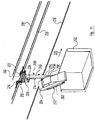
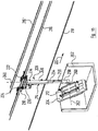
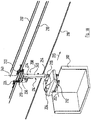
- the conveyor system 206 comprises a multiplicity of transport carriages 208, which in turn have a drive carriage 210 and a carrying carriage 212, which are coupled to one another via a telescopic device 214, which will be explained in detail below.
- a drive rail 216 with an I-profile extends above the plunge pool 202.
- a guide rail 218 with an upwardly open U-profile runs parallel to the drive rail 216.
- FIG Figure 1 The direction of movement in which the vehicle bodies 204 are conveyed by means of the conveyor system 206 is shown in FIG Figure 1 represented by an arrow 220.
- the drive rail 216 and the guide rail 218 are offset outward in relation to the center of the immersion tank 202 in the direction perpendicular to the direction of movement 220, the guide rail 218 extending further out than the drive rail 216.
- the drive car 210 is basically a construction that is known from conventional electric monorail systems. Each of these drive carriages 210 has a running gear 222 leading in the direction of movement 220, called “forerunner” in technical terminology, as well as a further running gear 224 lagging in the direction of movement 220, which is called “follower” in technical language.
- the precursor 222 and the follower 224 are equipped in a known manner with guide and support rollers, which are not specifically provided here with a reference number and which roll on different surfaces of the I-shaped profile of the drive rail 216. At least one of the rollers of the forerunner 222 or of the trailer 224 serves as a drive roller and for this purpose can be rotated by an electric motor 226 or 228. It may be sufficient if only the precursor 222 is driven.
- the transport carriage 208 driven by the drive carriage 210 can also negotiate inclines if the drive rail 216 has to run inclined in certain areas in order to adapt the conveying path to local conditions.
- the connecting frame 230 in turn carries a control device 232 in a known manner, which can communicate with the central control of the dip painting installation 200 and, if necessary, with the control devices 232 of the other drive carriages 210 present in the dip painting installation 200. In this way, a largely independent movement of the various transport carriages 208 is possible.
- the gear wheel 236 can be driven by means of a servomotor 242 which communicates with the control device 232 of the drive carriage 210 and which for this purpose drives a gear wheel 244 which engages in the external toothing 238 of the gear wheel 236.
- a servomotor 242 which communicates with the control device 232 of the drive carriage 210 and which for this purpose drives a gear wheel 244 which engages in the external toothing 238 of the gear wheel 236.
- the telescopic arm 234 can be rotated about the axis of rotation 240, depending on the direction of rotation of the pinion 244, both clockwise and counterclockwise.
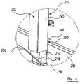
- the telescopic arm 234 comprises an upper telescopic member 246. This carries at its end remote from the gear 236 on a cross member 248 a guide roller 250 which is freely rotatable about a vertical axis of rotation 252 and runs in the U-profile of the guide rail 218, which is particularly in the Figures 5 and 6th can be seen. In this way, tilting of the telescopic arm 234 from the vertical in a plane perpendicular to the direction of movement 220 is prevented.
- the telescopic arm 234 comprises, in addition to the upper telescopic element 246, a middle telescopic element 254 and a lower telescopic element 256.
- the telescopic elements 246, 254 and 256 are displaceable relative to one another, whereupon will be discussed in more detail below.
- the carrying carriage 212 has two longitudinal spars 266 and 268 which are designed as a hollow profile and run parallel to one another and have a rectangular cross section and are connected in the center by a cross member 270 with a circular cross section.
- the pivot pin 260 of the carriage 256 is non-rotatably connected to the outer surface of the longitudinal spar 266 of the support carriage 212, the pivot pin 260 and the transverse strut 270 of the support carriage 212 running coaxially with one another.
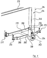
- Fastening means 272 are attached to the end faces of the longitudinal spars 266 and 268, by means of which a vehicle body 204 to be painted can be releasably fastened to the carrying carriage 212 in a manner known per se.
- the carriage 256 thus carries the carrying carriage 212 via the pivot 260 only on one side, so that the transport carriage 208 is designed as a whole as an L-shaped bracket.
- the transport carriage 208 can be aligned during its movement along the drive rail 216 such that the support carriage 212 with the fastening means 272 is arranged laterally offset with respect to the drive rail 216. This can ensure that no component of the conveyor system 206, e.g., among others, the drive rail 216 or the drive carriage 210, is arranged in the space perpendicularly above the carrying carriage 212 with the fastening means 272.
- the risk of the vehicle body 204 being contaminated by dirt, such as dust, oil or the like, falling from components of the conveyor system 206 is thus reduced.
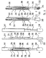
- the telescopic members 246, 254 and 256 of the telescopic arm 234 can be moved relative to one another.
- the cross-sections of the individual telescopic members 246, 254 and 256 are designed to be complementary to one another in such a way that the central telescopic member 254 can be moved in a guided manner in the upper telescopic member 246 and the carriage 256 in the central telescopic member 254.
- FIG Figure 9 An alternative embodiment of the telescopic arm 234 is shown in FIG Figure 9 shown in partially broken away views.
- the chain 278 runs over the drive pinion 276 of the servomotor 274 as well as over a first coupling pinion 292 and a second coupling pinion 294.
- the coupling pinions 292 and 294 each carry a coaxial spur gear, which in the views of Figure 9 cannot be seen.
- the external toothing of the spur gear on the coupling pinion 292 engages a rack 296 immovably connected to the upper telescopic element 246 of the telescopic arm 234 and is arranged in the upper region of the central telescopic element 254.
- the mode of operation of the cataphoretic dip painting system 200 described above is as follows:
- the vehicle bodies 204 to be painted are shown in FIG Figure 1 in an essentially horizontal orientation (cf. arrow 220) from a pretreatment station in which the vehicle bodies 204 are prepared in a known manner for the painting process by cleaning, degreasing, etc.
- the slide 256 has moved into its uppermost position in which the telescopic members 256, 254 and 256 of the telescopic arm 234 have moved into one another, so that the latter has its smallest possible length.
- the corresponding position is shown in perspective Figure 10 to recognize.
- the drive carriage 210 of the corresponding transport carriage 208 is fed with the aid of the electric motors 226 and 228 along the drive rail 216 onto the plunge pool 202, the associated carrying carriage 212 being carried along by the telescopic device 214.
- the guide roller 250 runs on the upper telescopic link 246 of the telescopic arm 234 in the U-profile of the guide rail 218, but this does not serve to take up weight.
- the weight of the transport trolley 208 and the vehicle body 204 attached to it is borne entirely by the drive rail 216 via the drive carriage 210.
- FIG Figure 12 With continued lowering of the slide 256 and continued rotation of the vehicle body 204 about the axis of rotation 262 of the pivot 260, a position is finally reached in which the vehicle body 204 is essentially vertical, as shown in FIG Figure 12 is shown.
- the vehicle body 204 is still relatively close to the entry-side end wall of the immersion tank 202 Pivot 260 and thus the vehicle body 204 are rotated further clockwise so that the vehicle body 204 begins to lie on its back, which is shown in FIG Figure 13 is shown.
- the speed of movement in the horizontal direction and the speed of rotation can be coordinated with one another in such a way that the front of the vehicle body 204 maintains approximately the same distance from the input-side end face of the immersion basin 202 during this immersion movement.
- the vehicle body 204 is completely immersed in the liquid paint.
- the vehicle body 204 is initially conveyed further through the plunge pool 202 in this position with the aid of the transport carriage 208 until it has moved closer to the end wall of the plunge pool 202 on the exit side.
- the dip painting installation 200 described can also be used for dip painting smaller objects (small goods).
- holding baskets (not specifically shown) can be fastened to the carrying trolleys 212, which contain, not shown, small-scale objects to be painted, for example in bulk. It goes without saying that such holding baskets are not guided through the plunge pool 202 in a position in which their loading opening faces downwards and objects to be coated could fall out.
- the telescopic arm 234 can be rotated about the vertical axis of rotation 240 via the servomotor 242.
- the telescopic arm 234 assumes a position with respect to its vertical axis of rotation 240 in which the pivot 260 is aligned on the slide 256 in such a way that its horizontal axis of rotation 262 is perpendicular to the direction of movement 220.
- the telescopic arm 234 is held in this position by a corresponding locking of the servomotor 242.
- the rotatability of the telescopic arm 234 about the vertical axis of rotation 240 comes in the Figures 1 and 10 to 18 kinematics shown only when the vehicle bodies 204 have left the plunge pool 202 and are removed from the transport carriage 208 for further processing.
- the trolleys 208 then have to be returned to the entrance of the dip painting installation 200 so that they can be reloaded there with vehicle bodies 204 that are still to be painted.
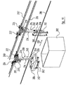
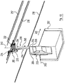
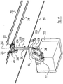
- the support carriage 212 is rotated about the vertical axis of rotation 240 relative to the connecting frame 230 of the drive carriage 210 until the pivot 260 on the carriage 256 is aligned parallel to the direction of movement 220 by actuating the servomotor 242 and, above it, the gear 236 on the upper telescopic link 246 of the telescopic arm 234 is twisted.
- the carrying carriage 212 is brought into a position in which its longitudinal spars 266 and 268 are vertical. This position is in the Figures 2 and 3 shown.
- a transport carriage 208 can be seen, which in this "return position" is guided back to the entrance of the dip painting system 200 on a drive rail 216 ', which runs parallel to the drive rail 216 and is connected to the latter via a curved rail that cannot be seen.
- the above based on the Figures 10 to 18 The described sequence of movements of the vehicle body 204 when passing through the plunge pool 202 is only an example.
- the structural design of the transport trolley 208 allows a large number of other kinematics that can each be adapted to the type of vehicle body 3.
- the vehicle body 204 can be guided through the plunge pool 202 on “roof up”.
- the further degree of freedom predetermined by the vertical axis of rotation 240 when the vehicle body 204 is guided through the plunge pool 202.
- a vehicle body 204 can also be guided transversely through it and not in the longitudinal direction, as is shown in FIGS Figures 10 to 18 is illustrated.
- the telescopic arm 234 can also be rotated about the vertical axis of rotation 240 to such an extent that the pivot 260 or its axis of rotation 262 encloses an angle between 0 and 90 ° with the direction of movement 220.
- the lower end region 258 of the carriage 256 which carries the horizontal pivot pin 262
- the horizontal axis of rotation 260 can be arranged near the center of gravity of the vehicle body 204 received by the support carriage 212. This leads to a more favorable force distribution during the sequence of movements for the vehicle body than is the case with known systems in which the axis of rotation is relatively far from the center of gravity of the vehicle body is absent.
Abstract
Description
Die Erfindung betrifft eine Tauchbehandlungsanlage zum Behandeln von Fahrzeugkarosserien gemäß dem Oberbegriff des Anspruchs 1.The invention relates to an immersion treatment system for treating vehicle bodies according to the preamble of claim 1.
Bei vom Markt her bekannten Systemen, wie sie in Tauchbehandlungsanlagen für Fahrzeugkarosserien eingesetzt werden und beispielsweise aus der
Bei diesem System, welches zum Transport von Fahr-zeugkarosserien in einer Tauchbehandlungsanlage eingesetzt wird, kann die Fahrzeugkarosserie zusätzlich in einer Vertikalbewegung abgesenkt oder angehoben werden. In diesem Fall kann für die Fahrzeugkarosserie ein Bewegungsablauf erzielt werden, der eine Überlagerung einer horizontalen Linearbewegung, einer vertikalen Linearbewegung und einer Drehung um die horizontale Drehachse ist. Dabei kann die Fahrzeugkarosserie auch noch um die horizontale Drehachse verdreht werden, nachdem sie durch die Vertikalbewegung in das Tauchbecken abgesenkt wurde. Auch hier bleibt die Grundausrichtung der Fahrzeugkarosserie gegenüber der Bewegungsrichtung der Translation unverändert.In this system, which is used to transport vehicle bodies in an immersion treatment system, the vehicle body can also be lowered or raised in a vertical movement. In this case For the vehicle body, a movement sequence can be achieved which is a superposition of a horizontal linear movement, a vertical linear movement and a rotation about the horizontal axis of rotation. The vehicle body can also be rotated about the horizontal axis of rotation after it has been lowered into the plunge pool by the vertical movement. Here, too, the basic orientation of the vehicle body remains unchanged in relation to the direction of movement of the translation.
Die Transportwägen derartiger Systeme müssen zum Eingang der Tauchbehandlungsanlagen zurückgeführt werden, nachdem die Fahrzeugkarosserie durch das Tauchbad hindurchgeführt worden ist und von dem Transportwagen abgenommen wurde. Der Transportwagen nimmt auf dem Rückweg vom Ausgang der Tauchbehandlungsanlage bis zu deren Eingang, auf dem er nicht mit einer Fahrzeugkarosserie beladen ist, denselben Raum in Anspruch, den er beim Durchfahren der Tauchbehandlungsanlage mit der Fahrzeugkarosserie benötigt. Der Bauraum für die Rückführung der Transportwägen muss entsprechend großzügig bemessen sein.The trolleys of such systems must be returned to the entrance of the immersion treatment plants after the vehicle body has been passed through the immersion bath and removed from the trolley. On the way back from the exit of the immersion treatment system to its entrance, where it is not loaded with a vehicle body, the transport vehicle takes up the same space that it needs when driving through the immersion treatment system with the vehicle body. The installation space for the return of the transport trolleys must be dimensioned accordingly generously.
Darüber hinaus ist die Bewegungskinematik im Hinblick auf die Dreh- bzw. Schwenkbewegung der Fahrzeugkarosserie bei vom Markt her bekannten Gegenständen auf die Drehung bzw. Verschwenkung um die horizontale Achse beschränkt. Um ein besseres Behandlungsergebnis, insbesondere Lackierergebnis, zu erzielen, besteht der Wunsch nach einer Erhöhung der Bewegungsfreiheitsgrade der Fahrzeugkarosserien im Tauchbad.In addition, the kinematics of movement with regard to the rotating or pivoting movement of the vehicle body is limited to the rotation or pivoting about the horizontal axis in objects known from the market. In order to achieve a better treatment result, in particular a painting result, there is a desire to increase the degrees of freedom of movement of the vehicle bodies in the immersion bath.
Aufgabe der vorliegenden Erfindung ist es, eine Tauchbehandlungsanlage der eingangs genannten Art so auszugestalten, dass einerseits die Bewegungsfreiheitsgrade der zu behandelnden Fahrzeugkarosserie und damit die Variabilität der Bewegungskinematik erhöht wird und andererseits der Raumbedarf des Transportwagens ohne daran befestigte Fahrzeugkarosserie verringert sein kann.The object of the present invention is to design an immersion treatment system of the type mentioned at the outset in such a way that, on the one hand, the degrees of freedom of movement of the vehicle body to be treated and thus the variability of the kinematics of movement are increased and, on the other hand, the Space requirement of the transport vehicle can be reduced without the vehicle body attached to it.
Diese Aufgabe wird erfindungsgemäß durch eine Tauchbehandlungsanlage gemäß Anspruch 1 gelöst.This object is achieved according to the invention by an immersion treatment system according to claim 1.
Erfindungsgemäß ist eine vertikale Drehbewegung für den zu behandelnden Gegenstand möglich, was dem gesamten Bewegungsablauf für den Gegenstand beispielsweise beim Durchfahren eines Tauchbeckens neue Möglichkeiten eröffnet. Zugleich bietet die vertikale Drehachse die Möglichkeit, die Befestigungseinrichtung in eine den örtlichen Gegebenheiten ggfs. besser angepasste Position zu bringen, wenn kein Gegenstand daran befestigt ist.According to the invention, a vertical rotary movement is possible for the object to be treated, which opens up new possibilities for the entire sequence of movements for the object, for example when passing through a dip tank. At the same time, the vertical axis of rotation offers the possibility of bringing the fastening device into a position that is better adapted to the local conditions if no object is fastened to it.
Es ist insbesondere günstig, wenn für die mindestens eine Fahrzeugkarosserie ein Bewegungsablauf erzielbar ist, der eine Überlagerung einer horizontalen Linearbewegung und einer Drehung um die vertikale Drehachse ist.It is particularly advantageous if a movement sequence can be achieved for the at least one vehicle body which is a superposition of a horizontal linear movement and a rotation about the vertical axis of rotation.
Dieses Konzept bedeutet nicht, dass bei einer horizontalen Linearbewegung der Fahrzeugkarosserie auch stets eine Drehung um die vertikale Drehachse erfolgt. Genauso wenig muss die Fahrzeugkarosserie bei einer Drehung um die vertikale Drehachse zwingend in horizontaler Richtung bewegt werden. Es genügt, wenn das Hängebahnsystem die Möglichkeit bietet, die Bewegungsfreiheitsgrade gleichzeitig zu nutzen. Auch ist nicht ausgeschlossen, dass die Befestigungseinrichtung noch in weiteren Bewegungsfreiheitsgraden bewegt werden kann. Dies kann insbesondere im Hinblick auf die Raumersparnis beim Führen des unbeladenen Transportwagens nützlich sein.This concept does not mean that with a horizontal linear movement of the vehicle body there is always a rotation about the vertical axis of rotation. Nor does the vehicle body necessarily have to be moved in the horizontal direction when it is rotated about the vertical axis of rotation. It is sufficient if the overhead conveyor system offers the possibility of using the degrees of freedom of movement at the same time. It is also not ruled out that the fastening device can still be moved with further degrees of freedom of movement. This can be particularly useful in terms of saving space when guiding the unloaded trolley.
Vorteilhaft umfasst der Transportwagen einen vertikal verfahrbaren Schlitten, von welchem die Befestigungseinrichtung mitgeführt wird. Auf diese Weise wird der Befestigungsreinrichtung bzw. der daran befestigten Fahrzeugkarosserie ein weiterer Bewegungsfreiheitsgrad hinzugefügt.The trolley advantageously comprises a vertically movable slide from which the fastening device is carried. In this way, a further degree of freedom of movement is added to the fastening device or to the vehicle body fastened to it.
Dies kann in günstige Weise realisiert werden, wenn der Transportwagen eine in vertikaler Richtung ein- oder ausfahrbare Teleskopeinrichtung umfasst, welche den Schlitten führt.This can be implemented in a favorable manner if the transport carriage comprises a telescopic device which can be retracted or extended in the vertical direction and which guides the slide.
Es ist günstig, wenn der Transportwagen als Antriebsmittel einen an der Schiene motorisch verfahrbaren Antriebswagen umfasst. Durch diese Ausgestaltung ist es möglich, Antriebswägen und Antriebsschienen zu verwenden, wie sie aus anderen Anwendungsgebieten bereits bekannt sind. Es lassen sich dadurch alle dort bereits eingesetzten Technologien und Steuerungsverfahren nutzen, die bereits erprobt und bewährt sind.It is favorable if the transport carriage comprises a drive carriage which can be moved by a motor on the rail as the drive means. This configuration makes it possible to use drive carriages and drive rails as they are already known from other areas of application. This means that all technologies and control methods that have already been used there can be used that have already been tried and tested.
In diesem Fall kann die Teleskopeinrichtung um die vertikale Drehachse verdrehbar an dem Antriebswagen des Transportwagens gelagert sein.In this case, the telescopic device can be mounted on the drive carriage of the transport carriage so that it can be rotated about the vertical axis of rotation.
Eine besonders große Variabilität des Bewegungsablaufs für den Gegenstand wird erzielt, wenn die Befestigungseinrichtung außerdem um eine horizontale Drehachse verdrehbar gelagert ist. Somit kann in Verbindung mit dem vertikal verfahrbaren Schlitten für den Gegenstand ein Bewegungsablauf erzielt werden, der eine Überlagerung einer horizontalen Linearbewegung, einer vertikalen Linearbewegung, einer Drehung um die vertikale Drehachse ist. Wenn auch die horizontale Drehachse realisiert ist, kann in Verbindung mit dem vertikal verfahrbaren Schlitten für den Gegenstand ein Bewegungsablauf erzielt werden, der eine Überlagerung einer horizontalen Linearbewegung, einer vertikalen Linearbewegung, einer Drehung um die vertikale Drehachse ist und einer Drehung um die horizontale Drehachse ist. Auch hier bedeutet dies nicht, dass der Bewegungsablauf stets eine derartige Überlagerung ist; es reicht aus, wenn die Bewegungsfreiheitsgrade gleichzeitig genutzt werden können. Die horizontale Drehachse verläuft vorzugsweise etwa senkrecht zur Bewegungsrichtung des Transportwagens.A particularly large variability in the sequence of movements for the object is achieved if the fastening device is also mounted so that it can be rotated about a horizontal axis of rotation. Thus, in connection with the vertically displaceable slide for the object, a movement sequence can be achieved which is a superposition of a horizontal linear movement, a vertical linear movement, a rotation about the vertical axis of rotation. If the horizontal axis of rotation is also implemented, a movement sequence can be achieved in connection with the vertically movable slide for the object, which is a superposition of a horizontal linear movement, a vertical linear movement, a rotation about the vertical axis of rotation and a Is rotation about the horizontal axis of rotation. Here, too, this does not mean that the sequence of movements is always such a superposition; it is sufficient if the degrees of freedom of movement can be used at the same time. The horizontal axis of rotation is preferably approximately perpendicular to the direction of movement of the trolley.
Ausführungsbeispiele der Erfindung werden nachstehend anhand der beigefügten Zeichnungen näher erläutert. In diesen zeigen:
- Figur 1
- in einer Seitenansicht eine kataphoretische Tauch- lackieranlage für Fahrzeugkarosserien;
- Figuren 2 und 3
- perspektivisch aus unterschiedlichen Blick- richtungen einen Transportwagen mit einem Teleskop- arm, wie er zur Förderung der zu lackierenden Fahr- zeugkarosserien bei der Tauchlackieranlage von Fi- gur 1 eingesetzt wird, während des Rückführvorgan- ges vom Ausgang der Anlage zu deren Eingang;
- Figur 4
- perspektivisch und in größerem Maßstab eine Detail- ansicht eines Antriebswagens des Transportwagens, wie er bei der kataphoretischen Tauchlackieranlage von
Figur 1 eingesetzt wird, wobei ein Mechanismus zum Drehen des Teleskoparms gezeigt ist; - Figuren 5 und 6
- perspektivisch und in größerem Maßstab eine Detailansicht aus unterschiedlichen Blickrichtungen einer Seitenführung des Teleskoparms;
Figur 7- perspektivisch eine Detailansicht in größerem Maß- stab einer Befestigungseinrichtung des Transportwa- gens, wie er bei der Tauchlackieranlage von
Figur 1 eingesetzt wird; - Figuren 8A bis 8E
- verschiedene Ansichten eines ersten Aus- führungsbeispiels des Teleskoparms, wie er beim Transportwagen der kataphoretischen Tauchlackieran- lage von
Figur 1 eingesetzt wird,Figuren 9A bis 9E verschiedene Ansichten eines zweiten Ausführungs- beispiels des Teleskoparms, wie er bei dem Trans- portwagen der kataphoretischen Tauchlackieranlage vonFigur 1 eingesetzt wird; - Figuren 10 bis 18
- perspektivisch verschiedene Phasen beim Eintauchen einer Fahrzeugkarosserie in das Tauch- becken der kataphoretischen Tauchlackieranlage von
Figur 1 .
- Figure 1
- a side view of a cataphoretic dip painting system for vehicle bodies;
- Figures 2 and 3
- perspectively from different directions of view a transport trolley with a telescopic arm, as it is used to convey the vehicle bodies to be painted in the dip painting plant of FIG. 1, during the return process from the outlet of the plant to its entrance;
- Figure 4
- in perspective and on a larger scale, a detailed view of a drive vehicle of the transport vehicle, as it is in the cataphoretic dip painting system of
Figure 1 is deployed showing a mechanism for rotating the telescopic arm; - Figures 5 and 6
- in perspective and on a larger scale, a detailed view from different viewing directions of a side guide of the telescopic arm;
- Figure 7
- in perspective, a detailed view on a larger scale of a fastening device of the transport vehicle, as it is in the dip painting system of
Figure 1 is used; - Figures 8A through 8E
- various views of a first exemplary embodiment of the telescopic arm, as it is in the transport trolley of the cataphoretic dip painting system from
Figure 1 is used,characters 9A to 9E various views of a second exemplary embodiment of the telescopic arm, as it is in the transport car of the cataphoretic dip painting system fromFigure 1 is used; - Figures 10 to 18
- different phases in perspective when a vehicle body is immersed in the dip tank of the cataphoretic dip painting plant from
Figure 1 .
In den
Die Fahrzeugkarosserien 204 werden mit Hilfe eines Fördersystems 206 durch die Anlage und insbesondere durch das Tauchbecken 202 und den darin befindlichen Lack geführt. Das Fördersystem 206 umfasst eine Vielzahl von Transportwagen 208, die ihrerseits einen Antriebswagen 210 und einen Tragwagen 212 aufweisen, welche über eine weiter unten noch im Detail erläuterte Teleskopeinrichtung 214 miteinander gekoppelt sind.The
Über dem Tauchbecken 202 erstreckt sich eine Antriebsschiene 216 mit einem I-Profil, wie sie bei herkömmlichen Elektrohängebahnen eingesetzt wird. Unterhalb der Antriebsschiene 216 und oberhalb des Tauchbeckens 202 verläuft parallel zur Antriebsschiene 216 eine Führungsschiene 218 mit einem nach oben offenen U-Profil.A
Die Bewegungsrichtung, in welcher die Fahrzeugkarosserien 204 mittels des Fördersystems 206 gefördert werden, ist in
Bei den Antriebswagen 210 handelt es sich im Grundsatz um eine Konstruktion, die von herkömmlichen Elektrohängebahnen her bekannt ist. Jeder dieser Antriebswagen 210 besitzt ein in Bewegungsrichtung 220 vorauseilendes Fahrwerk 222, in der Fachsprache "Vorläufer" genannt, sowie ein in Bewegungsrichtung 220 nacheilendes weiteres Fahrwerk 224, welches in der Fachsprache "Nachläufer" genannt wird. Vorläufer 222 und Nachläufer 224 sind in bekannter Weise mit Führungs- und Tragrollen ausgestattet, die hier nicht eigens mit einem Bezugszeichen versehen sind und an verschiedenen Flächen des I-förmigen Profils der Antriebsschiene 216 abrollen. Mindestens eine der Rollen des Vorläufers 222 bzw. des Nachläufers 224 dient als Antriebsrolle und ist hierzu durch einen Elektromotor 226 bzw. 228 drehbar. Gegebenenfalls kann es ausreichen, wenn lediglich der Vorläufer 222 angetrieben ist. Der über den Antriebswagen 210 angetriebene Transportwagen 208 kann gegebenenfalls auch Steigungen überwinden, wenn die Antriebsschiene 216 in bestimmten Bereichen geneigt verlaufen muss, um den Förderweg an örtliche Gegebenheiten anzupassen.The
Vorläufer 222 und Nachläufer 224 jedes Antriebswagens 210 sind durch einen Verbindungsrahmen 230 miteinander verbunden, der insbesondere in den
Der Verbindungsrahmen 230 trägt wiederum in bekannter Weise eine Steuereinrichtung 232, welche mit der zentralen Steuerung der Tauchlackieranlage 200 und ggfs. mit den Steuereinrichtungen 232 der anderen in der Tauchlackieranlage 200 vorhandenen Antriebswagen 210 kommunizieren kann. Auf diese Weise ist eine weitgehend unabhängige Bewegung der verschiedenen Transportwagen 208 möglich.The connecting
Die Teleskopeinrichtung 214, welche den Antriebswagen 210 mit dem Tragwagen 212 koppelt, umfasst einen dreigliedrigen vertikal verlaufenden Teleskoparm 234, welcher in seiner Länge veränderbar ist. Dieser ist an seinem oberen Ende stirnseitig drehfest mit einem Zahnrad 236 mit einer Außenverzahnung 238 verbunden, so dass die Längsachse des Teleskoparms 234 und die Drehachse 240 des Zahnrads 236 (vgl.
Das Zahnrad 236 kann mittels eines mit der Steuereinrichtung 232 des Antriebswagens 210 kommunizierenden Stellmotors 242 angetrieben werden, welcher dazu ein in die Außenverzahnung 238 des Zahnrads 236 eingreifendes Zahnrad 244 antreibt. Somit kann der Teleskoparm 234 um die Drehachse 240 je nach Drehrichtung des Ritzels 244 sowohl im Uhrzeigersinn als auch gegen den Uhrzeigersinn verdreht werden.The
Der Stellmotor 242 und das Ritzel 244 sind der Übersichtlichkeit halber lediglich in
Der Teleskoparm 234 umfasst ein oberes Teleskopglied 246. Dieses trägt an seinem vom Zahnrad 236 abliegenden Ende an einem Querträger 248 eine Führungsrolle 250, welche frei um eine vertikale Drehachse 252 verdrehbar ist und in dem U-Profil der Führungsschiene 218 läuft, was insbesondere in den
Der Teleskoparm 234 umfasst neben dem oberen Teleskopglied 246 ein mittleres Teleskopglied 254 sowie ein unteres Teleskopglied 256. Die Teleskopglieder 246, 254 und 256 sind relativ zueinander verschiebbar, worauf weiter unten nochmals näher eingegangen wird.The
Das untere Teleskopglied 256 dient als in dem mittleren Teleskopglied 254 verfahrbarer Schlitten 256 und wird nachstehend als solcher bezeichnet. Am unteren freien Endbereich 258 des Schlittens 256 ist ein Drehzapfen 260 gelagert. Dieser definiert eine in den
Wie insbesondere in den
Der Schlitten 256 trägt den Tragwagen 212 über den Drehzapfen 260 somit nur an einer Seite, so dass der Transportwagen 208 insgesamt als L-förmiger Bügel ausgebildet ist. Der Transportwagen 208 kann während seiner Bewegung entlang der Antriebsschiene 216 so ausgerichtet sein, dass der Tragwagen 212 mit den Befestigungsmitteln 272 seitlich gegenüber der Antriebschiene 216 versetzt angeordnet ist. Dadurch kann sichergestellt werden, dass keine Komponente des Fördersystems 206, z.B. unter anderem die Antriebsschiene 216 oder der Antriebswagen 210, in dem Raum senkrecht über dem Tragwagen 212 mit den Befestigungsmitteln 272 angeordnet ist. Die Gefahr einer Verunreinigung der Fahrzeugkarosserie 204 durch von Komponenten des Fördersystems 206 herabfallenden Schmutz, wie z.B. Staub, Öl oder dergleichen, ist somit verringert.The
Wie oben erwähnt, können die Teleskopglieder 246, 254 und 256 des Teleskoparms 234 relativ zueinander bewegt werden. Dazu sind die Querschnitte der einzelnen Teleskopglieder 246, 254 und 256 derart komplementär zueinander ausgebildet, dass das mittlere Teleskopglied 254 in dem oberen Teleskopglied 246 und der Schlitten 256 in dem mittleren Teleskopglied 254 geführt verschoben werden kann.As mentioned above, the
Bei einem in
Wird nun der Stellmotor 274 derart von der Steuereinrichtung 232 des Transportwagens 208 angesteuert, dass sich das Antriebsritzel 276 in
Eine alternative Ausbildung des Teleskoparms 234 ist in
Wird nun der Stellmotor 274 derart von der Steuereinrichtung 232 des Transportwagens 208 angesteuert, dass sich das Antriebsritzel 276 in
Wird das Kettenritzel 276 im Uhrzeigersinn verdreht, so wird der Schlitten 256 in das mittlere Teleskopglied 254 und gleichzeitig dieses in das obere Teleskopglied 246 eingefahren.If the
Bei hier nicht gezeigten Abwandlungen kann die Hub-/Senkbewegung der Teleskopglieder 246 und 254 und des Schlittens 256 auch durch eine Schubkette oder ähnliche Vorrichtungen bewirkt werden.In the case of modifications not shown here, the lifting / lowering movement of the
Die Funktionsweise der oben beschriebenen kataphoretischen Tauchlackieranlage 200 ist folgende:
Die zu lackierenden Fahrzeugkarosserien 204 werden in
The
Der Schlitten 256 ist dabei in seine oberste Position verfahren, in welcher die Teleskopglieder 256, 254 und 256 des Teleskoparms 234 ineinander gefahren sind, so dass letzterer seine geringstmögliche Länge aufweist. Die entsprechende Position ist perspektivisch in
Wenn sich der Transportwagen 208 der auf der Eintrittsseite befindlichen Stirnwand des Tauchbeckens 202 nähert, wird der Schlitten 256, welcher die Fahrzeugkarosserie 204 über den Transportwagen 208 trägt, progressiv abgesenkt, indem mit Hilfe des Stellmotors 274 der Teleskoparm 234 in oben beschriebener Weise ausgefahren wird. Sobald die Front der Fahrzeugkarosserie 204 über die Stirnwand des Tauchbeckens 202 hinaus ins Innere des Tauchbeckens 202 ragt, wird gleichzeitig mit Hilfe des Getriebemotors 264 der Drehzapfen 260 und damit der Tragwagen 212 mit den Befestigungsmitteln 272 und daran befestigter Fahrzeugkarosserie 204 um die Drehachse 262 verdreht. In diesem Bereich ist also die Gesamtbewegung der Fahrzeugkarosserie 204 als Überlagerung dreier Bewegungen zu verstehen, nämlich einer horizontalen Linearbewegung (Pfeil 220) entlang der Antriebsschiene 216, einer vertikalen Linearbewegung entlang der Drehachse 240 und damit auch entlang der Längsachse des Teleskoparms 234 und einer Drehbewegung um die Drehachse 262 des Drehzapfens 260, die in der Sicht der
Unter fortgesetztem Absenken des Schlittens 256 und fortgesetzter Drehung der Fahrzeugkarosserie 204 um die Drehachse 262 des Drehzapfens 260 wird schließlich eine Position erreicht, in welcher die Fahrzeugkarosserie 204 im Wesentlichen senkrecht steht, wie dies in
Spätestens in dem Moment, in dem die Fahrzeugkarosserie 204 vollständig "auf dem Rücken" und damit wieder horizontal liegt und der in
Sodann beginnt der Austauchvorgang der Fahrzeugkarosserie 204. Dieser stellt sich wiederum als Überlagerung von drei Bewegungen dar, nämlich der horizontalen Linearbewegung in Förderrichtung 220, der Vertikalbewegung entlang der Drehachse 240 und damit auch entlang der Längsachse des Teleskoparms 234 und der Drehbewegung um die Drehachse 262 des Drehzapfens 260. Zunächst wird die Fahrzeugkarosserie 204 durch Weiterverdrehen des Drehzapfens 260 im Uhrzeigersinn vertikal gestellt, was in den
Die beschriebene Tauchlackieranlage 200 kann auch zum Tauchlackieren kleinerer Gegenstände (Kleingüter) verwendet werden. Dazu können beispielsweise nicht eigens gezeigte Haltekörbe an den Tragwagen 212 befestigt werden, welche nicht dargestellte kleinteilige, zu lackierende Gegenstände beispielsweise in loser Schüttung enthalten. Es versteht sich, dass solche Haltekörbe nicht in einer Position durch das Tauchbecken 202 geführt werden, in welcher ihre Beschickungsöffnung nach unten weist und zu beschichtende Gegenstände herausfallen könnten.The
Wie oben erläutert, kann der Teleskoparm 234 über den Stellmotor 242 um die vertikale Drehachse 240 verdreht werden. Bei der in den
Die Verdrehbarkeit des Teleskoparms 234 um die vertikale Drehachse 240 kommt bei der in den
Die Übergabe des Transportwagens 208 von der Antriebsschiene 216 auf die Antriebsschiene 216' kann auch mittels einer Querverschiebung erfolgen, ohne dass dazu ein die Antriebsschienen 216, 216' verbindendes Schienenkurvenstück nötig wäre.The transfer of the
Durch die Drehung des Tragwagens 212 und dessen Vertikalstellung gegenüber dem Antriebswagen 210 wird der Platzbedarf für den Transportwagen 208 auf dem Rückweg vom Ausgang der Tauchlackieranlage 200 zu deren Eingang verringert.As a result of the rotation of the
Der oben anhand der
Alternativ ist es möglich, dass die Drehachse 262 des Tragwagens 212 knapp über dem Flüssigkeitsspiegel der im Tauchbad 202 befindlichen Badflüssigkeit geführt wird. In diesem Fall wird die Fahrzeugkarosserie "Dach unten" durch das Tauchbecken 202 geführt. Dabei kann erreicht werden, dass weder der Tragwagen 212 noch der Schlitten 256 mit Badflüssigkeit in Kontakt kommen, wodurch die Gefahr verringert ist, Badflüssigkeit von einem Tauchbad ins nächste Tauchbad zu verschleppen und Schmiermittel in die Tauchbäder einzutragen.Alternatively, it is possible that the axis of
Es ist beispielsweise auch möglich, den durch die vertikale Drehachse 240 vorgegebenen weiteren Freiheitsgrad zu nutzen, wenn die Fahrzeugkarosserie 204 durch das Tauchbecken 202 geführt wird. So kann eine Fahrzeugkarosserie 204 bei entsprechenden Abmessungen des Tauchbeckens 202 auch quer durch dieses geführt werden und nicht in Längsrichtung, wie es in den
Für die Fahrzeugkarosserie 204 kann somit ein Bewegungsablauf erzielt werden, der als Überlagerung von vier Bewegungen verstanden werden kann, nämlich einer horizontalen Linearbewegung (entsprechend der Bewegungsrichtung 220), einer vertikalen Linearbewegung entlang der Drehachse 240 und damit entlang der Längsachse des Teleskoparms 234, einer Drehbewegung um die horizontale Drehachse 262 des Drehzapfens 260 und einer Drehbewegung um die vertikale Drehachse 240 des Teleskoparms 234.A sequence of movements can thus be achieved for the
Das als Hängebahnsystem ausgebildete Fördersystem 206 erfordert keine weiteren Aufbauten rechts und/oder links des Tauchbeckens 202, wie sie bei anders konzipierten Anlagen notwendig sind. Dadurch kann die Tauchlackieranlage 200 insgesamt verhältnismäßig schmal gehalten werden.The
Durch die seitliche Lagerung des Tragwagens 212 gibt es darüber hinaus keine Abschattungen der Fahrzeugkarosserie 204 durch weitere Bauteile des Transportwagens 208, die im Tauchbad entsprechend aufwändig durch eine geeignete Kinematik und/oder eine längere Verweilzeit im Tauchbad kompensiert werden müssten.Due to the lateral mounting of the
Beim Führen der Fahrzeugkarosserie 204 durch das Tauchbad wird der untere Endbereich 258 des Schlittens 256, welcher den horizontalen Drehzapfen 262 trägt, in die Badflüssigkeit abgesenkt. Dadurch kann die horizontale Drehachse 260 nahe dem Schwerpunkt der von dem Tragwagen 212 aufgenommenen Fahrzeugkarosserie 204 angeordnet sein. Dies führt zu einer günstigeren Kraftverteilung beim Bewegungsablauf für die Fahrzeugkarosserie als es bei bekannten Systemen der Fall ist, bei denen die Drehachse verhältnismäßig weit vom Schwerpunkt der Fahrzeugkarosserie abliegt.As the
Claims (7)
- A dip treatment plant for the treatment of vehicle bodies, comprisinga) at least one dip bath (202) which can be filled with a treatment liquid into which vehicle bodies (204) to be treated can be dipped completely;b) a conveyor system (206) which can move the vehicle bodies (204) to be treated up to the dip bath (202), completely into the interior of the dip bath (202), out of the dip bath (202) and away from the latter, havingcharacterized in thatba) at least one transport carriage (208) comprising a fastening device (212, 272) to which at least one vehicle body (204) can be fastened;bb) at least one rail (216) supporting the transport carriage (208);bc) at least one drive means (222, 224) for moving the transport carriage (208) along the rail (216);c) the conveyor system (206) is an overhead conveyor system (206);d) the fastening device (212, 272) is mounted such that it is rotatable about a vertical axis of rotation (240);e) a rotation of the fastening device (212, 272) about the vertical axis of rotation (240) is achievable while the at least one vehicle body (204) is dipped in the at least one dip bath (202).
- Dip treatment plant according to claim 1, which is configured such that a movement sequence is achievable for the at least one vehicle body (204), which is a superposition of a horizontal linear movement and a rotation about the vertical axis of rotation (240).
- Dip treatment plant according to claim 1 or 2, characterized in that the transport carriage (208) comprises a vertically movable skid (256) by which the fastening device (212, 272) is entrained.
- Dip treatment plant according to claim 3, characterized in that the transport carriage (208) comprises a telescopic device (214) which can be retracted or extended in the vertical direction and which guides the skid (256).
- Dip treatment plant according to one of claims 1 to 4, characterized in that the transport carriage (208) comprises as drive means (210) a drive carriage (210) which can be moved by motor on the rail (216).
- Dip treatment plant according to claim 5 with reference to claim 4, characterized in that the telescopic device (214) is mounted such that it is rotatable about the vertical axis of rotation (240) on the drive carriage (210) of the transport carriage.
- Dip treatment plant according to any one of claims 1 to 6, characterized in that the fastening device (212, 272) is also mounted such that it is rotatable about a horizontal axis of rotation (262).
Priority Applications (1)
| Application Number | Priority Date | Filing Date | Title |
|---|---|---|---|
| PL09713204T PL2242711T3 (en) | 2008-02-21 | 2009-01-27 | Overhead conveyor system, dip coating line comprising said system, and use of said conveyor |
Applications Claiming Priority (2)
| Application Number | Priority Date | Filing Date | Title |
|---|---|---|---|
| DE102008010400A DE102008010400A1 (en) | 2008-02-21 | 2008-02-21 | Monorail system and dip treatment plant with such |
| PCT/EP2009/000497 WO2009103401A1 (en) | 2008-02-21 | 2009-01-27 | Overhead conveyor system and dip coating line comprising said system |
Publications (3)
| Publication Number | Publication Date |
|---|---|
| EP2242711A1 EP2242711A1 (en) | 2010-10-27 |
| EP2242711B1 EP2242711B1 (en) | 2011-08-24 |
| EP2242711B2 true EP2242711B2 (en) | 2021-12-08 |
Family
ID=40474745
Family Applications (1)
| Application Number | Title | Priority Date | Filing Date |
|---|---|---|---|
| EP09713204.7A Active EP2242711B2 (en) | 2008-02-21 | 2009-01-27 | Overhead conveyor system, dip coating line comprising said system, and use of said conveyor |
Country Status (15)
| Country | Link |
|---|---|
| US (1) | US8522957B2 (en) |
| EP (1) | EP2242711B2 (en) |
| JP (1) | JP5390538B2 (en) |
| KR (1) | KR101629036B1 (en) |
| CN (1) | CN101952185B (en) |
| AT (1) | ATE521558T1 (en) |
| BR (1) | BRPI0907581A2 (en) |
| CA (1) | CA2715405C (en) |
| DE (1) | DE102008010400A1 (en) |
| ES (1) | ES2371734T3 (en) |
| MX (1) | MX2010009041A (en) |
| PL (1) | PL2242711T3 (en) |
| RU (1) | RU2518128C2 (en) |
| UA (1) | UA99179C2 (en) |
| WO (1) | WO2009103401A1 (en) |
Families Citing this family (15)
| Publication number | Priority date | Publication date | Assignee | Title |
|---|---|---|---|---|
| DE102010004974B4 (en) * | 2010-01-18 | 2021-06-10 | Eisenmann Se | Conveyor system for the transport of objects and immersion treatment system with such |
| DE102010001366A1 (en) * | 2010-01-29 | 2011-08-04 | Dürr Systems GmbH, 74321 | System for treatment of surface of car body, has conveying apparatus comprising workpiece holders with raisable and lowerable stroke part at which rotatable rotary part is held relative to base part |
| JP5560974B2 (en) * | 2010-07-06 | 2014-07-30 | 株式会社ダイフク | Traveling immersion processing equipment |
| DE102011101278B4 (en) * | 2011-05-12 | 2017-01-26 | Eisenmann Se | Plant for treating, in particular for the cataphoretic dip painting of objects, in particular of vehicle bodies |
| US9534311B2 (en) * | 2012-08-03 | 2017-01-03 | Fanuc America Corporation | Robotic pretreatment and primer electrodeposition system |
| CN103041952B (en) * | 2012-12-10 | 2016-08-03 | 上海通领汽车科技股份有限公司 | Automotive upholstery resistance plating machine |
| ITMI20132152A1 (en) * | 2013-12-20 | 2015-06-21 | Geico Spa | PLANT FOR SHELL IMMERSION TREATMENT |
| DE102014219764A1 (en) * | 2014-09-30 | 2016-03-31 | Dürr Systems GmbH | Conveying device, drying plant and method for conveying workpieces |
| ES2565561B2 (en) * | 2015-11-26 | 2016-08-17 | Pablo Germade Castiñeiras | Transport system for packaging machine |
| AT520118B1 (en) * | 2017-06-30 | 2021-06-15 | Alex Fehberger | Transport device and process for dip painting |
| CN111196474A (en) * | 2018-11-16 | 2020-05-26 | 北汽福田汽车股份有限公司 | Rotary traveling conveying system and skid conveying method |
| CN109653040B (en) * | 2018-11-21 | 2021-07-06 | 中车青岛四方机车车辆股份有限公司 | Track beam for line switching |
| CN110000061A (en) * | 2019-05-08 | 2019-07-12 | 太仓卡兰平汽车零部件有限公司 | A kind of zinc-aluminium microplate coating spring apparatus for production line combination |
| US11072501B2 (en) * | 2019-06-27 | 2021-07-27 | Sst Systems, Inc. | Finishing system and method of operating |
| CN114313804B (en) * | 2022-03-07 | 2022-05-27 | 常州市达力塑料机械有限公司 | Transfer mechanism for coil |
Citations (21)
| Publication number | Priority date | Publication date | Assignee | Title |
|---|---|---|---|---|
| GB1343019A (en) † | 1970-01-05 | 1974-01-10 | Garrison W H | Galvanizing apparatus |
| US3952699A (en) † | 1973-02-12 | 1976-04-27 | Heinz Durr | Method and apparatus for treating a workpiece at a treating station |
| DE2902352A1 (en) † | 1979-01-22 | 1980-07-24 | B & W Transportsysteme Gmbh | METHOD AND DEVICE FOR PRESERVING WORKPIECES BY COATING IN THE DIVING METHOD |
| EP0015848A1 (en) † | 1979-03-06 | 1980-09-17 | ALPASONIC S.A. Société dite: | Manoeuvring device for articles to be treated in a processing plant |
| EP0110525A1 (en) † | 1982-11-16 | 1984-06-13 | Miguel Agullo Negui | Improvements in washing/finishing machines for mechanical parts |
| DE3612485A1 (en) † | 1986-04-14 | 1986-09-04 | Roland 5100 Aachen Hantsch | Muscle-powered vehicle |
| US4772374A (en) † | 1983-11-14 | 1988-09-20 | Prime-Coat Technology, Inc. | Electrodeposition system and method therefor |
| DE8810999U1 (en) † | 1988-08-31 | 1989-07-06 | Hestermann, Gerhard, 7990 Friedrichshafen, De | |
| JPH108292A (en) † | 1996-06-24 | 1998-01-13 | Central Motor Co Ltd | Surface treating device and surface treatment |
| DE19641048A1 (en) † | 1996-10-04 | 1998-04-16 | Flaekt Ab | Method for inserting and removing workpieces, in particular vehicle bodies, device and system for the surface treatment of workpieces |
| EP1319444A2 (en) † | 2001-12-12 | 2003-06-18 | WMV Apparatebau GmbH & Co.KG | Device for treatment of articles |
| WO2003059793A1 (en) † | 2002-01-21 | 2003-07-24 | Epv-Tec Gmbh | Device and method for the surface treatment of parts |
| WO2003070545A1 (en) † | 2002-02-20 | 2003-08-28 | Dürr Systems GmbH | Device and method for handling workpieces in particular vehicle chassis |
| DE10261337A1 (en) † | 2002-12-28 | 2004-07-08 | Volkswagen Ag | Process for conveying car bodies in an assembly line |
| US20040149542A1 (en) † | 2003-01-24 | 2004-08-05 | Hisashi Kyotani | Conveyance method and apparatus for processing step |
| DE10309328A1 (en) † | 2003-03-04 | 2004-09-16 | Bayerische Motoren Werke Ag | Crash sensor system for motorcycles consists of e.g. pressure sensor to detect travel of front wheel or forks and their impact on parts behind during frontal collision |
| WO2004096448A1 (en) † | 2003-04-26 | 2004-11-11 | Basf Coatings Ag | Electrodeposition painting method and throughflow system for carrying out said method |
| US20070000758A1 (en) † | 2005-06-29 | 2007-01-04 | Taikisha Ltd. | Conveyor System |
| DE10125032B4 (en) † | 2000-05-23 | 2007-11-08 | Suzuki K.K., Hamamatsu | Rear suspension for a motorcycle |
| WO2009083081A1 (en) † | 2007-12-28 | 2009-07-09 | Eisenmann Anlagenbau Gmbh & Co. Kg | Immersion treatment system |
| DE102007063061A1 (en) † | 2007-12-28 | 2009-07-09 | Eisenmann Anlagenbau Gmbh & Co. Kg | Dip treatment system i.e. cataphoretic dip painting system, for vehicle body, has transport trolley with carriage, where pivot pin defining rotation axis is supported at carriage such that total motion sequence for object is achieved |
Family Cites Families (14)
| Publication number | Priority date | Publication date | Assignee | Title |
|---|---|---|---|---|
| US3658197A (en) * | 1970-06-01 | 1972-04-25 | Lockheed Aircraft Corp | Programmable apparatus for conveying articles through successive process steps |
| US3861352A (en) * | 1972-11-24 | 1975-01-21 | Thorvald F Hammer | Automatic galvanizing machines |
| DE2737917C2 (en) | 1977-08-23 | 1984-04-26 | Hübers & Meier, 4190 Bocholt | Impregnation device equipped with a centrifuge |
| CA2026174C (en) * | 1989-09-26 | 2000-01-18 | Kiyohiro Ichinose | Surface treatment apparatus |
| TW237435B (en) * | 1992-01-21 | 1995-01-01 | Nakanishi Kinzoku Kogyo Kk | |
| JPH0625220U (en) * | 1992-09-01 | 1994-04-05 | 株式会社椿本チエイン | Inter-vehicle distance detection device for carriers that can change the direction of conveyed items |
| DE9408846U1 (en) * | 1994-05-30 | 1994-09-01 | Ehrenleitner Franz | Carrying device |
| DE4326563A1 (en) * | 1993-08-07 | 1995-02-09 | Rainer F Tracksdorf | Conveying apparatus for vehicle bodies |
| US5972112A (en) * | 1997-10-03 | 1999-10-26 | Acco Systems, Inc. | Dip tank workpiece carrier with rocking frame |
| DE10103837B4 (en) | 2001-01-29 | 2005-09-29 | EISENMANN Fördertechnik GmbH & Co. KG | Plant for treating, in particular for painting objects, in particular vehicle bodies |
| DE10306826B4 (en) * | 2003-02-19 | 2007-06-14 | Manz Galvanotechnik Gmbh | Device for the surface treatment of bulk solids in liquids |
| JP2004315837A (en) * | 2003-04-11 | 2004-11-11 | Trinity Ind Corp | Treatment system for workpiece |
| JP4557683B2 (en) * | 2003-12-26 | 2010-10-06 | 株式会社大気社 | Transport equipment |
| DE102006042632A1 (en) | 2006-08-31 | 2008-03-20 | Holder, Jochen | Process for coating components with a paint |
-
2008
- 2008-02-21 DE DE102008010400A patent/DE102008010400A1/en not_active Withdrawn
-
2009
- 2009-01-27 WO PCT/EP2009/000497 patent/WO2009103401A1/en active Application Filing
- 2009-01-27 US US12/918,104 patent/US8522957B2/en active Active
- 2009-01-27 KR KR1020107018720A patent/KR101629036B1/en active IP Right Grant
- 2009-01-27 UA UAA201011126A patent/UA99179C2/en unknown
- 2009-01-27 EP EP09713204.7A patent/EP2242711B2/en active Active
- 2009-01-27 CA CA2715405A patent/CA2715405C/en not_active Expired - Fee Related
- 2009-01-27 PL PL09713204T patent/PL2242711T3/en unknown
- 2009-01-27 CN CN200980105939.1A patent/CN101952185B/en active Active
- 2009-01-27 ES ES09713204T patent/ES2371734T3/en active Active
- 2009-01-27 RU RU2010138642/11A patent/RU2518128C2/en not_active IP Right Cessation
- 2009-01-27 BR BRPI0907581-0A patent/BRPI0907581A2/en not_active IP Right Cessation
- 2009-01-27 MX MX2010009041A patent/MX2010009041A/en active IP Right Grant
- 2009-01-27 AT AT09713204T patent/ATE521558T1/en active
- 2009-01-27 JP JP2010547074A patent/JP5390538B2/en active Active
Patent Citations (21)
| Publication number | Priority date | Publication date | Assignee | Title |
|---|---|---|---|---|
| GB1343019A (en) † | 1970-01-05 | 1974-01-10 | Garrison W H | Galvanizing apparatus |
| US3952699A (en) † | 1973-02-12 | 1976-04-27 | Heinz Durr | Method and apparatus for treating a workpiece at a treating station |
| DE2902352A1 (en) † | 1979-01-22 | 1980-07-24 | B & W Transportsysteme Gmbh | METHOD AND DEVICE FOR PRESERVING WORKPIECES BY COATING IN THE DIVING METHOD |
| EP0015848A1 (en) † | 1979-03-06 | 1980-09-17 | ALPASONIC S.A. Société dite: | Manoeuvring device for articles to be treated in a processing plant |
| EP0110525A1 (en) † | 1982-11-16 | 1984-06-13 | Miguel Agullo Negui | Improvements in washing/finishing machines for mechanical parts |
| US4772374A (en) † | 1983-11-14 | 1988-09-20 | Prime-Coat Technology, Inc. | Electrodeposition system and method therefor |
| DE3612485A1 (en) † | 1986-04-14 | 1986-09-04 | Roland 5100 Aachen Hantsch | Muscle-powered vehicle |
| DE8810999U1 (en) † | 1988-08-31 | 1989-07-06 | Hestermann, Gerhard, 7990 Friedrichshafen, De | |
| JPH108292A (en) † | 1996-06-24 | 1998-01-13 | Central Motor Co Ltd | Surface treating device and surface treatment |
| DE19641048A1 (en) † | 1996-10-04 | 1998-04-16 | Flaekt Ab | Method for inserting and removing workpieces, in particular vehicle bodies, device and system for the surface treatment of workpieces |
| DE10125032B4 (en) † | 2000-05-23 | 2007-11-08 | Suzuki K.K., Hamamatsu | Rear suspension for a motorcycle |
| EP1319444A2 (en) † | 2001-12-12 | 2003-06-18 | WMV Apparatebau GmbH & Co.KG | Device for treatment of articles |
| WO2003059793A1 (en) † | 2002-01-21 | 2003-07-24 | Epv-Tec Gmbh | Device and method for the surface treatment of parts |
| WO2003070545A1 (en) † | 2002-02-20 | 2003-08-28 | Dürr Systems GmbH | Device and method for handling workpieces in particular vehicle chassis |
| DE10261337A1 (en) † | 2002-12-28 | 2004-07-08 | Volkswagen Ag | Process for conveying car bodies in an assembly line |
| US20040149542A1 (en) † | 2003-01-24 | 2004-08-05 | Hisashi Kyotani | Conveyance method and apparatus for processing step |
| DE10309328A1 (en) † | 2003-03-04 | 2004-09-16 | Bayerische Motoren Werke Ag | Crash sensor system for motorcycles consists of e.g. pressure sensor to detect travel of front wheel or forks and their impact on parts behind during frontal collision |
| WO2004096448A1 (en) † | 2003-04-26 | 2004-11-11 | Basf Coatings Ag | Electrodeposition painting method and throughflow system for carrying out said method |
| US20070000758A1 (en) † | 2005-06-29 | 2007-01-04 | Taikisha Ltd. | Conveyor System |
| WO2009083081A1 (en) † | 2007-12-28 | 2009-07-09 | Eisenmann Anlagenbau Gmbh & Co. Kg | Immersion treatment system |
| DE102007063061A1 (en) † | 2007-12-28 | 2009-07-09 | Eisenmann Anlagenbau Gmbh & Co. Kg | Dip treatment system i.e. cataphoretic dip painting system, for vehicle body, has transport trolley with carriage, where pivot pin defining rotation axis is supported at carriage such that total motion sequence for object is achieved |
Also Published As
| Publication number | Publication date |
|---|---|
| US8522957B2 (en) | 2013-09-03 |
| KR20100126320A (en) | 2010-12-01 |
| PL2242711T3 (en) | 2012-01-31 |
| ATE521558T1 (en) | 2011-09-15 |
| CN101952185A (en) | 2011-01-19 |
| DE102008010400A1 (en) | 2009-10-29 |
| MX2010009041A (en) | 2010-10-25 |
| UA99179C2 (en) | 2012-07-25 |
| JP2011516361A (en) | 2011-05-26 |
| ES2371734T3 (en) | 2012-01-09 |
| KR101629036B1 (en) | 2016-06-09 |
| EP2242711B1 (en) | 2011-08-24 |
| CA2715405C (en) | 2016-08-23 |
| CA2715405A1 (en) | 2009-08-27 |
| US20100319617A1 (en) | 2010-12-23 |
| RU2010138642A (en) | 2012-03-27 |
| EP2242711A1 (en) | 2010-10-27 |
| BRPI0907581A2 (en) | 2015-07-21 |
| WO2009103401A1 (en) | 2009-08-27 |
| RU2518128C2 (en) | 2014-06-10 |
| CN101952185B (en) | 2015-03-04 |
| JP5390538B2 (en) | 2014-01-15 |
Similar Documents
| Publication | Publication Date | Title |
|---|---|---|
| EP2242711B2 (en) | Overhead conveyor system, dip coating line comprising said system, and use of said conveyor | |
| EP2242712B1 (en) | Overhead conveyor system and dip coating line comprising said system | |
| EP2231492B1 (en) | Immersion treatment system | |
| EP1170063B1 (en) | Device for workpiece surface processing, especially automobile bodies | |
| DE10103837B4 (en) | Plant for treating, in particular for painting objects, in particular vehicle bodies | |
| EP1747156B1 (en) | Unit and method for conveying workpieces along a processing run | |
| EP1059225B1 (en) | Method and apparatus for conveying vehicle bodies through a processing bath | |
| EP2817250B1 (en) | Immersion treatment installation | |
| EP2613995B1 (en) | Surface treatment plant for motor vehicle bodies | |
| EP2678256B1 (en) | System for dip coating articles | |
| WO2003070545A1 (en) | Device and method for handling workpieces in particular vehicle chassis | |
| DE10210942B4 (en) | Plant for treating, in particular for cataphoretic dip painting, objects, in particular vehicle bodies | |
| DE102008026317B4 (en) | Conveying system for transporting objects and dipping treatment plant with such | |
| DE10211214C1 (en) | Apparatus for cataphoretically dip coating a vehicle chassis comprises treating stations containing treating containers, and a conveying unit for guiding the chassis through the treating stations | |
| DE10210981B4 (en) | Plant for treating, in particular for cataphoretic dip painting, objects, in particular vehicle bodies | |
| DE10210943B4 (en) | Plant for treating objects | |
| DE10121055A1 (en) | Device for transporting of especially motor vehicle bodies through surface treatment area has holders each with base section pivot-mounted by suspension, and rotatable section mounted on base section and carrying workpiece | |
| DE102015002091A1 (en) | Conveying system for conveying objects and dipping treatment plant with such |
Legal Events
| Date | Code | Title | Description |
|---|---|---|---|
| PUAI | Public reference made under article 153(3) epc to a published international application that has entered the european phase |
Free format text: ORIGINAL CODE: 0009012 |
|
| 17P | Request for examination filed |
Effective date: 20100806 |
|
| AK | Designated contracting states |
Kind code of ref document: A1 Designated state(s): AT BE BG CH CY CZ DE DK EE ES FI FR GB GR HR HU IE IS IT LI LT LU LV MC MK MT NL NO PL PT RO SE SI SK TR |
|
| AX | Request for extension of the european patent |
Extension state: AL BA RS |
|
| RAP1 | Party data changed (applicant data changed or rights of an application transferred) |
Owner name: EISENMANN AG |
|
| GRAP | Despatch of communication of intention to grant a patent |
Free format text: ORIGINAL CODE: EPIDOSNIGR1 |
|
| RTI1 | Title (correction) |
Free format text: OVERHEAD CONVEYOR SYSTEM, DIP COATING LINE COMPRISING SAID SYSTEM, AND USE OF SAID CONVEYOR |
|
| DAX | Request for extension of the european patent (deleted) | ||
| GRAS | Grant fee paid |
Free format text: ORIGINAL CODE: EPIDOSNIGR3 |
|
| GRAA | (expected) grant |
Free format text: ORIGINAL CODE: 0009210 |
|
| STAA | Information on the status of an ep patent application or granted ep patent |
Free format text: STATUS: THE PATENT HAS BEEN GRANTED |
|
| AK | Designated contracting states |
Kind code of ref document: B1 Designated state(s): AT BE BG CH CY CZ DE DK EE ES FI FR GB GR HR HU IE IS IT LI LT LU LV MC MK MT NL NO PL PT RO SE SI SK TR |
|
| REG | Reference to a national code |
Ref country code: GB Ref legal event code: FG4D Free format text: NOT ENGLISH |
|
| REG | Reference to a national code |
Ref country code: CH Ref legal event code: EP |
|
| REG | Reference to a national code |
Ref country code: IE Ref legal event code: FG4D Free format text: LANGUAGE OF EP DOCUMENT: GERMAN |
|
| REG | Reference to a national code |
Ref country code: DE Ref legal event code: R096 Ref document number: 502009001194 Country of ref document: DE Effective date: 20111103 |
|
| REG | Reference to a national code |
Ref country code: SE Ref legal event code: TRGR |
|
| REG | Reference to a national code |
Ref country code: NL Ref legal event code: VDEP Effective date: 20110824 |
|
| REG | Reference to a national code |
Ref country code: ES Ref legal event code: FG2A Ref document number: 2371734 Country of ref document: ES Kind code of ref document: T3 Effective date: 20120109 |
|
| LTIE | Lt: invalidation of european patent or patent extension |
Effective date: 20110824 |
|
| PG25 | Lapsed in a contracting state [announced via postgrant information from national office to epo] |
Ref country code: NL Free format text: LAPSE BECAUSE OF FAILURE TO SUBMIT A TRANSLATION OF THE DESCRIPTION OR TO PAY THE FEE WITHIN THE PRESCRIBED TIME-LIMIT Effective date: 20110824 Ref country code: HR Free format text: LAPSE BECAUSE OF FAILURE TO SUBMIT A TRANSLATION OF THE DESCRIPTION OR TO PAY THE FEE WITHIN THE PRESCRIBED TIME-LIMIT Effective date: 20110824 Ref country code: NO Free format text: LAPSE BECAUSE OF FAILURE TO SUBMIT A TRANSLATION OF THE DESCRIPTION OR TO PAY THE FEE WITHIN THE PRESCRIBED TIME-LIMIT Effective date: 20111124 Ref country code: FI Free format text: LAPSE BECAUSE OF FAILURE TO SUBMIT A TRANSLATION OF THE DESCRIPTION OR TO PAY THE FEE WITHIN THE PRESCRIBED TIME-LIMIT Effective date: 20110824 Ref country code: IS Free format text: LAPSE BECAUSE OF FAILURE TO SUBMIT A TRANSLATION OF THE DESCRIPTION OR TO PAY THE FEE WITHIN THE PRESCRIBED TIME-LIMIT Effective date: 20111224 Ref country code: PT Free format text: LAPSE BECAUSE OF FAILURE TO SUBMIT A TRANSLATION OF THE DESCRIPTION OR TO PAY THE FEE WITHIN THE PRESCRIBED TIME-LIMIT Effective date: 20111226 Ref country code: LT Free format text: LAPSE BECAUSE OF FAILURE TO SUBMIT A TRANSLATION OF THE DESCRIPTION OR TO PAY THE FEE WITHIN THE PRESCRIBED TIME-LIMIT Effective date: 20110824 |
|
| REG | Reference to a national code |
Ref country code: PL Ref legal event code: T3 |
|
| PG25 | Lapsed in a contracting state [announced via postgrant information from national office to epo] |
Ref country code: SI Free format text: LAPSE BECAUSE OF FAILURE TO SUBMIT A TRANSLATION OF THE DESCRIPTION OR TO PAY THE FEE WITHIN THE PRESCRIBED TIME-LIMIT Effective date: 20110824 Ref country code: GR Free format text: LAPSE BECAUSE OF FAILURE TO SUBMIT A TRANSLATION OF THE DESCRIPTION OR TO PAY THE FEE WITHIN THE PRESCRIBED TIME-LIMIT Effective date: 20111125 Ref country code: CY Free format text: LAPSE BECAUSE OF FAILURE TO SUBMIT A TRANSLATION OF THE DESCRIPTION OR TO PAY THE FEE WITHIN THE PRESCRIBED TIME-LIMIT Effective date: 20110824 Ref country code: LV Free format text: LAPSE BECAUSE OF FAILURE TO SUBMIT A TRANSLATION OF THE DESCRIPTION OR TO PAY THE FEE WITHIN THE PRESCRIBED TIME-LIMIT Effective date: 20110824 |
|
| REG | Reference to a national code |
Ref country code: IE Ref legal event code: FD4D |
|
| PG25 | Lapsed in a contracting state [announced via postgrant information from national office to epo] |
Ref country code: CZ Free format text: LAPSE BECAUSE OF FAILURE TO SUBMIT A TRANSLATION OF THE DESCRIPTION OR TO PAY THE FEE WITHIN THE PRESCRIBED TIME-LIMIT Effective date: 20110824 Ref country code: SK Free format text: LAPSE BECAUSE OF FAILURE TO SUBMIT A TRANSLATION OF THE DESCRIPTION OR TO PAY THE FEE WITHIN THE PRESCRIBED TIME-LIMIT Effective date: 20110824 Ref country code: IE Free format text: LAPSE BECAUSE OF FAILURE TO SUBMIT A TRANSLATION OF THE DESCRIPTION OR TO PAY THE FEE WITHIN THE PRESCRIBED TIME-LIMIT Effective date: 20110824 |
|
| PLBI | Opposition filed |
Free format text: ORIGINAL CODE: 0009260 |
|
| PG25 | Lapsed in a contracting state [announced via postgrant information from national office to epo] |
Ref country code: EE Free format text: LAPSE BECAUSE OF FAILURE TO SUBMIT A TRANSLATION OF THE DESCRIPTION OR TO PAY THE FEE WITHIN THE PRESCRIBED TIME-LIMIT Effective date: 20110824 Ref country code: RO Free format text: LAPSE BECAUSE OF FAILURE TO SUBMIT A TRANSLATION OF THE DESCRIPTION OR TO PAY THE FEE WITHIN THE PRESCRIBED TIME-LIMIT Effective date: 20110824 |
|
| 26 | Opposition filed |
Opponent name: DUERR SYSTEMS GMBH Effective date: 20120524 |
|
| PG25 | Lapsed in a contracting state [announced via postgrant information from national office to epo] |
Ref country code: DK Free format text: LAPSE BECAUSE OF FAILURE TO SUBMIT A TRANSLATION OF THE DESCRIPTION OR TO PAY THE FEE WITHIN THE PRESCRIBED TIME-LIMIT Effective date: 20110824 |
|
| PLAX | Notice of opposition and request to file observation + time limit sent |
Free format text: ORIGINAL CODE: EPIDOSNOBS2 |
|
| REG | Reference to a national code |
Ref country code: HU Ref legal event code: AG4A Ref document number: E013224 Country of ref document: HU |
|
| BERE | Be: lapsed |
Owner name: EISENMANN A.G. Effective date: 20120131 |
|
| REG | Reference to a national code |
Ref country code: DE Ref legal event code: R026 Ref document number: 502009001194 Country of ref document: DE Effective date: 20120524 |
|
| PG25 | Lapsed in a contracting state [announced via postgrant information from national office to epo] |
Ref country code: MC Free format text: LAPSE BECAUSE OF NON-PAYMENT OF DUE FEES Effective date: 20120131 |
|
| PLAF | Information modified related to communication of a notice of opposition and request to file observations + time limit |
Free format text: ORIGINAL CODE: EPIDOSCOBS2 |
|
| PG25 | Lapsed in a contracting state [announced via postgrant information from national office to epo] |
Ref country code: BE Free format text: LAPSE BECAUSE OF NON-PAYMENT OF DUE FEES Effective date: 20120131 |
|
| PLBB | Reply of patent proprietor to notice(s) of opposition received |
Free format text: ORIGINAL CODE: EPIDOSNOBS3 |
|
| PG25 | Lapsed in a contracting state [announced via postgrant information from national office to epo] |
Ref country code: MK Free format text: LAPSE BECAUSE OF FAILURE TO SUBMIT A TRANSLATION OF THE DESCRIPTION OR TO PAY THE FEE WITHIN THE PRESCRIBED TIME-LIMIT Effective date: 20110824 |
|
| PLAY | Examination report in opposition despatched + time limit |
Free format text: ORIGINAL CODE: EPIDOSNORE2 |
|
| PG25 | Lapsed in a contracting state [announced via postgrant information from national office to epo] |
Ref country code: BG Free format text: LAPSE BECAUSE OF FAILURE TO SUBMIT A TRANSLATION OF THE DESCRIPTION OR TO PAY THE FEE WITHIN THE PRESCRIBED TIME-LIMIT Effective date: 20111124 |
|
| PLAT | Information related to reply to examination report in opposition deleted |
Free format text: ORIGINAL CODE: EPIDOSDORE3 |
|
| PLBC | Reply to examination report in opposition received |
Free format text: ORIGINAL CODE: EPIDOSNORE3 |
|
| PLAH | Information related to despatch of examination report in opposition + time limit modified |
Free format text: ORIGINAL CODE: EPIDOSCORE2 |
|
| PG25 | Lapsed in a contracting state [announced via postgrant information from national office to epo] |
Ref country code: MT Free format text: LAPSE BECAUSE OF FAILURE TO SUBMIT A TRANSLATION OF THE DESCRIPTION OR TO PAY THE FEE WITHIN THE PRESCRIBED TIME-LIMIT Effective date: 20110824 |
|
| REG | Reference to a national code |
Ref country code: CH Ref legal event code: PL |
|
| PLBC | Reply to examination report in opposition received |
Free format text: ORIGINAL CODE: EPIDOSNORE3 |
|
| GBPC | Gb: european patent ceased through non-payment of renewal fee |
Effective date: 20130127 |
|
| PG25 | Lapsed in a contracting state [announced via postgrant information from national office to epo] |
Ref country code: CH Free format text: LAPSE BECAUSE OF NON-PAYMENT OF DUE FEES Effective date: 20130131 Ref country code: LI Free format text: LAPSE BECAUSE OF NON-PAYMENT OF DUE FEES Effective date: 20130131 |
|
| PG25 | Lapsed in a contracting state [announced via postgrant information from national office to epo] |
Ref country code: GB Free format text: LAPSE BECAUSE OF NON-PAYMENT OF DUE FEES Effective date: 20130127 |
|
| PG25 | Lapsed in a contracting state [announced via postgrant information from national office to epo] |
Ref country code: TR Free format text: LAPSE BECAUSE OF FAILURE TO SUBMIT A TRANSLATION OF THE DESCRIPTION OR TO PAY THE FEE WITHIN THE PRESCRIBED TIME-LIMIT Effective date: 20110824 |
|
| RDAF | Communication despatched that patent is revoked |
Free format text: ORIGINAL CODE: EPIDOSNREV1 |
|
| PG25 | Lapsed in a contracting state [announced via postgrant information from national office to epo] |
Ref country code: LU Free format text: LAPSE BECAUSE OF NON-PAYMENT OF DUE FEES Effective date: 20120127 |
|
| APAH | Appeal reference modified |
Free format text: ORIGINAL CODE: EPIDOSCREFNO |
|
| APBM | Appeal reference recorded |
Free format text: ORIGINAL CODE: EPIDOSNREFNO |
|
| APBP | Date of receipt of notice of appeal recorded |
Free format text: ORIGINAL CODE: EPIDOSNNOA2O |
|
| APBQ | Date of receipt of statement of grounds of appeal recorded |
Free format text: ORIGINAL CODE: EPIDOSNNOA3O |
|
| RAP2 | Party data changed (patent owner data changed or rights of a patent transferred) |
Owner name: EISENMANN SE |
|
| REG | Reference to a national code |
Ref country code: AT Ref legal event code: MM01 Ref document number: 521558 Country of ref document: AT Kind code of ref document: T Effective date: 20140127 |
|
| PG25 | Lapsed in a contracting state [announced via postgrant information from national office to epo] |
Ref country code: AT Free format text: LAPSE BECAUSE OF NON-PAYMENT OF DUE FEES Effective date: 20140127 |
|
| APBU | Appeal procedure closed |
Free format text: ORIGINAL CODE: EPIDOSNNOA9O |
|
| REG | Reference to a national code |
Ref country code: DE Ref legal event code: R082 Ref document number: 502009001194 Country of ref document: DE Representative=s name: OSTERTAG & PARTNER, PATENTANWAELTE MBB, DE Ref country code: DE Ref legal event code: R081 Ref document number: 502009001194 Country of ref document: DE Owner name: EISENMANN SE, DE Free format text: FORMER OWNER: EISENMANN AG, 71032 BOEBLINGEN, DE |
|
| REG | Reference to a national code |
Ref country code: FR Ref legal event code: PLFP Year of fee payment: 8 |
|
| PLAB | Opposition data, opponent's data or that of the opponent's representative modified |
Free format text: ORIGINAL CODE: 0009299OPPO |
|
| R26 | Opposition filed (corrected) |
Opponent name: DUERR SYSTEMS AG Effective date: 20120524 |
|
| REG | Reference to a national code |
Ref country code: FR Ref legal event code: PLFP Year of fee payment: 9 |
|
| RDAD | Information modified related to despatch of communication that patent is revoked |
Free format text: ORIGINAL CODE: EPIDOSCREV1 |
|
| STAA | Information on the status of an ep patent application or granted ep patent |
Free format text: STATUS: THE PATENT HAS BEEN GRANTED |
|
| APAH | Appeal reference modified |
Free format text: ORIGINAL CODE: EPIDOSCREFNO |
|
| APBM | Appeal reference recorded |
Free format text: ORIGINAL CODE: EPIDOSNREFNO |
|
| APBP | Date of receipt of notice of appeal recorded |
Free format text: ORIGINAL CODE: EPIDOSNNOA2O |
|
| APBQ | Date of receipt of statement of grounds of appeal recorded |
Free format text: ORIGINAL CODE: EPIDOSNNOA3O |
|
| REG | Reference to a national code |
Ref country code: FR Ref legal event code: PLFP Year of fee payment: 10 |
|
| 29U | Proceedings interrupted after grant according to rule 142 epc |
Effective date: 20190731 |
|
| 29W | Proceedings resumed after grant [after interruption of proceedings according to rule 142 epc] |
Effective date: 20200803 |
|
| PGFP | Annual fee paid to national office [announced via postgrant information from national office to epo] |
Ref country code: SE Payment date: 20200121 Year of fee payment: 12 |
|
| PGFP | Annual fee paid to national office [announced via postgrant information from national office to epo] |
Ref country code: FR Payment date: 20200121 Year of fee payment: 12 |
|
| APBU | Appeal procedure closed |
Free format text: ORIGINAL CODE: EPIDOSNNOA9O |
|
| RAP2 | Party data changed (patent owner data changed or rights of a patent transferred) |
Owner name: EISENMANN GMBH |
|
| PGFP | Annual fee paid to national office [announced via postgrant information from national office to epo] |
Ref country code: PL Payment date: 20210115 Year of fee payment: 13 |
|
| REG | Reference to a national code |
Ref country code: SE Ref legal event code: EUG |
|
| PG25 | Lapsed in a contracting state [announced via postgrant information from national office to epo] |
Ref country code: FR Free format text: LAPSE BECAUSE OF NON-PAYMENT OF DUE FEES Effective date: 20210131 |
|
| PUAH | Patent maintained in amended form |
Free format text: ORIGINAL CODE: 0009272 |
|
| STAA | Information on the status of an ep patent application or granted ep patent |
Free format text: STATUS: PATENT MAINTAINED AS AMENDED |
|
| PG25 | Lapsed in a contracting state [announced via postgrant information from national office to epo] |
Ref country code: SE Free format text: LAPSE BECAUSE OF NON-PAYMENT OF DUE FEES Effective date: 20210128 |
|
| 27A | Patent maintained in amended form |
Effective date: 20211208 |
|
| AK | Designated contracting states |
Kind code of ref document: B2 Designated state(s): AT BE BG CH CY CZ DE DK EE ES FI FR GB GR HR HU IE IS IT LI LT LU LV MC MK MT NL NO PL PT RO SE SI SK TR |
|
| REG | Reference to a national code |
Ref country code: DE Ref legal event code: R102 Ref document number: 502009001194 Country of ref document: DE |
|
| PG25 | Lapsed in a contracting state [announced via postgrant information from national office to epo] |
Ref country code: ES Free format text: LAPSE BECAUSE OF FAILURE TO SUBMIT A TRANSLATION OF THE DESCRIPTION OR TO PAY THE FEE WITHIN THE PRESCRIBED TIME-LIMIT Effective date: 20211208 |
|
| PGFP | Annual fee paid to national office [announced via postgrant information from national office to epo] |
Ref country code: ES Payment date: 20220325 Year of fee payment: 14 |
|
| PGFP | Annual fee paid to national office [announced via postgrant information from national office to epo] |
Ref country code: IT Payment date: 20230120 Year of fee payment: 15 Ref country code: HU Payment date: 20230123 Year of fee payment: 15 Ref country code: DE Payment date: 20230123 Year of fee payment: 15 |
|
| P01 | Opt-out of the competence of the unified patent court (upc) registered |
Effective date: 20230529 |
|
| REG | Reference to a national code |
Ref country code: HU Ref legal event code: GB9C Owner name: EISEMANN GMBH, DE Free format text: FORMER OWNER(S): EISENMANN AG, DE Ref country code: HU Ref legal event code: FH1C Free format text: FORMER REPRESENTATIVE(S): DR. GOEDOELLE ISTVAN, GOEDOELLE, KEKES, MESZAROS & SZABO SZABADALMI ES VEDJEGY IRODA, HU Representative=s name: GOEDOELLE, KEKES, MESZAROS & SZABO SZABADALMI ES VEDJEGY IRODA, HU |