EP1484804A2 - Microscopic positioning device and tool position/orientation compensating method - Google Patents
Microscopic positioning device and tool position/orientation compensating method Download PDFInfo
- Publication number
- EP1484804A2 EP1484804A2 EP04253088A EP04253088A EP1484804A2 EP 1484804 A2 EP1484804 A2 EP 1484804A2 EP 04253088 A EP04253088 A EP 04253088A EP 04253088 A EP04253088 A EP 04253088A EP 1484804 A2 EP1484804 A2 EP 1484804A2
- Authority
- EP
- European Patent Office
- Prior art keywords
- movable member
- piezoelectric element
- base member
- piezoelectric elements
- expanding
- Prior art date
- Legal status (The legal status is an assumption and is not a legal conclusion. Google has not performed a legal analysis and makes no representation as to the accuracy of the status listed.)
- Granted
Links
- 238000000034 method Methods 0.000 title claims abstract description 21
- 238000006073 displacement reaction Methods 0.000 abstract description 46
- 238000003754 machining Methods 0.000 description 17
- 230000007246 mechanism Effects 0.000 description 6
- 239000013256 coordination polymer Substances 0.000 description 5
- 239000012790 adhesive layer Substances 0.000 description 2
- 230000004323 axial length Effects 0.000 description 1
- 230000008878 coupling Effects 0.000 description 1
- 238000010168 coupling process Methods 0.000 description 1
- 238000005859 coupling reaction Methods 0.000 description 1
- 230000003247 decreasing effect Effects 0.000 description 1
- 230000006866 deterioration Effects 0.000 description 1
- 230000000694 effects Effects 0.000 description 1
- 230000005484 gravity Effects 0.000 description 1
- 230000006872 improvement Effects 0.000 description 1
- 239000010410 layer Substances 0.000 description 1
- 238000005259 measurement Methods 0.000 description 1
- 230000007935 neutral effect Effects 0.000 description 1
- 230000008569 process Effects 0.000 description 1
- 230000004044 response Effects 0.000 description 1
Images




Classifications
-
- H—ELECTRICITY
- H02—GENERATION; CONVERSION OR DISTRIBUTION OF ELECTRIC POWER
- H02N—ELECTRIC MACHINES NOT OTHERWISE PROVIDED FOR
- H02N2/00—Electric machines in general using piezoelectric effect, electrostriction or magnetostriction
- H02N2/0095—Electric machines in general using piezoelectric effect, electrostriction or magnetostriction producing combined linear and rotary motion, e.g. multi-direction positioners
-
- Y—GENERAL TAGGING OF NEW TECHNOLOGICAL DEVELOPMENTS; GENERAL TAGGING OF CROSS-SECTIONAL TECHNOLOGIES SPANNING OVER SEVERAL SECTIONS OF THE IPC; TECHNICAL SUBJECTS COVERED BY FORMER USPC CROSS-REFERENCE ART COLLECTIONS [XRACs] AND DIGESTS
- Y10—TECHNICAL SUBJECTS COVERED BY FORMER USPC
- Y10S—TECHNICAL SUBJECTS COVERED BY FORMER USPC CROSS-REFERENCE ART COLLECTIONS [XRACs] AND DIGESTS
- Y10S977/00—Nanotechnology
- Y10S977/70—Nanostructure
- Y10S977/832—Nanostructure having specified property, e.g. lattice-constant, thermal expansion coefficient
- Y10S977/837—Piezoelectric property of nanomaterial
-
- Y—GENERAL TAGGING OF NEW TECHNOLOGICAL DEVELOPMENTS; GENERAL TAGGING OF CROSS-SECTIONAL TECHNOLOGIES SPANNING OVER SEVERAL SECTIONS OF THE IPC; TECHNICAL SUBJECTS COVERED BY FORMER USPC CROSS-REFERENCE ART COLLECTIONS [XRACs] AND DIGESTS
- Y10—TECHNICAL SUBJECTS COVERED BY FORMER USPC
- Y10S—TECHNICAL SUBJECTS COVERED BY FORMER USPC CROSS-REFERENCE ART COLLECTIONS [XRACs] AND DIGESTS
- Y10S977/00—Nanotechnology
- Y10S977/84—Manufacture, treatment, or detection of nanostructure
- Y10S977/849—Manufacture, treatment, or detection of nanostructure with scanning probe
- Y10S977/86—Scanning probe structure
- Y10S977/872—Positioner
Definitions
- the present invention relates to a microscopic positioning device using piezoelectric elements and a tool position and orientation-compensating method using the microscopic positioning device.
- the position and orientation of the tool are compensated by an adjustment mechanism, such as a micrometer, after estimating a necessary compensation amount through a method for inferring how much and in what direction the tool is deviated on the basis of an actual machining result and a method for measuring distance between a benchmark and the tool blade edge by using a microscope and a displacement sensor.
- the micrometer is capable of making a micron-order error adjustment
- the improvement of accuracy of measuring devices made it possible to estimate the deviation amount of the tool to nano-order resolution, based on machining results of the work. Therefore, it is desired that the tool position and orientation be compensated by the nano-order adjustment.
- a piezoelectric element which expands according to the level of an applied voltage, is commonly utilized as an actuator for positioning a micro-stroke of several to several dozen microns in the nano-order.
- a spindle unit is fixed through an RCC (remote center compliance) mechanism to a Z-axis table that is driven in a Z-axis direction by a screw delivery mechanism.
- RCC remote center compliance
- the inclination of the spindle unit is adjusted, to thereby accurately control the position and orientation of the tool (JP 7-299700A).
- the piezoelectric element is highly resistant to an external force acting in a compressing direction, it is easily affected by an external force acting in an expanding direction.
- the piezoelectric element that is commonly utilized is a laminated one with a configuration in which a large number of thin elements having a piezoelectric effect are superimposed on one another. The elements are simply united to one another through thin adhesive layers. Therefore, if the elements are applied with a force acting in a pulling direction, the adhesive layers come unstuck, resulting in damage. In other words, if the piezoelectric elements are incorporated into a structural body, the structural body becomes weak in rigidity depending on directions in which the piezoelectric elements are arranged.
- the above problem can be solved if only the configuration is formed such that the external force constantly acts in a direction of compressing the piezoelectric elements.
- two piezoelectric elements are utilized, and one-side ends of both piezoelectric elements are fixed onto two respective opposite faces of the movable part into alignment, while the other-side ends of the piezoelectric elements are each fixed to the base.
- the piezoelectric element is basically displaced only in the expanding direction. Therefore, if both ends of each of the piezoelectric elements are fixed as described above in a state where no voltage is applied to the piezoelectric elements, one of the piezoelectric elements must be displaced in the compressing direction, while the other in the expanding direction, in order to displace the movable part. However, the piezoelectric element cannot be displaced in the compressing direction. To solve this problem, if both the ends are fixed in the same manner taking the displacement of half the maximum displacement amount as a neutral point, the movable part can be displaced by expanding/shrinking the two piezoelectric elements in opposite directions.
- the present invention provides a microscopic positioning device having machine rigidity and being capable of achieving nano-order positioning accuracy and a method of compensating a position and/or an orientation of a tool using the microscopic positioning device.
- a microscopic positioning device of the present invention comprises: a base member having first and second abutting faces; a movable member having first and second abutting faces; and at least one driving unit for driving the movable member to be positioned with respect to the base member, including a first piezoelectric element and a second piezoelectric element arranged along a straight line on which expanding/shrinking directions thereof are aligned, one end and the other end of the first piezoelectric element in the expanding/shrinking direction being fixed to the first abutting faces of the base member and the movable member, respectively, and one end of the second piezoelectric element in the expanding/shrinking direction being fixed to one of the second abutting faces of the base member and the movable member, and the other end of the second piezoelectric element being confronting the other of the second abutting faces of the base member and the movable member with a gap in between in unenergized states of the first and second piezoelectric elements.
- the gap between the other end of the second piezoelectric element and the second abutting face of the movable member or the base member is determined within a range in which the other end of the second piezoelectric element is brought into contact with the other of the second abutting faces of the movable member and the base member when at least one of the first and second piezoelectric elements are energized, so that the other end of the second piezoelectric element is pressed against the other of the second abutting faces to achieve mechanical rigidity.
- the movable member is moved to be positioned with respect to the base member by energizing the first and second piezoelectric elements to expand in the opposite directions.
- the movable member is simply drawn by the first piezoelectric element with one end and the other end fixed, and the first and second piezoelectric elements are never pulled by each other.
- One or more driving units may be provided for one of perpendicular directions such that the straight lines on which the expanding/shrinking directions of the piezoelectric elements of respective driving units are aligned extend perpendicular to each other, thereby the movable member is driven with respect to the base member in the perpendicular directions.
- Four driving units may be provided along four sides of a rectangle to drive and position a single movable member with respect to a single base member, thereby providing degrees of freedom along perpendicular two axes and around one rotational axis.
- the microscopic positioning device may further comprise an additional piezoelectric element disposed at each of four comers of the rectangle so that an expanding/shrinking direction of the additional piezoelectric element extends in a direction perpendicular to a plane of the rectangle, and one end and the other end of the additional piezoelectric element are fixed to the base member and the movable member, respectively, to provide additional three degrees of freedom along one translating axis and around two rotational axes.
- the microscopic positioning device may further comprise a micrometer for performing a coarse positioning of the base member along a coarse adjustment axis in the same direction as the expanding/shrinking directions of the piezoelectric elements of at least one of the driving units.
- the present invention also provides a method of compensating a position and/or an orientation of a blade edge of a tool in a nano-order using the microscopic positioning device as described.
- FIG. 1 is a schematic view of a substantial part of a first embodiment of the present invention.
- the first embodiment relates to a one-axis microscopic positioning device.
- the microscopic positioning device causes a movable member 2 to move in one linear direction with respect to a base member 1 and positions the movable member 2 with respect to the base member 1.
- the movable member 2 is moved in a direction shown by an arrow A of FIG. 1 by a driving unit comprising two piezoelectric elements P1 and P2 which expand by being applied with voltage as driving means of the movable member 2.
- the base member 1 is provided with abutting faces on opposite sides of a projecting portion 1a at the center thereof.
- the movable member 2 is provided at both ends with abutting faces being opposed to respective abutting faces of the projecting portion 1a of the base member 1 with respective gaps in between.
- Both the ends of the piezoelectric element P1, which face in an axial direction, are fixed onto the abutting face of the projecting portion 1a of the base member 1 and the abutting face of the movable member 2, respectively.
- One of the ends of the piezoelectric element P2, which face in the axial direction, is fixed onto the other abutting face of the projecting portion 1a of the base member 1, while the other end is not fixed.
- the left end of the piezoelectric element P2 is fixed to the base member 1, but the right end is not fixed, thereby serving as a free end.
- a maximum displacement amount of the piezoelectric elements P1 and P2 is "a”
- a displacement amount of each of the piezoelectric elements P1 and P2 is a/2
- a condition that the end face of the piezoelectric element P2 contacts the movable member 2 is L ⁇ a.
- the displacement amount "a” is generally a value in the range of from about 10 to 30 ⁇ m.
- the movable member 2 can be displaced in the axial direction of the piezoelectric elements P1 and P2 at the same stroke as the maximum displacement amount a of the piezoelectric elements P1 and P2 while the movable member 2 is applied with a constant pushing pressure from the piezoelectric elements P1 and P2.
- the movable member 2 is not shifted but pressed by the piezoelectric elements P1 and P2, thereby maintaining the rigidity.
- the movable member 2 is displaced only by the displacement amount a in a leftward direction facing into FIG. 1. In this case, the rigidity of the movable member 2 is maintained due to the pushing pressure of the piezoelectric elements P1 and P2.
- the piezoelectric element P1 is applied with voltage so as to be displaced only by a displacement amount (a - ⁇ )
- the piezoelectric element P2 is applied with voltage so as to be displaced only by a displacement amount ⁇
- the movable member 2 is displaced only by (a - ⁇ )
- the piezoelectric element P2 is expanded only by the displacement amount ⁇ , which eliminates the gap distance L.
- the movable member 2 can maintain the rigidity due to the pushing pressure of the piezoelectric elements P1 and P2. In this way, it is possible to position the movable member 2 at an arbitrary position while retaining the rigidity within the range of the maximum stroke a.
- the piezoelectric elements P1 and P2 of the driving unit can be expanded with nano-order resolution by controlling the applied voltage, thereby obtaining the positioning device with high accuracy.
- the piezoelectric element P2 is fixed to the base member 1 in FIG. 1, even if the piezoelectric element P2 is fixed to the movable member 2 and separated from the base member 1 with the gap distance L therebetween, the same configuration is achieved.
- the axial length of the piezoelectric element P1 does not have to be identical to that of the piezoelectric element P2. That is, a distance between one side face of the projecting portion 1a of the base member 1 and the opposed face of the movable member 2 may not be the same as a distance between the other side face of the projecting portion 1a and the opposed face of the movable member 2.
- the gap L may be formed either between the end face of one of the piezoelectric elements and the face of the movable member 2 or between the end face of one of the piezoelectric elements and the side face of the projecting portion 1a of the base member 1 in the state where the piezoelectric elements P1 and P2 are not applied with voltage. Referring to FIG.
- the piezoelectric element P2 has only to expand by the gap distance L or more and to have the displacement amount a of a minimum value which is sufficient to press the movable member 2 with a given pressure.
- the piezoelectric element P2 is simply required to control the applied voltage so that the displacement amount becomes equal to or less than the displacement amount a.
- the piezoelectric element P1 is only required to control the applied voltage so that the displacement amount becomes equal to or less than the displacement amount a even if having a displacement amount equal to or more than the displacement amount a.
- the maximum displacement amount of the piezoelectric element P1 determines the maximum stroke of the movable member 2.
- FIG. 2 is a schematic view of a substantial part of a second embodiment according to the present invention.
- a microscopic positioning device having translational two-axis and rotational one-axis, namely three-axis, degree of freedom, by combining four structures of the one-axis microscopic positioning device shown in FIG. 1, that is, four driving units each including two piezoelectric elements.
- the base member 10 is provided with projecting portions 10a, 10b, 10c and 10d in middle portions of the respective sides thereof.
- the movable member 20 has opposed face portions 20a, 20b, 20c and 20d at four comers thereof, which include surfaces opposed to respective side faces of the projecting portions 10a, 10b, 10c and 10d with gaps in between.
- a pair of piezoelectric elements P11 and P12, P13 and P14, P15 and P16, and P17 and P18 serving as driving units are disposed between the projecting portions 10a, 10b, 10c and 10d of the base member 10 and the opposed face portions 20a, 20b, 20c and 20d of the movable member, respectively, in a linear direction of each side.
- Both ends of one of the piezoelectric elements of each driving unit are fixed to the projecting portion of the base member 10 and the opposed face portion of the movable member.
- the other piezoelectric element is fixed to either the projecting portion or the opposed face portion only at one end, and the other end is not fixed to serve as a free end.
- the piezoelectric elements P11, P13, P16 and P18 are fixed at respective both ends, whereas the piezoelectric elements P12, P14, P15 and P17 are fixed at respective one ends, and the other ends form gaps having the distance L in consort with the projecting portions of the base member or the opposed face portions of the movable member.
- the microscopic positioning device in which four configurations of the one-axis microscopic positioning device shown in FIG. 1, the device being capable of performing the positioning by causing the movable member 20 to move linearly and rotate in an X-axis direction serving as a linear axis, a Y-axis direction orthogonal to the X-axis direction and a C-axis direction serving as a rotation axis, which are indicated by arrows in FIG. 2.
- the movable member 20 is displaced from the center of the base member 10 only by a / 2 in the Y-axis direction of FIG.
- the piezoelectric elements P13, P14, P17 and P18 are located in the direction orthogonal to the direction in which the movable member 20 is to be displaced, it appears that the piezoelectric elements P13, P 14, P17 and P18 hinder the displacement of the movable member 20.
- the piezoelectric elements P have small rigidity against forces acting orthogonally to the axial directions as indicated by arrows in FIG. 3, so that the piezoelectric elements P do not counteract the displacement of the movable member 20.
- the piezoelectric elements are shifted by displacement amounts 0, a / 2, and a.
- the movable member 20 can be displaced in the X-axis and Y-axis directions and in the C-axis rotating direction to be positioned at a position in the range of from 0 to a.
- the movable member 20 When the power is off, the movable member 20 is fixed to the base member 10 through one of the piezoelectric elements in pair located in each of the four sides of the base member 10. When the power is on, the movable member 20 is fixed to the base member 10 by being pressed by the piezoelectric elements located in the respective sides. Therefore, the rigidity is maintained in spite of three degrees of freedom.
- FIG. 4 is a schematic view of a substantial part of a third embodiment of the present invention.
- the microscopic positioning device according to the third embodiment is formed by adding four piezoelectric elements to the three-axis configuration of the second embodiment illustrated in FIG. 2 and has translational three-axis and rotational three-axis, namely six-axis, degree of freedom.
- piezoelectric elements 11 through 18 are fixed to the base member 10 and the movable member 20 by the same method as the three-axis microscopic positioning device of FIG. 2, that is, the method shown in FIG. 1.
- piezoelectric elements P19, P20, P21 and P22 are disposed between the base member 10 and the opposed face portions 20a, 20b, 20c and 20d of the movable member 20, respectively, such that respective axes are parallel to the direction (hereinafter referred to as a Z-axis direction) orthogonal to the X-axis and Y-axis directions, with respective both ends fixed to the base member 10 and the movable member 20.
- a method of fixing the piezoelectric elements which heightens the rigidity of the microscopic positioning device, is the fixing method indicated in FIG. 1 in principle.
- This fixing method shown in FIG. 1 is not applied to the piezoelectric elements located such that the respective axes are arranged in the Z-axis direction.
- a reason is that the piezoelectric elements P19 through P22 support the movable member 20 in the vertical direction, or gravitational direction, and a gravitational external force constantly acts in a direction of pushing the movable member downward, which is a direction of compressing the piezoelectric elements P19 through P22.
- the piezoelectric elements have high rigidity with respect to such a direction, so that it is unlikely that there generates an upward external force against gravity. Consequently, the fixing method of the piezoelectric elements supporting the movable member in one direction is applied. The method is applied to a positioning device which positions the movable member constantly applied with a load compressing the piezoelectric elements P19 through P22 even if the Z-axis direction is not the gravitational direction.
- the directions of driving the movable member 20 using the piezoelectric elements P11 through P18 are the same as those (X-, Y-, and C-axis directions) indicated in FIG. 2.
- the directions of driving the movable member 20 using the piezoelectric elements P9 through P12 are translational one-axis and rotational two-axis, namely three-axis, directions, which are a translational Z-axis direction and rotational A- and B-axis directions as indicated by arrows in FIG. 5.
- FIG. 6 shows the six-axis microscopic positioning device of the third embodiment illustrated in FIG. 4, to which micrometers of two axes are further added.
- the microscopic positioning device of a fourth embodiment which is capable of carrying out coarse adjustment in the X-axis and Y-axis directions in addition to the six-axis fine adjustment.
- Two micrometers 31 and 32 are fixed to a coarse adjustment base member 30 to displace the base member 10 of the six-axis microscopic positioning device.
- the micrometers 31 and 32 have a stroke of several millimeters and are capable of performing the positioning with several micron resolution, thereby being utilized as coarse adjustment axes.
- an error left to be corrected is compensated by the six-axis microscopic positioning device.
- the machine rigidity is decreased if the degree of freedom in the positioning is increased.
- Deterioration of rigidity resulting from the addition of the coarse adjustment axes can be averted by coupling the base member 10 and the coarse adjustment base member 30 with bolts through bolt apertures 33 provided in the coarse adjustment base member 30 and the base member 10 of the six-axis microscopic positioning device after moving the movable member 20 by the coarse adjustment.
- the micrometers are only two axes, namely X axis and Y axis, more micrometers may be used to increase coarse adjustment axes.
- the coarse adjustment mechanism needs to be fixed with bolts after performing the coarse adjustment for fear that the coarse adjustment axes reduce the rigidity.
- FIG. 7 is a schematic view of a fifth embodiment of the present invention.
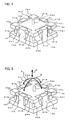
- a microscopic positioning device having 2-axis coarse adjustment positioning means illustrated in FIG. 6 is fixed onto a rotating table 40.
- Fixed onto the movable member 20 of the microscopic positioning device is a tool holder 41, and a tool 42 is mounted on the tool holder 41.
- FIG. 8 shows the fifth embodiment in FIG. 7 viewed from above.
- the coarse adjustment is first made by using the micrometers 31 and 32 to reduce an error to micron order.
- the piezoelectric elements P11 through P22 are driven to compensate the position of the blade edge till the error is reduced to nano order.
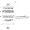
- the blade edge of the tool 42 is observed by microscope, and the deviation of the position from the rotational center point CP of the rotating table 40 is measured in the micron order (Step S1). Subsequently, the position of the tool blade edge is compensated by making the coarse adjustment for shifting the base member 10 in the X-axis and Y-axis directions using the micrometers 31 and 32. The coarse adjustment reduces the error between the blade edge position of the tool 42 and the rotational center point CP of the rotating table 40 to micron order (Step S2). Thereafter, the test machining is performed to measure a machining error in the nano-order (Step S3).
- Step S4 A judgement is made as to whether the machining error as a result of the measurement is within an allowable range (Step S4). If the error is not within the allowable range, the piezoelectric elements P11 through P22 are driven to compensate the position and orientation of the blade tip end of the tool 42 by carrying out fine adjustment (Step S5). The test machining is performed again to measure the machining error in the nano-order, and to judge whether the machining error is within the allowable range. Thereafter, Steps S3, S4 and S5 are repeatedly performed, and when it is judged that the machining error enters the allowable range, a real machining is performed (Step S6).
- the above steps make it possible to make the blade edge coincide with the rotational center point of the rotating table 40 in the nano-order.
- the device can be used for compensating the tool position and the tool orientation for general purpose because of the capability of performing the precision positioning of six axes.
- the same movable member 20 is driven in the X-axis and Y-axis directions. It is possible, however, that the movable member is constructed in double layer to have a configuration comprising a first movable member driven by a driving unit composed of two piezoelectric elements which drive the first movable member in the X- (or Y-) axis direction with respect to the base member 10 and a second movable member driven by a driving unit composed of two piezoelectric elements which drive the second movable member in the Y- (or X-) axis direction orthogonal to the shifting direction of the first movable member with respect to the first movable member.
- guide means for guiding the shift of the first and second movable members there may be provided guide means for guiding the shift of the first and second movable members. At least in case that a driving unit is provided to each movable member, the guide means for guiding the shift of the first and second movable members are provided to the respective movable members.
- the microscopic positioning device of the present invention it is possible to perform the positioning with nano-order resolution with high machine rigidity. Furthermore, using the six-axis microscopic positioning device enables compensation of the position and orientation of the tool blade edge in the nano-order.
Landscapes
- Control Of Position Or Direction (AREA)
- General Electrical Machinery Utilizing Piezoelectricity, Electrostriction Or Magnetostriction (AREA)
- Automatic Control Of Machine Tools (AREA)
Abstract
Description
At the same time, voltage is so applied that the piezoelectric elements P11 and P16, which are located so that respective axes are parallel to the Y-axis direction, have respective displacement amounts satisfying an equation, a11 = a16 = 0, and that the piezoelectric elements P12 and P15 have those satisfying an equation, a12 = a15 = a. By doing so, the
Claims (6)
- A microscopic positioning device comprising:a base member having first and second abutting faces;a movable member having first and second abutting faces; andat least one driving unit for driving said movable member to be positioned with respect to said base member, including a first piezoelectric element and a second piezoelectric element arranged along a straight line on which expanding/shrinking directions thereof are aligned, one end and the other end of said first piezoelectric element in the expanding/shrinking direction being fixed to the first abutting faces of said base member and said movable member, respectively, and one end of said second piezoelectric element in the expanding/shrinking direction being fixed to one of the second abutting faces of said base member and said movable member, and the other end of said second piezoelectric element being confronting the other of the second abutting faces of said base member and said movable member with a gap in between in unenergized states of said first and second piezoelectric elements.
- A microscopic positioning device according to claim 1, wherein one or more driving units are provided for one of perpendicular directions such that the straight lines on which the expanding/shrinking directions of the piezoelectric elements of respective driving units are aligned extend perpendicular to each other, so that said movable member is driven with respect to said base member in the perpendicular directions.
- A microscopic positioning device according to claim 1, wherein four driving units are provided along four sides of a rectangle to drive and position a single movable member with respect to a single base member.
- A microscopic positioning device according to claim 3, further comprising an additional piezoelectric element disposed at each of four comers of the rectangle, wherein an expanding/shrinking direction of the additional piezoelectric element extends in a direction perpendicular to a plane of the rectangle, and one end and the other end of said additional piezoelectric element are fixed to said base member and said movable member, respectively.
- A microscopic positioning device according to claim 1, further comprising a micrometer for performing a coarse positioning of said base member along a coarse adjustment axis in the same direction as the expanding/shrinking directions of the piezoelectric elements of at least one of said driving units.
- A method of compensating a position and/or an orientation of a blade edge of a tool in a nano-order using a microscopic positioning device comprising:a base member having first and second abutting faces;a movable member having first and second abutting faces;at least one driving unit for driving said movable member to be positioned with respect to said base member, including a first piezoelectric element and a second piezoelectric element arranged along a straight line on which expanding/shrinking directions thereof are aligned, one end and the other end of said first piezoelectric element in the expanding/shrinking direction being fixed to the first abutting faces of said base member and said movable member, respectively, and one end of said second piezoelectric element in the expanding/shrinking direction being fixed to one of the second abutting faces of said base member and said movable member, and the other end of said second piezoelectric element being confronting the other of the second abutting faces of said base member and said movable member with a predetermined gap in between in unenergized states of said first and second piezoelectric elements.
Applications Claiming Priority (2)
| Application Number | Priority Date | Filing Date | Title |
|---|---|---|---|
| JP2003160308A JP3792675B2 (en) | 2003-06-05 | 2003-06-05 | Fine positioning apparatus and tool correction method |
| JP2003160308 | 2003-06-05 |
Publications (3)
| Publication Number | Publication Date |
|---|---|
| EP1484804A2 true EP1484804A2 (en) | 2004-12-08 |
| EP1484804A3 EP1484804A3 (en) | 2005-11-16 |
| EP1484804B1 EP1484804B1 (en) | 2007-08-29 |
Family
ID=33157193
Family Applications (1)
| Application Number | Title | Priority Date | Filing Date |
|---|---|---|---|
| EP04253088A Expired - Lifetime EP1484804B1 (en) | 2003-06-05 | 2004-05-26 | Microscopic positioning device and tool position/orientation compensating method |
Country Status (5)
| Country | Link |
|---|---|
| US (1) | US6920696B2 (en) |
| EP (1) | EP1484804B1 (en) |
| JP (1) | JP3792675B2 (en) |
| CN (1) | CN1293988C (en) |
| DE (1) | DE602004008534T2 (en) |
Cited By (2)
| Publication number | Priority date | Publication date | Assignee | Title |
|---|---|---|---|---|
| KR101358363B1 (en) | 2012-03-30 | 2014-02-07 | 조선대학교산학협력단 | Apparatus for compensating error of work machine spindle |
| CN105531057A (en) * | 2013-05-08 | 2016-04-27 | 慕尼黑科技大学 | Device for generating a rotary ultrasonic vibration on a tool |
Families Citing this family (20)
| Publication number | Priority date | Publication date | Assignee | Title |
|---|---|---|---|---|
| AU2003206380A1 (en) * | 2002-01-03 | 2003-07-24 | Board Of Trustees Of The University Of Arkansas | Apparatus and method for nanoscale and microscale mechanical machining and processing |
| AU2003901914A0 (en) * | 2003-04-22 | 2003-05-08 | Quantum Precision Instruments Pty Ltd | Quantum tunnelling transducer device |
| EP1519144A1 (en) * | 2003-09-29 | 2005-03-30 | Nederlandse Organisatie voor toegepast-natuurwetenschappelijk onderzoek TNO | Free-form optical surface measuring apparatus and method |
| KR100568206B1 (en) * | 2004-02-13 | 2006-04-05 | 삼성전자주식회사 | Stage device |
| US7272411B2 (en) * | 2005-01-07 | 2007-09-18 | Research In Motion Limited | Dual-mode keypad for a mobile device |
| US7331714B2 (en) * | 2005-09-29 | 2008-02-19 | Uchicago Argonne, Llc | Optomechanical structure for a multifunctional hard x-ray nanoprobe instrument |
| US20090057520A1 (en) * | 2007-09-05 | 2009-03-05 | Makoto Tada | Displacement Platform with a Precision Plane |
| US7607234B2 (en) * | 2007-09-05 | 2009-10-27 | Hiwin Mikrosystem Corp. | Positive load alignment mechanism |
| RU2605816C9 (en) * | 2008-10-09 | 2017-05-10 | Ньюкасл Инновейшн Лимитед | Positioning system and method |
| KR100979539B1 (en) * | 2010-01-29 | 2010-09-02 | 아주대학교산학협력단 | In-plane 3 degree-of-freedom positioning stage |
| KR101110420B1 (en) * | 2011-02-16 | 2012-02-24 | 한국기계연구원 | Substrate alignment module and lithographic apparatus having the same |
| KR101617284B1 (en) | 2014-03-26 | 2016-05-02 | 한국전기연구원 | a level control device using Piezoelectric actuator |
| KR101648805B1 (en) * | 2014-07-30 | 2016-08-17 | 한국과학기술원 | Piezoelectric stepping motor |
| WO2018153921A1 (en) * | 2017-02-24 | 2018-08-30 | Marposs Societa' Per Azioni | Bidirectional measuring head for dimensional and/or geometric checking of a mechanical piece |
| CN106881618B (en) * | 2017-04-05 | 2023-11-28 | 广州铁路职业技术学院 | A two-axis linkage fast tool servo device |
| US10535495B2 (en) * | 2018-04-10 | 2020-01-14 | Bae Systems Information And Electronic Systems Integration Inc. | Sample manipulation for nondestructive sample imaging |
| US11340179B2 (en) | 2019-10-21 | 2022-05-24 | Bae Systems Information And Electronic System Integration Inc. | Nanofabricated structures for sub-beam resolution and spectral enhancement in tomographic imaging |
| JP6781391B1 (en) | 2019-11-22 | 2020-11-04 | 株式会社東京精密 | Surface shape measuring machine and surface shape measuring method |
| EP3889543B1 (en) * | 2020-04-01 | 2023-06-07 | Leica Geosystems AG | Six-dof measurement accessory module for determining 3d coordinates of points of an object surface to be measured |
| US11365960B1 (en) * | 2022-01-21 | 2022-06-21 | Guangdong University Of Technology | XY macro-micro motion stage and control method thereof based on end feedback |
Family Cites Families (18)
| Publication number | Priority date | Publication date | Assignee | Title |
|---|---|---|---|---|
| US4575942A (en) * | 1982-10-18 | 1986-03-18 | Hitachi, Ltd. | Ultra-precision two-dimensional moving apparatus |
| US4520570A (en) * | 1983-12-30 | 1985-06-04 | International Business Machines Corporation | Piezoelectric x-y-positioner |
| JPS60228003A (en) * | 1984-04-26 | 1985-11-13 | Mazda Motor Corp | Moving device for tool stand |
| DE3788773T2 (en) * | 1986-09-09 | 1994-08-04 | Hitachi Construction Machinery | Device for fine adjustment and device for controlling these adjustments. |
| US4798989A (en) * | 1986-09-26 | 1989-01-17 | Research Development Corporation | Scanning tunneling microscope installed in electron microscope |
| JP2566415B2 (en) * | 1987-06-25 | 1996-12-25 | 光洋精工株式会社 | Precision positioning device |
| JPH064210B2 (en) * | 1987-10-20 | 1994-01-19 | 日本電気株式会社 | Positioning mechanism |
| US5280677A (en) * | 1990-05-17 | 1994-01-25 | Canon Kabushiki Kaisha | Positioning mechanism |
| CA2060674C (en) * | 1991-02-08 | 1996-10-01 | Masahiro Tagawa | Driving apparatus and a recording and/or reproducing apparatus using the same |
| US5351412A (en) * | 1991-06-11 | 1994-10-04 | International Business Machines Corporation | Micro positioning device |
| JP2789166B2 (en) | 1994-05-11 | 1998-08-20 | 畑村 洋太郎 | Grinding method |
| JPH1019906A (en) * | 1996-07-08 | 1998-01-23 | Nikon Corp | Probe driving device and scanning probe microscope using the same |
| JPH10118874A (en) * | 1996-10-25 | 1998-05-12 | Okuma Mach Works Ltd | Minute interval driving mechanism |
| US6230070B1 (en) * | 1997-07-23 | 2001-05-08 | Fuji Seiki Co., Ltd. | Work position adjusting apparatus and adjusting method |
| US6408526B1 (en) * | 1999-04-12 | 2002-06-25 | The Regents Of The University Of California | Ultra-precision positioning assembly |
| US6467761B1 (en) * | 1999-06-21 | 2002-10-22 | The United States Of America As Represented By The Secretary Of Commerce | Positioning stage |
| US6513250B2 (en) * | 2000-07-14 | 2003-02-04 | Rensselaer Polytechnic Institute | Micro positioning device with shared actuators |
| JP2004223647A (en) * | 2003-01-22 | 2004-08-12 | Nsk Ltd | Positioning device |
-
2003
- 2003-06-05 JP JP2003160308A patent/JP3792675B2/en not_active Expired - Fee Related
-
2004
- 2004-05-26 EP EP04253088A patent/EP1484804B1/en not_active Expired - Lifetime
- 2004-05-26 US US10/853,140 patent/US6920696B2/en not_active Expired - Fee Related
- 2004-05-26 DE DE602004008534T patent/DE602004008534T2/en not_active Expired - Fee Related
- 2004-06-04 CN CNB2004100462505A patent/CN1293988C/en not_active Expired - Fee Related
Cited By (2)
| Publication number | Priority date | Publication date | Assignee | Title |
|---|---|---|---|---|
| KR101358363B1 (en) | 2012-03-30 | 2014-02-07 | 조선대학교산학협력단 | Apparatus for compensating error of work machine spindle |
| CN105531057A (en) * | 2013-05-08 | 2016-04-27 | 慕尼黑科技大学 | Device for generating a rotary ultrasonic vibration on a tool |
Also Published As
| Publication number | Publication date |
|---|---|
| CN1293988C (en) | 2007-01-10 |
| DE602004008534T2 (en) | 2008-05-21 |
| JP2004358611A (en) | 2004-12-24 |
| EP1484804A3 (en) | 2005-11-16 |
| DE602004008534D1 (en) | 2007-10-11 |
| US20040244208A1 (en) | 2004-12-09 |
| JP3792675B2 (en) | 2006-07-05 |
| EP1484804B1 (en) | 2007-08-29 |
| US6920696B2 (en) | 2005-07-26 |
| CN1572418A (en) | 2005-02-02 |
Similar Documents
| Publication | Publication Date | Title |
|---|---|---|
| EP1484804B1 (en) | Microscopic positioning device and tool position/orientation compensating method | |
| US6467761B1 (en) | Positioning stage | |
| US6484602B1 (en) | Six-degree of freedom micro-positioner | |
| Shinno et al. | XY-θ nano-positioning table system for a mother machine | |
| US6230070B1 (en) | Work position adjusting apparatus and adjusting method | |
| US7243571B2 (en) | Ultra-precision positioning system | |
| KR20060013219A (en) | Ultra Precision Positioning System | |
| JP2009076521A (en) | Precision fine positioning apparatus and fine positioning stage, exposure apparatus and inspection apparatus provided with the same | |
| JPH10138075A (en) | Work posture adjustment device, adjustment tool and adjustment method | |
| US6860020B2 (en) | Ultra-precision feeding apparatus | |
| US20030051331A1 (en) | Positioning stage actuation | |
| US20030029012A1 (en) | Positioning stage | |
| US7504794B2 (en) | Planar motor | |
| US8941814B2 (en) | Multiple-blade holding devices | |
| JPH0386434A (en) | Precision stage device | |
| JPH01188241A (en) | Shift guiding device | |
| JPH1123752A (en) | Travel guide device | |
| JPS61243511A (en) | Fine positioning device | |
| JP2001242937A (en) | Stage equipment | |
| KR100434975B1 (en) | Positioning System of Nano-Meter Stage and Method Thereof | |
| JPH05335199A (en) | Fine positioning device | |
| JP4925223B2 (en) | Inspection device | |
| JPH071451B2 (en) | Displacement control device for fine positioning device | |
| JP2952458B2 (en) | XY stage device | |
| JPH07104723B2 (en) | Fine positioning device |
Legal Events
| Date | Code | Title | Description |
|---|---|---|---|
| PUAI | Public reference made under article 153(3) epc to a published international application that has entered the european phase |
Free format text: ORIGINAL CODE: 0009012 |
|
| AK | Designated contracting states |
Kind code of ref document: A2 Designated state(s): AT BE BG CH CY CZ DE DK EE ES FI FR GB GR HU IE IT LI LU MC NL PL PT RO SE SI SK TR |
|
| AX | Request for extension of the european patent |
Extension state: AL HR LT LV MK |
|
| PUAL | Search report despatched |
Free format text: ORIGINAL CODE: 0009013 |
|
| AK | Designated contracting states |
Kind code of ref document: A3 Designated state(s): AT BE BG CH CY CZ DE DK EE ES FI FR GB GR HU IE IT LI LU MC NL PL PT RO SE SI SK TR |
|
| AX | Request for extension of the european patent |
Extension state: AL HR LT LV MK |
|
| 17P | Request for examination filed |
Effective date: 20060322 |
|
| AKX | Designation fees paid |
Designated state(s): DE |
|
| GRAP | Despatch of communication of intention to grant a patent |
Free format text: ORIGINAL CODE: EPIDOSNIGR1 |
|
| GRAS | Grant fee paid |
Free format text: ORIGINAL CODE: EPIDOSNIGR3 |
|
| GRAA | (expected) grant |
Free format text: ORIGINAL CODE: 0009210 |
|
| AK | Designated contracting states |
Kind code of ref document: B1 Designated state(s): DE |
|
| RIN1 | Information on inventor provided before grant (corrected) |
Inventor name: SAKAIDA, YASUHIRO,ROOM 8-209 Inventor name: EBIHARA, KENZO,FANUC Inventor name: SAWADA, KIYOSHI |
|
| REF | Corresponds to: |
Ref document number: 602004008534 Country of ref document: DE Date of ref document: 20071011 Kind code of ref document: P |
|
| PLBE | No opposition filed within time limit |
Free format text: ORIGINAL CODE: 0009261 |
|
| STAA | Information on the status of an ep patent application or granted ep patent |
Free format text: STATUS: NO OPPOSITION FILED WITHIN TIME LIMIT |
|
| PGFP | Annual fee paid to national office [announced via postgrant information from national office to epo] |
Ref country code: DE Payment date: 20080606 Year of fee payment: 5 |
|
| 26N | No opposition filed |
Effective date: 20080530 |
|
| PG25 | Lapsed in a contracting state [announced via postgrant information from national office to epo] |
Ref country code: DE Free format text: LAPSE BECAUSE OF NON-PAYMENT OF DUE FEES Effective date: 20091201 |