EP1484758A2 - Optical information recording method - Google Patents
Optical information recording method Download PDFInfo
- Publication number
- EP1484758A2 EP1484758A2 EP04253175A EP04253175A EP1484758A2 EP 1484758 A2 EP1484758 A2 EP 1484758A2 EP 04253175 A EP04253175 A EP 04253175A EP 04253175 A EP04253175 A EP 04253175A EP 1484758 A2 EP1484758 A2 EP 1484758A2
- Authority
- EP
- European Patent Office
- Prior art keywords
- optical information
- dye
- information recording
- substrate
- recording
- Prior art date
- Legal status (The legal status is an assumption and is not a legal conclusion. Google has not performed a legal analysis and makes no representation as to the accuracy of the status listed.)
- Withdrawn
Links
Classifications
-
- G—PHYSICS
- G11—INFORMATION STORAGE
- G11B—INFORMATION STORAGE BASED ON RELATIVE MOVEMENT BETWEEN RECORD CARRIER AND TRANSDUCER
- G11B7/00—Recording or reproducing by optical means, e.g. recording using a thermal beam of optical radiation by modifying optical properties or the physical structure, reproducing using an optical beam at lower power by sensing optical properties; Record carriers therefor
- G11B7/24—Record carriers characterised by shape, structure or physical properties, or by the selection of the material
- G11B7/241—Record carriers characterised by shape, structure or physical properties, or by the selection of the material characterised by the selection of the material
- G11B7/242—Record carriers characterised by shape, structure or physical properties, or by the selection of the material characterised by the selection of the material of recording layers
- G11B7/244—Record carriers characterised by shape, structure or physical properties, or by the selection of the material characterised by the selection of the material of recording layers comprising organic materials only
- G11B7/246—Record carriers characterised by shape, structure or physical properties, or by the selection of the material characterised by the selection of the material of recording layers comprising organic materials only containing dyes
-
- G—PHYSICS
- G11—INFORMATION STORAGE
- G11B—INFORMATION STORAGE BASED ON RELATIVE MOVEMENT BETWEEN RECORD CARRIER AND TRANSDUCER
- G11B7/00—Recording or reproducing by optical means, e.g. recording using a thermal beam of optical radiation by modifying optical properties or the physical structure, reproducing using an optical beam at lower power by sensing optical properties; Record carriers therefor
- G11B7/24—Record carriers characterised by shape, structure or physical properties, or by the selection of the material
- G11B7/241—Record carriers characterised by shape, structure or physical properties, or by the selection of the material characterised by the selection of the material
- G11B7/252—Record carriers characterised by shape, structure or physical properties, or by the selection of the material characterised by the selection of the material of layers other than recording layers
- G11B7/257—Record carriers characterised by shape, structure or physical properties, or by the selection of the material characterised by the selection of the material of layers other than recording layers of layers having properties involved in recording or reproduction, e.g. optical interference layers or sensitising layers or dielectric layers, which are protecting the recording layers
- G11B2007/25705—Record carriers characterised by shape, structure or physical properties, or by the selection of the material characterised by the selection of the material of layers other than recording layers of layers having properties involved in recording or reproduction, e.g. optical interference layers or sensitising layers or dielectric layers, which are protecting the recording layers consisting essentially of inorganic materials
- G11B2007/2571—Record carriers characterised by shape, structure or physical properties, or by the selection of the material characterised by the selection of the material of layers other than recording layers of layers having properties involved in recording or reproduction, e.g. optical interference layers or sensitising layers or dielectric layers, which are protecting the recording layers consisting essentially of inorganic materials containing group 14 elements except carbon (Si, Ge, Sn, Pb)
-
- G—PHYSICS
- G11—INFORMATION STORAGE
- G11B—INFORMATION STORAGE BASED ON RELATIVE MOVEMENT BETWEEN RECORD CARRIER AND TRANSDUCER
- G11B7/00—Recording or reproducing by optical means, e.g. recording using a thermal beam of optical radiation by modifying optical properties or the physical structure, reproducing using an optical beam at lower power by sensing optical properties; Record carriers therefor
- G11B7/004—Recording, reproducing or erasing methods; Read, write or erase circuits therefor
- G11B7/0045—Recording
- G11B7/00455—Recording involving reflectivity, absorption or colour changes
-
- G—PHYSICS
- G11—INFORMATION STORAGE
- G11B—INFORMATION STORAGE BASED ON RELATIVE MOVEMENT BETWEEN RECORD CARRIER AND TRANSDUCER
- G11B7/00—Recording or reproducing by optical means, e.g. recording using a thermal beam of optical radiation by modifying optical properties or the physical structure, reproducing using an optical beam at lower power by sensing optical properties; Record carriers therefor
- G11B7/24—Record carriers characterised by shape, structure or physical properties, or by the selection of the material
- G11B7/241—Record carriers characterised by shape, structure or physical properties, or by the selection of the material characterised by the selection of the material
- G11B7/242—Record carriers characterised by shape, structure or physical properties, or by the selection of the material characterised by the selection of the material of recording layers
- G11B7/244—Record carriers characterised by shape, structure or physical properties, or by the selection of the material characterised by the selection of the material of recording layers comprising organic materials only
- G11B7/245—Record carriers characterised by shape, structure or physical properties, or by the selection of the material characterised by the selection of the material of recording layers comprising organic materials only containing a polymeric component
-
- G—PHYSICS
- G11—INFORMATION STORAGE
- G11B—INFORMATION STORAGE BASED ON RELATIVE MOVEMENT BETWEEN RECORD CARRIER AND TRANSDUCER
- G11B7/00—Recording or reproducing by optical means, e.g. recording using a thermal beam of optical radiation by modifying optical properties or the physical structure, reproducing using an optical beam at lower power by sensing optical properties; Record carriers therefor
- G11B7/24—Record carriers characterised by shape, structure or physical properties, or by the selection of the material
- G11B7/241—Record carriers characterised by shape, structure or physical properties, or by the selection of the material characterised by the selection of the material
- G11B7/242—Record carriers characterised by shape, structure or physical properties, or by the selection of the material characterised by the selection of the material of recording layers
- G11B7/244—Record carriers characterised by shape, structure or physical properties, or by the selection of the material characterised by the selection of the material of recording layers comprising organic materials only
- G11B7/246—Record carriers characterised by shape, structure or physical properties, or by the selection of the material characterised by the selection of the material of recording layers comprising organic materials only containing dyes
- G11B7/2463—Record carriers characterised by shape, structure or physical properties, or by the selection of the material characterised by the selection of the material of recording layers comprising organic materials only containing dyes azulene
-
- G—PHYSICS
- G11—INFORMATION STORAGE
- G11B—INFORMATION STORAGE BASED ON RELATIVE MOVEMENT BETWEEN RECORD CARRIER AND TRANSDUCER
- G11B7/00—Recording or reproducing by optical means, e.g. recording using a thermal beam of optical radiation by modifying optical properties or the physical structure, reproducing using an optical beam at lower power by sensing optical properties; Record carriers therefor
- G11B7/24—Record carriers characterised by shape, structure or physical properties, or by the selection of the material
- G11B7/241—Record carriers characterised by shape, structure or physical properties, or by the selection of the material characterised by the selection of the material
- G11B7/242—Record carriers characterised by shape, structure or physical properties, or by the selection of the material characterised by the selection of the material of recording layers
- G11B7/244—Record carriers characterised by shape, structure or physical properties, or by the selection of the material characterised by the selection of the material of recording layers comprising organic materials only
- G11B7/246—Record carriers characterised by shape, structure or physical properties, or by the selection of the material characterised by the selection of the material of recording layers comprising organic materials only containing dyes
- G11B7/2467—Record carriers characterised by shape, structure or physical properties, or by the selection of the material characterised by the selection of the material of recording layers comprising organic materials only containing dyes azo-dyes
-
- G—PHYSICS
- G11—INFORMATION STORAGE
- G11B—INFORMATION STORAGE BASED ON RELATIVE MOVEMENT BETWEEN RECORD CARRIER AND TRANSDUCER
- G11B7/00—Recording or reproducing by optical means, e.g. recording using a thermal beam of optical radiation by modifying optical properties or the physical structure, reproducing using an optical beam at lower power by sensing optical properties; Record carriers therefor
- G11B7/24—Record carriers characterised by shape, structure or physical properties, or by the selection of the material
- G11B7/241—Record carriers characterised by shape, structure or physical properties, or by the selection of the material characterised by the selection of the material
- G11B7/242—Record carriers characterised by shape, structure or physical properties, or by the selection of the material characterised by the selection of the material of recording layers
- G11B7/244—Record carriers characterised by shape, structure or physical properties, or by the selection of the material characterised by the selection of the material of recording layers comprising organic materials only
- G11B7/246—Record carriers characterised by shape, structure or physical properties, or by the selection of the material characterised by the selection of the material of recording layers comprising organic materials only containing dyes
- G11B7/247—Record carriers characterised by shape, structure or physical properties, or by the selection of the material characterised by the selection of the material of recording layers comprising organic materials only containing dyes methine or polymethine dyes
- G11B7/2472—Record carriers characterised by shape, structure or physical properties, or by the selection of the material characterised by the selection of the material of recording layers comprising organic materials only containing dyes methine or polymethine dyes cyanine
-
- G—PHYSICS
- G11—INFORMATION STORAGE
- G11B—INFORMATION STORAGE BASED ON RELATIVE MOVEMENT BETWEEN RECORD CARRIER AND TRANSDUCER
- G11B7/00—Recording or reproducing by optical means, e.g. recording using a thermal beam of optical radiation by modifying optical properties or the physical structure, reproducing using an optical beam at lower power by sensing optical properties; Record carriers therefor
- G11B7/24—Record carriers characterised by shape, structure or physical properties, or by the selection of the material
- G11B7/241—Record carriers characterised by shape, structure or physical properties, or by the selection of the material characterised by the selection of the material
- G11B7/242—Record carriers characterised by shape, structure or physical properties, or by the selection of the material characterised by the selection of the material of recording layers
- G11B7/244—Record carriers characterised by shape, structure or physical properties, or by the selection of the material characterised by the selection of the material of recording layers comprising organic materials only
- G11B7/246—Record carriers characterised by shape, structure or physical properties, or by the selection of the material characterised by the selection of the material of recording layers comprising organic materials only containing dyes
- G11B7/247—Record carriers characterised by shape, structure or physical properties, or by the selection of the material characterised by the selection of the material of recording layers comprising organic materials only containing dyes methine or polymethine dyes
- G11B7/2475—Record carriers characterised by shape, structure or physical properties, or by the selection of the material characterised by the selection of the material of recording layers comprising organic materials only containing dyes methine or polymethine dyes merocyanine
-
- G—PHYSICS
- G11—INFORMATION STORAGE
- G11B—INFORMATION STORAGE BASED ON RELATIVE MOVEMENT BETWEEN RECORD CARRIER AND TRANSDUCER
- G11B7/00—Recording or reproducing by optical means, e.g. recording using a thermal beam of optical radiation by modifying optical properties or the physical structure, reproducing using an optical beam at lower power by sensing optical properties; Record carriers therefor
- G11B7/24—Record carriers characterised by shape, structure or physical properties, or by the selection of the material
- G11B7/241—Record carriers characterised by shape, structure or physical properties, or by the selection of the material characterised by the selection of the material
- G11B7/242—Record carriers characterised by shape, structure or physical properties, or by the selection of the material characterised by the selection of the material of recording layers
- G11B7/244—Record carriers characterised by shape, structure or physical properties, or by the selection of the material characterised by the selection of the material of recording layers comprising organic materials only
- G11B7/246—Record carriers characterised by shape, structure or physical properties, or by the selection of the material characterised by the selection of the material of recording layers comprising organic materials only containing dyes
- G11B7/247—Record carriers characterised by shape, structure or physical properties, or by the selection of the material characterised by the selection of the material of recording layers comprising organic materials only containing dyes methine or polymethine dyes
- G11B7/2478—Record carriers characterised by shape, structure or physical properties, or by the selection of the material characterised by the selection of the material of recording layers comprising organic materials only containing dyes methine or polymethine dyes oxonol
-
- G—PHYSICS
- G11—INFORMATION STORAGE
- G11B—INFORMATION STORAGE BASED ON RELATIVE MOVEMENT BETWEEN RECORD CARRIER AND TRANSDUCER
- G11B7/00—Recording or reproducing by optical means, e.g. recording using a thermal beam of optical radiation by modifying optical properties or the physical structure, reproducing using an optical beam at lower power by sensing optical properties; Record carriers therefor
- G11B7/24—Record carriers characterised by shape, structure or physical properties, or by the selection of the material
- G11B7/241—Record carriers characterised by shape, structure or physical properties, or by the selection of the material characterised by the selection of the material
- G11B7/242—Record carriers characterised by shape, structure or physical properties, or by the selection of the material characterised by the selection of the material of recording layers
- G11B7/244—Record carriers characterised by shape, structure or physical properties, or by the selection of the material characterised by the selection of the material of recording layers comprising organic materials only
- G11B7/246—Record carriers characterised by shape, structure or physical properties, or by the selection of the material characterised by the selection of the material of recording layers comprising organic materials only containing dyes
- G11B7/248—Record carriers characterised by shape, structure or physical properties, or by the selection of the material characterised by the selection of the material of recording layers comprising organic materials only containing dyes porphines; azaporphines, e.g. phthalocyanines
-
- G—PHYSICS
- G11—INFORMATION STORAGE
- G11B—INFORMATION STORAGE BASED ON RELATIVE MOVEMENT BETWEEN RECORD CARRIER AND TRANSDUCER
- G11B7/00—Recording or reproducing by optical means, e.g. recording using a thermal beam of optical radiation by modifying optical properties or the physical structure, reproducing using an optical beam at lower power by sensing optical properties; Record carriers therefor
- G11B7/24—Record carriers characterised by shape, structure or physical properties, or by the selection of the material
- G11B7/241—Record carriers characterised by shape, structure or physical properties, or by the selection of the material characterised by the selection of the material
- G11B7/242—Record carriers characterised by shape, structure or physical properties, or by the selection of the material characterised by the selection of the material of recording layers
- G11B7/244—Record carriers characterised by shape, structure or physical properties, or by the selection of the material characterised by the selection of the material of recording layers comprising organic materials only
- G11B7/249—Record carriers characterised by shape, structure or physical properties, or by the selection of the material characterised by the selection of the material of recording layers comprising organic materials only containing organometallic compounds
-
- G—PHYSICS
- G11—INFORMATION STORAGE
- G11B—INFORMATION STORAGE BASED ON RELATIVE MOVEMENT BETWEEN RECORD CARRIER AND TRANSDUCER
- G11B7/00—Recording or reproducing by optical means, e.g. recording using a thermal beam of optical radiation by modifying optical properties or the physical structure, reproducing using an optical beam at lower power by sensing optical properties; Record carriers therefor
- G11B7/24—Record carriers characterised by shape, structure or physical properties, or by the selection of the material
- G11B7/241—Record carriers characterised by shape, structure or physical properties, or by the selection of the material characterised by the selection of the material
- G11B7/252—Record carriers characterised by shape, structure or physical properties, or by the selection of the material characterised by the selection of the material of layers other than recording layers
- G11B7/253—Record carriers characterised by shape, structure or physical properties, or by the selection of the material characterised by the selection of the material of layers other than recording layers of substrates
- G11B7/2531—Record carriers characterised by shape, structure or physical properties, or by the selection of the material characterised by the selection of the material of layers other than recording layers of substrates comprising glass
-
- G—PHYSICS
- G11—INFORMATION STORAGE
- G11B—INFORMATION STORAGE BASED ON RELATIVE MOVEMENT BETWEEN RECORD CARRIER AND TRANSDUCER
- G11B7/00—Recording or reproducing by optical means, e.g. recording using a thermal beam of optical radiation by modifying optical properties or the physical structure, reproducing using an optical beam at lower power by sensing optical properties; Record carriers therefor
- G11B7/24—Record carriers characterised by shape, structure or physical properties, or by the selection of the material
- G11B7/241—Record carriers characterised by shape, structure or physical properties, or by the selection of the material characterised by the selection of the material
- G11B7/252—Record carriers characterised by shape, structure or physical properties, or by the selection of the material characterised by the selection of the material of layers other than recording layers
- G11B7/253—Record carriers characterised by shape, structure or physical properties, or by the selection of the material characterised by the selection of the material of layers other than recording layers of substrates
- G11B7/2532—Record carriers characterised by shape, structure or physical properties, or by the selection of the material characterised by the selection of the material of layers other than recording layers of substrates comprising metals
-
- G—PHYSICS
- G11—INFORMATION STORAGE
- G11B—INFORMATION STORAGE BASED ON RELATIVE MOVEMENT BETWEEN RECORD CARRIER AND TRANSDUCER
- G11B7/00—Recording or reproducing by optical means, e.g. recording using a thermal beam of optical radiation by modifying optical properties or the physical structure, reproducing using an optical beam at lower power by sensing optical properties; Record carriers therefor
- G11B7/24—Record carriers characterised by shape, structure or physical properties, or by the selection of the material
- G11B7/241—Record carriers characterised by shape, structure or physical properties, or by the selection of the material characterised by the selection of the material
- G11B7/252—Record carriers characterised by shape, structure or physical properties, or by the selection of the material characterised by the selection of the material of layers other than recording layers
- G11B7/253—Record carriers characterised by shape, structure or physical properties, or by the selection of the material characterised by the selection of the material of layers other than recording layers of substrates
- G11B7/2533—Record carriers characterised by shape, structure or physical properties, or by the selection of the material characterised by the selection of the material of layers other than recording layers of substrates comprising resins
-
- G—PHYSICS
- G11—INFORMATION STORAGE
- G11B—INFORMATION STORAGE BASED ON RELATIVE MOVEMENT BETWEEN RECORD CARRIER AND TRANSDUCER
- G11B7/00—Recording or reproducing by optical means, e.g. recording using a thermal beam of optical radiation by modifying optical properties or the physical structure, reproducing using an optical beam at lower power by sensing optical properties; Record carriers therefor
- G11B7/24—Record carriers characterised by shape, structure or physical properties, or by the selection of the material
- G11B7/241—Record carriers characterised by shape, structure or physical properties, or by the selection of the material characterised by the selection of the material
- G11B7/252—Record carriers characterised by shape, structure or physical properties, or by the selection of the material characterised by the selection of the material of layers other than recording layers
- G11B7/253—Record carriers characterised by shape, structure or physical properties, or by the selection of the material characterised by the selection of the material of layers other than recording layers of substrates
- G11B7/2533—Record carriers characterised by shape, structure or physical properties, or by the selection of the material characterised by the selection of the material of layers other than recording layers of substrates comprising resins
- G11B7/2534—Record carriers characterised by shape, structure or physical properties, or by the selection of the material characterised by the selection of the material of layers other than recording layers of substrates comprising resins polycarbonates [PC]
-
- G—PHYSICS
- G11—INFORMATION STORAGE
- G11B—INFORMATION STORAGE BASED ON RELATIVE MOVEMENT BETWEEN RECORD CARRIER AND TRANSDUCER
- G11B7/00—Recording or reproducing by optical means, e.g. recording using a thermal beam of optical radiation by modifying optical properties or the physical structure, reproducing using an optical beam at lower power by sensing optical properties; Record carriers therefor
- G11B7/24—Record carriers characterised by shape, structure or physical properties, or by the selection of the material
- G11B7/241—Record carriers characterised by shape, structure or physical properties, or by the selection of the material characterised by the selection of the material
- G11B7/252—Record carriers characterised by shape, structure or physical properties, or by the selection of the material characterised by the selection of the material of layers other than recording layers
- G11B7/253—Record carriers characterised by shape, structure or physical properties, or by the selection of the material characterised by the selection of the material of layers other than recording layers of substrates
- G11B7/2533—Record carriers characterised by shape, structure or physical properties, or by the selection of the material characterised by the selection of the material of layers other than recording layers of substrates comprising resins
- G11B7/2535—Record carriers characterised by shape, structure or physical properties, or by the selection of the material characterised by the selection of the material of layers other than recording layers of substrates comprising resins polyesters, e.g. PET, PETG or PEN
-
- G—PHYSICS
- G11—INFORMATION STORAGE
- G11B—INFORMATION STORAGE BASED ON RELATIVE MOVEMENT BETWEEN RECORD CARRIER AND TRANSDUCER
- G11B7/00—Recording or reproducing by optical means, e.g. recording using a thermal beam of optical radiation by modifying optical properties or the physical structure, reproducing using an optical beam at lower power by sensing optical properties; Record carriers therefor
- G11B7/24—Record carriers characterised by shape, structure or physical properties, or by the selection of the material
- G11B7/241—Record carriers characterised by shape, structure or physical properties, or by the selection of the material characterised by the selection of the material
- G11B7/252—Record carriers characterised by shape, structure or physical properties, or by the selection of the material characterised by the selection of the material of layers other than recording layers
- G11B7/254—Record carriers characterised by shape, structure or physical properties, or by the selection of the material characterised by the selection of the material of layers other than recording layers of protective topcoat layers
- G11B7/2542—Record carriers characterised by shape, structure or physical properties, or by the selection of the material characterised by the selection of the material of layers other than recording layers of protective topcoat layers consisting essentially of organic resins
-
- G—PHYSICS
- G11—INFORMATION STORAGE
- G11B—INFORMATION STORAGE BASED ON RELATIVE MOVEMENT BETWEEN RECORD CARRIER AND TRANSDUCER
- G11B7/00—Recording or reproducing by optical means, e.g. recording using a thermal beam of optical radiation by modifying optical properties or the physical structure, reproducing using an optical beam at lower power by sensing optical properties; Record carriers therefor
- G11B7/24—Record carriers characterised by shape, structure or physical properties, or by the selection of the material
- G11B7/241—Record carriers characterised by shape, structure or physical properties, or by the selection of the material characterised by the selection of the material
- G11B7/252—Record carriers characterised by shape, structure or physical properties, or by the selection of the material characterised by the selection of the material of layers other than recording layers
- G11B7/256—Record carriers characterised by shape, structure or physical properties, or by the selection of the material characterised by the selection of the material of layers other than recording layers of layers improving adhesion between layers
-
- G—PHYSICS
- G11—INFORMATION STORAGE
- G11B—INFORMATION STORAGE BASED ON RELATIVE MOVEMENT BETWEEN RECORD CARRIER AND TRANSDUCER
- G11B7/00—Recording or reproducing by optical means, e.g. recording using a thermal beam of optical radiation by modifying optical properties or the physical structure, reproducing using an optical beam at lower power by sensing optical properties; Record carriers therefor
- G11B7/24—Record carriers characterised by shape, structure or physical properties, or by the selection of the material
- G11B7/241—Record carriers characterised by shape, structure or physical properties, or by the selection of the material characterised by the selection of the material
- G11B7/252—Record carriers characterised by shape, structure or physical properties, or by the selection of the material characterised by the selection of the material of layers other than recording layers
- G11B7/257—Record carriers characterised by shape, structure or physical properties, or by the selection of the material characterised by the selection of the material of layers other than recording layers of layers having properties involved in recording or reproduction, e.g. optical interference layers or sensitising layers or dielectric layers, which are protecting the recording layers
- G11B7/2572—Record carriers characterised by shape, structure or physical properties, or by the selection of the material characterised by the selection of the material of layers other than recording layers of layers having properties involved in recording or reproduction, e.g. optical interference layers or sensitising layers or dielectric layers, which are protecting the recording layers consisting essentially of organic materials
- G11B7/2575—Record carriers characterised by shape, structure or physical properties, or by the selection of the material characterised by the selection of the material of layers other than recording layers of layers having properties involved in recording or reproduction, e.g. optical interference layers or sensitising layers or dielectric layers, which are protecting the recording layers consisting essentially of organic materials resins
-
- G—PHYSICS
- G11—INFORMATION STORAGE
- G11B—INFORMATION STORAGE BASED ON RELATIVE MOVEMENT BETWEEN RECORD CARRIER AND TRANSDUCER
- G11B7/00—Recording or reproducing by optical means, e.g. recording using a thermal beam of optical radiation by modifying optical properties or the physical structure, reproducing using an optical beam at lower power by sensing optical properties; Record carriers therefor
- G11B7/24—Record carriers characterised by shape, structure or physical properties, or by the selection of the material
- G11B7/241—Record carriers characterised by shape, structure or physical properties, or by the selection of the material characterised by the selection of the material
- G11B7/252—Record carriers characterised by shape, structure or physical properties, or by the selection of the material characterised by the selection of the material of layers other than recording layers
- G11B7/258—Record carriers characterised by shape, structure or physical properties, or by the selection of the material characterised by the selection of the material of layers other than recording layers of reflective layers
- G11B7/259—Record carriers characterised by shape, structure or physical properties, or by the selection of the material characterised by the selection of the material of layers other than recording layers of reflective layers based on silver
Definitions
- the present invention relates to a method for optically recording information to an optical information recording medium and particularly to a method for optically recording information at a linear velocity of at least 14 m/s.
- One conventionally known optical information recording medium is an optical disk on which information can be recorded with a laser beam only one time.
- Such an optical disk is also called a write-once CD (so called CD-R), whose typical structure includes a recording layer of organic dye, a light reflecting layer of metal such as gold, and a protective resin layer stacked in this order formed on a transparent substrate disk.
- CD-R write-once CD
- a near-infrared laser beam generally with a wavelength of about 780 nm
- an irradiated portion of the recording layer absorbs the beam and thus is locally heated and optical characteristics of the irradiated portion change physically or chemically (for example, pits are formed).
- a laser beam having the same wavelength as that used for recording irradiates the optical disk to detect a difference in reflectivity between a position of the recording layer with the changed optical characteristics (recorded portion) and a position of the recording layer with unchanged optical characteristics (unrecorded portion).
- DVD-R write-once Digital Versatile Disk
- the structure of such DVD-Rs includes: a transparent substrate disk having a guide groove (pre-groove) (0.74 to 0.8 ⁇ m) to be tracked by an irradiated laser beam (such a pre-groove is at least twice as more narrow as that of CD-R); a recording layer that includes a dye and is formed on the substrate; a light reflecting layer generally formed on the recording layer; and optionally a protective layer, wherein two disks each having the aforementioned layers or the disk having the aforementioned layers and a protective substrate disk with the same shape are bonded with an adhesive in such a manner that the recording layer is placed inside.
- Recording and playback are performed by irradiating a visible laser beam (generally with a wavelength in the range of from 630 nm to 680 nm) to the DVD-R.
- a visible laser beam generally with a wavelength in the range of from 630 nm to 680 nm
- the recording density of DVD-R can be made higher than that of CD-R.
- optimal recording power for an optical information recording medium is approximately proportional to the square root of recording speed.
- the optimal recording power at a recording speed of 4x is about twice as high as that at 1x.
- the energy applied for a short time increases, and thus the deformation of the recorded pit portion tends to increase.
- a greater deformation of the recorded pit can produce a higher degree of modulation so that the playback signal C/N can be higher.
- the signal leak to adjacent tracks increases, in other words, the crosstalk increases.
- a higher recording density means a shorter track pit and thus crosstalk has a large effect.
- JP-A Japanese Patent Application Laid-Open
- JP-A No. 10-188341 discloses an optical information recording medium in which a recording layer containing an organic dye as a main component has an exothermic peak of from -10 ⁇ V/mg to 10 ⁇ V/mg for the purpose of solving the problem of crosstalk.
- a recording layer containing an organic dye as a main component has an exothermic peak of from -10 ⁇ V/mg to 10 ⁇ V/mg for the purpose of solving the problem of crosstalk.
- formed pits are too large, which can have an adverse effect on the readout from adjacent tracks or the readout of the address information from the land portion.
- the present invention has been made in light of the above-mentioned problem. It is therefore an object of the invention to provide an optical information recording method by which LPP error rate can be kept low even when information is recorded at a linear velocity of at least 14 m/s.
- a first aspect of the invention is to provide an optical information recording method, which includes recording information at a linear velocity of at least 14 m/s to an optical information recording medium including a substrate and a dye-containing recording layer formed on the substrate.
- the dye has an endothermic peak when subjected to differential thermal analysis under a flow of nitrogen gas.
- the endothermic peak of the dye may be 10 ⁇ Vs/mg or more.
- the dye may also have an exothermic peak, and in such a dye, a total amount of endothermic heat is preferably larger than a total amount of exothermic heat.
- the optical information recording medium may have a track pitch of 0.8 ⁇ m or less and a minimum pit length of pits formed by recording may be 0.5 ⁇ m or less.
- a second aspect of the invention is to provide an optical information recording medium including a substrate and a dye-containing recording layer formed on the substrate.
- the dye has an endothermic peak when subjected to differential thermal analysis under a flow of nitrogen gas, and the optical information recording medium is for being recorded with information at a linear velocity of at least 14 m/s.
- the optical information recording method includes recording information at a linear velocity of at least 14 m/ s to an optical information recording medium that includes a substrate and a dye-containing recording layer formed on the substrate.
- the dye has an endothermic peak when subjected to differential thermal analysis under a flow of nitrogen gas.
- LPP error rate can be reduced, because the dye in the recording layer of the optical information recording medium has an endothermic peak.
- the optical information recording medium used in the method of the invention is a writable medium including a write-once optical information recording medium such as DVD-R.
- the optical information recording medium such as DVD-R includes two substrates (first and second substrates) bonded together, wherein a recording layer is formed at least on the first substrate, and preferably, any other layer such as a reflective layer and a protective layer is formed on the first substrate, if necessary.
- a recording layer is formed at least on the first substrate, and preferably, any other layer such as a reflective layer and a protective layer is formed on the first substrate, if necessary.
- Another recording layer and preferably any other layer such as a reflective layer may also be formed on the second substrate.
- the second substrate may be a protective substrate (a dummy substrate) on which no layer is formed.
- optical information recording medium such as DVD-R
- the substrate may be made of any material selected from various types of substrate materials used for the conventional optical information recording media.
- Such a material examples include glass, polycarbonate, acrylic resin such as poly(methyl methacrylate), vinyl chloride resin such as poly(vinyl chloride) and a copolymer of vinyl chloride, epoxy resin, amorphous polyolefin, polyester, and metal such as aluminum. If desired, any combination thereof may also be used.
- the material is preferably polycarbonate or amorphous polyolefin, particularly preferably polycarbonate, from the viewpoint of humidity resistance, dimensional stability, low cost, and the like.
- the substrate preferably has a thickness of 0.5 to 1.4 mm.
- the substrate may have a guide groove for tracking or irregularities (pre-groove) for representing address signals or the like.
- the track pitch of the pre-groove is preferably from 0.35 to 0.9 ⁇ m, more preferably from 0.45 to 0.85 ⁇ m, and still more preferably from 0.5 to 0.8 ⁇ m.
- the pre-groove has a depth (groove depth) preferably of 80 to 180 nm, more preferably of 100 to 170 nm, and still more preferably of 110 to 160 nm.
- the pre-groove preferably has a half width of 200 to 400 nm, more preferably of 230 to 380 nm, and still more preferably of 250 to 350 nm.
- the track pitch is preferably 0.8 ⁇ m or less
- the minimum pit length is preferably 0.5 ⁇ m or less with respect to the pits formed by recording.
- the track pitch is more preferably 0.80 ⁇ m or less, and still more preferably 0.75 ⁇ m or less.
- the minimum pit length is more preferably 0.50 ⁇ m or less, and still more preferably 0.45 ⁇ m or less.
- an undercoat layer may be provided on the substrate surface on which the recording layer will be formed.
- the material for the undercoat layer include polymer materials such as poly(methyl methacrylate), acrylic acid-methacrylic acid copolymers, styrene-maleic anhydride copolymers, polyvinyl alcohol, N-methylol acrylamide, styrene-vinyl toluene copolymers, chlorosulfonated polyethylene, nitrocellulose, poly(vinyl chloride), chlorinated polyolefin, polyester, polyimide, vinyl acetate-vinyl chloride copolymers, ethylene-vinyl acetate copolymers, polyethylene, polypropylene, and polycarbonate; and surface modifying agents such as silane coupling agents.
- the undercoat layer may be formed by a process of preparing a coating liquid by dissolving or dispersing any of the above materials in an appropriate solvent and then applying the coating liquid to the substrate surface by a coating method such as spin coating, dip coating, and extrusion coating.
- the undercoat layer has a thickness preferably of 0.005 to 20 ⁇ m, and more preferably of 0.01 to 10 ⁇ m.
- the dye contained in the recording layer has an endothermic peak when subjected to differential thermal analysis under a flow of nitrogen gas.
- the endothermic peak of the dye preferably has an intensity of 10 ⁇ Vs/mg or more, more preferably of 20 ⁇ Vs/mg or more, and still more preferably of 30 ⁇ Vs/mg or more.
- An upper limit to the endothermic peak is preferably 100 ⁇ Vs/mg.
- the dye having an endothermic peak intensity of 10 ⁇ Vs/mg or more can preferably prevent formation of too large pits and thus preferably reduce the signal leak to adjacent tracks or the land pre-pit signal.
- the dye used in the invention has an endothermic peak.
- Such a dye may also have an exothermic peak.
- the total amount of endothermic heat should be larger than the total amount of exothermic heat with respect to the dye used.
- the dye having the endothermic peak may be used alone or may be used in combination with any other dye having no endothermic peak as long as the effect of the invention is not ruined.
- the content of the dye with no endothermic peak is preferably from 5 to 50%, and more preferably from 10 to 40%.
- Examples of the dye applicable to the invention include cyanine dyes, phthalocyanine dyes, imidazoquinoxaline dyes, pyrylium or thiopyrylium dyes, azulenium dyes, squarylium dyes, metal (such as Ni and Cr)-complex dyes, naphthoquinone dyes, anthraquinone dyes, indophenol dyes, indoaniline dyes, triphenylmethane dyes, merocyanine dyes, oxonol dyes, aminium or diimmonium dyes, and nitroso compounds.
- Preferable examples are the cyanine dyes, phthalocyanine dyes, azulenium dyes, squarylium dyes, oxonol dyes, and imidazoquinoxaline dyes.
- Examples of the solvent used in the coating liquid for forming the recording layer include esters such as butyl acetate and cellosolve acetate; ketones such as methyl ethyl ketone, cyclohexanone and methyl isobutyl ketone; chlorinated hydrocarbons such as dichloromethane, 1,2-dichloroethane and chloroform; amides such as dimethylformamide; hydrocarbons such as cyclohexane; ethers such as tetrahydrofuran, ethyl ether and dioxane; alcohols such as ethanol, n-propanol, isopropanol, n-butanol, and diacetone alcohol; fluoride solvents such as 2,2,3,3-tetrafluoropropanol; and glycol ethers such as ethylene glycol monomethyl ether, ethylene glycol monoethyl ether, and propylene glycol monomethyl ether.
- esters such as but
- the coating liquid may contain an anti-fading agent or a binder and may further contain any of various additives such as an antioxidant, a UV absorbing agent, a plasticizer, and a lubricant, depending on the purpose.
- Typical examples of the anti-fading agent include nitroso compounds, metal complexes, diimmonium salts, and aminium salts. For example, these examples are disclosed in JP-A Nos. 02-300288, 03-224793 and 04-146189, respectively.
- binder examples include natural organic polymer materials such as gelatin, cellulose derivatives, dextran, rosin, and rubber; and synthetic organic polymers such as hydrocarbon resins such as polyethylene, polypropylene, polystyrene, and polyisobutylene, vinyl resins such as poly(vinyl chloride), poly(vinylidene chloride) and poly(vinyl chloride)-poly(vinyl acetate) copolymers, acrylic resins such as poly(methyl acrylate) and poly(methyl methacrylate), polyvinyl alcohol, chlorinated polyethylene, epoxy resins, butyral resins, rubber derivatives, and initial condensation products of heat-curable resins such as phenolformaldehyde resins.
- the binder is used preferably in an amount of 0.2 to 20 parts by mass, more preferably in an amount of 0.5 to 10 parts by mass, and still more preferably in an amount of 1 to 5 parts by mass, based on 100 parts by mass of the dye.
- the coating liquid may also contain any of various additives such as an antioxidant, a UV absorbing agent, a plasticizer, and a lubricant, depending on the purpose.
- the coating method examples include a spraying method, a spin coating method, a dip method, a roll coating method, a blade coating method, a doctor roll method, and a screen printing method.
- the recording layer may have a single layer structure or a multilayer structure.
- the recording layer generally has a thickness in the range of from 20 to 500 nm, preferably from 30 to 300 nm, and more preferably from 50 to 100 nm.
- the application is performed preferably at a temperature of 23 to 50°C without particular problems, more preferably at a temperature of 24 to 40°C, and still more preferably at a temperature of 25 to 37°C.
- the recording layer may contain any of various anti-fading agents for improving the light fastness of the recording layer.
- a singlet oxygen quencher is generally used as the anti-fading agent. Any known singlet oxygen quencher as disclosed in publications such as patent specifications may be used.
- Examples of such a quencher include those disclosed in JP-A Nos. 58-175693, 59-81194, 60-18387, 60-19586, 60-19587, 60-35054, 60-36190, 60-36191, 60-44554, 60-44555, 60-44389, 60-44390, 60-54892, 60-47069, 63-209995, 04-25492, Japanese Patent Application Publication (JP-B) Nos. 01-38680 and 06-26028, German Patent No. 350399, and Bulletin of the Chemical Society of Japan, October, 1992, page 1141.
- the content of the anti-fading agent such as the singlet oxygen quencher in the chemical materials for recording is generally from 0.1 to 50% by mass, preferably from 0.5 to 45% by mass, more preferably from 3 to 40% by mass, and still more preferably from 5 to 25% by mass.
- the reflective layer may be provided on the recording layer particularly for the purpose of improving the reflectivity at the time of information playback.
- the material for the reflective layer should exhibit high reflectivity to laser beams, and examples of such a material include metals and semi-metals such as Mg, Se, Y, Ti, Zr, Hf, V, Nb, Ta, Cr, Mo, W, Mn, Re, Fe, Co, Ni, Ru, Rh, Pd, Ir, Pt, Cu, Ag, Au, Zn, Cd, Al, Ga, In, Si, Ge, Te, Pb, Po, Sn, and Bi, and stainless steel.
- Preferable examples are Cr, Ni, Pt, Cu, Ag, Au, Al, and stainless steel.
- the reflective layer may be formed by vapor-depositing, sputtering or ion-plating the above light-reflecting material on the recording layer.
- the reflective layer preferably has a thickness of 10 to 800 nm, more preferably of 20 to 500 nm, and still more preferably of 50 to 300 nm.
- the adhesive layer may be placed between the reflective layer and the protective layer or the protective substrate.
- the adhesive for forming the adhesive layer is preferably a UV ray-curable resin, and particularly preferably a UV ray-curable resin showing small cure shrinkage from the viewpoint of preventing warping of the disk.
- a UV ray-curable resin examples include such UV ray-curable resins (UV-curable adhesives) as SD-640 (trade name) and SD-347 (trade name) manufactured by Dainippon Ink and Chemicals, Inc.
- the adhesive layer preferably has a thickness in the range of from 1 to 1000 ⁇ m, more preferably of from 5 to 500 ⁇ m, and particularly preferably of from 10 to 100 ⁇ m.
- the adhesive may be a radiation-curable resin having two or more radiation-sensitive double bonds in its molecule, and examples of such a material include acrylate esters, acrylamides, methacrylate esters, methacrylic acid amides, allyl compounds, vinyl ethers, and vinyl esters. Di- or more-functional acrylate or methacrylate compounds are preferred.
- the applicable difunctional compounds include adducts produced by the addition of acrylic or methacrylic acid to an aliphatic diol, such as ethylene glycol diacrylate, propylene glycol diacrylate, butanediol diacrylate, hexanediol diacrylate, diethylene glycol diacrylate, triethylene glycol diacrylate, tetraethylene glycol diacrylate, neopentyl glycol diacrylate, tripropylene glycol diacrylate, ethylene glycol dimethacrylate, propylene glycol dimethacrylate, butanediol dimethacrylate, hexanediol dimethacrylate, diethylene glycol dimethacrylate, triethylene glycol dimethacrylate, tetraethylene glycol dimethacrylate, neopentyl glycol dimethacrylate, and tripropylene glycol dimethacrylate.
- an aliphatic diol such as ethylene glycol diacryl
- polyether acrylate or a polyether methacrylate produced by the addition of acrylic or methacrylic acid to a polyether polyol such as polyethylene glycol, polypropylene glycol and polytetramethylene glycol; or a polyester acrylate or a polyester methacrylate produced by the addition of acrylic or methacrylic acid to a polyester polyol produced from any known dibasic acid and glycol.
- polyurethane acrylate or a polyurethane methacrylate produced by the addition of acrylic or methacrylic acid to a polyurethane that is produced by the reaction of any known polyol or diol and any known polyisocyanate.
- Examples of the applicable radiation include electron beam and UV radiation.
- a photopolymerization initiator should be added to the following compound.
- An aromatic ketone may be used as the photopolymerization initiator. Any aromatic ketone may be used, with which a mercury vapor lamp generally used as a UV radiation source can produce a bright line spectrum.
- the aromatic ketone preferably has a relatively high absorption coefficient at a wavelength of 254, 313, or 865 nm.
- Typical examples thereof include acetophenone, benzophenone, benzoin ethyl ether, benzyl methyl ketal, benzyl ethyl ketal, benzoin isobutyl ketone, hydroxydimethyl phenyl ketone, 1-hydroxycyclohexyl phenyl ketone, 2,2-diethoxyacetophenone, and Michler's ketone. Any of various aromatic ketones may be used. Based on 100 parts by mass of the compounds (a), the mixing ratio of the aromatic ketone may be from 0.5 to 20 parts by mass, preferably from 2 to 15 parts by mass, and more preferably from 3 to 10 parts by mass.
- a commercially available UV-curable adhesive previously containing the photopolymerization initiator may also be used.
- a mercury lamp or a metal halide lamp may be used as the UV light source.
- the lamp may be of 20 to 300 W/cm, and the radiation may be applied for 0.1 to 20 seconds.
- the distance between the substrate and the lamp is preferably from 1 to 30 cm.
- the electron beam accelerator may be a scanning type, a double scanning type or a curtain beam type.
- the curtain beam type is preferred, because it can produce high output power at relatively low cost.
- the characteristics of the electron beam include an accelerating voltage of 100 to 1000 kV, preferably of 150 to 300 kV and an absorbed dose of 0.5 to 20 Mrad, preferably of 1 to 10 Mrad. If the accelerating voltage is 10 kV or less, the amount of the transmitted energy can be insufficient. An accelerating voltage of more than 1000 kV can cause a reduction in the efficiency of the energy used for the polymerization and is not preferable from the viewpoint of cost.
- the protective layer or the protective substrate prevents penetration of water or blemishes.
- the material for forming the protective layer is preferably a UV ray-curable resin, a visible light-curable resin, a heat-curable resin, silicon dioxide, or the like.
- the UV ray-curable resin is preferred.
- the UV ray-curable resin may be SD-640 (trade name) manufactured by Dainippon Ink and Chemicals, Inc. Alternatively, SD-347 (trade name) manufactured by Dainippon Ink and Chemicals, Inc., SD-694 (trade name) manufactured by Dainippon Ink and Chemicals, Inc., SKC D1051 (trade name) manufactured by SKC Inc., or the like may be used.
- the protective layer preferably has a thickness in the range of from 1 to 200 ⁇ m, and more preferably of from 50 to 150 ⁇ m.
- the protective layer also serves as a path for the laser beam in the layered structure, it should have transparency.
- transparency means that it is transparent in such a degree that the recording beam and the playback beam pass through it (at a transmittance of 90% or more).
- the protective layer may be formed by spin coating. If the spin coating method is used, the protective layer can be formed without damage to the recording layer (such as dissolution of the dye and a chemical reaction of the dye with the material for the protective layer).
- the rotation speed is preferably from 50 to 8000 rpm, and more preferably from 100 to 5000 rpm, from the viewpoint of forming a uniform layer and preventing damage to the recording layer.
- the process using the UV ray-curable resin for the protective layer may include the steps of forming the protective layer by spin coating and then curing the UV ray-curable resin by applying UV light from a UV-ray lamp (a metal halide lamp) to the protective layer.
- a UV-ray lamp a metal halide lamp
- a process of allowing the resin to stand for a certain time period or the like may also be performed, in order to avoid unevenness in the thickness of the formed protective layer.
- a protective substrate (having a thickness of about 0.6 mm and made of the same material as the above substrate) may be stacked with an adhesive layer made of a UV ray-curable resin or the like.
- such a process includes the steps of forming a reflective layer, then discharging a UV ray-curable resin (such as SD640 (trade name) manufactured by Dainippon Ink and Chemicals, Inc.) onto the disk, placing thereon a protective substrate such as a polycarbonate substrate (with a thickness of 0.6 mm), spinning off some amount of the UV ray-curable resin at high rotation speed similarly to spin coating, and then curing the UV ray-curable resin by applying UV light to the substrate so that the substrates are bonded together.
- the adhesive layer may have a thickness of 20 to 60 ⁇ m.
- Information may be recorded on the optical information recording medium by the method of the invention as shown below.
- a recording beam such as a laser beam is applied to the medium via an objective lens.
- the dye in the recording layer absorbs the beam to allow the temperature to rise locally, and thus the desired cavities (pits) are formed to change the optical characteristics so that the information is recorded.
- the recording waveform of the laser beam may be a pulse string or a single pulse.
- the important thing is the ratio of the pulse(s) to the actual recording length (pit length).
- the ratio of the laser beam pulse width to the actual recording length is preferably in the range of from 20 to 95%, more preferably of from 30 to 90%, and still more preferably of from 35 to 85%. In the case of the pulse string recording waveform, the sum thereof should be in the above range.
- the laser beam power depends on the linear recording velocity. At a linear recording velocity of 14 m/ s, the laser beam power is preferably in the range of from 15.0 to 20.0 mW, more preferably of from 16.5 to 19.5 mW, and still more preferably of from 17.0 to 19.0 mW. If the linear recording velocity is doubled, each preferred range of the laser beam power should be increased by 2 1/2 times.
- the NA of the objective lens used in the pickup is preferably 0.62 or more, and more preferably 0.65 or more.
- the recording beam may be a semiconductor laser beam having an oscillation wavelength in the range of from 300 to 700 nm.
- the linear recording velocity is at least 14 m/s (at a speed of 4x), preferably 21 m/s or more (at a speed of 6x), and more preferably 28 m/ s or more (at a speed of 8x).
- a polycarbonate resin was molded by injection molding into a substrate having a spiral groove (with a depth of 130 nm, a width of 300 nm and a track pitch of 0.74 ⁇ m), a thickness of 0.6 mm and a diameter of 120 mm.
- a coating liquid was prepared by dissolving 1.2 g of the following Dye A in 100 ml of 2,2,3,3-tetrafluoropentanol, wherein Dye A had an endothermic peak when subjected to the differential thermal analysis, which will be described below.
- the coating liquid was applied to the groove-side surface of the substrate by spin coating to form a recording layer. Silver was then sputtered on the recording layer to form a reflective layer with a thickness of about 150 nm.
- the substrate was then bonded to a dummy substrate using a UV ray-curable resin adhesive so that an optical disk (an optical information recording medium) was prepared.
- the endothermic peak of Dye A had an intensity of 149 ⁇ Vs/mg.
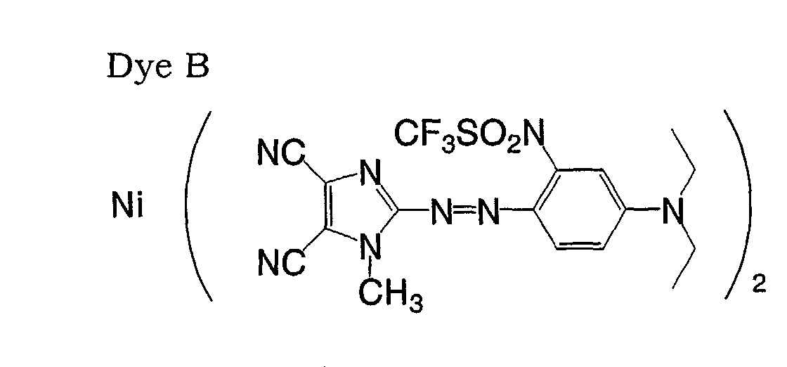
- An optical disk was prepared in the same manner as in Example 1, except that the following Dye B was used in place of Dye A.
- Dye B had no endothermic peak when subjected to the differential thermal analysis, which will be described below.
- Measurement environment under a flow of nitrogen gas (at a flow rate of 200 ml/minute)
- Table 1 indicates that while there is no significant difference between Example 1 and Comparative Example 1 at a linear recording velocity of 3.5 m/second, the LPP error rate in Example 1 is significantly lower than that in Comparative Example 1 at a linear recording velocity of 28 m/second.
- the method for optically recording information in which LPP error rate can be low even when information is recorded at a linear velocity of at least 14 m/s.
Landscapes
- Optical Record Carriers And Manufacture Thereof (AREA)
- Optical Recording Or Reproduction (AREA)
- Thermal Transfer Or Thermal Recording In General (AREA)
Abstract
Description

Measurement environment: under a flow of nitrogen gas (at a flow rate of 200 ml/minute)
Reference: an aluminum container with no optical disk
Measurement temperatures: 30 to 550°C
Rate of temperature rise: 10°C/minute

Claims (10)
- An optical information recording method comprising recording information at a linear velocity of at least 14 m/ s to an optical information recording medium comprising a substrate and a dye-containing recording layer formed on the substrate,
wherein the dye has an endothermic peak when subjected to differential thermal analysis under a flow of nitrogen gas. - The optical information recording method of claim 1, wherein the endothermic peak of the dye is 10 µVs/mg or more.
- The optical information recording method of claim 1 or 2, wherein the dye further has an exothermic peak.
- The optical information recording method of claim 3, wherein, in the dye, a total amount of endothermic heat is larger than a total amount of exothermic heat.
- The optical information recording method of any one of claims 1 to 4, wherein the optical information recording medium has a track pitch of 0.8 µm or less and a minimum pit length of pits formed by recording is 0.5 µm or less.
- An optical information recording medium comprising a substrate and a dye-containing recording layer formed on the substrate,
wherein the dye has an endothermic peak when subjected to differential thermal analysis under a flow of nitrogen gas, and the optical information recording medium is for being recorded with information at a linear velocity of at least 14 m/s. - The optical information recording medium of claim 6, wherein the endothermic peak of the dye is 10 µVs/mg or more.
- The optical information recording medium of claim 6 or 7, wherein the dye further has an exothermic peak.
- The optical information recording medium of claim 8, wherein a total amount of endothermic heat is larger than a total amount of exothermic heat.
- The optical information recording medium of any one of claims 6 to 9, having a track pitch of 0.8 µm or less,
wherein a minimum pit length of pits formed by recording is 0.5 µm or less.
Applications Claiming Priority (2)
| Application Number | Priority Date | Filing Date | Title |
|---|---|---|---|
| JP2003157781 | 2003-06-03 | ||
| JP2003157781A JP2004362644A (en) | 2003-06-03 | 2003-06-03 | Optical information recording method |
Publications (2)
| Publication Number | Publication Date |
|---|---|
| EP1484758A2 true EP1484758A2 (en) | 2004-12-08 |
| EP1484758A3 EP1484758A3 (en) | 2006-05-17 |
Family
ID=33157150
Family Applications (1)
| Application Number | Title | Priority Date | Filing Date |
|---|---|---|---|
| EP04253175A Withdrawn EP1484758A3 (en) | 2003-06-03 | 2004-05-28 | Optical information recording method |
Country Status (5)
| Country | Link |
|---|---|
| US (1) | US7378140B2 (en) |
| EP (1) | EP1484758A3 (en) |
| JP (1) | JP2004362644A (en) |
| CN (1) | CN100444262C (en) |
| TW (1) | TWI340383B (en) |
Family Cites Families (12)
| Publication number | Priority date | Publication date | Assignee | Title |
|---|---|---|---|---|
| US5952073A (en) * | 1996-11-08 | 1999-09-14 | Media Chemical Corp. | Dye composition for optical recording media having selected anions |
| EP0849727B1 (en) * | 1996-12-18 | 2006-03-15 | Mitsubishi Chemical Corporation | Optical recording disk |
| JPH10291366A (en) * | 1997-04-18 | 1998-11-04 | Toyo Ink Mfg Co Ltd | Optical recording medium and composition for optical recording medium |
| EP0996123B1 (en) * | 1998-10-21 | 2004-12-15 | Mitsubishi Chemical Corporation | Optical recording medium and optical recording method |
| JP3548929B2 (en) * | 1999-03-23 | 2004-08-04 | 太陽誘電株式会社 | Optical information recording medium |
| JP3673963B2 (en) * | 1999-12-01 | 2005-07-20 | 太陽誘電株式会社 | Optical information recording medium |
| JP2002059652A (en) * | 2000-08-18 | 2002-02-26 | Fuji Photo Film Co Ltd | Optical information recording medium |
| EP1313096A1 (en) * | 2000-08-25 | 2003-05-21 | Mitsubishi Chemical Corporation | Optical recording medium |
| JP2002140836A (en) | 2000-08-25 | 2002-05-17 | Mitsubishi Chemicals Corp | Optical recording medium |
| JP4143271B2 (en) | 2001-03-21 | 2008-09-03 | 株式会社リコー | Optical recording and playback method |
| US7144677B2 (en) * | 2001-03-21 | 2006-12-05 | Ricoh Company, Ltd. | Optical recording method and optical recording medium |
| JP2003020416A (en) * | 2001-07-06 | 2003-01-24 | Fuji Photo Film Co Ltd | Cyanine dye compound having specific structure with tetracyanoquinodimethane compound as counter anion, and optical information-recording medium including the cyanine dye |
-
2003
- 2003-06-03 JP JP2003157781A patent/JP2004362644A/en active Pending
-
2004
- 2004-05-28 EP EP04253175A patent/EP1484758A3/en not_active Withdrawn
- 2004-06-01 US US10/857,503 patent/US7378140B2/en not_active Expired - Fee Related
- 2004-06-02 TW TW093115725A patent/TWI340383B/en not_active IP Right Cessation
- 2004-06-02 CN CNB200410049213XA patent/CN100444262C/en not_active Expired - Fee Related
Also Published As
| Publication number | Publication date |
|---|---|
| JP2004362644A (en) | 2004-12-24 |
| TW200501150A (en) | 2005-01-01 |
| US7378140B2 (en) | 2008-05-27 |
| TWI340383B (en) | 2011-04-11 |
| CN100444262C (en) | 2008-12-17 |
| CN1573994A (en) | 2005-02-02 |
| EP1484758A3 (en) | 2006-05-17 |
| US20040247818A1 (en) | 2004-12-09 |
Similar Documents
| Publication | Publication Date | Title |
|---|---|---|
| US20030103442A1 (en) | Optical information recording medium | |
| JP4076739B2 (en) | Optical recording medium | |
| JP2005219326A (en) | Optical recording medium and image recording method | |
| JP2002269821A (en) | Optical information recording medium | |
| JP3617802B2 (en) | Optical information recording medium and information recording method | |
| JP4284025B2 (en) | Optical information recording medium | |
| US20050063292A1 (en) | Optical recording medium | |
| JP2003039830A (en) | Optical information recording medium | |
| JP4185270B2 (en) | Optical information recording medium and information recording method | |
| US20030210643A1 (en) | Optical information recording medium | |
| JP2004050612A (en) | Optical information recording medium and information recording method | |
| US7378140B2 (en) | Optical information recording method | |
| US7103897B2 (en) | Optical information recording medium | |
| JP2006040348A (en) | Optical recording medium and recording method | |
| EP1316951B1 (en) | Optical information recording medium | |
| US20030103443A1 (en) | Optical information recording medium | |
| JP4284036B2 (en) | Optical information recording medium | |
| JP4077612B2 (en) | Manufacturing method of optical information recording medium | |
| JP3742021B2 (en) | Optical information recording medium | |
| JP4098487B2 (en) | Optical information recording medium | |
| JP4119688B2 (en) | Optical information recording medium | |
| JP4160998B2 (en) | Optical information recording / reproducing method | |
| JP4284373B2 (en) | Optical information recording medium and optical information recording / reproducing method | |
| JP4156914B2 (en) | Optical recording medium and manufacturing method thereof | |
| JP2004199805A (en) | Optical information recording medium |
Legal Events
| Date | Code | Title | Description |
|---|---|---|---|
| PUAI | Public reference made under article 153(3) epc to a published international application that has entered the european phase |
Free format text: ORIGINAL CODE: 0009012 |
|
| AK | Designated contracting states |
Kind code of ref document: A2 Designated state(s): AT BE BG CH CY CZ DE DK EE ES FI FR GB GR HU IE IT LI LU MC NL PL PT RO SE SI SK TR |
|
| AX | Request for extension of the european patent |
Extension state: AL HR LT LV MK |
|
| PUAL | Search report despatched |
Free format text: ORIGINAL CODE: 0009013 |
|
| AK | Designated contracting states |
Kind code of ref document: A3 Designated state(s): AT BE BG CH CY CZ DE DK EE ES FI FR GB GR HU IE IT LI LU MC NL PL PT RO SE SI SK TR |
|
| AX | Request for extension of the european patent |
Extension state: AL HR LT LV MK |
|
| 17P | Request for examination filed |
Effective date: 20060913 |
|
| 17Q | First examination report despatched |
Effective date: 20061228 |
|
| AKX | Designation fees paid |
Designated state(s): DE FR GB |
|
| RAP1 | Party data changed (applicant data changed or rights of an application transferred) |
Owner name: FUJIFILM CORPORATION |
|
| STAA | Information on the status of an ep patent application or granted ep patent |
Free format text: STATUS: THE APPLICATION IS DEEMED TO BE WITHDRAWN |
|
| 18D | Application deemed to be withdrawn |
Effective date: 20081125 |