EP1484569A2 - Self-locking mounting bracket - Google Patents
Self-locking mounting bracket Download PDFInfo
- Publication number
- EP1484569A2 EP1484569A2 EP20040460021 EP04460021A EP1484569A2 EP 1484569 A2 EP1484569 A2 EP 1484569A2 EP 20040460021 EP20040460021 EP 20040460021 EP 04460021 A EP04460021 A EP 04460021A EP 1484569 A2 EP1484569 A2 EP 1484569A2
- Authority
- EP
- European Patent Office
- Prior art keywords
- manifold
- bracket
- mounting
- clasp
- cut
- Prior art date
- Legal status (The legal status is an assumption and is not a legal conclusion. Google has not performed a legal analysis and makes no representation as to the accuracy of the status listed.)
- Withdrawn
Links
- 238000005219 brazing Methods 0.000 claims abstract description 22
- 238000003825 pressing Methods 0.000 claims abstract description 4
- 239000011324 bead Substances 0.000 claims description 4
- 210000002105 tongue Anatomy 0.000 claims description 3
- 238000004519 manufacturing process Methods 0.000 abstract description 6
- 238000006073 displacement reaction Methods 0.000 abstract description 4
- 238000000034 method Methods 0.000 abstract description 4
- 238000001816 cooling Methods 0.000 abstract description 3
- 238000010276 construction Methods 0.000 abstract description 2
- 238000009877 rendering Methods 0.000 abstract 1
- 230000002349 favourable effect Effects 0.000 description 5
- 239000003795 chemical substances by application Substances 0.000 description 2
- 239000012634 fragment Substances 0.000 description 2
- 239000000155 melt Substances 0.000 description 2
- XAGFODPZIPBFFR-UHFFFAOYSA-N aluminium Chemical compound [Al] XAGFODPZIPBFFR-UHFFFAOYSA-N 0.000 description 1
- 229910052782 aluminium Inorganic materials 0.000 description 1
- 239000004411 aluminium Substances 0.000 description 1
- 239000011248 coating agent Substances 0.000 description 1
- 238000000576 coating method Methods 0.000 description 1
- 230000007423 decrease Effects 0.000 description 1
Images


Classifications
-
- F—MECHANICAL ENGINEERING; LIGHTING; HEATING; WEAPONS; BLASTING
- F28—HEAT EXCHANGE IN GENERAL
- F28F—DETAILS OF HEAT-EXCHANGE AND HEAT-TRANSFER APPARATUS, OF GENERAL APPLICATION
- F28F9/00—Casings; Header boxes; Auxiliary supports for elements; Auxiliary members within casings
- F28F9/001—Casings in the form of plate-like arrangements; Frames enclosing a heat exchange core
- F28F9/002—Casings in the form of plate-like arrangements; Frames enclosing a heat exchange core with fastening means for other structures
Definitions
- the invention relates to a self-locking mounting bracket for fastening on a pipeline, in particular on a heat exchanger manifold.
- Brackets of this kind are used as support points for fastening the exchanger to the bearing structure or as a basis for fixing other elements to the heat exchanger body, therefore the suitable rigidity, reliability of the attachment and resistance to mechanical vibrations generated during operation of the heat exchanger are necessary.
- the required reliability of the attachment is commonly achieved by brazing brackets to the manifold.
- special holders are applied or the components are preliminarily stitched together by a number of short welds.
- Self-locking brackets are also used.
- the patent US 5,183,103 discloses a mounting bracket comprising a pair of embracing portions capable of resiliently engaging the exterior of the manifold to keep the bracket in place prior to brazing of the components of the heat exchanger together.
- the bracket may be preliminarily connected to the heat exchanger manifold, without the need of using any special tools before the "one-shot" brazing operation, thus facilitating the manufacture of the heat exchanger. Since no additional appliances are necessary, it is possible to accommodate a larger number of heat exchangers in a furnace, hence substantially increasing production yield.
- bracket does not secure its vertical position. Bracket may be accidentally displaced e.g. during transport of a heat exchanger to a furnace before brazing. Accidental swivelling around the manifold tube is also possible.
- the aim of the present invention is to provide a single-unit bracket that enables easy, durable and detachable fastening to an arterial pipeline of any cross-section, preferably at a number of points along the bracket height.
- the aim of the present invention is, in particular, a bracket structure for a heat exchanger, enabling detachable preliminary fastening of the bracket to the heat exchanger manifold, preferably at a number of points along its height, before one-shot brazing process.
- a self-locking mounting bracket for fastening on a pipeline, in particular on a heat exchanger manifold, characterised in that it comprises at least two mounting clasps linked by a connecting surface and having a shape at least partially reflecting the pipeline cross-section, and at least one assembling surface, wherein the first mounting clasp comprises at least one cut-out substantially parallel to the manifold axis and the second mounting clasp is capable of snapping on the manifold and comprises at least one cut-out substantially perpendicular to the manifold axis and wherein the manifold comprises mounting projections for the cut-outs in the first and in the second clasp.
- bracket To attach the bracket to the manifold, one should tilt the bracket back at a certain angle to the manifold and slide the cut-outs of the first mounting clasp onto one pair of the mounting projections, then swivel the other end of the bracket towards the manifold and drive the cut-outs of the second clasp onto the corresponding mounting projections, thus locking the clasp to the manifold. Thanks to that the bracket is reliably attached.
- the cut-outs perpendicular to the manifold axis secure the bracket against displacement along the manifold axis, whereas the parallel cut-outs secure the bracket from swivelling around the manifold axis.
- the bracket has a form of an integral shape made by a pressing method.
- the bracket can be attached to the manifold at a number of locations along the manifold length. Under some circumstances, however, it may be favourable to provide only one pair or several pairs of projections, in order to render it possible to attach the bracket only at predetermined locations along the manifold length.
- the mounting projections have a form of convex beads on the manifold surface.
- the angular spacing of the second mounting clasp is greater than 180°.
- the second clasp engages behind the manifold axis, thus creating a snapping latch, which preserves the bracket from sliding out from the manifold.
- the second mounting clasp ends with mounting tongues that embrace the manifold cross-section.
- Said tongues enable the attachment of the bracket to manifolds of various cross-sections.
- the only requirement is that arms of the clasp should provide sufficient clamping force on the side of the manifold which is opposite the bracket.
- the cut-out that is substantially perpendicular to the manifold axis may turn upwardly, thus creating a snap fastener.
- bracket enables the application of the second clasps having angular spacing of less than 180°. This makes it possible to attach the bracket e.g. on a two-part partitioned manifold.
- the connecting surface of the bracket comprises corrugations substantially perpendicular to the bracket axis.
- corrugations The main purpose of said corrugations is to increase the crosswise rigidity of the bracket mounting surfaces, which serve either as attachment points for additional components of a heat exchanger, or support points for the heat exchanger itself. Moreover, such corrugations reduce the longitudinal rigidity of the bracket and render it possible to squeeze the bracket axially and attach it to the manifold even if the spacing between the corresponding mounting projections is slightly different to the distance between the end of the vertical cut-out of the first clasp and the cut-out of the second clasp.
- the connecting surface contacts the surface of the manifold, and the connecting surface and/or the manifold are coated with a brazing agent.
- Fig. 1 to Fig. 7 relate to a typical heat exchanger 1, having a cooling core 2 fluidly connected with two manifolds 3.
- the bracket 4 illustrated in Fig. 1 to Fig. 4 has the form of a single-unit profiled element manufactured of an aluminium sheet by a pressing method.
- the connecting surface 5 is shaped, from which two mounting surfaces 6 and 7 fork in two different directions.
- Each of the mounting surfaces has openings serving as mounting places of the bracket 4 after its attachment to a bearing structure, which is not shown in the drawings.
- Both the connecting surface 5 and the mounting surfaces 6 and 7 comprise corrugations 8 which increase the crosswise rigidity of the bracket.
- the connecting surface 5 develops, from its bottom side, to the first mounting clasp 9, and from its top side ⁇ to the second mounting clasp 10.
- the shapes of mounting clasps 9 and 10 correspond to the round cross-section of the manifold 3, wherein the angular spacing of clasps is greater than 180°, so that they engage around the manifold 3, behind its central axis.
- the first mounting clasps 9 has two cut-outs 91 (drawing Fig. 3) parallel and symmetrical to the manifold 3 axis, wherein the second mounting clasp 10 has two cut-outs 101 (drawing Fig. 4), perpendicular and symmetrical to the manifold 3 axis.
- the manifold 3 has on its both sides a number of pairs of mounting projections 31, disposed within equal distances along the length of the manifold. Integral multiple of the distance h between two neighbouring mounting projections is approximately equal to the distance H between the ends of the vertical cut-outs 91 in the first mounting clasp 9 and the cut-outs 101 in the second mounting clasp 10 (n ⁇ h ⁇ H). That enables attaching the bracket to the manifold at a number of locations along the manifold 3 length.
- the mounting projections 31 are shaped here as convex beads on the manifold 3 wall, made by means of chiselling the manifold 3 at certain points along its surface. In the presented embodiment, the total height H includes five mounting beads 31 located within equal distances h from one another.
- Attaching the bracket 4 to the manifold 3 is relatively simple. Firstly, having the bracket 4 tilted back at some angle to the manifold axis one should slide the cut-outs 91 of the firsts mounting clasp 9 onto one pair of the mounting projections 31. Then, having the one end of the bracket attached, one should swivel the bracket towards the manifold 3 and drive the cut-outs of the second clasp 10 till the clasp latches on around the manifold 3.
- the cut-outs 101 secure the bracket against displacement along the manifold axis, whereas the cut-outs 91 secure the bracket against rotation and detachment.
- Fig. 5 and Fig. 6 present another embodiment of the bracket according to the present invention.
- the bracket components that correspond to the ones from Fig. 1 to Fig. 4 are marked by the same reference numerals.
- the bracket 4 as shown in Fig. 5 has only one mounting surface 6, which is used for mounting a fan shroud (not shown in the drawing).
- the manifold 3 is manufactured as a two-part unit, composed of two semicircular plates 32 and 33, whereas the mounting projections have a form of cylindrical rods 31'.
- the shape of the mounting clasps 9 and 10 substantially reflect round cross-section of the manifold 3, however its angular spacing is less than 180°, so the clasp ends reach the protruding joint 34 between the plates 32 and 33 of the manifold 3.
- the first mounting clasp 9 comprises a pair of cut-outs 91 parallel to the manifold 3 axis, whereas the second clasp 10 has two cut-outs 101' which turn upwardly at their ends, thus creating a snap fastener 102.
- Attaching the bracket 4 to the manifold 3 consists of sliding the cut-outs 91 of the first mounting clasp 9 onto one pair of fixing rods 31'; swivelling the bracket towards the manifold 3; sliding the cut-outs 101' onto the corresponding pair of fixing rods 31' and finally lowering the bracket in order to lock the second mounting clasp 10 onto the manifold 3.
- the connecting surface 5 contacts the manifold surface and is coated from its inner side by a brazing agent, which during furnace brazing of the heat exchanger melts, providing a reliable and permanent fastening of the bracket 4 to the manifold 3.
- a brazing agent which during furnace brazing of the heat exchanger melts, providing a reliable and permanent fastening of the bracket 4 to the manifold 3.
- Fig. 7 presents one more embodiment of the bracket according to the present invention.
- the bracket was designed to be attached to the pipeline 3" having a pentagonal cross-section.
- the appropriate snapping latch arises exclusively by virtue of matching the clasp 10 with the arterial pipeline 3" shape.
- the application of clasps with cut-outs secures the bracket against displacement and rotation.
- the bracket can easily be attached and detached before brazing.
- no additional supporting facilities are necessary for brazing, which significantly reduces the working time and decreases the number of additional components required for assembling the heat exchanger, hence enabling manufacturing of the heat exchanger by means of the one-shot brazing operation.
Landscapes
- Engineering & Computer Science (AREA)
- Physics & Mathematics (AREA)
- Thermal Sciences (AREA)
- Mechanical Engineering (AREA)
- General Engineering & Computer Science (AREA)
- Details Of Heat-Exchange And Heat-Transfer (AREA)
Abstract
The invention relates to a self-locking mounting bracket (4) for fastening on a
pipeline, in particular on a heat exchanger manifold (3) having a cooling core (2)
fluidly connected with two manifolds (3). The bracket (4) has preferably a form of an
integral shape made by a pressing method, comprising of at least two mounting
clasps (9, 10) linked by connecting surface (5) and having a shape at least partially
reflecting the manifold (3) cross-section, and at least one assembling surface (6, 7).
The first mounting clasp (9) has at least one cut-out (91) substantially parallel to the
manifold (3) axis and the second mounting clasp (10) is capable of snapping on the
manifold (3) and has at least one cut-out (101) substantially perpendicular to the
manifold (3) axis. The manifold (3) comprises mounting projections (31, 31') for the
cut-outs in the first and in the second clasp (9, 10). Such construction of the
bracket (4) secures the bracket against displacement and rotation. The bracket can
easily be attached and detached before brazing. Moreover, no additional supporting
facilities are needed for brazing the bracket (4), thus rendering it possible to
manufacture the heat exchanger by means of one-shot brazing operation. After
assembling all the heat exchanger components together and attaching the bracket,
the exchanger is placed into a furnace, where it undergoes the one-shot brazing
process.
Description
- The invention relates to a self-locking mounting bracket for fastening on a pipeline, in particular on a heat exchanger manifold. Brackets of this kind are used as support points for fastening the exchanger to the bearing structure or as a basis for fixing other elements to the heat exchanger body, therefore the suitable rigidity, reliability of the attachment and resistance to mechanical vibrations generated during operation of the heat exchanger are necessary. The required reliability of the attachment is commonly achieved by brazing brackets to the manifold. To provide suitable stability during brazing, special holders are applied or the components are preliminarily stitched together by a number of short welds. Self-locking brackets are also used.
- The patent US 5,183,103 discloses a mounting bracket comprising a pair of embracing portions capable of resiliently engaging the exterior of the manifold to keep the bracket in place prior to brazing of the components of the heat exchanger together. The bracket may be preliminarily connected to the heat exchanger manifold, without the need of using any special tools before the "one-shot" brazing operation, thus facilitating the manufacture of the heat exchanger. Since no additional appliances are necessary, it is possible to accommodate a larger number of heat exchangers in a furnace, hence substantially increasing production yield.
- However, the locking of such a bracket does not secure its vertical position. Bracket may be accidentally displaced e.g. during transport of a heat exchanger to a furnace before brazing. Accidental swivelling around the manifold tube is also possible.
- The aim of the present invention is to provide a single-unit bracket that enables easy, durable and detachable fastening to an arterial pipeline of any cross-section, preferably at a number of points along the bracket height. The aim of the present invention is, in particular, a bracket structure for a heat exchanger, enabling detachable preliminary fastening of the bracket to the heat exchanger manifold, preferably at a number of points along its height, before one-shot brazing process.
- According to the present invention there is provided a self-locking mounting bracket for fastening on a pipeline, in particular on a heat exchanger manifold, characterised in that it comprises at least two mounting clasps linked by a connecting surface and having a shape at least partially reflecting the pipeline cross-section, and at least one assembling surface, wherein the first mounting clasp comprises at least one cut-out substantially parallel to the manifold axis and the second mounting clasp is capable of snapping on the manifold and comprises at least one cut-out substantially perpendicular to the manifold axis and wherein the manifold comprises mounting projections for the cut-outs in the first and in the second clasp.
- To attach the bracket to the manifold, one should tilt the bracket back at a certain angle to the manifold and slide the cut-outs of the first mounting clasp onto one pair of the mounting projections, then swivel the other end of the bracket towards the manifold and drive the cut-outs of the second clasp onto the corresponding mounting projections, thus locking the clasp to the manifold. Thanks to that the bracket is reliably attached. The cut-outs perpendicular to the manifold axis secure the bracket against displacement along the manifold axis, whereas the parallel cut-outs secure the bracket from swivelling around the manifold axis.
- Advantageously according to the present invention the bracket has a form of an integral shape made by a pressing method.
- It is also favourable according to the present invention, when the integral multiple (n) of the distance (h) between neighbouring mounting projections of the manifold is substantially equal to the distance (H) between the end of the parallel cut-out in the first mounting clasp and the end of the cut-out in the second mounting clasp (n·h ≅ H).
- Thanks to that, the bracket can be attached to the manifold at a number of locations along the manifold length. Under some circumstances, however, it may be favourable to provide only one pair or several pairs of projections, in order to render it possible to attach the bracket only at predetermined locations along the manifold length.
- Preferably the mounting projections have a form of convex beads on the manifold surface.
- This feature significantly reduces the manufacturing costs of the heat exchanger, as no additional fixing elements are necessary.
- Furthermore, it is favourable according to the present invention if the angular spacing of the second mounting clasp is greater than 180°.
- Thanks to that, the second clasp engages behind the manifold axis, thus creating a snapping latch, which preserves the bracket from sliding out from the manifold.
- Furthermore it is favourable if the second mounting clasp ends with mounting tongues that embrace the manifold cross-section.
- Said tongues enable the attachment of the bracket to manifolds of various cross-sections. The only requirement is that arms of the clasp should provide sufficient clamping force on the side of the manifold which is opposite the bracket.
- In a preferred embodiment of the bracket according to the present invention, the cut-out that is substantially perpendicular to the manifold axis may turn upwardly, thus creating a snap fastener.
- Such construction of the bracket enables the application of the second clasps having angular spacing of less than 180°. This makes it possible to attach the bracket e.g. on a two-part partitioned manifold.
- Furthermore, it is favourable if the connecting surface of the bracket comprises corrugations substantially perpendicular to the bracket axis.
- The main purpose of said corrugations is to increase the crosswise rigidity of the bracket mounting surfaces, which serve either as attachment points for additional components of a heat exchanger, or support points for the heat exchanger itself. Moreover, such corrugations reduce the longitudinal rigidity of the bracket and render it possible to squeeze the bracket axially and attach it to the manifold even if the spacing between the corresponding mounting projections is slightly different to the distance between the end of the vertical cut-out of the first clasp and the cut-out of the second clasp.
- After the preliminary attachment of the bracket it is advantageous to fasten the bracket permanently to the manifold by means of brazing.
- In such a case, according to the present invention it is advantageous if the connecting surface contacts the surface of the manifold, and the connecting surface and/or the manifold are coated with a brazing agent.
- During the furnace brazing said coating melts, providing a reliable and permanent fastening of the bracket to the manifold.
- The bracket according to the present invention is presented below by way of examples of preferred embodiments with reference to figures of the drawing, in which:
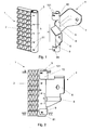
- Fig. 1 shows a fragment of a heat exchanger with manifold and the self-locking mounting bracket according to the present invention, in axonometric view, prior to an attachment,
- Fig. 2 shows a fragment of a heat exchanger with its manifold and the self-locking mounting bracket according to the present invention mounted on it, in lateral view,
- Fig. 3 shows the A-A section of Fig. 2,
- Fig. 4 shows the B-B section of Fig. 2,
- Fig. 5 shows another embodiment of the bracket according to the present invention, applicable to a two-part partitioned manifold, in axonometric view, prior to attachment,
- Fig. 6 shows the bracket from Fig. 5 after attachment to the manifold in a lateral view, and
- Fig. 7 shows yet another embodiment of the bracket according to the present invention, applicable to pipeline having pentagonal cross-sections.
-
- The embodiments shown in Fig. 1 to Fig. 7 relate to a
typical heat exchanger 1, having acooling core 2 fluidly connected with twomanifolds 3. - The
bracket 4 illustrated in Fig. 1 to Fig. 4 has the form of a single-unit profiled element manufactured of an aluminium sheet by a pressing method. Within the profiled element, the connectingsurface 5 is shaped, from which twomounting surfaces bracket 4 after its attachment to a bearing structure, which is not shown in the drawings. Both the connectingsurface 5 and themounting surfaces corrugations 8 which increase the crosswise rigidity of the bracket. - The connecting
surface 5 develops, from its bottom side, to thefirst mounting clasp 9, and from its top side ― to thesecond mounting clasp 10. The shapes of mountingclasps manifold 3, wherein the angular spacing of clasps is greater than 180°, so that they engage around themanifold 3, behind its central axis. - The
first mounting clasps 9 has two cut-outs 91 (drawing Fig. 3) parallel and symmetrical to themanifold 3 axis, wherein thesecond mounting clasp 10 has two cut-outs 101 (drawing Fig. 4), perpendicular and symmetrical to themanifold 3 axis. - The
manifold 3 has on its both sides a number of pairs ofmounting projections 31, disposed within equal distances along the length of the manifold. Integral multiple of the distance h between two neighbouring mounting projections is approximately equal to the distance H between the ends of the vertical cut-outs 91 in thefirst mounting clasp 9 and the cut-outs 101 in the second mounting clasp 10 (n·h ≅ H). That enables attaching the bracket to the manifold at a number of locations along themanifold 3 length. Themounting projections 31 are shaped here as convex beads on themanifold 3 wall, made by means of chiselling themanifold 3 at certain points along its surface. In the presented embodiment, the total height H includes fivemounting beads 31 located within equal distances h from one another. - Attaching the
bracket 4 to themanifold 3 is relatively simple. Firstly, having thebracket 4 tilted back at some angle to the manifold axis one should slide the cut-outs 91 of thefirsts mounting clasp 9 onto one pair of themounting projections 31. Then, having the one end of the bracket attached, one should swivel the bracket towards themanifold 3 and drive the cut-outs of thesecond clasp 10 till the clasp latches on around themanifold 3. The cut-outs 101 secure the bracket against displacement along the manifold axis, whereas the cut-outs 91 secure the bracket against rotation and detachment. - Fig. 5 and Fig. 6 present another embodiment of the bracket according to the present invention. The bracket components that correspond to the ones from Fig. 1 to Fig. 4 are marked by the same reference numerals.
- The
bracket 4, as shown in Fig. 5, has only onemounting surface 6, which is used for mounting a fan shroud (not shown in the drawing). - In this case, the
manifold 3 is manufactured as a two-part unit, composed of twosemicircular plates - The shape of the mounting
clasps manifold 3, however its angular spacing is less than 180°, so the clasp ends reach the protruding joint 34 between theplates manifold 3. - The
first mounting clasp 9 comprises a pair of cut-outs 91 parallel to the manifold 3 axis, whereas thesecond clasp 10 has two cut-outs 101' which turn upwardly at their ends, thus creating asnap fastener 102. - Attaching the
bracket 4 to themanifold 3 consists of sliding the cut-outs 91 of the first mountingclasp 9 onto one pair of fixing rods 31'; swivelling the bracket towards themanifold 3; sliding the cut-outs 101' onto the corresponding pair of fixing rods 31' and finally lowering the bracket in order to lock the second mountingclasp 10 onto themanifold 3. - For both embodiments described above, the connecting
surface 5 contacts the manifold surface and is coated from its inner side by a brazing agent, which during furnace brazing of the heat exchanger melts, providing a reliable and permanent fastening of thebracket 4 to themanifold 3. The above approach enables the manufacturing of a heat exchanger in a one-shot brazing process. After assembling of all the heat exchanger components, such as tubes, cooling fins, manifolds and side supports together and attaching necessary brackets to the exchanger, the exchanger is placed into a furnace, where it undergoes the one-shot brazing process. - Fig. 7 presents one more embodiment of the bracket according to the present invention. In this case the bracket was designed to be attached to the
pipeline 3" having a pentagonal cross-section. As shown, despite the fact that the angular spacing of the second clasp is less than 180°, and the bracket does not engage behind thepipeline 3" central axis, the appropriate snapping latch arises exclusively by virtue of matching theclasp 10 with thearterial pipeline 3" shape. - The application of clasps with cut-outs secures the bracket against displacement and rotation. The bracket can easily be attached and detached before brazing. Moreover, no additional supporting facilities are necessary for brazing, which significantly reduces the working time and decreases the number of additional components required for assembling the heat exchanger, hence enabling manufacturing of the heat exchanger by means of the one-shot brazing operation.
Claims (10)
- Self-locking mounting bracket for fastening on a pipeline, in particular on a heat exchanger manifold, characterised in that it comprises at least two mounting clasps (9, 10) linked by connecting surface (5) and having a shape at least partially reflecting the manifold (3) cross-section, and at least one assembling surface (6, 7), wherein the first mounting clasp (9) comprises at least one cut-out (91) substantially parallel to the manifold (3) axis and the second mounting clasp (10) is capable of snapping on the manifold (3) and comprises at least one cut-out (101) substantially perpendicular to the manifold (3) axis and wherein the manifold (3) comprises mounting projections (31, 31') for the cut-outs in the first and the second clasp (9, 10).
- A bracket as claimed in claim 1, characterised in that it has a form of an integral shape made by a pressing method.
- A bracket as claimed in claim 1 or 2, characterised in that the integral multiple of the distance (h) between neighbouring mounting projections (31, 31') of the manifold (3) is substantially equal to the distance (H) between the end of the parallel cut-out (91) in the first mounting clasp (9) and the end of the cut-out (101) in the second mounting clasp (10).
- A bracket as claimed in claim 1 or 2, characterised in that mounting projections (31) have a form of convex beads on the manifold (3) surface.
- A bracket as claimed in claim 1 or 2, characterised in that angular spacing of the second mounting clasp (10) is greater than 180°.
- A bracket as claimed in claim 1 or 2, characterised in that the second mounting clasp (10) ends with mounting tongues (103) embracing the manifold (3) cross-section.
- A bracket as claimed in claim 1 or 2, characterised in that the cut-out (101') substantially perpendicular to the manifold (3) axis, turns upwardly creating a snap fastener (102).
- A bracket as claimed in claim 1 or 2, characterised in that the connecting surface (5) comprises corrugations (8) substantially perpendicular to the bracket (4) axis.
- A bracket as claimed in claim 1 or 2, characterised in that it is permanently fastened to the manifold (3) by means of brazing.
- A bracket as claimed in claim 9, characterised in that the connecting surface (5) contacts the surface of the manifold (3) and the connecting surface (5) and/or the manifold (3) is coated with a brazing agent.
Applications Claiming Priority (2)
| Application Number | Priority Date | Filing Date | Title |
|---|---|---|---|
| PL36051103 | 2003-06-05 | ||
| PL03360511A PL360511A1 (en) | 2003-06-05 | 2003-06-05 | Self-acting snap fastening assembly bracket |
Publications (1)
| Publication Number | Publication Date |
|---|---|
| EP1484569A2 true EP1484569A2 (en) | 2004-12-08 |
Family
ID=33157456
Family Applications (1)
| Application Number | Title | Priority Date | Filing Date |
|---|---|---|---|
| EP20040460021 Withdrawn EP1484569A2 (en) | 2003-06-05 | 2004-06-03 | Self-locking mounting bracket |
Country Status (2)
| Country | Link |
|---|---|
| EP (1) | EP1484569A2 (en) |
| PL (1) | PL360511A1 (en) |
Cited By (4)
| Publication number | Priority date | Publication date | Assignee | Title |
|---|---|---|---|---|
| DE102004051207A1 (en) * | 2004-10-20 | 2006-05-04 | Behr Gmbh & Co. Kg | Arrangement for the mutual attachment of heat exchangers, in particular in a motor vehicle |
| DE102008047078A1 (en) | 2007-09-12 | 2009-05-20 | Behr Gmbh & Co. Kg | Heat exchanging unit for motor vehicle, has heat exchanger, particularly condenser, and manifolds that are arranged at sides of heat exchanger |
| US11338666B2 (en) | 2020-03-05 | 2022-05-24 | Denso International America, Inc. | Heat exchanging system |
| EP4148368A1 (en) * | 2021-09-08 | 2023-03-15 | Valeo Autosystemy SP. Z.O.O. | A heat exchanger |
Citations (1)
| Publication number | Priority date | Publication date | Assignee | Title |
|---|---|---|---|---|
| US5183103A (en) | 1990-10-31 | 1993-02-02 | Showa Aluminum Kabushiki Kaisha | Heat exchanger |
-
2003
- 2003-06-05 PL PL03360511A patent/PL360511A1/en not_active Application Discontinuation
-
2004
- 2004-06-03 EP EP20040460021 patent/EP1484569A2/en not_active Withdrawn
Patent Citations (1)
| Publication number | Priority date | Publication date | Assignee | Title |
|---|---|---|---|---|
| US5183103A (en) | 1990-10-31 | 1993-02-02 | Showa Aluminum Kabushiki Kaisha | Heat exchanger |
Cited By (5)
| Publication number | Priority date | Publication date | Assignee | Title |
|---|---|---|---|---|
| DE102004051207A1 (en) * | 2004-10-20 | 2006-05-04 | Behr Gmbh & Co. Kg | Arrangement for the mutual attachment of heat exchangers, in particular in a motor vehicle |
| DE102008047078A1 (en) | 2007-09-12 | 2009-05-20 | Behr Gmbh & Co. Kg | Heat exchanging unit for motor vehicle, has heat exchanger, particularly condenser, and manifolds that are arranged at sides of heat exchanger |
| US11338666B2 (en) | 2020-03-05 | 2022-05-24 | Denso International America, Inc. | Heat exchanging system |
| EP4148368A1 (en) * | 2021-09-08 | 2023-03-15 | Valeo Autosystemy SP. Z.O.O. | A heat exchanger |
| WO2023036885A1 (en) * | 2021-09-08 | 2023-03-16 | Valeo Autosystemy Sp. Z O.O. | A heat exchanger |
Also Published As
| Publication number | Publication date |
|---|---|
| PL360511A1 (en) | 2004-12-13 |
Similar Documents
| Publication | Publication Date | Title |
|---|---|---|
| AU644234B2 (en) | Heat exchanger | |
| US5429182A (en) | Heat exchanger having inlet and outlet pipes for a heat exchanging medium and a method of making same | |
| JP3912836B2 (en) | Heat exchanger | |
| KR0134668B1 (en) | Manifold assembly for a parallel flow heat exchanger | |
| CA2508510A1 (en) | Thermal cycling resistant tube to header joint for heat exchangers | |
| US6167953B1 (en) | Heat exchanger tank | |
| AU2004252192A1 (en) | Vibration-resistant mounting bracket for heat exchangers | |
| EP1219913A2 (en) | Improved side piece for heat exchangers | |
| EP0802386A1 (en) | Multi-tube heat exchanger | |
| JP4169407B2 (en) | Heat exchanger with mounting bracket | |
| MXPA02004903A (en) | Self-fixturing side piece for brazed heat exchangers. | |
| EP1517108A2 (en) | A heat exchanger | |
| JP2573419Y2 (en) | Support structure for inlet and outlet pipes of heat exchanger | |
| CA2590170A1 (en) | Bracket for mounting heat exchanger | |
| JP3517228B2 (en) | Heat exchanger manufacturing method | |
| CN114234676B (en) | Heat exchanger mounting structure | |
| JP2565703Y2 (en) | Heat exchanger mounting bracket assembly structure | |
| JP2004251493A (en) | Aluminum heat exchanger | |
| JP2578557B2 (en) | Heat exchanger | |
| JP2542550Y2 (en) | Mounting structure of mounting bracket in heat exchanger | |
| KR0140776Y1 (en) | Heat exchanger | |
| EP0818266B1 (en) | Method for manufacturing a multi-tube heat exchanger | |
| JP2546312Y2 (en) | Heat exchanger | |
| JPH0783538A (en) | Heat exchanger | |
| JPH073175Y2 (en) | Heat exchanger mounting structure |
Legal Events
| Date | Code | Title | Description |
|---|---|---|---|
| PUAI | Public reference made under article 153(3) epc to a published international application that has entered the european phase |
Free format text: ORIGINAL CODE: 0009012 |
|
| AK | Designated contracting states |
Kind code of ref document: A2 Designated state(s): AT BE BG CH CY CZ DE DK EE ES FI FR GB GR HU IE IT LI LU MC NL PL PT RO SE SI SK TR |
|
| AX | Request for extension of the european patent |
Extension state: AL HR LT LV MK |
|
| STAA | Information on the status of an ep patent application or granted ep patent |
Free format text: STATUS: THE APPLICATION IS DEEMED TO BE WITHDRAWN |
|
| 18D | Application deemed to be withdrawn |
Effective date: 20120103 |