EP1484536A1 - Mischarmatur - Google Patents
Mischarmatur Download PDFInfo
- Publication number
- EP1484536A1 EP1484536A1 EP04002629A EP04002629A EP1484536A1 EP 1484536 A1 EP1484536 A1 EP 1484536A1 EP 04002629 A EP04002629 A EP 04002629A EP 04002629 A EP04002629 A EP 04002629A EP 1484536 A1 EP1484536 A1 EP 1484536A1
- Authority
- EP
- European Patent Office
- Prior art keywords
- mixer
- stops
- spindles
- bores
- mixing valve
- Prior art date
- Legal status (The legal status is an assumption and is not a legal conclusion. Google has not performed a legal analysis and makes no representation as to the accuracy of the status listed.)
- Granted
Links
Images





Classifications
-
- E—FIXED CONSTRUCTIONS
- E03—WATER SUPPLY; SEWERAGE
- E03C—DOMESTIC PLUMBING INSTALLATIONS FOR FRESH WATER OR WASTE WATER; SINKS
- E03C1/00—Domestic plumbing installations for fresh water or waste water; Sinks
- E03C1/02—Plumbing installations for fresh water
- E03C1/04—Water-basin installations specially adapted to wash-basins or baths
- E03C1/0412—Constructional or functional features of the faucet handle
-
- E—FIXED CONSTRUCTIONS
- E03—WATER SUPPLY; SEWERAGE
- E03C—DOMESTIC PLUMBING INSTALLATIONS FOR FRESH WATER OR WASTE WATER; SINKS
- E03C1/00—Domestic plumbing installations for fresh water or waste water; Sinks
- E03C1/02—Plumbing installations for fresh water
- E03C1/04—Water-basin installations specially adapted to wash-basins or baths
-
- F—MECHANICAL ENGINEERING; LIGHTING; HEATING; WEAPONS; BLASTING
- F16—ENGINEERING ELEMENTS AND UNITS; GENERAL MEASURES FOR PRODUCING AND MAINTAINING EFFECTIVE FUNCTIONING OF MACHINES OR INSTALLATIONS; THERMAL INSULATION IN GENERAL
- F16K—VALVES; TAPS; COCKS; ACTUATING-FLOATS; DEVICES FOR VENTING OR AERATING
- F16K11/00—Multiple-way valves, e.g. mixing valves; Pipe fittings incorporating such valves
- F16K11/02—Multiple-way valves, e.g. mixing valves; Pipe fittings incorporating such valves with all movable sealing faces moving as one unit
- F16K11/06—Multiple-way valves, e.g. mixing valves; Pipe fittings incorporating such valves with all movable sealing faces moving as one unit comprising only sliding valves, i.e. sliding closure elements
- F16K11/072—Multiple-way valves, e.g. mixing valves; Pipe fittings incorporating such valves with all movable sealing faces moving as one unit comprising only sliding valves, i.e. sliding closure elements with pivoted closure members
- F16K11/074—Multiple-way valves, e.g. mixing valves; Pipe fittings incorporating such valves with all movable sealing faces moving as one unit comprising only sliding valves, i.e. sliding closure elements with pivoted closure members with flat sealing faces
Definitions
- Single-lever mixers allow simultaneous dosing of the cold and hot water supply, the mixing ratio usually by turning the lever is changed, the metering of the amount of water is carried out by a lever inclination.
- the lever can be rotated and inclined at the same time. This simultaneous control of the amount of water and the mixing ratio
- a three-dimensional lever movement often results in jerky opening the water supply with extreme water temperature (very hot / very cold) can be observed is.
- the invention seeks to remedy this.
- the invention is based on the object to create a mixer tap that enables convenient one-hand operation and clearly shows the mixing ratio of the media. According to the invention this task solved by the features of claim 1.
- a mixer tap is created which is convenient to operate with one hand enables and also the mixing ratio of the media clearly displays.
- the stops are on the outer area of the mixer housing arranged. This ensures that the handles are exactly one above the other and have an angle of rotation of 60 ° or 40 °.
- the stops are formed by dowel pins or notch pins. These are preferably used in bores in a body. This is on simple and therefore inexpensive way to limit rotation.
- the spindles are provided with toothings, which engage in the toothing of the drive rings.
- the spindles with bores for receiving provided by ball pins that fit into the ball seats of the drive rings ensures reliable transmission of motion from the handles to the spindles caused.
- an inexpensive manufacture is possible Can be actuated with little effort.
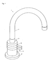
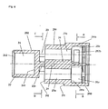
- the mixer tap 1 selected as an exemplary embodiment consists of a mixer housing 2, in which two spindles 3a, b are inserted. To operate are on the Mixing valve provided two rotary levers 4a, b, the movement of which is positive the spindles is transferable. At one end is partially in the mixer housing 2 a solder nipple 5 is used, which is held over a head nut 6 and on which an outlet pipe 7 is arranged. At its end facing away from the outlet pipe 7 the mixer tap is connected to a flange 8.
- the mixer housing 2 is rotationally symmetrical. It consists of one Body 20, which is composed of three cylinders 200, 201, 202 arranged one above the other is.
- the cylinders 200, 201, 202 have different diameters, whereby the cylinder 200 facing the flange 8 has the largest diameter, the middle cylinder 201 is smaller in relation to the cylinder 200 Diameter and the cylinder 202 facing away from the flange the smallest diameter Has. Due to the different diameters between the cylinders Paragraphs 21 are formed, which are referred to as stop surfaces 211 and 212.
- the mixing valve 2 At its end facing away from the flange 8 there is the mixing valve 2 with an external thread 22 provided, which corresponds to the head nut 6 in the assembled state. From the side facing away from the flange 8 there is one in the mixing valve 2 Bore 24 introduced, which has a bottom 241. On her the floor 241 A groove 242 is formed in the bore facing away from the end.
- cutouts 23 are provided at the end facing the cylinder 201 there are two in the cylinder 202 opposite cutouts 23 are provided.
- the cutouts 23 each have the shape of a segment of a circle, which is why the web 231 has a concave shape in plan view (FIG. 4, 5, 10, 13 and 14).
- On the longitudinal center line of the web 231 are adjacent on the outside 231 bores 29 made in the cylinder 201 to the web, which accommodate the stops 97 (Fig. 11).
- the stops 97 can, for example, in the form of notches or Dowel pins should be formed.
- the web 231 and the cylinders 200 and 201 are penetrated by two holes 26a, b.
- the bores 26a, b extend from that facing the flange 8 End of the cylinder 200 to the bottom 241 of the bore 24 into which the bores 26a, b open.
- the bores 26a, b are aligned parallel to one another and opposite one another arranged on one of the transverse center lines of the mixing housing 2.
- the cylinders 200 and 201 are also penetrated by two bores 27a, b.
- the Bores 27a, b are arranged offset by 90 ° to the bores 26a, b (Fig. 4, 5, 9, 10, 13 and 14).
- the bores 27a, b extend from that of the flange 8 facing end of the mixer tap 2 into the area of the cutouts 13 in Height of the abutment surfaces 212 of the cylinder 201.
- On their facing the flange Grooves 271 and 272 are formed in the bores 27a, b, respectively.
- the Groove 271 serves to receive an inlet disk 92; the groove 272 of the receptacle a lip seal 93.
- the bores 27a, b are in the region of the cylinder 200 executed remotely, causing holes 28a, b with a larger diameter are. At the transition of the bores 27a, b and 28a, b there are stop surfaces 281a, b. In the bores 28a, b there are connection chambers 282a, b arranged, which are crescent-shaped in plan view ( Figures 7 to 10). In the chambers 282a, b end the bores 26a, b, so that a connection between the Bores 26a, b and 28a, b is caused.
- the spindles 3a, b are arranged in the bores 27a, b. They instruct each their end facing away from the flange 8 on a spindle head 31a, b.
- the spindle heads 31a, b are in the embodiment of Figures 2, 4 and 5 with a toothing 311a, b; in the exemplary embodiment according to FIGS. 12, 13 and 14 are the spindle heads 31a, b without teeth and with a radial bore 312a, b for receiving a ball pin 313a, b provided in the bore 312a, b is arranged movably.
- the spindle heads 31a, b protrude into the area of the cutouts 23.
- the spindles 3a, b are with a Provide free cut 32a, b.
- a cylinder is connected to the cut 32a, b 33a, b, which is interrupted by two annular grooves 34a, b for receiving of O-rings 95, with the help of which the spindles 3a, b against the mixer housing 2 are sealed.
- a control cylinder with larger diameters with drivers 35a, b is formed.
- a stop surface 36a, b is produced by the diameter widening, that on the stop surface 28a, b of the mixer housing 2 with interposition a sliding washer 94 abuts.
- the drivers 35a, b serve to actuate the Control disc 91.
- the rotary levers 4a, b are designed essentially in the manner of a hollow cylinder 41a, b.
- the hollow cylinder is more annular Recognize part, on each of which a handle 43a, b is molded.
- the handles 43a, b are designed as pins; they are beyond can also be realized in the form of wings (FIGS. 2 and 12).
- the hollow cylinders 41a, b include paragraphs 201 and 202 of the mixer housing 2.
- In the area of the milling 23 of the mixer housing 2 is a drive ring on the inside of the hollow cylinder 41a 42a formed, the arc length of a third of the inner circumference of the hollow cylinder 41a.
- the drive ring 42a forms with the hollow cylinder 41a a groove 411.
- the hollow cylinder 41b of the rotary lever 4b has an inside diameter which is equal to the inner diameter of the hollow cylinder 41a.
- the hollow cylinder 41b is arranged immediately adjacent to the hollow cylinder 41a.
- a collar 412 is formed, which engages in the groove 411 of the rotary lever 4a.
- a drive ring 42b is arranged on the collar 412.
- the collar 412 including the drive ring 42b forms with the hollow cylinder 41b a groove 413 into which the hollow cylinder 41a is inserted with its end facing away from the flange 8.
- the arc length of the Drive ring 42b corresponds to that of drive ring 42a.
- Both drive rings 42a, b each have a stop trough 421 at their ends on.
- the stop troughs 421 correspond to the stops 97
- Interaction of the stop troughs 421 with the stops 97 is the angle of rotation the rotary lever 4a, b limited to 60 ° or 40 °.
- Due to the chosen geometry leads the abutment troughs 421 of the drive rings 42a, b to the respective opposite stop 97 to an exactly aligned one above the other Position of the handles 43 (Fig. 1, 2, 12). This results from the arrangement as an outside stop - In the exemplary embodiment by the arrangement of the stops 97 between Cylinder 202 of the mixer housing 2 and the hollow cylinders 41a, b on the extreme Area of the stop surface 212.
- the drive rings 42a, b provided with a toothing 422a, b which, when assembled, into the toothing 311a, b of the spindles 3a, b engage.
- the teeth 422a, b are as Degree gears formed.
- a ball seat 423a, b is provided in the drive rings 42a, b, in which grasp the ball pins 313a, b.
- the ball pins 313a, b are in the ball seats 323a, b kept mobile.
- the solder nipple 5 is inserted into the bore 24 of the mixer housing 2. It is rotationally symmetrical formed and has a collar 51 approximately in the center, which in the assembled Condition in the groove 242 of the bore 24 rests. At its flange 8 The end facing away from the solder nipple 5 is provided with a chamfer 52. Adjacent an annular groove 53 is arranged to the chamfer 52. On the flange 8 facing The side is formed cylindrical following the collar 51 of the solder nipple 5, wherein two ring grooves 54 are provided for receiving O-rings 96. With The solder nipple 5 is sealed against the mixer housing 2 with the aid of the O-rings 96.
- the solder nipple 5 is penetrated by a bore 55 which is different in two areas Diameter is divided.
- the area of larger diameter serves thereby as a mixing chamber 551, to which there is an outlet 552, which is a smaller one Diameter than the mixing chamber 551, connects.
- the free end of the Solder nipple 5 serves to receive the outlet pipe 7, the chamfer 52 being put over the pipe 7 facilitated.
- the end of the outlet pipe facing the flange 8 7 is supported in the assembled state on the collar 51.
- the head nut 6 is rotationally symmetrical. It has a guided tour on the outside 61, in which the hollow cylinder 41b of the rotary lever 4b is guided. It is inside provided with a thread 62 which is connected to the external thread 22 of the mixer housing 2 corresponds. Unscrewing the nut 6 fixes the Solder nipple 5 with outlet pipe 7 and the rotary lever 4a, b on the mixer housing 2.
- the flange 8 has two bores 81a, b, which with integrated connections for Hot and cold water are provided.
- the bores 81a, b are aligned with the bores 27a, b of the mixer housing 2.
- the bore serves in the exemplary embodiment 81a as hot water supply; the bore 81b as a cold water inlet.
- the flange 8 In the area of The end facing the mixer housing 2 is the flange 8 with flat contact surfaces 82a, b.
- the contact surfaces 82a, b are in contact with the lip seals 93, which are designed in a manner known per se.
- the control disks 91 are arranged in a rotationally fixed manner in the spindles 3a, b. You point each have a passage opening 911.
- the control disks 91 are preferably made of Ceramic made.
- the inlet disks 92 are rotationally fixed in the mixer housing 2 arranged. They also have passage openings 921 and are preferred also made of ceramic. Stand on the side facing the flange 8 the inlet washers 92 sealed in contact with the lip seals 93.
- Control disk 91 and inlet disk are in the basic position "mixer tap closed" 92 of the spindles 3a, b to one another such that the passage opening 921 of the respective inlet disk 92 is closed by the associated control disk 91 is.
- the handles 43 of the rotary levers 4a, b are exactly one above the other, wherein the stop grooves 421 of the drive rings 42a, b on opposite strike the stop pins 97.
- the water of the second inlet can be turned by rotating the rotary lever 4b released via bore 28b with connection chamber 282b and bore 26b become.
- the two water flows are mixed in the area of the soil 241 of the bore 24 and the mixing chamber 551 of the bore 55 in the solder nipple 5. From there, the mixture passes through the outlet 552 of the bore 55 of the solder nipple 5 into the outlet pipe 7.
- the mixing ratio can be adjusted via the positions of the Handles 43 of the rotary levers 4a, b can be clearly perceived. Are the handles 43 arranged one above the other, there is an equally distributed mixing ratio of Warm and cold water.
Landscapes
- Engineering & Computer Science (AREA)
- Health & Medical Sciences (AREA)
- Life Sciences & Earth Sciences (AREA)
- Hydrology & Water Resources (AREA)
- Public Health (AREA)
- Water Supply & Treatment (AREA)
- General Engineering & Computer Science (AREA)
- Mechanical Engineering (AREA)
- Multiple-Way Valves (AREA)
- Mixers Of The Rotary Stirring Type (AREA)
- Preparation Of Clay, And Manufacture Of Mixtures Containing Clay Or Cement (AREA)
Abstract
Description
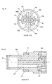
- Figur 1
- die dreidimensionale Darstellung einer Mischarmatur;
- Figur 2
- die in Figur 1 dargestellte Mischarmatur im Längsschnitt;
- Figur 3
- das Mischergehäuse der Mischarmatur in einer dreidimensionalen Darstellung;
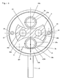
- Figur 4
- den Schnitt entlang der Linie II-II in Figur 2 (Ventile geschlossen);
- Figur 5
- den Schnitt entlang der Linie II-II in Figur 2 (Ventile offen);
- Figur 6
- das Mischergehäuse der Mischarmatur im Längsschnitt;
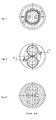
- Figur 7
- das Mischergehäuse gemäß Figur 6 in der Draufsicht;
- Figur 8
- das Mischergehäuse gemäß Figur 6 in der Untersicht;
- Figur 9
- den Schnitt entlang der Linie A-B in Figur 6;
- Figur 10
- den Schnitt entlang der Linie C-D in Figur 6;
- Figur 11
- den Schnitt entlang der Linie E-F in Figur 8;
- Figur 12
- die in Figur 1 dargestellte Mischarmatur in anderer Ausgestaltung im Längsschnitt;
- Figur 13
- den Schnitt entlang der Linie III-III in Figur 12 (Ventile geschlossen) und
- Figur 14
- den Schnitt entlang der Linie III-III in Figur 12 (Ventile offen).
Claims (10)
- Mischarmatur (1) mit einem Mischergehäuse (2), in dem zwei drehbare Spindeln (3a, b) angeordnet sind, die jeweils mit einer Steuerscheibe (91) im Eingriff stehen, welche jeweils mit einer drehfesten Einlassscheibe (92) in Berührung stehen, die mindestens eine Durchtrittsöffnung (921) aufweist, und die jeweils formschlüssig mit einem Drehhebel (4a, b) bedienbar sind und deren Drehwinkel durch Anschläge (97) begrenzt sind.
- Mischarmatur nach Anspruch 1, dadurch gekennzeichnet, dass die Anschläge (97) auf dem äusseren Bereich des Mischergehäuses (2) angeordnet sind.
- Mischarmatur nach Anspruch 1 oder 2, dadurch gekennzeichnet, dass die Anschläge (97) zwischen einem Zylinder (202) des Mischergehäuses (2) und Antriebskränzen (42a, b) der Drehhebel (4a, b) angeordnet sind.
- Mischarmatur nach Anspruch 2 oder 3, dadurch gekennzeichnet, dass die Anschläge (97) durch Pass- oder Kerbstifte gebildet sind.
- Mischarmatur nach Anspruch 4, dadurch gekennzeichnet, dass die Anschläge (97) in Bohrungen (29) eines Körpers (20) eingesetzt sind.
- Mischarmatur nach einem der Ansprüche 1 bis 5, dadurch gekennzeichnet, dass die Spindeln (3a, b) mit Verzahnungen (311a, b) versehen sind, die in Verzahnungen (422a, b) der Antriebskränze (42a, b) eingreifen.
- Mischarmatur nach einem der Ansprüche 1 bis 5, dadurch gekennzeichnet, dass die Spindeln (3a, b) mit Bohrungen (312a, b) zur Aufnahme von Kugelstiften (313a, b) versehen sind, die in Kugelsitze (423a, b) der Antriebskränze (42a, b) fassen.
- Mischarmatur nach einem der Ansprüche 1 bis 7, dadurch gekennzeichnet, dass die Drehhebel (4a, b) als Hohlzylinder (41a, b) ausgeführt sind, auf deren Innenseite jeweils die Zahnkränze (42a, b) angeordnet sind.
- Mischarmatur nach Anspruch 8, dadurch gekennzeichnet, dass die Bogenlänge der Zahnkränze (42a, b) etwa einem Drittel des Kreisumfangs der Innenwand des Hohlzylinders (41a, b) der Drehhebel (4a, b) entspricht.
- Mischarmatur nach einem der Ansprüche 1 bis 9, dadurch gekennzeichnet, dass ein Flansch (8) mit integrierten Anschlüssen für zwei Zuleitungen vorgesehen ist.
Applications Claiming Priority (2)
| Application Number | Priority Date | Filing Date | Title |
|---|---|---|---|
| DE20308906U DE20308906U1 (de) | 2003-06-06 | 2003-06-06 | Mischarmatur |
| DE20308906U | 2003-06-06 |
Publications (2)
| Publication Number | Publication Date |
|---|---|
| EP1484536A1 true EP1484536A1 (de) | 2004-12-08 |
| EP1484536B1 EP1484536B1 (de) | 2006-07-26 |
Family
ID=27816454
Family Applications (1)
| Application Number | Title | Priority Date | Filing Date |
|---|---|---|---|
| EP04002629A Expired - Lifetime EP1484536B1 (de) | 2003-06-06 | 2004-02-06 | Mischarmatur |
Country Status (4)
| Country | Link |
|---|---|
| EP (1) | EP1484536B1 (de) |
| AT (1) | ATE334330T1 (de) |
| DE (2) | DE20308906U1 (de) |
| ES (1) | ES2270188T3 (de) |
Cited By (3)
| Publication number | Priority date | Publication date | Assignee | Title |
|---|---|---|---|---|
| CN102003549A (zh) * | 2010-11-30 | 2011-04-06 | 厦门市易洁卫浴有限公司 | 一种直通旋转切换阀 |
| CN101639131B (zh) * | 2008-08-03 | 2011-06-01 | 邹建仁 | 旋钮式阀芯以及配置该旋钮式阀芯的水龙头 |
| CN107567520A (zh) * | 2015-03-04 | 2018-01-09 | 弗兰卡水系统股份公司 | 电子控制的卫浴配件 |
Families Citing this family (3)
| Publication number | Priority date | Publication date | Assignee | Title |
|---|---|---|---|---|
| DE10347819A1 (de) * | 2003-10-10 | 2005-05-04 | Grohe Water Tech Ag & Co Kg | Mischbatterie |
| US10184575B2 (en) * | 2017-01-11 | 2019-01-22 | Kohler Co. | Faucet with multi-directional controls |
| DE102018129625A1 (de) | 2018-11-23 | 2020-05-28 | Grohe Ag | Sanitärarmatur mit Mischventil und Ventil |
Citations (7)
| Publication number | Priority date | Publication date | Assignee | Title |
|---|---|---|---|---|
| DE583085C (de) * | 1932-01-26 | 1933-08-28 | Michel Theodorides | Misch- und Verteilerhahn |
| US2633872A (en) * | 1947-04-21 | 1953-04-07 | Vincent D Hennessey | Valve actuating mechanism and assemblage |
| FR2178384A5 (de) * | 1972-03-30 | 1973-11-09 | Adaglio Marie | |
| US4074697A (en) * | 1975-07-04 | 1978-02-21 | Lyng Industrier A-S Leksvikarmatur | Dual handle mixing faucet |
| FR2565658A1 (fr) * | 1984-06-07 | 1985-12-13 | Mbd Groupe Design | Dispositif melangeur pour robinetterie sanitaire |
| US4770392A (en) * | 1985-05-30 | 1988-09-13 | Fritz Schmidt | Shut-off device for pipes |
| DE19635614C1 (de) * | 1996-09-03 | 1998-04-23 | Ashauer Ernst | Wasserhahn |
-
2003
- 2003-06-06 DE DE20308906U patent/DE20308906U1/de not_active Expired - Lifetime
-
2004
- 2004-02-06 AT AT04002629T patent/ATE334330T1/de not_active IP Right Cessation
- 2004-02-06 DE DE502004001015T patent/DE502004001015D1/de not_active Expired - Fee Related
- 2004-02-06 EP EP04002629A patent/EP1484536B1/de not_active Expired - Lifetime
- 2004-02-06 ES ES04002629T patent/ES2270188T3/es not_active Expired - Lifetime
Patent Citations (7)
| Publication number | Priority date | Publication date | Assignee | Title |
|---|---|---|---|---|
| DE583085C (de) * | 1932-01-26 | 1933-08-28 | Michel Theodorides | Misch- und Verteilerhahn |
| US2633872A (en) * | 1947-04-21 | 1953-04-07 | Vincent D Hennessey | Valve actuating mechanism and assemblage |
| FR2178384A5 (de) * | 1972-03-30 | 1973-11-09 | Adaglio Marie | |
| US4074697A (en) * | 1975-07-04 | 1978-02-21 | Lyng Industrier A-S Leksvikarmatur | Dual handle mixing faucet |
| FR2565658A1 (fr) * | 1984-06-07 | 1985-12-13 | Mbd Groupe Design | Dispositif melangeur pour robinetterie sanitaire |
| US4770392A (en) * | 1985-05-30 | 1988-09-13 | Fritz Schmidt | Shut-off device for pipes |
| DE19635614C1 (de) * | 1996-09-03 | 1998-04-23 | Ashauer Ernst | Wasserhahn |
Cited By (4)
| Publication number | Priority date | Publication date | Assignee | Title |
|---|---|---|---|---|
| CN101639131B (zh) * | 2008-08-03 | 2011-06-01 | 邹建仁 | 旋钮式阀芯以及配置该旋钮式阀芯的水龙头 |
| CN102003549A (zh) * | 2010-11-30 | 2011-04-06 | 厦门市易洁卫浴有限公司 | 一种直通旋转切换阀 |
| CN102003549B (zh) * | 2010-11-30 | 2012-11-21 | 厦门市易洁卫浴有限公司 | 一种直通旋转切换阀 |
| CN107567520A (zh) * | 2015-03-04 | 2018-01-09 | 弗兰卡水系统股份公司 | 电子控制的卫浴配件 |
Also Published As
| Publication number | Publication date |
|---|---|
| EP1484536B1 (de) | 2006-07-26 |
| ATE334330T1 (de) | 2006-08-15 |
| ES2270188T3 (es) | 2007-04-01 |
| DE20308906U1 (de) | 2003-09-04 |
| DE502004001015D1 (de) | 2006-09-07 |
Similar Documents
| Publication | Publication Date | Title |
|---|---|---|
| DE3202040C2 (de) | ||
| DE2241638C3 (de) | Eingriff-Mischventil für Heiß- und Kaltwasser mit weitem Stellwinkel für die Mischungsregulierung | |
| DE2413420A1 (de) | Mischbatteriesystem | |
| DE102004018277B4 (de) | Mischventil für eine einarmige, nur durch Drehen betätigbare Mischbatterie | |
| DE69623637T2 (de) | Eine kugelventilkartusche für ein mischventil | |
| DE69128485T2 (de) | Mischventil mit einem kugelfoermigen ventilement | |
| DE2337614A1 (de) | Mischventil | |
| DE19756012A1 (de) | Wasserhahn-Handgriffbaugruppe | |
| EP1022634A1 (de) | Kartusche für Sanitärarmaturen | |
| DE2630037A1 (de) | Kalt- und warmwassermischhahn mit zwei bedienungshebeln | |
| EP1522777A1 (de) | Mischbatterie | |
| DE69227932T2 (de) | Mischventil mit einem kugelventil mit kragen | |
| DE2523342C3 (de) | Eingrirfwassermischhahn | |
| EP1484536B1 (de) | Mischarmatur | |
| EP0237473A1 (de) | Betätigungsanordnung in einer Einhebelmischarmatur | |
| DE3327776C2 (de) | ||
| DE1675471C3 (de) | Mischventil mit zwei voneinander unabhängigen Bedienungsgriffen | |
| EP4089304B1 (de) | Ventilkartusche | |
| EP1462692B1 (de) | Ventiloberteil für Armaturen | |
| DE4338701A1 (de) | Misch- und Absperrventil | |
| EP3702651B1 (de) | Ventiloberteil für sanitärarmaturen | |
| DE2627923A1 (de) | Mischarmatur fuer kalt- und warmwasser | |
| EP3112540A1 (de) | Ventiloberteil | |
| EP4137722B1 (de) | Ventilkartusche | |
| EP4428418B1 (de) | Ventiloberteil für sanitärarmaturen |
Legal Events
| Date | Code | Title | Description |
|---|---|---|---|
| PUAI | Public reference made under article 153(3) epc to a published international application that has entered the european phase |
Free format text: ORIGINAL CODE: 0009012 |
|
| AK | Designated contracting states |
Kind code of ref document: A1 Designated state(s): AT BE BG CH CY CZ DE DK EE ES FI FR GB GR HU IE IT LI LU MC NL PT RO SE SI SK TR |
|
| AX | Request for extension of the european patent |
Extension state: AL LT LV MK |
|
| 17P | Request for examination filed |
Effective date: 20050603 |
|
| AKX | Designation fees paid |
Designated state(s): AT BE BG CH CY CZ DE DK EE ES FI FR GB GR HU IE IT LI LU MC NL PT RO SE SI SK TR |
|
| GRAP | Despatch of communication of intention to grant a patent |
Free format text: ORIGINAL CODE: EPIDOSNIGR1 |
|
| GRAS | Grant fee paid |
Free format text: ORIGINAL CODE: EPIDOSNIGR3 |
|
| GRAA | (expected) grant |
Free format text: ORIGINAL CODE: 0009210 |
|
| AK | Designated contracting states |
Kind code of ref document: B1 Designated state(s): AT BE BG CH CY CZ DE DK EE ES FI FR GB GR HU IE IT LI LU MC NL PT RO SE SI SK TR |
|
| PG25 | Lapsed in a contracting state [announced via postgrant information from national office to epo] |
Ref country code: IT Free format text: LAPSE BECAUSE OF FAILURE TO SUBMIT A TRANSLATION OF THE DESCRIPTION OR TO PAY THE FEE WITHIN THE PRESCRIBED TIME-LIMIT;WARNING: LAPSES OF ITALIAN PATENTS WITH EFFECTIVE DATE BEFORE 2007 MAY HAVE OCCURRED AT ANY TIME BEFORE 2007. THE CORRECT EFFECTIVE DATE MAY BE DIFFERENT FROM THE ONE RECORDED. Effective date: 20060726 Ref country code: IE Free format text: LAPSE BECAUSE OF FAILURE TO SUBMIT A TRANSLATION OF THE DESCRIPTION OR TO PAY THE FEE WITHIN THE PRESCRIBED TIME-LIMIT Effective date: 20060726 Ref country code: FI Free format text: LAPSE BECAUSE OF FAILURE TO SUBMIT A TRANSLATION OF THE DESCRIPTION OR TO PAY THE FEE WITHIN THE PRESCRIBED TIME-LIMIT Effective date: 20060726 Ref country code: SK Free format text: LAPSE BECAUSE OF FAILURE TO SUBMIT A TRANSLATION OF THE DESCRIPTION OR TO PAY THE FEE WITHIN THE PRESCRIBED TIME-LIMIT Effective date: 20060726 Ref country code: RO Free format text: LAPSE BECAUSE OF FAILURE TO SUBMIT A TRANSLATION OF THE DESCRIPTION OR TO PAY THE FEE WITHIN THE PRESCRIBED TIME-LIMIT Effective date: 20060726 Ref country code: SI Free format text: LAPSE BECAUSE OF FAILURE TO SUBMIT A TRANSLATION OF THE DESCRIPTION OR TO PAY THE FEE WITHIN THE PRESCRIBED TIME-LIMIT Effective date: 20060726 Ref country code: NL Free format text: LAPSE BECAUSE OF FAILURE TO SUBMIT A TRANSLATION OF THE DESCRIPTION OR TO PAY THE FEE WITHIN THE PRESCRIBED TIME-LIMIT Effective date: 20060726 Ref country code: CZ Free format text: LAPSE BECAUSE OF FAILURE TO SUBMIT A TRANSLATION OF THE DESCRIPTION OR TO PAY THE FEE WITHIN THE PRESCRIBED TIME-LIMIT Effective date: 20060726 |
|
| REG | Reference to a national code |
Ref country code: GB Ref legal event code: FG4D Free format text: NOT ENGLISH |
|
| REG | Reference to a national code |
Ref country code: CH Ref legal event code: EP |
|
| REG | Reference to a national code |
Ref country code: IE Ref legal event code: FG4D Free format text: LANGUAGE OF EP DOCUMENT: GERMAN |
|
| REF | Corresponds to: |
Ref document number: 502004001015 Country of ref document: DE Date of ref document: 20060907 Kind code of ref document: P |
|
| PG25 | Lapsed in a contracting state [announced via postgrant information from national office to epo] |
Ref country code: SE Free format text: LAPSE BECAUSE OF FAILURE TO SUBMIT A TRANSLATION OF THE DESCRIPTION OR TO PAY THE FEE WITHIN THE PRESCRIBED TIME-LIMIT Effective date: 20061026 Ref country code: BG Free format text: LAPSE BECAUSE OF FAILURE TO SUBMIT A TRANSLATION OF THE DESCRIPTION OR TO PAY THE FEE WITHIN THE PRESCRIBED TIME-LIMIT Effective date: 20061026 Ref country code: DK Free format text: LAPSE BECAUSE OF FAILURE TO SUBMIT A TRANSLATION OF THE DESCRIPTION OR TO PAY THE FEE WITHIN THE PRESCRIBED TIME-LIMIT Effective date: 20061026 |
|
| GBT | Gb: translation of ep patent filed (gb section 77(6)(a)/1977) |
Effective date: 20061103 |
|
| PG25 | Lapsed in a contracting state [announced via postgrant information from national office to epo] |
Ref country code: PT Free format text: LAPSE BECAUSE OF FAILURE TO SUBMIT A TRANSLATION OF THE DESCRIPTION OR TO PAY THE FEE WITHIN THE PRESCRIBED TIME-LIMIT Effective date: 20061226 |
|
| NLV1 | Nl: lapsed or annulled due to failure to fulfill the requirements of art. 29p and 29m of the patents act | ||
| REG | Reference to a national code |
Ref country code: HU Ref legal event code: AG4A Ref document number: E000934 Country of ref document: HU |
|
| REG | Reference to a national code |
Ref country code: IE Ref legal event code: FD4D |
|
| PG25 | Lapsed in a contracting state [announced via postgrant information from national office to epo] |
Ref country code: MC Free format text: LAPSE BECAUSE OF NON-PAYMENT OF DUE FEES Effective date: 20070228 |
|
| ET | Fr: translation filed | ||
| REG | Reference to a national code |
Ref country code: ES Ref legal event code: FG2A Ref document number: 2270188 Country of ref document: ES Kind code of ref document: T3 |
|
| PLBE | No opposition filed within time limit |
Free format text: ORIGINAL CODE: 0009261 |
|
| STAA | Information on the status of an ep patent application or granted ep patent |
Free format text: STATUS: NO OPPOSITION FILED WITHIN TIME LIMIT |
|
| 26N | No opposition filed |
Effective date: 20070427 |
|
| BERE | Be: lapsed |
Owner name: FLUHS DREHTECHNIK G.M.B.H. Effective date: 20070228 |
|
| PG25 | Lapsed in a contracting state [announced via postgrant information from national office to epo] |
Ref country code: BE Free format text: LAPSE BECAUSE OF NON-PAYMENT OF DUE FEES Effective date: 20070228 |
|
| PG25 | Lapsed in a contracting state [announced via postgrant information from national office to epo] |
Ref country code: GR Free format text: LAPSE BECAUSE OF FAILURE TO SUBMIT A TRANSLATION OF THE DESCRIPTION OR TO PAY THE FEE WITHIN THE PRESCRIBED TIME-LIMIT Effective date: 20061027 |
|
| PGFP | Annual fee paid to national office [announced via postgrant information from national office to epo] |
Ref country code: DE Payment date: 20071224 Year of fee payment: 5 Ref country code: GB Payment date: 20080222 Year of fee payment: 5 Ref country code: IT Payment date: 20080226 Year of fee payment: 5 |
|
| PG25 | Lapsed in a contracting state [announced via postgrant information from national office to epo] |
Ref country code: AT Free format text: LAPSE BECAUSE OF NON-PAYMENT OF DUE FEES Effective date: 20070206 |
|
| PG25 | Lapsed in a contracting state [announced via postgrant information from national office to epo] |
Ref country code: EE Free format text: LAPSE BECAUSE OF FAILURE TO SUBMIT A TRANSLATION OF THE DESCRIPTION OR TO PAY THE FEE WITHIN THE PRESCRIBED TIME-LIMIT Effective date: 20060726 |
|
| REG | Reference to a national code |
Ref country code: CH Ref legal event code: PL |
|
| PG25 | Lapsed in a contracting state [announced via postgrant information from national office to epo] |
Ref country code: CH Free format text: LAPSE BECAUSE OF NON-PAYMENT OF DUE FEES Effective date: 20080229 Ref country code: LI Free format text: LAPSE BECAUSE OF NON-PAYMENT OF DUE FEES Effective date: 20080229 |
|
| PGFP | Annual fee paid to national office [announced via postgrant information from national office to epo] |
Ref country code: ES Payment date: 20080723 Year of fee payment: 5 |
|
| PGFP | Annual fee paid to national office [announced via postgrant information from national office to epo] |
Ref country code: FR Payment date: 20080718 Year of fee payment: 5 |
|
| PGFP | Annual fee paid to national office [announced via postgrant information from national office to epo] |
Ref country code: HU Payment date: 20080728 Year of fee payment: 5 |
|
| PG25 | Lapsed in a contracting state [announced via postgrant information from national office to epo] |
Ref country code: CY Free format text: LAPSE BECAUSE OF FAILURE TO SUBMIT A TRANSLATION OF THE DESCRIPTION OR TO PAY THE FEE WITHIN THE PRESCRIBED TIME-LIMIT Effective date: 20060726 Ref country code: LU Free format text: LAPSE BECAUSE OF NON-PAYMENT OF DUE FEES Effective date: 20070206 |
|
| PG25 | Lapsed in a contracting state [announced via postgrant information from national office to epo] |
Ref country code: TR Free format text: LAPSE BECAUSE OF FAILURE TO SUBMIT A TRANSLATION OF THE DESCRIPTION OR TO PAY THE FEE WITHIN THE PRESCRIBED TIME-LIMIT Effective date: 20060726 |
|
| GBPC | Gb: european patent ceased through non-payment of renewal fee |
Effective date: 20090206 |
|
| REG | Reference to a national code |
Ref country code: FR Ref legal event code: ST Effective date: 20091030 |
|
| PG25 | Lapsed in a contracting state [announced via postgrant information from national office to epo] |
Ref country code: HU Free format text: LAPSE BECAUSE OF NON-PAYMENT OF DUE FEES Effective date: 20090207 |
|
| PG25 | Lapsed in a contracting state [announced via postgrant information from national office to epo] |
Ref country code: DE Free format text: LAPSE BECAUSE OF NON-PAYMENT OF DUE FEES Effective date: 20090901 |
|
| REG | Reference to a national code |
Ref country code: ES Ref legal event code: FD2A Effective date: 20090207 |
|
| PG25 | Lapsed in a contracting state [announced via postgrant information from national office to epo] |
Ref country code: FR Free format text: LAPSE BECAUSE OF NON-PAYMENT OF DUE FEES Effective date: 20090302 Ref country code: GB Free format text: LAPSE BECAUSE OF NON-PAYMENT OF DUE FEES Effective date: 20090206 |
|
| PG25 | Lapsed in a contracting state [announced via postgrant information from national office to epo] |
Ref country code: ES Free format text: LAPSE BECAUSE OF NON-PAYMENT OF DUE FEES Effective date: 20090207 |