EP1484483A1 - Honeycomb filter - Google Patents
Honeycomb filter Download PDFInfo
- Publication number
- EP1484483A1 EP1484483A1 EP03707051A EP03707051A EP1484483A1 EP 1484483 A1 EP1484483 A1 EP 1484483A1 EP 03707051 A EP03707051 A EP 03707051A EP 03707051 A EP03707051 A EP 03707051A EP 1484483 A1 EP1484483 A1 EP 1484483A1
- Authority
- EP
- European Patent Office
- Prior art keywords
- honeycomb
- honeycomb filter
- central part
- axial direction
- segment
- Prior art date
- Legal status (The legal status is an assumption and is not a legal conclusion. Google has not performed a legal analysis and makes no representation as to the accuracy of the status listed.)
- Granted
Links
Images



Classifications
-
- F—MECHANICAL ENGINEERING; LIGHTING; HEATING; WEAPONS; BLASTING
- F01—MACHINES OR ENGINES IN GENERAL; ENGINE PLANTS IN GENERAL; STEAM ENGINES
- F01N—GAS-FLOW SILENCERS OR EXHAUST APPARATUS FOR MACHINES OR ENGINES IN GENERAL; GAS-FLOW SILENCERS OR EXHAUST APPARATUS FOR INTERNAL-COMBUSTION ENGINES
- F01N3/00—Exhaust or silencing apparatus having means for purifying, rendering innocuous, or otherwise treating exhaust
- F01N3/02—Exhaust or silencing apparatus having means for purifying, rendering innocuous, or otherwise treating exhaust for cooling, or for removing solid constituents of, exhaust
- F01N3/021—Exhaust or silencing apparatus having means for purifying, rendering innocuous, or otherwise treating exhaust for cooling, or for removing solid constituents of, exhaust by means of filters
- F01N3/022—Exhaust or silencing apparatus having means for purifying, rendering innocuous, or otherwise treating exhaust for cooling, or for removing solid constituents of, exhaust by means of filters characterised by specially adapted filtering structure, e.g. honeycomb, mesh or fibrous
-
- B—PERFORMING OPERATIONS; TRANSPORTING
- B01—PHYSICAL OR CHEMICAL PROCESSES OR APPARATUS IN GENERAL
- B01D—SEPARATION
- B01D45/00—Separating dispersed particles from gases or vapours by gravity, inertia, or centrifugal forces
- B01D45/12—Separating dispersed particles from gases or vapours by gravity, inertia, or centrifugal forces by centrifugal forces
- B01D45/16—Separating dispersed particles from gases or vapours by gravity, inertia, or centrifugal forces by centrifugal forces generated by the winding course of the gas stream, the centrifugal forces being generated solely or partly by mechanical means, e.g. fixed swirl vanes
-
- B—PERFORMING OPERATIONS; TRANSPORTING
- B01—PHYSICAL OR CHEMICAL PROCESSES OR APPARATUS IN GENERAL
- B01D—SEPARATION
- B01D46/00—Filters or filtering processes specially modified for separating dispersed particles from gases or vapours
- B01D46/24—Particle separators, e.g. dust precipitators, using rigid hollow filter bodies
- B01D46/2403—Particle separators, e.g. dust precipitators, using rigid hollow filter bodies characterised by the physical shape or structure of the filtering element
- B01D46/2418—Honeycomb filters
- B01D46/2425—Honeycomb filters characterized by parameters related to the physical properties of the honeycomb structure material
- B01D46/2429—Honeycomb filters characterized by parameters related to the physical properties of the honeycomb structure material of the honeycomb walls or cells
-
- B—PERFORMING OPERATIONS; TRANSPORTING
- B01—PHYSICAL OR CHEMICAL PROCESSES OR APPARATUS IN GENERAL
- B01D—SEPARATION
- B01D46/00—Filters or filtering processes specially modified for separating dispersed particles from gases or vapours
- B01D46/24—Particle separators, e.g. dust precipitators, using rigid hollow filter bodies
- B01D46/2403—Particle separators, e.g. dust precipitators, using rigid hollow filter bodies characterised by the physical shape or structure of the filtering element
- B01D46/2418—Honeycomb filters
- B01D46/2425—Honeycomb filters characterized by parameters related to the physical properties of the honeycomb structure material
- B01D46/24494—Thermal expansion coefficient, heat capacity or thermal conductivity
-
- B—PERFORMING OPERATIONS; TRANSPORTING
- B01—PHYSICAL OR CHEMICAL PROCESSES OR APPARATUS IN GENERAL
- B01D—SEPARATION
- B01D46/00—Filters or filtering processes specially modified for separating dispersed particles from gases or vapours
- B01D46/24—Particle separators, e.g. dust precipitators, using rigid hollow filter bodies
- B01D46/2403—Particle separators, e.g. dust precipitators, using rigid hollow filter bodies characterised by the physical shape or structure of the filtering element
- B01D46/2418—Honeycomb filters
- B01D46/2451—Honeycomb filters characterized by the geometrical structure, shape, pattern or configuration or parameters related to the geometry of the structure
- B01D46/2455—Honeycomb filters characterized by the geometrical structure, shape, pattern or configuration or parameters related to the geometry of the structure of the whole honeycomb or segments
-
- B—PERFORMING OPERATIONS; TRANSPORTING
- B01—PHYSICAL OR CHEMICAL PROCESSES OR APPARATUS IN GENERAL
- B01D—SEPARATION
- B01D46/00—Filters or filtering processes specially modified for separating dispersed particles from gases or vapours
- B01D46/24—Particle separators, e.g. dust precipitators, using rigid hollow filter bodies
- B01D46/2403—Particle separators, e.g. dust precipitators, using rigid hollow filter bodies characterised by the physical shape or structure of the filtering element
- B01D46/2418—Honeycomb filters
- B01D46/2451—Honeycomb filters characterized by the geometrical structure, shape, pattern or configuration or parameters related to the geometry of the structure
- B01D46/2459—Honeycomb filters characterized by the geometrical structure, shape, pattern or configuration or parameters related to the geometry of the structure of the plugs
-
- B—PERFORMING OPERATIONS; TRANSPORTING
- B01—PHYSICAL OR CHEMICAL PROCESSES OR APPARATUS IN GENERAL
- B01D—SEPARATION
- B01D46/00—Filters or filtering processes specially modified for separating dispersed particles from gases or vapours
- B01D46/24—Particle separators, e.g. dust precipitators, using rigid hollow filter bodies
- B01D46/2403—Particle separators, e.g. dust precipitators, using rigid hollow filter bodies characterised by the physical shape or structure of the filtering element
- B01D46/2418—Honeycomb filters
- B01D46/2451—Honeycomb filters characterized by the geometrical structure, shape, pattern or configuration or parameters related to the geometry of the structure
- B01D46/247—Honeycomb filters characterized by the geometrical structure, shape, pattern or configuration or parameters related to the geometry of the structure of the cells
-
- B—PERFORMING OPERATIONS; TRANSPORTING
- B01—PHYSICAL OR CHEMICAL PROCESSES OR APPARATUS IN GENERAL
- B01D—SEPARATION
- B01D46/00—Filters or filtering processes specially modified for separating dispersed particles from gases or vapours
- B01D46/24—Particle separators, e.g. dust precipitators, using rigid hollow filter bodies
- B01D46/2403—Particle separators, e.g. dust precipitators, using rigid hollow filter bodies characterised by the physical shape or structure of the filtering element
- B01D46/2418—Honeycomb filters
- B01D46/2451—Honeycomb filters characterized by the geometrical structure, shape, pattern or configuration or parameters related to the geometry of the structure
- B01D46/2474—Honeycomb filters characterized by the geometrical structure, shape, pattern or configuration or parameters related to the geometry of the structure of the walls along the length of the honeycomb
-
- B—PERFORMING OPERATIONS; TRANSPORTING
- B01—PHYSICAL OR CHEMICAL PROCESSES OR APPARATUS IN GENERAL
- B01D—SEPARATION
- B01D46/00—Filters or filtering processes specially modified for separating dispersed particles from gases or vapours
- B01D46/24—Particle separators, e.g. dust precipitators, using rigid hollow filter bodies
- B01D46/2403—Particle separators, e.g. dust precipitators, using rigid hollow filter bodies characterised by the physical shape or structure of the filtering element
- B01D46/2418—Honeycomb filters
- B01D46/2451—Honeycomb filters characterized by the geometrical structure, shape, pattern or configuration or parameters related to the geometry of the structure
- B01D46/2478—Structures comprising honeycomb segments
-
- B—PERFORMING OPERATIONS; TRANSPORTING
- B01—PHYSICAL OR CHEMICAL PROCESSES OR APPARATUS IN GENERAL
- B01D—SEPARATION
- B01D46/00—Filters or filtering processes specially modified for separating dispersed particles from gases or vapours
- B01D46/24—Particle separators, e.g. dust precipitators, using rigid hollow filter bodies
- B01D46/2403—Particle separators, e.g. dust precipitators, using rigid hollow filter bodies characterised by the physical shape or structure of the filtering element
- B01D46/2418—Honeycomb filters
- B01D46/2451—Honeycomb filters characterized by the geometrical structure, shape, pattern or configuration or parameters related to the geometry of the structure
- B01D46/2484—Cell density, area or aspect ratio
-
- B—PERFORMING OPERATIONS; TRANSPORTING
- B01—PHYSICAL OR CHEMICAL PROCESSES OR APPARATUS IN GENERAL
- B01D—SEPARATION
- B01D46/00—Filters or filtering processes specially modified for separating dispersed particles from gases or vapours
- B01D46/24—Particle separators, e.g. dust precipitators, using rigid hollow filter bodies
- B01D46/2403—Particle separators, e.g. dust precipitators, using rigid hollow filter bodies characterised by the physical shape or structure of the filtering element
- B01D46/2418—Honeycomb filters
- B01D46/2451—Honeycomb filters characterized by the geometrical structure, shape, pattern or configuration or parameters related to the geometry of the structure
- B01D46/2486—Honeycomb filters characterized by the geometrical structure, shape, pattern or configuration or parameters related to the geometry of the structure characterised by the shapes or configurations
-
- B—PERFORMING OPERATIONS; TRANSPORTING
- B01—PHYSICAL OR CHEMICAL PROCESSES OR APPARATUS IN GENERAL
- B01D—SEPARATION
- B01D46/00—Filters or filtering processes specially modified for separating dispersed particles from gases or vapours
- B01D46/24—Particle separators, e.g. dust precipitators, using rigid hollow filter bodies
- B01D46/2403—Particle separators, e.g. dust precipitators, using rigid hollow filter bodies characterised by the physical shape or structure of the filtering element
- B01D46/2418—Honeycomb filters
- B01D46/2451—Honeycomb filters characterized by the geometrical structure, shape, pattern or configuration or parameters related to the geometry of the structure
- B01D46/2486—Honeycomb filters characterized by the geometrical structure, shape, pattern or configuration or parameters related to the geometry of the structure characterised by the shapes or configurations
- B01D46/2488—Triangular
-
- B—PERFORMING OPERATIONS; TRANSPORTING
- B01—PHYSICAL OR CHEMICAL PROCESSES OR APPARATUS IN GENERAL
- B01D—SEPARATION
- B01D46/00—Filters or filtering processes specially modified for separating dispersed particles from gases or vapours
- B01D46/24—Particle separators, e.g. dust precipitators, using rigid hollow filter bodies
- B01D46/2403—Particle separators, e.g. dust precipitators, using rigid hollow filter bodies characterised by the physical shape or structure of the filtering element
- B01D46/2418—Honeycomb filters
- B01D46/2451—Honeycomb filters characterized by the geometrical structure, shape, pattern or configuration or parameters related to the geometry of the structure
- B01D46/2486—Honeycomb filters characterized by the geometrical structure, shape, pattern or configuration or parameters related to the geometry of the structure characterised by the shapes or configurations
- B01D46/249—Quadrangular e.g. square or diamond
-
- B—PERFORMING OPERATIONS; TRANSPORTING
- B01—PHYSICAL OR CHEMICAL PROCESSES OR APPARATUS IN GENERAL
- B01D—SEPARATION
- B01D46/00—Filters or filtering processes specially modified for separating dispersed particles from gases or vapours
- B01D46/24—Particle separators, e.g. dust precipitators, using rigid hollow filter bodies
- B01D46/2403—Particle separators, e.g. dust precipitators, using rigid hollow filter bodies characterised by the physical shape or structure of the filtering element
- B01D46/2418—Honeycomb filters
- B01D46/2451—Honeycomb filters characterized by the geometrical structure, shape, pattern or configuration or parameters related to the geometry of the structure
- B01D46/2486—Honeycomb filters characterized by the geometrical structure, shape, pattern or configuration or parameters related to the geometry of the structure characterised by the shapes or configurations
- B01D46/2492—Hexagonal
-
- B—PERFORMING OPERATIONS; TRANSPORTING
- B01—PHYSICAL OR CHEMICAL PROCESSES OR APPARATUS IN GENERAL
- B01D—SEPARATION
- B01D46/00—Filters or filtering processes specially modified for separating dispersed particles from gases or vapours
- B01D46/24—Particle separators, e.g. dust precipitators, using rigid hollow filter bodies
- B01D46/2403—Particle separators, e.g. dust precipitators, using rigid hollow filter bodies characterised by the physical shape or structure of the filtering element
- B01D46/2418—Honeycomb filters
- B01D46/2498—The honeycomb filter being defined by mathematical relationships
-
- F—MECHANICAL ENGINEERING; LIGHTING; HEATING; WEAPONS; BLASTING
- F01—MACHINES OR ENGINES IN GENERAL; ENGINE PLANTS IN GENERAL; STEAM ENGINES
- F01N—GAS-FLOW SILENCERS OR EXHAUST APPARATUS FOR MACHINES OR ENGINES IN GENERAL; GAS-FLOW SILENCERS OR EXHAUST APPARATUS FOR INTERNAL-COMBUSTION ENGINES
- F01N3/00—Exhaust or silencing apparatus having means for purifying, rendering innocuous, or otherwise treating exhaust
- F01N3/02—Exhaust or silencing apparatus having means for purifying, rendering innocuous, or otherwise treating exhaust for cooling, or for removing solid constituents of, exhaust
- F01N3/021—Exhaust or silencing apparatus having means for purifying, rendering innocuous, or otherwise treating exhaust for cooling, or for removing solid constituents of, exhaust by means of filters
- F01N3/022—Exhaust or silencing apparatus having means for purifying, rendering innocuous, or otherwise treating exhaust for cooling, or for removing solid constituents of, exhaust by means of filters characterised by specially adapted filtering structure, e.g. honeycomb, mesh or fibrous
- F01N3/0222—Exhaust or silencing apparatus having means for purifying, rendering innocuous, or otherwise treating exhaust for cooling, or for removing solid constituents of, exhaust by means of filters characterised by specially adapted filtering structure, e.g. honeycomb, mesh or fibrous the structure being monolithic, e.g. honeycombs
-
- B—PERFORMING OPERATIONS; TRANSPORTING
- B01—PHYSICAL OR CHEMICAL PROCESSES OR APPARATUS IN GENERAL
- B01D—SEPARATION
- B01D46/00—Filters or filtering processes specially modified for separating dispersed particles from gases or vapours
- B01D46/24—Particle separators, e.g. dust precipitators, using rigid hollow filter bodies
- B01D46/2403—Particle separators, e.g. dust precipitators, using rigid hollow filter bodies characterised by the physical shape or structure of the filtering element
- B01D46/2418—Honeycomb filters
- B01D46/2451—Honeycomb filters characterized by the geometrical structure, shape, pattern or configuration or parameters related to the geometry of the structure
- B01D46/2482—Thickness, height, width, length or diameter
-
- F—MECHANICAL ENGINEERING; LIGHTING; HEATING; WEAPONS; BLASTING
- F01—MACHINES OR ENGINES IN GENERAL; ENGINE PLANTS IN GENERAL; STEAM ENGINES
- F01N—GAS-FLOW SILENCERS OR EXHAUST APPARATUS FOR MACHINES OR ENGINES IN GENERAL; GAS-FLOW SILENCERS OR EXHAUST APPARATUS FOR INTERNAL-COMBUSTION ENGINES
- F01N2260/00—Exhaust treating devices having provisions not otherwise provided for
- F01N2260/10—Exhaust treating devices having provisions not otherwise provided for for avoiding stress caused by expansions or contractions due to temperature variations
-
- F—MECHANICAL ENGINEERING; LIGHTING; HEATING; WEAPONS; BLASTING
- F01—MACHINES OR ENGINES IN GENERAL; ENGINE PLANTS IN GENERAL; STEAM ENGINES
- F01N—GAS-FLOW SILENCERS OR EXHAUST APPARATUS FOR MACHINES OR ENGINES IN GENERAL; GAS-FLOW SILENCERS OR EXHAUST APPARATUS FOR INTERNAL-COMBUSTION ENGINES
- F01N2260/00—Exhaust treating devices having provisions not otherwise provided for
- F01N2260/18—Exhaust treating devices having provisions not otherwise provided for for improving rigidity, e.g. by wings, ribs
-
- F—MECHANICAL ENGINEERING; LIGHTING; HEATING; WEAPONS; BLASTING
- F01—MACHINES OR ENGINES IN GENERAL; ENGINE PLANTS IN GENERAL; STEAM ENGINES
- F01N—GAS-FLOW SILENCERS OR EXHAUST APPARATUS FOR MACHINES OR ENGINES IN GENERAL; GAS-FLOW SILENCERS OR EXHAUST APPARATUS FOR INTERNAL-COMBUSTION ENGINES
- F01N2330/00—Structure of catalyst support or particle filter
- F01N2330/30—Honeycomb supports characterised by their structural details
- F01N2330/48—Honeycomb supports characterised by their structural details characterised by the number of flow passages, e.g. cell density
-
- Y—GENERAL TAGGING OF NEW TECHNOLOGICAL DEVELOPMENTS; GENERAL TAGGING OF CROSS-SECTIONAL TECHNOLOGIES SPANNING OVER SEVERAL SECTIONS OF THE IPC; TECHNICAL SUBJECTS COVERED BY FORMER USPC CROSS-REFERENCE ART COLLECTIONS [XRACs] AND DIGESTS
- Y02—TECHNOLOGIES OR APPLICATIONS FOR MITIGATION OR ADAPTATION AGAINST CLIMATE CHANGE
- Y02T—CLIMATE CHANGE MITIGATION TECHNOLOGIES RELATED TO TRANSPORTATION
- Y02T10/00—Road transport of goods or passengers
- Y02T10/10—Internal combustion engine [ICE] based vehicles
- Y02T10/12—Improving ICE efficiencies
-
- Y—GENERAL TAGGING OF NEW TECHNOLOGICAL DEVELOPMENTS; GENERAL TAGGING OF CROSS-SECTIONAL TECHNOLOGIES SPANNING OVER SEVERAL SECTIONS OF THE IPC; TECHNICAL SUBJECTS COVERED BY FORMER USPC CROSS-REFERENCE ART COLLECTIONS [XRACs] AND DIGESTS
- Y10—TECHNICAL SUBJECTS COVERED BY FORMER USPC
- Y10S—TECHNICAL SUBJECTS COVERED BY FORMER USPC CROSS-REFERENCE ART COLLECTIONS [XRACs] AND DIGESTS
- Y10S55/00—Gas separation
- Y10S55/30—Exhaust treatment
Definitions
- the present invention relates to a honeycomb filter for trapping particulate matter contained in dust-containing fluid such as exhaust gas emitted from a diesel engine.
- a honeycomb structure has heretofore been used as a filter for trapping particulate matter contained in a dust-containing fluid such as exhaust gas emitted from a diesel engine.
- the rapid temperature change of exhaust gas and the local heating easily makes non-uniform the temperature distribution inside the honeycomb structure, which makes problems such as crack generation in the honeycomb structure and the like.
- the honeycomb structure is used particularly as a filter for trapping particulate matter in exhaust gas emitted from a diesel engine, it is necessary to burn the fine carbon particles deposited on the filter to remove the particles and regenerate the filter. In that case, high temperatures are inevitably generated locally in the filter. As a result, a large thermal stress and cracks tend to be generated.
- the thermal stress is generated because thermal expansion/deformation of each part of the honeycomb structure differs by the non-uniformity of the temperature distribution, in which the temperature of a central part becomes higher than that of a peripheral part, and the parts are mutually restrained and are not freely deformable.
- the above-described problem is remarkable especially in a honeycomb filter of SiC. That is, through the honeycomb filter of SiC is superior in heat resistance, the filter disadvantageously has a coefficient of thermal expansion which is higher than that of a conventionally-known cordierite honeycomb filter, and is inferior to the conventional filter in a thermal shock resistance.
- the present invention has been developed in consideration of the conventional problems and aims to provide a honeycomb filter in which a crack is not generated by thermal stress generated at a use time, especially at a regeneration time and which is superior in durability.
- a honeycomb filter for trapping particulate matter contained in dust-containing fluid, the filter comprising a number of through-holes surrounded by partition walls and extending in an axial direction, the partition walls having filterability, predetermined through-hales being plugged at one end, remaining through-holes being plugged at the other end, wherein in a section of the honeycomb filter perpendicular to the axial direction, a heat capacity in a central part of the honeycomb filter is higher than that in a peripheral part of the honeycomb filter.
- a honeycomb filter for trapping particulate matter contained in dust-containing fluid, the filter comprising a number of through-holes surrounded by partition walls and extending in an axial direction, the partition walls having filterability, predetermined through-hales being plugged at one end, remaining through-holes being plugged at the other end, wherein the honeycomb filter comprises an assembly of a plurality of honeycomb segments, and in a section of each honeycomb segment perpendicular to the axial direction, a heat capacity of a central part of the honeycomb filter is higher than that of a peripheral part of the honeycomb filter.
- a heat capacity of the central part of the honeycomb filter or the central part of each honeycomb segment is set to be higher than that of a peripheral part are as follows:
- a sectional area of the central part of the honeycomb segment is set to preferably 40 to 90% of that of the whole honeycomb segment in the section of the honeycomb filter perpendicular to the axial direction.
- a material for the honeycomb filter preferably contains one selected from the group consisting of SiC, Si 3 N 4 , alumina, mullite, aluminum titanate, zirconium phosphate, and lithium aluminum silicate as a main crystal phase, and especially SiC is preferable because its heat resistance is superior.
- the sectional shape of the through-holes of the honeycomb filter is preferably any of a triangle, a tetragon, a hexagon and a corrugated shape from the standpoint of production.
- the honeycomb segment preferably carries a catalyst because the filter not only traps the particulate matter but also has a function of purifying the exhaust gas or the like is provided, and the catalyst further preferably contains at least one of Pt, Pd, Rh, K, Li, and Na.
- a section of the filter perpendicular to the axial direction is formed in such a manner that a heat capacity of a central part of the honeycomb filter is higher than that of a peripheral part or that a heat capacity of a central part of a honeycomb segment is higher than that of a peripheral part of the honeycomb segment. Accordingly, during use, especially at a regeneration time, a temperature rise in the central part whose temperature tends to rise more easily than in the peripheral part is suppressed, and a temperature difference between the central part and the peripheral part can be reduced. Therefore, cracks can be inhibited from being generated even by thermal stress caused in the honeycomb filter, and the filter is remarkably superior in durability.
- the present invention is a honeycomb filter for trapping particulate matter contained in a dust-containing fluid.
- the filter has a number of through-holes surrounded by partition walls and extending in an axial direction, the partition walls of the through-holes have filterability, predetermined through-holes are plugged at one end portion, and the remaining through-holes are plugged at the other end portion.
- the honeycomb filter is constituted by a single body.
- the honeycomb filter comprises a plurality of honeycomb segments, and the respective honeycomb segments are bonded via a bonding material to constitute the honeycomb filter.
- the end portions of the through-holes which are not usually plugged are plugged in the central part of the end face of the honeycomb filter in the axial direction.
- the end portions of through-holes 12 are usually alternately plugged.
- the end portions of the through-holes 12 which are not usually plugged are further plugged. Accordingly, the heat capacity of the central part 11 can be set to be larger than that of a peripheral part 13.
- the object to set the heat capacity of the central part 11 to be larger than that of the peripheral part 13 can be achieved also when a plugging depth is increased in the central part 11 among the plugged end portions of the through-holes 12.
- an area range of the central part is set to 20 to 90% of that of a sectional area of the honeycomb filter (or the honeycomb segment).
- the region of the central part include a region surrounded by a shape analogous to a sectional shape of an outer peripheral surface centering on a center point on the section of the honeycomb filter (or the honeycomb segment), and a region surrounded by a circle centering on the center point.
- the area range of the central part is preferably 40 to 90%, further preferably 50 to 90% of the sectional area of the honeycomb filter (or the honeycomb segment).
- the thickness of the partition wall in the central part of the section of the honeycomb filter perpendicular to the axial direction is set to be larger than that of the partition wall in the peripheral part.
- the thickness of a partition wall 14a in the central part 11 is formed to be larger than that of a partition wall 14b in the peripheral part 13. Accordingly, the heat capacity of the central part 11 can be set to be higher than that of the peripheral part 13. Furthermore, in this constitution, resistance at a time when the exhaust gas passes through the partition wall in the central part of the honeycomb filter increases as compared with that in the peripheral part. Therefore, the amount of exhaust gas flowing through the central part of the honeycomb filter drops, and an amount of deposited particulate matter is also decreased.
- the amount of heat generated in the central part of the honeycomb filter at the regeneration time relatively drops as compared with the outer peripheral part, temperature distribution of the honeycomb filter in a sectional direction is uniformalized, and a problem that the honeycomb filter is cracked at the regeneration time is solved.
- the heat capacity of the central part 11 can be set to be larger than that of the peripheral part 13 in the same manner as described above.
- honeycomb filter comprises a plurality of honeycomb segments and the respective honeycomb segments are bonded by the bonding material to constitute the honeycomb filter.
- the heat capacity of the filter central part can be set to be larger than that of the peripheral part by various embodiments as described below.
- the heat capacity of the central part of each honeycomb segment can be set to be larger than that of the peripheral part.
- honeycomb segments 15 are bonded to one another by a bonding material 20 only in the central part of the honeycomb filter 10.
- the thickness of the partition wall of a honeycomb segment 15a positioned in the central part 11 is set to be larger than that of the partition wall of a honeycomb segment 15b positioned in the peripheral part 13 in section of the honeycomb filter 10 perpendicular to the axial direction.
- the amount of deposited particulate matter can be decreased. Therefore, the amount of heat generated in the central part of the honeycomb segment at the regeneration time relatively drops as compared with the outer peripheral part, and a problem that the honeycomb segment is cracked at the regeneration time is solved.
- a bonding material 20a for use in bonding the honeycomb segment 15a positioned in the central part 11 is formed to be thicker than a bonding material 20b for use in bonding the honeycomb segment 15b positioned in the peripheral part 13.
- the thermal conductivity of the honeycomb segment positioned in the central part is set to be larger than that of the honeycomb segment positioned in the peripheral part in a preferable embodiment.
- plugging portions 16 are formed such that the plugging depth is large in the central part and small in the peripheral part. Accordingly, the heat capacity of the central part of the honeycomb filter 10 becomes larger than that of the peripheral part. This may be said to be a preferable embodiment.
- the heat capacity of the central part is set to be larger than that of the peripheral part as another preferable embodiment.
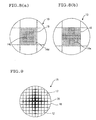
- partition walls 14c in the central part of the honeycomb segment 15 is formed to be thicker than partition walls 14d in the peripheral part as another preferable embodiment.
- partition walls 14e are formed to be thick in a cross form in each honeycomb segment 15 as still another preferable embodiment.
- the thickness of the partition wall in the central part of the honeycomb segment is preferably 1.02 to 1.5 times that of the partition wall in the peripheral part of the honeycomb segment. When the wall is thick 1.5 times, a air flow resistance of the whole honeycomb filter tends to increase.
- the thickness may be gradually increased toward the inside from a position of a contact 30 of an outer peripheral wall 18.
- the thickness of the partition wall 17 partitioning each through-hole 12 may be successively increased toward the inside from the outside.
- “being gradually increased” means that an average thickness of the partition wall 17 which partitions the through-hole 12 positioned in a peripheral side is increased.
- the thickness may be continuously changed as shown in Fig. 9, or the thickness may also be changed for each partition wall 17 which partitions one through-hole 12.
- the thickness of the partition wall of the honeycomb segment is in a range of preferably 50 to 2, 000 ⁇ m.
- the thickness of the partition wall is less than 50 ⁇ m, strength of the honeycomb segment becomes insufficient.
- the thickness exceeds 2000 ⁇ m, effective geometric surface area (GSA) of the honeycomb segment drops, and a pressure loss increases when the gas flows.
- the sectional area of the central part of the honeycomb segment is preferably 40 to 90%, further preferably 50 to 90% of that of the whole honeycomb segment in the section of the honeycomb filter perpendicular to the axial direction.
- a sectional shape of the section of the honeycomb filter perpendicular to the through-hole in the present invention may be various shapes such as a circle, an ellipse, and a lace track shape.
- honeycomb filter of the present invention an embodiment in which two or more honeycomb segments are combined/constituted may be employed.
- a material for the filter preferably contains one selected from the group consisting of SiC, Si 3 N 4 , alumina, mullite, aluminum titanate, zirconium phosphate, and lithium aluminum silicate as a main crystal phase from standpoints of strength, thermal resistance or the like, and SiC having a high thermal conductivity is especially preferable in that heat is easily discharged.
- the cell density of cells formed by the partition walls is preferably 6 to 2000 cells/square inch (0.9 to 311 cells/cm 2 ), further preferably 50 to 400 cells/square inch (7.8 to 62 cells/cm 2 ).
- the strength and effective geometric surface area (GSA) of the honeycomb segment become insufficient.
- the density exceeds 2000 cells/square inch (311 cells/cm 2 )
- the pressure loss increases when the gas flows.
- sectional shape of through-holes is preferably any of a triangle, a tetragon, a hexagon and a corrugated shape from the standpoint of production.
- a ceramic fiber, ceramic powder, or cement having heat resistance is preferably used alone, or they are mixed for use.
- an organic binder, an inorganic binder or the like may also be mixed and used.
- the dust-containing fluid flows into the honeycomb filter via the through-holes whose end portions on one end face side are not plugged.
- the fluid passes through porous partition walls having filterability, and enters the other through-holes that are not plugged on the side of the other end face of the honeycomb filter.
- the particulate matter in the dust-containing fluid is trapped by the partition walls when the fluid passes through the partition walls, and the purified fluid from which the particulate matter has been removed is discharged from the other end face of the honeycomb filter.
- a heating means such as a heater, the particulate matter is burnt/removed, and the filter function is regenerated.
- a metal having catalytic activity may be loaded on the honeycomb filter.
- the honeycomb filter of the present invention is loaded with a catalyst, for example, a metal having a catalytic activity when the present honeycomb filter is intended to use as a catalyst carrier for purifying exhaust gas emitted from a heat engine such as internal combustion engine or the like or from a burner such as boiler or the like, or for reforming liquid fuel or gaseous fuel.
- a catalyst for example, a metal having a catalytic activity
- Pt, Pd, Rh, K, Li and Na are mentioned, and it is preferred to load at least one kind of these on the honeycomb filter.
- the above-described preferable materials such as a silicon carbide powder are used.
- binders such as methyl cellulose and hydroxypropoxyl methylcellulose are added.
- a surface-active agent and water are added to prepare clay having plasticity. The clay is extruded to form honeycomb segments as shown, for example, in Figs. 4, 5, 8(a), 8(b), and 9.
- the outer peripheral surface of the honeycomb segment is coated with the bonding material having the same composition as that of the clay, and the honeycomb segments are bonded, assembled, and dried.
- the obtained assembled dry body is heated/degreased, for example, in a nitrogen atmosphere, and subsequently heated in an inert atmosphere such as Ar atmosphere so that the honeycomb filter of the present invention can be obtained.
- a plate formed by a bonding material in a predetermined thickness may be used, and a honeycomb segment may be bonded to another honeycomb segment by the plate and the bonding material.
- the end face of the honeycomb filter can be plugged with a raw material similar to that of the honeycomb segment.
- Catalyst may be loaded on the thus-produced honeycomb filter by a method ordinarily used by those skilled in the art, for example, by wash-coating a catalyst slurry on the honeycomb filter, and then conducting drying and firing.
- Regeneration limit was evaluated using a honeycomb filter having material characteristics such as a porosity of 45%, an average pore diameter of 10 ⁇ m, and a thermal conductivity of 40 W/mK and comprising a honeycomb structure of SiC having a diameter of 5.66 inches and a length of 6 inches and having a plugging depth of 3 mm.
- a predetermined amount of artificially produced soot was deposited on the honeycomb filter, and a high-temperature gas was introduced at 600°C, 2.3 Nm 3 /min to regenerate the filter (burn the soot). Thereafter, a limit soot amount in which any crack was not generated was set to a regeneration limit.
- a dimension of nine segments in Examples 4 to 7, Comparative Examples 2, 4 was basically 58 mm, and an outer peripheral segment was worked in a predetermined outer dimension in accordance with a product outer shape.
- the amount of deposited soot was 10 g/L, and a high-temperature gas having an O 2 concentration of 10% was introduced at 600°C, 0.7 Nm 3 /min to regenerate/burn the honeycomb filter.
- the results of measurement of a temperature distribution at the regeneration time in this case are shown in Fig. 10.
- r(m) denotes a length in a radial direction
- X(m) denotes a length in an axial direction
- lines shown in a graph are isothermal lines indicating a temperature distribution
- numeric values indicate temperatures of the isothermal lines (unit:°C).
- Example 1 Comparative Example Cell structure mil/cpi Additional structure Regeneration limit (g/L)
- Example 1 12/200 Central part additional plugged 100 cells 18
- Example 2 12/200 Wall thickness of central part 15 mil, radial direction 50 % length region 20
- Example 3 12/200 Central part 350 cpi, radial direction 50% length region 18
- Example 4 12/200 9 segments, bonding thickness 3 mm, segment central part in cross form, 7 cells added in width, 15/200 structure, cell thickness increase 20
- Example 5 12/200 9 segments, central segments 14/200, bonding thickness 3 mm 20
- Example 6 mm Comparative Example Cell structure mil/cpi Additional structure Regeneration limit
- Example 10 12/300 Wall thickness of central part 15 mil, radial direction 50% length region 22
- Example 11 12/300 Central part 350 cpi, radial direction 50% length region 16
- Example 12 12/300 9 segments, bonding thickness 3 mm, segment central part in cross shape, 7 cells in width, 15/200 structure, cell thickness increase 20
- Example 13 12/300 9 segments, central segment 14/200, bonding thickness 3 mm 18
- Example 14 12/300 9 segments, central segment peripheral bonding thickness 5 mm, other bonded portion 1 mm 16
- Example 16 12/300 Central part plugging depth 30 mm, peripheral part 3 mm, depth distribution proportional to
- the regeneration limit was evaluated with respect to honeycomb filters which were the same as those of Examples 1 to 8, Comparative Examples 1 to 4 except that cordierite was used as the material, cell structures with 12 mil/200 cpi, 12 mil/300 cpi were used, and the cell thickness of the honeycomb segment central part was increased to 15 mil.
- the results are shown in Table 3.
- SiC was used as a material
- 12 mil/200 cpi, 12 mil/300 cpi were used as a cell structure
- the cell thickness was increased in a predetermined area portion in the central part of a honeycomb segment as shown in FIG. 8(a)
- regeneration limits of Examples 19 to 25 were evaluated.
- the results of the evaluation of a uniform thickness are shown in Comparative Examples 12, 13.
- Example 17 12/200 9 segments, uniform bonding thickness 1 mm, segment central part 5 cell square 15/200 16
- Comparative Example 10 12/200 9 segments, uniform bonding thickness 1 mm 8
- Comparative Example 11 12/300 9 segments, uniform bonding thickness 1 mm 10
- Example 19 12/300 9 segments, uniform bonding thickness 1 mm, central part wall thickness 2% increase, central part area 90%
- Example 20 12/300 9 segments, uniform bonding thickness 1 mm, central part wall thickness 5% increase, central part area 90% 22
- a temperature rise is suppressed in a central part of the honeycomb filter or a central part of each honeycomb segment whose temperature tends to rise as compared with a peripheral part.
- a temperature difference between the central part and the peripheral part of honeycomb filter or between the central part and the peripheral part of each honeycomb segment is reduced, and a thermal stress generated in the honeycomb filter can be reduced.
- any crack can be inhibited from being generated in the honeycomb filter, and the filter has a superior effect that durability is remarkably superior.
Landscapes
- Physics & Mathematics (AREA)
- Geometry (AREA)
- Chemical & Material Sciences (AREA)
- Chemical Kinetics & Catalysis (AREA)
- Engineering & Computer Science (AREA)
- Combustion & Propulsion (AREA)
- Mechanical Engineering (AREA)
- General Engineering & Computer Science (AREA)
- Thermal Sciences (AREA)
- Filtering Materials (AREA)
- Processes For Solid Components From Exhaust (AREA)
- Porous Artificial Stone Or Porous Ceramic Products (AREA)
- Catalysts (AREA)
- Filtering Of Dispersed Particles In Gases (AREA)
Abstract
Description
| SiC material Example, Comparative Example | Cell structure mil/cpi | Additional structure | Regeneration limit (g/L) |
| Example 1 | 12/200 | Central part additional plugged 100 | 18 |
| Example 2 | 12/200 | Wall thickness of | 20 |
| Example 3 | 12/200 | Central part 350 cpi, radial direction 50 | 18 |
| Example 4 | 12/200 | 9 segments, bonding thickness 3 mm, segment central part in cross form, 7 cells added in width, 15/200 structure, | 20 |
| Example 5 | 12/200 | 9 segments, central segments 14/200, bonding thickness 3 | 20 |
| Example 6 mm. | 12/200 | 9 segments, central segment peripheral bonding thickness 5 another bonded portion 1 | 18 |
| Example 7 | 12/200 | 9 segments, central part segment thermal conductivity 1.5 times, bonding thickness 1 | 16 |
| Example 8 | 12/200 | Central | 18 |
| Comparative Example 1 | 12/200 | Plugging depth 3 | 12 |
| Comparative Example 2 | 12/200 9 | segments, uniform bonding thickness 1 | 10 |
| Comparative Example 3 | 15/200 | Plugging depth 3 | 12 |
| Comparative Example 4 | 14/200 | 9 segments, uniform bonding thickness 3 mm | 8 |
| SiC material Example, Comparative Example | Cell structure mil/cpi | Additional structure | Regeneration limit (g/L) |
| Example 9 | 12/300 | Central part additional <plugged 150 | 20 |
| Example 10 | 12/300 | Wall thickness of | 22 |
| Example 11 | 12/300 | Central part 350 cpi, radial direction 50 | 16 |
| Example 12 | 12/300 | 9 segments, bonding thickness 3 mm, segment central part in cross shape, 7 cells in width, 15/200 structure, | 20 |
| Example 13 | 12/300 | 9 segments, central segment 14/200, bonding thickness 3 | 18 |
| Example 14 | 12/300 | 9 segments, central segment peripheral bonding thickness 5 mm, other bonded portion 1 | 16 |
| Example 15 | 12/300 | 9 segments, central part segment thermal conductivity 1.5 times, | 18 |
| Example 16 | 12/300 | Central | 20 |
| Comparative Example 5 | 12/300 | Plugging depth 3 | 12 |
| Comparative Example 6 | 12/300 | 9 segments, uniform bonding thickness 1 | 12 |
| Comparative Example 7 | 15/300 | Plugging depth 3 | 10 |
| Comparative Example 8 | 14/300 | 9 segments, uniform bonding thickness 3 | 10 |
| Cordierite & SiC material Example, Comparative Example | Cell structure mil/cpi | Additional structure | Regeneration limit (g/L) |
| Example 17 | 12/200 | 9 segments, uniform bonding thickness 1 mm, segment central part 5 cell square 15/200 | 16 |
| Example 18 | 12/300 | 9 segments, uniform bonding thickness 1 mm, segment central part 5 cell square 15/300 | 16 |
| Comparative Example 10 | 12/200 9 | segments, uniform bonding thickness 1 mm | 8 |
| Comparative Example 11 | 12/300 9 | segments, uniform bonding thickness 1 mm | 10 |
| Example 19 | 12/300 | 9 segments, uniform bonding thickness 1 mm, central part wall thickness 2% increase, central part area 90% | 20 |
| Example 20 | 12/300 | 9 segments, uniform bonding thickness 1 mm, central part wall thickness 5% increase, central part area 90% | 22 |
| Example 21 | 12/300 | 9 segments, uniform bonding thickness 1 mm, central part wall thickness 5% increase, central part area 80% | 20 |
| Example 22 | 12/300 | 9 segments, uniform bonding thickness 1 mm, central part wall 50% increase, central part area 70% | 18 |
| Example 23 | 12/300 | 9 segments, uniform bonding thickness 1 mm, central part wall thickness 2% increase, central part area 70% | 18 |
| Example 24 | 15/200 | 9 segments, uniform bonding thickness 1 mm, central part wall thickness 2% increase, central part area 90% | 20 |
| Example 25 | 15/200 | 9 segments, uniform bonding thickness 1 mm, central part wall thickness 5% increase, central part area 80% | 20 |
| Comparative Example 12 | 12/300 | 9 segments, uniform bonding thickness 1 mm | 12 |
| Comparative Example 13 | 15/200 | 9 segments, uniform bonding thickness 1 mm | 12 |
Claims (17)
- A honeycomb filter for trapping particulate matter contained in dust-containing fluid,
the filter comprising a number of through-holes surrounded by partition walls and extending in an axial direction,
the partition walls having filterability, predetermined through-bales being plugged at one end, remaining through-holes being plugged at the other end,
wherein in a section of the honeycomb filter perpendicular to the axial direction, heat capacity in a central part of the honeycomb filter is higher than that in a peripheral part of the honeycomb filter. - The honeycomb filter according to claim 1, wherein in an end face of the honeycomb filter in the axial direction, a non-plugged through-hole end portion is plugged in the central part of the honeycomb filter.
- The honeycomb filter according to claim 1, wherein in the section of the honeycomb filter perpendicular to the axial direction, a thickness of the partition wall in the central part is set to be larger than that of the partition wall in the peripheral part.
- The honeycomb filter according to claim 1, wherein in the section of the honeycomb filter perpendicular to the axial direction, a cell density in the central part is set to be larger than that in the peripheral part.
- The honeycomb filter according to claim 1, wherein the plugging is performed in the honeycomb filter such that a plugging depth is large in the central part, and small in the peripheral part, so that a heat capacity in the central part of the honeycomb filter is set to be larger than that in the peripheral part.
- A honeycomb filter for trapping particulate matter contained in dust-containing fluid,
the filter comprising a number of through-holes surrounded by partition walls and extending in an axial direction,
the partition walls having filterability,
predetermined through-bales being plugged at one end, remaining through-holes being plugged at the other end,
wherein the honeycomb filter comprises an assembly of a plurality of honeycomb segments, and
in a section of each honeycomb segment perpendicular to the axial direction, a heat capacity of a central part of the honeycomb filter is higher than that of a peripheral part of the honeycomb filter. - The honeycomb filter according to claim 6, wherein the honeycomb filter comprises a plurality of the honeycomb segments bonded by a bonding material, and
in a section of the honeycomb filter perpendicular to the axial direction, a thickness of the partition wall of the honeycomb segment positioned in a central part of the honeycomb filter is set to be larger than that of the partition wall of the honeycomb segment positioned in a peripheral part. - The honeycomb filter according to claim 7, wherein the thickness of the partition wall in the central part of the honeycomb segment is set to 1.02 to 1.5 times that of the partition wall in the peripheral part of the honeycomb segment.
- The honeycomb filter according to any one of claims 6 to 8, wherein in the section of the honeycomb filter perpendicular to the axial direction, a sectional area of the central part of the honeycomb segment is set to 90% or less of that of the whole honeycomb segment.
- The honeycomb filter according to any one of claims 7 to 9, wherein in the section of the honeycomb filter perpendicular to the axial direction, the thickness of the partition wall is gradually reduced toward the peripheral part from the central part with respect to some or all of the partition walls of the honeycomb segment.
- The honeycomb filter according to any one of claims 6 to 10, wherein the honeycomb filter comprises a plurality of the honeycomb segments bonded by a bonding material, and
in the section of the honeycomb filter perpendicular to the axial direction, the bonding material of the honeycomb segment positioned in a central part of the honeycomb filter is formed to be thicker than that of the honeycomb segment positioned in a peripheral part. - The honeycomb filter according to any one of claims 6 to 11, wherein the honeycomb filter comprises a plurality of the honeycomb segments bonded by a bonding material, and
in the peripheral part in the section of the honeycomb filter perpendicular to the axial direction, a thermal conductivity of the honeycomb segment positioned in the central part of the honeycomb filter is higher than that of the honeycomb segment positioned. - The honeycomb filter according to any one of claims 6 to 12, wherein the plugging is performed in the honeycomb segment constituting the honeycomb filter such that a plugging depth is large in the central part of the honeycomb segment, and small in the peripheral part, so that a heat capacity of the central part of the honeycomb filter is set to be larger than that of the peripheral part.
- The honeycomb filter according to any one of claims 1 to 13, wherein a material of the filter contains one selected from the group consisting of SiC, Si3N4, alumina, mullite, aluminum titanate, zirconium phosphate, and lithium aluminum silicate as a main crystal phase.
- The honeycomb filter according to any one of claims 1 to 14, wherein a sectional shape of the through-hole is any of a triangle, a tetragon, a hexagon and a corrugated shape.
- The honeycomb filter according to any one of claims 6 to 15, wherein the honeycomb segment carries a catalyst.
- The honeycomb filter according to claim 16, wherein the catalyst contains at least one selected from the group consisting of Pt, Pd, Rh, K, Li, and Na.
Priority Applications (1)
| Application Number | Priority Date | Filing Date | Title |
|---|---|---|---|
| EP08010686A EP1983166B1 (en) | 2002-02-26 | 2003-02-25 | Honeycomb filter |
Applications Claiming Priority (3)
| Application Number | Priority Date | Filing Date | Title |
|---|---|---|---|
| JP2002050087 | 2002-02-26 | ||
| JP2002050087A JP4279497B2 (en) | 2002-02-26 | 2002-02-26 | Honeycomb filter |
| PCT/JP2003/002054 WO2003072913A1 (en) | 2002-02-26 | 2003-02-25 | Honeycomb filter |
Related Child Applications (1)
| Application Number | Title | Priority Date | Filing Date |
|---|---|---|---|
| EP08010686A Division EP1983166B1 (en) | 2002-02-26 | 2003-02-25 | Honeycomb filter |
Publications (3)
| Publication Number | Publication Date |
|---|---|
| EP1484483A1 true EP1484483A1 (en) | 2004-12-08 |
| EP1484483A4 EP1484483A4 (en) | 2005-09-28 |
| EP1484483B1 EP1484483B1 (en) | 2009-05-27 |
Family
ID=27764278
Family Applications (2)
| Application Number | Title | Priority Date | Filing Date |
|---|---|---|---|
| EP08010686A Expired - Lifetime EP1983166B1 (en) | 2002-02-26 | 2003-02-25 | Honeycomb filter |
| EP03707051A Expired - Lifetime EP1484483B1 (en) | 2002-02-26 | 2003-02-25 | Honeycomb filter |
Family Applications Before (1)
| Application Number | Title | Priority Date | Filing Date |
|---|---|---|---|
| EP08010686A Expired - Lifetime EP1983166B1 (en) | 2002-02-26 | 2003-02-25 | Honeycomb filter |
Country Status (8)
| Country | Link |
|---|---|
| US (1) | US7244284B2 (en) |
| EP (2) | EP1983166B1 (en) |
| JP (1) | JP4279497B2 (en) |
| KR (1) | KR100607478B1 (en) |
| AU (1) | AU2003211672A1 (en) |
| DE (1) | DE60327744D1 (en) |
| PL (1) | PL373704A1 (en) |
| WO (1) | WO2003072913A1 (en) |
Cited By (22)
| Publication number | Priority date | Publication date | Assignee | Title |
|---|---|---|---|---|
| EP1491248A4 (en) * | 2002-03-29 | 2006-05-17 | Ibiden Co Ltd | Ceramic filter and exhaust gas decontamination unit |
| EP1676622A4 (en) * | 2003-10-23 | 2006-09-27 | Ibiden Co Ltd | BODY STRUCTURE IN HONEYCOMB |
| WO2007057256A1 (en) * | 2005-11-18 | 2007-05-24 | Robert Bosch Gmbh | Filter element and filter for exhaust-gas aftertreatment |
| EP1737555A4 (en) * | 2004-04-23 | 2008-05-21 | Corning Inc | Diesel engine exhaust filters |
| EP1944073A1 (en) * | 2007-01-10 | 2008-07-16 | Robert Bosch GmbH | Particulate filter, in particular waste gas particulate filter for a combustion engine |
| WO2009023410A1 (en) * | 2007-08-14 | 2009-02-19 | General Electric Company | System and method for reducing particulate matter emission in diesel exhaust gas |
| EP1837493A3 (en) * | 2006-03-20 | 2009-04-08 | Ngk Insulators, Ltd. | Honeycomb structure |
| EP2065576A1 (en) * | 2007-11-28 | 2009-06-03 | Robert Bosch Gmbh | Exhaust gas treatment device and filter element to filter exhaust gases from a diesel combustion engine |
| FR2927118A1 (en) * | 2008-02-05 | 2009-08-07 | Renault Sas | Particle filter for exhaust pipe of supercharged internal combustion engine, has exhaust gas input channels situated close to central axis of monolithic hub and having circulation part whose length is shorter than that of output channels |
| EP1955751A4 (en) * | 2005-10-25 | 2009-12-23 | Ngk Insulators Ltd | Honeycomb filter |
| EP1974791A4 (en) * | 2005-12-26 | 2010-08-11 | Ngk Insulators Ltd | ALVEOLAR STRUCTURE AND METHOD FOR MANUFACTURING THE SAME |
| EP2243535A1 (en) * | 2009-03-27 | 2010-10-27 | NGK Insulators, Ltd. | Honeycomb structure and bonded type honeycomb structure |
| US7925431B2 (en) | 2007-08-14 | 2011-04-12 | General Electric Company | System and method for removing particulate matter from a diesel particulate filter |
| EP2133522A4 (en) * | 2007-03-27 | 2011-05-11 | Ngk Insulators Ltd | WATERPROOF HONEYCOMB STRUCTURE |
| EP2343113A1 (en) * | 2010-01-05 | 2011-07-13 | NGK Insulators, Ltd. | Honeycomb structure |
| EP2505247A1 (en) * | 2011-03-31 | 2012-10-03 | Ibiden Co., Ltd. | Honeycomb structured body |
| EP2119688A4 (en) * | 2007-02-05 | 2014-01-15 | Ngk Insulators Ltd | Honeycomb segments joined body for dpf and bonding material composition for the joined body |
| CN104066511A (en) * | 2012-01-27 | 2014-09-24 | 株式会社电装 | Honeycomb structure |
| EP2942097A1 (en) * | 2014-03-14 | 2015-11-11 | NGK Insulators, Ltd. | Plugged honeycomb structure |
| TWI581846B (en) * | 2014-12-31 | 2017-05-11 | 賴全裕 | Removable filter device |
| EP3339269A1 (en) * | 2016-12-20 | 2018-06-27 | Guizhou Huangdi Diesel Engine Cleaner Co., Ltd. | Cellular ceramic article with hybrid pore configuration |
| FR3081730A1 (en) * | 2018-05-29 | 2019-12-06 | Renault S.A.S | PARTICLE FILTER FOR INTERNAL COMBUSTION ENGINE OF AUTOMOTIVE ENGINE |
Families Citing this family (68)
| Publication number | Priority date | Publication date | Assignee | Title |
|---|---|---|---|---|
| JP4293753B2 (en) * | 2002-03-19 | 2009-07-08 | 日本碍子株式会社 | Honeycomb filter |
| EP1669123B1 (en) * | 2003-08-12 | 2010-10-06 | NGK Insulators, Ltd. | Ceramic filter |
| FR2865661B1 (en) * | 2004-02-04 | 2006-05-05 | Saint Gobain Ct Recherches | FILTRATION STRUCTURE, PARTICULARLY PARTICLE FILTER FOR EXHAUST GASES OF AN INTERNAL COMBUSTION ENGINE, AND ASSOCIATED EXHAUST LINE |
| JP4567674B2 (en) * | 2004-03-23 | 2010-10-20 | 日本碍子株式会社 | Ceramic filter |
| US20090288380A1 (en) * | 2004-07-12 | 2009-11-26 | Vincent Gleize | Filtration structure, in particular a particulate filter for the exhaust gases of an internal combustion engine, and associated exhaust line |
| FR2874964B1 (en) * | 2004-09-06 | 2009-05-29 | Saint Gobain Ct Recherches | EXHAUST GAS FILTRATION STRUCTURE OF AN INTERNAL COMBUSTION ENGINE AND EXHAUST LINE THEREFOR |
| JP2006110413A (en) * | 2004-10-12 | 2006-04-27 | Ngk Insulators Ltd | Honeycomb filter |
| KR100893514B1 (en) | 2005-05-23 | 2009-04-16 | 니뽄 가이시 가부시키가이샤 | Honeycomb structure |
| JP2007007559A (en) * | 2005-06-30 | 2007-01-18 | Hitachi Metals Ltd | Ceramic honeycomb filter |
| DE102006035053A1 (en) * | 2005-09-20 | 2007-03-22 | Robert Bosch Gmbh | Filter element and soot filter with geometrically similar channels |
| JPWO2007066671A1 (en) * | 2005-12-07 | 2009-05-21 | 日本碍子株式会社 | Honeycomb structure and manufacturing method thereof |
| EP1997556A4 (en) * | 2006-03-13 | 2012-12-19 | Ngk Insulators Ltd | A CATALYST STRUCTURE OF A HONEYCOMB |
| US7491373B2 (en) * | 2006-11-15 | 2009-02-17 | Corning Incorporated | Flow-through honeycomb substrate and exhaust after treatment system and method |
| WO2008105081A1 (en) * | 2007-02-28 | 2008-09-04 | Ibiden Co., Ltd. | Honeycomb filter |
| WO2008126433A1 (en) | 2007-03-30 | 2008-10-23 | Ngk Insulators, Ltd. | Honeycomb segment and honeycomb structure |
| US7806956B2 (en) * | 2007-08-09 | 2010-10-05 | Cummins Filtration Ip, Inc. | Tuning particulate filter performance through selective plugging and use of multiple particulate filters to reduce emissions and improve thermal robustness |
| WO2009066388A1 (en) * | 2007-11-21 | 2009-05-28 | Ibiden Co., Ltd. | Honeycomb structure and process for producing the same |
| JP4997090B2 (en) | 2007-12-26 | 2012-08-08 | 日本碍子株式会社 | Porous fired body and method for producing the same |
| JP2009154124A (en) * | 2007-12-27 | 2009-07-16 | Ngk Insulators Ltd | Partially unsealed dpf |
| JP5171279B2 (en) * | 2008-01-17 | 2013-03-27 | 京セラ株式会社 | Honeycomb structure, filter and exhaust gas treatment device |
| JP2009243274A (en) * | 2008-03-28 | 2009-10-22 | Mazda Motor Corp | Particulate filter |
| JP2010227923A (en) * | 2008-05-20 | 2010-10-14 | Ibiden Co Ltd | Honeycomb structure |
| SE532906C2 (en) * | 2008-09-23 | 2010-05-04 | Scania Cv Abp | Hydrolysis catalyst with greater channel cross-section in the peripheral part than in the central part and methods for hydrolysis of a urea |
| US20100154370A1 (en) * | 2008-12-22 | 2010-06-24 | Caterpillar Inc, | System and methods for particulate filter |
| JP5188433B2 (en) * | 2009-03-24 | 2013-04-24 | 日本碍子株式会社 | Honeycomb filter |
| JP5452961B2 (en) * | 2009-03-31 | 2014-03-26 | 日本碍子株式会社 | Honeycomb structure |
| JP5634983B2 (en) * | 2009-03-31 | 2014-12-03 | 日本碍子株式会社 | Honeycomb filter and manufacturing method thereof |
| US8444752B2 (en) * | 2009-08-31 | 2013-05-21 | Corning Incorporated | Particulate filters and methods of filtering particulate matter |
| JP5379039B2 (en) | 2010-02-16 | 2013-12-25 | 日本碍子株式会社 | Exhaust gas purification device and exhaust gas purification method |
| JP5563844B2 (en) | 2010-02-16 | 2014-07-30 | 日本碍子株式会社 | Exhaust gas purification device |
| JP5548470B2 (en) | 2010-02-16 | 2014-07-16 | 日本碍子株式会社 | Honeycomb catalyst body |
| JP5584487B2 (en) | 2010-02-16 | 2014-09-03 | 日本碍子株式会社 | Exhaust gas purification device |
| JP2011224973A (en) * | 2010-03-19 | 2011-11-10 | Ibiden Co Ltd | Honeycomb structure |
| WO2011114506A1 (en) | 2010-03-19 | 2011-09-22 | イビデン株式会社 | Honeycomb structure |
| JP5478309B2 (en) * | 2010-03-23 | 2014-04-23 | 日本碍子株式会社 | Honeycomb structure |
| EP2554236B1 (en) * | 2010-03-31 | 2020-07-08 | NGK Insulators, Ltd. | Honeycomb filter |
| US9856177B2 (en) | 2010-05-28 | 2018-01-02 | Corning Incorporated | Cordierite porous ceramic honeycomb articles |
| US9334191B2 (en) | 2010-05-28 | 2016-05-10 | Corning Incorporated | Methods for forming ceramic honeycomb articles |
| US8273315B2 (en) * | 2010-08-09 | 2012-09-25 | Ford Global Technologies, Llc | Engine emission control system |
| JP5601957B2 (en) * | 2010-10-12 | 2014-10-08 | 住友化学株式会社 | Aluminum titanate honeycomb structure |
| EP2684590B1 (en) * | 2011-03-10 | 2017-09-13 | NGK Insulators, Ltd. | Honeycomb structure |
| US8440155B2 (en) | 2011-08-19 | 2013-05-14 | Corning Incorporated | Flow modulating substrates for early light-off |
| US9168479B2 (en) * | 2012-08-13 | 2015-10-27 | Ngk Insulators, Ltd. | Plugged honeycomb structure |
| US9238190B2 (en) * | 2012-08-13 | 2016-01-19 | Ngk Insulators, Ltd. | Plugged honeycomb structure |
| JP5708670B2 (en) * | 2013-01-18 | 2015-04-30 | 株式会社デンソー | Honeycomb structure |
| JP5888259B2 (en) * | 2013-02-13 | 2016-03-16 | トヨタ自動車株式会社 | Catalytic converter |
| WO2014169902A2 (en) * | 2013-04-16 | 2014-10-23 | Rauschert Kloster Veilsdorf Gmbh | Filter elements and a filter device having at least one filter element |
| EP3127611B1 (en) * | 2014-03-31 | 2018-12-26 | NGK Insulators, Ltd. | Honeycomb structure |
| JP6485162B2 (en) | 2014-07-24 | 2019-03-20 | 株式会社デンソー | Exhaust gas purification filter |
| JP2016125797A (en) * | 2015-01-08 | 2016-07-11 | 東京窯業株式会社 | Honeycomb structure |
| JP6934702B2 (en) * | 2015-03-27 | 2021-09-15 | 株式会社デンソー | Exhaust gas purification filter |
| JP6530680B2 (en) * | 2015-09-02 | 2019-06-12 | 日本碍子株式会社 | Plugged honeycomb structure and plugged honeycomb segment |
| US9932873B2 (en) | 2015-09-18 | 2018-04-03 | Ngk Insulators, Ltd. | Exhaust gas purifying device |
| JP6635819B2 (en) | 2016-02-16 | 2020-01-29 | 日本碍子株式会社 | Honeycomb structure |
| JP6639977B2 (en) | 2016-03-23 | 2020-02-05 | 日本碍子株式会社 | Honeycomb filter |
| JP6639978B2 (en) | 2016-03-23 | 2020-02-05 | 日本碍子株式会社 | Honeycomb filter |
| JP6691811B2 (en) | 2016-05-02 | 2020-05-13 | 日本碍子株式会社 | Plugged honeycomb structure and method for forming plugged honeycomb structure |
| JP6767235B2 (en) * | 2016-10-19 | 2020-10-14 | 日本碍子株式会社 | Sealed honeycomb structure |
| JP6829979B2 (en) * | 2016-10-19 | 2021-02-17 | 日本碍子株式会社 | Sealed honeycomb structure |
| JP6862245B2 (en) | 2017-03-30 | 2021-04-21 | 日本碍子株式会社 | Honeycomb filter |
| JP2018167200A (en) | 2017-03-30 | 2018-11-01 | 日本碍子株式会社 | Honeycomb filter |
| JP7193963B2 (en) | 2018-09-27 | 2022-12-21 | 日本碍子株式会社 | honeycomb filter |
| JP7202236B2 (en) * | 2019-03-29 | 2023-01-11 | 日本碍子株式会社 | honeycomb filter |
| JP7232103B2 (en) * | 2019-03-29 | 2023-03-02 | 日本碍子株式会社 | honeycomb filter |
| JP7217191B2 (en) * | 2019-03-29 | 2023-02-02 | 日本碍子株式会社 | honeycomb filter |
| JP2023017750A (en) * | 2021-07-26 | 2023-02-07 | 株式会社プロテリアル | Ceramic honeycomb structure for methanation reaction catalyst carrier and method for manufacturing the same |
| JP7748321B2 (en) * | 2022-03-29 | 2025-10-02 | 日本碍子株式会社 | Honeycomb Filter |
| CN118188109A (en) * | 2022-12-14 | 2024-06-14 | 日本碍子株式会社 | Honeycomb filter |
Family Cites Families (31)
| Publication number | Priority date | Publication date | Assignee | Title |
|---|---|---|---|---|
| US3853485A (en) * | 1972-12-11 | 1974-12-10 | Corning Glass Works | Core member for catalytic oxidation converter |
| GB8420149D0 (en) | 1984-08-08 | 1984-09-12 | Ici Plc | Chemical process |
| JPS6147420U (en) * | 1984-08-31 | 1986-03-29 | トヨタ自動車株式会社 | Honeycomb filter for collecting diesel particulate matter |
| DE3444472C1 (en) * | 1984-12-06 | 1986-02-13 | Daimler-Benz Ag, 7000 Stuttgart | Exhaust filter for diesel engines |
| JPH0356354Y2 (en) * | 1986-04-08 | 1991-12-18 | ||
| JPH02112919A (en) | 1988-10-22 | 1990-04-25 | Mitsuhiro Kanao | Nozzle with valve |
| JPH0631133Y2 (en) * | 1988-10-31 | 1994-08-22 | いすゞ自動車株式会社 | Exhaust gas purification filter |
| JPH0710024Y2 (en) * | 1989-02-27 | 1995-03-08 | 日産ディーゼル工業株式会社 | Structure of the particulate filter |
| JPH0444420A (en) | 1990-06-12 | 1992-02-14 | Hitachi Ltd | Logic circuit |
| JPH088243Y2 (en) * | 1990-08-22 | 1996-03-06 | 日産ディーゼル工業株式会社 | Particulate filter |
| US5108685A (en) * | 1990-12-17 | 1992-04-28 | Corning Incorporated | Method and apparatus for forming an article with multi-cellular densities and/or geometries |
| JPH06241017A (en) | 1993-02-12 | 1994-08-30 | Nissan Diesel Motor Co Ltd | Trap filter device for particulate |
| JPH0742534A (en) * | 1993-07-27 | 1995-02-10 | Toyota Motor Corp | Exhaust particulate removal device for diesel engine |
| JP3390055B2 (en) | 1993-08-18 | 2003-03-24 | イビデン株式会社 | Exhaust gas purification device |
| JP3121497B2 (en) | 1994-07-14 | 2000-12-25 | イビデン株式会社 | Ceramic structure |
| JP3589308B2 (en) | 1994-07-14 | 2004-11-17 | イビデン株式会社 | Exhaust gas purification device |
| JP3012167B2 (en) * | 1995-04-12 | 2000-02-21 | 日本碍子株式会社 | Exhaust gas purification filter and exhaust gas purification device using the same |
| EP0745416B1 (en) * | 1995-06-02 | 2003-09-17 | Corning Incorporated | Device for removal of contaminants from fluid streams |
| KR100362211B1 (en) * | 1995-12-29 | 2003-06-09 | 에스케이 주식회사 | Diesel vehicle particulate matter removal device |
| EP0796830B1 (en) * | 1996-03-23 | 2002-08-21 | Thomas Josef Heimbach GmbH & Co. | Porous permeable body and method for its preparation |
| JPH1059784A (en) | 1996-08-13 | 1998-03-03 | Ishikawajima Harima Heavy Ind Co Ltd | Ceramic honeycomb structure |
| DE19938038A1 (en) * | 1998-09-14 | 2000-05-04 | Ford Global Tech Inc | Exhaust gas treatment device with varying cell density |
| ES2341274T3 (en) * | 1999-09-29 | 2010-06-17 | Ibiden Co., Ltd. | PANAL FILTER AND CERAMIC FILTER ASSEMBLY. |
| JP4049501B2 (en) * | 2000-01-24 | 2008-02-20 | 日本碍子株式会社 | Ceramic structure |
| JP2001241316A (en) * | 2000-02-29 | 2001-09-07 | Ibiden Co Ltd | Exhaust gas purifying device, filter used therein and exhaust gas purifying method |
| US6673414B2 (en) | 2000-12-20 | 2004-01-06 | Corning Incorporated | Diesel particulate filters |
| JP5052717B2 (en) * | 2001-05-02 | 2012-10-17 | 日本碍子株式会社 | Honeycomb structure, and honeycomb filter and converter system using the same |
| JP2003010616A (en) | 2001-06-29 | 2003-01-14 | Ngk Insulators Ltd | Honeycomb structure |
| JP4246425B2 (en) * | 2001-10-15 | 2009-04-02 | 日本碍子株式会社 | Honeycomb filter |
| EP1312776A3 (en) * | 2001-11-16 | 2004-05-12 | Isuzu Motors Limited | Exhaust gas purification system |
| FR2833857B1 (en) * | 2001-12-20 | 2004-10-15 | Saint Gobain Ct Recherches | FILTER BODY COMPRISING A PLURALITY OF FILTER BLOCKS, IN PARTICULAR FOR A PARTICLE FILTER |
-
2002
- 2002-02-26 JP JP2002050087A patent/JP4279497B2/en not_active Expired - Lifetime
-
2003
- 2003-02-25 EP EP08010686A patent/EP1983166B1/en not_active Expired - Lifetime
- 2003-02-25 EP EP03707051A patent/EP1484483B1/en not_active Expired - Lifetime
- 2003-02-25 PL PL03373704A patent/PL373704A1/en not_active Application Discontinuation
- 2003-02-25 KR KR1020047011741A patent/KR100607478B1/en not_active Expired - Fee Related
- 2003-02-25 WO PCT/JP2003/002054 patent/WO2003072913A1/en not_active Ceased
- 2003-02-25 US US10/500,969 patent/US7244284B2/en not_active Expired - Lifetime
- 2003-02-25 DE DE60327744T patent/DE60327744D1/en not_active Expired - Lifetime
- 2003-02-25 AU AU2003211672A patent/AU2003211672A1/en not_active Abandoned
Cited By (30)
| Publication number | Priority date | Publication date | Assignee | Title |
|---|---|---|---|---|
| EP1491248A4 (en) * | 2002-03-29 | 2006-05-17 | Ibiden Co Ltd | Ceramic filter and exhaust gas decontamination unit |
| US7510588B2 (en) | 2002-03-29 | 2009-03-31 | Ibiden Co., Ltd. | Ceramic filter and exhaust gas decontamination unit |
| EP1676622A4 (en) * | 2003-10-23 | 2006-09-27 | Ibiden Co Ltd | BODY STRUCTURE IN HONEYCOMB |
| US7517502B2 (en) | 2003-10-23 | 2009-04-14 | Ibiden Co., Ltd. | Honeycomb structural body |
| EP1737555A4 (en) * | 2004-04-23 | 2008-05-21 | Corning Inc | Diesel engine exhaust filters |
| EP1955751A4 (en) * | 2005-10-25 | 2009-12-23 | Ngk Insulators Ltd | Honeycomb filter |
| WO2007057256A1 (en) * | 2005-11-18 | 2007-05-24 | Robert Bosch Gmbh | Filter element and filter for exhaust-gas aftertreatment |
| EP1974791A4 (en) * | 2005-12-26 | 2010-08-11 | Ngk Insulators Ltd | ALVEOLAR STRUCTURE AND METHOD FOR MANUFACTURING THE SAME |
| EP1837493A3 (en) * | 2006-03-20 | 2009-04-08 | Ngk Insulators, Ltd. | Honeycomb structure |
| EP1944073A1 (en) * | 2007-01-10 | 2008-07-16 | Robert Bosch GmbH | Particulate filter, in particular waste gas particulate filter for a combustion engine |
| EP2119688A4 (en) * | 2007-02-05 | 2014-01-15 | Ngk Insulators Ltd | Honeycomb segments joined body for dpf and bonding material composition for the joined body |
| EP2133522A4 (en) * | 2007-03-27 | 2011-05-11 | Ngk Insulators Ltd | WATERPROOF HONEYCOMB STRUCTURE |
| US7972677B2 (en) | 2007-03-27 | 2011-07-05 | Ngk Insulators, Ltd. | Plugged honeycomb structure |
| US7925431B2 (en) | 2007-08-14 | 2011-04-12 | General Electric Company | System and method for removing particulate matter from a diesel particulate filter |
| US8240138B2 (en) | 2007-08-14 | 2012-08-14 | General Electric Company | System and method for reducing particulate matter emission in diesel exhaust gas |
| US8468809B2 (en) | 2007-08-14 | 2013-06-25 | General Electric Company | System and method for removing particulate matter from a diesel particulate filter |
| WO2009023410A1 (en) * | 2007-08-14 | 2009-02-19 | General Electric Company | System and method for reducing particulate matter emission in diesel exhaust gas |
| EP2065576A1 (en) * | 2007-11-28 | 2009-06-03 | Robert Bosch Gmbh | Exhaust gas treatment device and filter element to filter exhaust gases from a diesel combustion engine |
| FR2927118A1 (en) * | 2008-02-05 | 2009-08-07 | Renault Sas | Particle filter for exhaust pipe of supercharged internal combustion engine, has exhaust gas input channels situated close to central axis of monolithic hub and having circulation part whose length is shorter than that of output channels |
| US8999479B2 (en) | 2009-03-27 | 2015-04-07 | Ngk Insulators, Ltd. | Honeycomb structure and bonded type honeycomb structure |
| EP2243535A1 (en) * | 2009-03-27 | 2010-10-27 | NGK Insulators, Ltd. | Honeycomb structure and bonded type honeycomb structure |
| EP2343113A1 (en) * | 2010-01-05 | 2011-07-13 | NGK Insulators, Ltd. | Honeycomb structure |
| US8663356B2 (en) | 2010-01-05 | 2014-03-04 | Ngk Insulators, Ltd. | Honeycomb structure |
| EP2505247A1 (en) * | 2011-03-31 | 2012-10-03 | Ibiden Co., Ltd. | Honeycomb structured body |
| CN104066511A (en) * | 2012-01-27 | 2014-09-24 | 株式会社电装 | Honeycomb structure |
| CN104066511B (en) * | 2012-01-27 | 2016-06-01 | 株式会社电装 | honeycomb structure |
| EP2942097A1 (en) * | 2014-03-14 | 2015-11-11 | NGK Insulators, Ltd. | Plugged honeycomb structure |
| TWI581846B (en) * | 2014-12-31 | 2017-05-11 | 賴全裕 | Removable filter device |
| EP3339269A1 (en) * | 2016-12-20 | 2018-06-27 | Guizhou Huangdi Diesel Engine Cleaner Co., Ltd. | Cellular ceramic article with hybrid pore configuration |
| FR3081730A1 (en) * | 2018-05-29 | 2019-12-06 | Renault S.A.S | PARTICLE FILTER FOR INTERNAL COMBUSTION ENGINE OF AUTOMOTIVE ENGINE |
Also Published As
| Publication number | Publication date |
|---|---|
| EP1983166A1 (en) | 2008-10-22 |
| JP4279497B2 (en) | 2009-06-17 |
| EP1484483A4 (en) | 2005-09-28 |
| AU2003211672A1 (en) | 2003-09-09 |
| US20040258582A1 (en) | 2004-12-23 |
| EP1484483B1 (en) | 2009-05-27 |
| US7244284B2 (en) | 2007-07-17 |
| KR100607478B1 (en) | 2006-08-02 |
| EP1983166B1 (en) | 2012-08-01 |
| JP2003254034A (en) | 2003-09-10 |
| KR20040083099A (en) | 2004-09-30 |
| WO2003072913A1 (en) | 2003-09-04 |
| PL373704A1 (en) | 2005-09-05 |
| DE60327744D1 (en) | 2009-07-09 |
Similar Documents
| Publication | Publication Date | Title |
|---|---|---|
| US7244284B2 (en) | Honeycomb filter | |
| US7138002B2 (en) | Honeycomb structure and process for production thereof | |
| US7384441B2 (en) | Honeycomb filter | |
| US6984253B2 (en) | Honeycomb filter | |
| US7169203B2 (en) | Honeycomb structure | |
| US7179516B2 (en) | Honeycomb filter | |
| US7294316B2 (en) | Honeycomb structure, honeycomb filter and processes for the production thereof | |
| US8999479B2 (en) | Honeycomb structure and bonded type honeycomb structure | |
| JP2004270569A (en) | Honeycomb structure | |
| US20060168908A1 (en) | Honeycomb structural body and method of manufacturing the same | |
| US10625195B2 (en) | Honeycomb filter | |
| JP5351678B2 (en) | Honeycomb structure | |
| US10105696B2 (en) | Honeycomb structure | |
| US8236404B2 (en) | Honeycomb structure |
Legal Events
| Date | Code | Title | Description |
|---|---|---|---|
| PUAI | Public reference made under article 153(3) epc to a published international application that has entered the european phase |
Free format text: ORIGINAL CODE: 0009012 |
|
| 17P | Request for examination filed |
Effective date: 20040803 |
|
| AK | Designated contracting states |
Kind code of ref document: A1 Designated state(s): AT BE BG CH CY CZ DE DK EE ES FI FR GB GR HU IE IT LI LU MC NL PT SE SI SK TR |
|
| AX | Request for extension of the european patent |
Extension state: AL LT LV MK RO |
|
| A4 | Supplementary search report drawn up and despatched |
Effective date: 20050816 |
|
| RIC1 | Information provided on ipc code assigned before grant |
Ipc: B01D 46/24 20060101ALN20080908BHEP Ipc: F01N 3/02 20060101AFI20080908BHEP |
|
| GRAP | Despatch of communication of intention to grant a patent |
Free format text: ORIGINAL CODE: EPIDOSNIGR1 |
|
| GRAS | Grant fee paid |
Free format text: ORIGINAL CODE: EPIDOSNIGR3 |
|
| GRAA | (expected) grant |
Free format text: ORIGINAL CODE: 0009210 |
|
| AK | Designated contracting states |
Kind code of ref document: B1 Designated state(s): DE FR |
|
| REF | Corresponds to: |
Ref document number: 60327744 Country of ref document: DE Date of ref document: 20090709 Kind code of ref document: P |
|
| PLBE | No opposition filed within time limit |
Free format text: ORIGINAL CODE: 0009261 |
|
| STAA | Information on the status of an ep patent application or granted ep patent |
Free format text: STATUS: NO OPPOSITION FILED WITHIN TIME LIMIT |
|
| 26N | No opposition filed |
Effective date: 20100302 |
|
| REG | Reference to a national code |
Ref country code: FR Ref legal event code: PLFP Year of fee payment: 13 |
|
| PGFP | Annual fee paid to national office [announced via postgrant information from national office to epo] |
Ref country code: FR Payment date: 20150210 Year of fee payment: 13 |
|
| REG | Reference to a national code |
Ref country code: FR Ref legal event code: ST Effective date: 20161028 |
|
| PG25 | Lapsed in a contracting state [announced via postgrant information from national office to epo] |
Ref country code: FR Free format text: LAPSE BECAUSE OF NON-PAYMENT OF DUE FEES Effective date: 20160229 |
|
| PGFP | Annual fee paid to national office [announced via postgrant information from national office to epo] |
Ref country code: DE Payment date: 20220105 Year of fee payment: 20 |
|
| REG | Reference to a national code |
Ref country code: DE Ref legal event code: R071 Ref document number: 60327744 Country of ref document: DE |