JP2016125797A - Honeycomb structure - Google Patents
Honeycomb structure Download PDFInfo
- Publication number
- JP2016125797A JP2016125797A JP2015002171A JP2015002171A JP2016125797A JP 2016125797 A JP2016125797 A JP 2016125797A JP 2015002171 A JP2015002171 A JP 2015002171A JP 2015002171 A JP2015002171 A JP 2015002171A JP 2016125797 A JP2016125797 A JP 2016125797A
- Authority
- JP
- Japan
- Prior art keywords
- honeycomb structure
- cell density
- tube
- outer peripheral
- segments
- Prior art date
- Legal status (The legal status is an assumption and is not a legal conclusion. Google has not performed a legal analysis and makes no representation as to the accuracy of the status listed.)
- Pending
Links
Images
Classifications
-
- Y—GENERAL TAGGING OF NEW TECHNOLOGICAL DEVELOPMENTS; GENERAL TAGGING OF CROSS-SECTIONAL TECHNOLOGIES SPANNING OVER SEVERAL SECTIONS OF THE IPC; TECHNICAL SUBJECTS COVERED BY FORMER USPC CROSS-REFERENCE ART COLLECTIONS [XRACs] AND DIGESTS
- Y02—TECHNOLOGIES OR APPLICATIONS FOR MITIGATION OR ADAPTATION AGAINST CLIMATE CHANGE
- Y02E—REDUCTION OF GREENHOUSE GAS [GHG] EMISSIONS, RELATED TO ENERGY GENERATION, TRANSMISSION OR DISTRIBUTION
- Y02E60/00—Enabling technologies; Technologies with a potential or indirect contribution to GHG emissions mitigation
- Y02E60/14—Thermal energy storage
Abstract
Description
本発明は、ラジアントチューブヒータのチューブ内に配置されるハニカム構造体に関するものである。 The present invention relates to a honeycomb structure disposed in a tube of a radiant tube heater.
ラジアントチューブヒータは、金属やセラミック製のチューブ内にバーナ等で加熱した空気等の流体を流通させてチューブを加熱し、加熱されたチューブからの放射熱によって被加熱物を間接的に加熱する加熱装置である。一般的に、ラジアントチューブヒータは、鉄材の浸炭処理を行う浸炭炉や、焼鈍処理を行う焼鈍炉など、炉内の雰囲気を制御する加熱炉に使用されている。 A radiant tube heater heats a tube by circulating a fluid such as air heated by a burner or the like in a metal or ceramic tube, and indirectly heats the object to be heated by radiant heat from the heated tube. Device. In general, the radiant tube heater is used in a heating furnace that controls the atmosphere in the furnace, such as a carburizing furnace that performs a carburizing process of an iron material or an annealing furnace that performs an annealing process.
しかしながら、加熱された流体(以下、「加熱流体」と称する)がチューブ内を流通する際、チューブの内壁面の近傍は摩擦抵抗が働き流れ難いため、加熱流体はチューブの中心近くを流通しやすく、チューブに熱が伝わりにくい。また、チューブの内壁面の近傍を流通していく加熱流体の温度は、内壁面との熱交換により低下していく。このため、バーナ等の加熱源からの距離が大きくなるに従い、チューブの温度が低下するという問題があった。 However, when heated fluid (hereinafter referred to as “heated fluid”) flows through the tube, the frictional resistance acts and hardly flows near the inner wall surface of the tube, so that the heated fluid easily flows near the center of the tube. , Heat is not easily transmitted to the tube. In addition, the temperature of the heating fluid that flows in the vicinity of the inner wall surface of the tube decreases due to heat exchange with the inner wall surface. For this reason, there existed a problem that the temperature of a tube fell as the distance from heating sources, such as a burner, became large.
この問題を解決することを意図して、加熱流体からチューブへの伝熱を促進させる伝熱促進体を、チューブ内に配置する提案がなされている(特許文献1,2参照)。特許文献1の伝熱促進体は、軽量耐火物製の四枚の板状の仕切部を有する断面十字形の形状を有しており、伝熱促進体の軸方向をチューブの軸方向と平行にして配置するものである。特許文献2の伝熱促進体は、セラミックス等で形成された螺旋形状の案内羽根を有しており、螺旋の軸方向をチューブの軸方向と平行にして配置するものである。
In order to solve this problem, proposals have been made to arrange a heat transfer promoting body for promoting heat transfer from a heated fluid to the tube (see Patent Documents 1 and 2). The heat transfer promoting body of Patent Document 1 has a cross-shaped cross section having four plate-like partitions made of lightweight refractory, and the axial direction of the heat transfer promoting body is parallel to the axial direction of the tube. Is to be arranged. The heat transfer promoting body of
しかしながら、特許文献1及び特許文献2の伝熱促進体は共に、その表面積は大きくない。このため、加熱流体と接触する面積も大きくなく、加熱流体から伝熱促進体に熱が伝わりにくい。また、伝熱促進体からチューブに放射される熱量は表面積に依存するため、伝熱促進体からチューブにも熱が伝わりにくい。
However, the heat transfer promoting bodies of Patent Document 1 and
そこで、ハニカム構造体を伝熱促進体として用いることが提案されている(特許文献3参照)。ハニカム構造体は表面積が大きいため、特許文献3の伝熱促進体において加熱流体と接触する面積は、特許文献1及び特許文献2の伝熱促進体よりも大きい利点がある。しかしながら、上記のように加熱流体はチューブの中心近くを流通しやすいため、チューブ内に配置されたハニカム構造体においても、加熱流体はハニカム構造体の中心部分を流通し易い。このため、特許文献3の発明では、ハニカム構造体の表面積の大きさを十分に活かすことができず、伝熱の効率は高いと言えるものではなかった。
Thus, it has been proposed to use a honeycomb structure as a heat transfer promoting body (see Patent Document 3). Since the honeycomb structure has a large surface area, the area in contact with the heating fluid in the heat transfer promoting body of Patent Document 3 is larger than that of the heat transfer promoting body of Patent Document 1 and
そこで、本発明は、上記の実情に鑑み、ラジアントチューブヒータのチューブ内に配置されることにより、加熱流体からチューブへ効率的に伝熱することができるハニカム構造体の提供を、課題とするものである。 Therefore, in view of the above situation, the present invention has an object to provide a honeycomb structure that can be efficiently transferred from a heating fluid to a tube by being arranged in the tube of a radiant tube heater. It is.
上記の課題を解決するため、本発明にかかるハニカム構造体は、「ラジアントチューブヒータのチューブ内に配置される、単一の軸方向に延びて列設された隔壁により区画された複数のセルを備えるハニカム構造体であって、前記軸方向に直交した断面において、中心部のセル密度が外周部のセル密度よりも大きい」ものである。 In order to solve the above-described problems, a honeycomb structure according to the present invention has a structure in which a plurality of cells defined by partition walls arranged in a single axial direction and arranged in a tube of a radiant tube heater are arranged. The honeycomb structure is provided with a cell density in the central portion larger than that in the outer peripheral portion in the cross section orthogonal to the axial direction.
「ラジアントチューブヒータ」の「チューブ」は、ガスバーナや電気ヒータ等を加熱源とする加熱流体を内部に流通させる構成であり、U字形状、L字形状、T字形状、ストレート形状等の様々の形状とすることができる。更に、流体が排出される側の端部に熱交換器を設け、チューブに流入させる流体を予熱する構成としても良い。 The “tube” of the “radiant tube heater” has a configuration in which a heating fluid using a gas burner, an electric heater or the like as a heating source is circulated inside, and has various shapes such as a U shape, an L shape, a T shape, and a straight shape. It can be a shape. Furthermore, it is good also as a structure which provides a heat exchanger in the edge part by which the fluid is discharged | emitted, and preheats the fluid which flows in into a tube.
「ハニカム構造体」の材質は、高温の環境に長時間曝されるため、炭化珪素、アルミナ、ムライト、コージェライト等のセラミックスが好ましく、その中でも熱伝導率が高いことから炭化珪素が特に好ましい。また、ハニカム構造体の形状は、特に限定されるものではなく、外形は円柱状や多角柱状とすることができ、セルの断面形状は四角形、三角形、六角形等の多角形とすることができる。 The material of the “honeycomb structure” is preferably ceramics such as silicon carbide, alumina, mullite, cordierite and the like because it is exposed to a high temperature environment for a long time, and silicon carbide is particularly preferable because of its high thermal conductivity. In addition, the shape of the honeycomb structure is not particularly limited, and the outer shape can be a cylindrical shape or a polygonal column shape, and the cell cross-sectional shape can be a polygon such as a quadrangle, a triangle, a hexagon, or the like. .
「中心部のセル密度が外周部のセル密度よりも大きい」ハニカム構造体は、セル密度がそのように分布した型を用いた押出成形や、それぞれのセル密度は単一の大きさであるが互いにセル密度の相違するハニカム構造のセグメントを、複数接合させて形成することができる。 “The cell density in the central part is larger than the cell density in the outer periphery”, the honeycomb structure is extruded using a mold in which the cell density is distributed as such, and each cell density is a single size. A plurality of honeycomb structure segments having different cell densities can be joined together.
また、「中心部」と「外周部」の間に、セル密度が中心部よりも小さく、外周部よりも大きい「中間部」を備える構成とすることができる。この場合、中間部は更に、中心部側より外周部側でセル密度が小さい複数の部分で形成される構成とすることができる。 Moreover, it can be set as the structure provided with an "intermediate part" whose cell density is smaller than a center part and larger than an outer periphery part between "center part" and "outer periphery part". In this case, the intermediate portion can be further formed of a plurality of portions having a cell density smaller on the outer peripheral portion side than on the central portion side.
本構成のハニカム構造体では、セル密度が外周部よりも中心部で大きいため、外周部と比較して中心部において加熱流体が流れにくい。このため、外周部に流入する加熱流体の量が増え、従来のハニカム構造体では中心部に偏って流通していた加熱流体を、ハニカム構造体の全体に、均一な流れに近付けて流通させることができる。これにより、ハニカム構造体の大きな表面積が十分に活用され、加熱流体の有する熱を効率的にチューブへ伝えることができる。 In the honeycomb structure of this configuration, since the cell density is larger in the center than in the outer periphery, the heating fluid is less likely to flow in the center than in the outer periphery. For this reason, the amount of the heating fluid flowing into the outer peripheral portion is increased, and the heating fluid that has been distributed in the center of the conventional honeycomb structure is distributed close to a uniform flow throughout the honeycomb structure. Can do. Thereby, the large surface area of the honeycomb structure is fully utilized, and the heat of the heating fluid can be efficiently transmitted to the tube.
本発明にかかるハニカム構造体は、上記構成に加えて、「単一の方向に延びて列設された隔壁により区画された複数のセルを備えるハニカム構造を有するセグメントが複数接合されて形成されており、前記中心部及び前記外周部は、それぞれセル密度が単一の前記セグメントによって形成されている」ものとすることができる。 In addition to the above-described structure, the honeycomb structure according to the present invention is formed by joining a plurality of segments having a honeycomb structure including a plurality of cells partitioned by partition walls extending in a single direction. The central portion and the outer peripheral portion are each formed by the segments having a single cell density.
「セグメント」の形状は特に限定されるものではなく、ハニカム構造体の形状に応じて、四角柱、三角柱等の多角柱状の外形とすることができる。また、中心部及び外周部が、それぞれセル密度が単一のセグメントで形成されるものであれば、セグメントの個数は限定されない。なお、上記のように中心部及び外周部に加えて中間部を備える場合は、セル密度の異なるセグメントの三種以上によってハニカム構造体が形成される。 The shape of the “segment” is not particularly limited, and may be an outer shape of a polygonal column such as a quadrangular prism or a triangular prism depending on the shape of the honeycomb structure. In addition, the number of segments is not limited as long as the central portion and the outer peripheral portion are each formed of a single cell density. When the intermediate portion is provided in addition to the center portion and the outer peripheral portion as described above, the honeycomb structure is formed by three or more types of segments having different cell densities.
本構成のハニカム構造体によれば、セル密度が単一である従来のハニカム構造体をセグメントとして、本構成のハニカム構造体を容易に形成することができる。このため、新たに設備を導入する必要がなくコストを抑えて本構成のハニカム構造体を製造することができる。また、ラジアントチューブヒータのチューブの内径に応じて、断面積の大きいハニカム構造体を容易に形成することができる。これにより、大型のラジアントチューブヒータであっても、ハニカム構造体の断面積をチューブの内径に応じた大きさとすることにより、加熱流体の熱をチューブへ効率的に伝熱することができる。 According to the honeycomb structure of the present configuration, the honeycomb structure of the present configuration can be easily formed using the conventional honeycomb structure having a single cell density as a segment. For this reason, it is not necessary to introduce new equipment, and the honeycomb structure of the present configuration can be manufactured at a reduced cost. Further, a honeycomb structure having a large cross-sectional area can be easily formed according to the inner diameter of the tube of the radiant tube heater. Thereby, even if it is a large radiant tube heater, the heat of a heating fluid can be efficiently transmitted to a tube by making the cross-sectional area of a honeycomb structure into the magnitude | size according to the internal diameter of a tube.
以上のように、本発明の効果として、ラジアントチューブヒータのチューブ内に配置されることにより、加熱流体からチューブへ効率的に伝熱することができるハニカム構造体を、提供することができる。 As described above, as an effect of the present invention, it is possible to provide a honeycomb structure that can efficiently transfer heat from a heated fluid to a tube by being disposed in the tube of a radiant tube heater.
以下、本発明の第一実施形態及び第二実施形態であるハニカム構造体について、それぞれ図1及び図2を用いて説明する。 Hereinafter, the honeycomb structures according to the first embodiment and the second embodiment of the present invention will be described with reference to FIGS. 1 and 2, respectively.
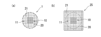
第一実施形態のハニカム構造体1は、ラジアントチューブヒータのチューブ内に配置される、単一の軸方向に延びて列設された隔壁20により区画された複数のセル21を備えるハニカム構造体1であって、軸方向に直交した断面において、中心部10のセル密度が、外周部11のセル密度よりも大きいものである。ここで、第一実施形態では、中心部10と外周部11とが一体成形されたものである。
The honeycomb structure 1 according to the first embodiment includes a plurality of
より詳細に説明すると、第一実施形態のハニカム構造体1はセラミックス製であり、セルが開口した端面側から見た平面図を図1(a)に示すように、断面の外形が正方形の中心部10の外周に沿って外周部11が形成された、断面の最外形が円形である円柱状である。また、中心部10のセル密度は外周部11のセル密度の2倍である。
More specifically, the honeycomb structure 1 of the first embodiment is made of ceramics, and a plan view viewed from the end face side where the cells are open is shown in FIG. The outer
このようなハニカム構造体1は、セラミックス粉末を水やバインダと混合した混練物を、押出成形した成形体を乾燥または焼成して形成されたものであり、押出成形の型としては、断面の外形が正方形の中心部分と、中心部分の外周に沿って形成された、セル密度が中心部分の1/2である外周部分とを有し、断面の最外形が正方形である型を使用することができる。これにより、図1(b)に示すように、断面の外形が正方形の中心部10と、中心部分の外周に沿って形成された、セル密度が中心部分の1/2である外周部11とを有し、断面の最外形が正方形である四角柱状の成形体25が得られる。この成形体25を乾燥させた乾燥体、または焼成した焼成体を、図中に一点鎖線で示すように切削加工し外形を円柱状に整えることにより、ハニカム構造体1が形成される。なお、図1(a)において、二点鎖線はハニカム構造体1の形状を明確にするために示したものであり、最外周のセル21は側面側で開口している。また、セル21の断面形状は正方形の場合を例示している。
Such a honeycomb structure 1 is formed by drying or firing a molded product obtained by extruding a kneaded material obtained by mixing ceramic powder with water or a binder. Using a mold having a square central portion and an outer peripheral portion formed along the outer periphery of the central portion and having a cell density that is ½ of the central portion, and having a square outermost section. it can. As a result, as shown in FIG. 1B, the
第一実施形態のハニカム構造体1によれば、中心部10のセル密度が外周部11のセル密度の2倍と大きいため、中心部10を流通する加熱流体に、流量を低減させるのに十分な抵抗がかかる。そして、中心部10に流入しにくく外周部11側に押し出された加熱流体が外周部11を流通することで、外周部11を流通する加熱流体の流量が増加する。従って、従来のハニカム構造体では中心部10に偏って流通していた加熱流体を、ハニカム構造体1の全体に均一に近付けて流通させることができる。これにより、ハニカム構造体1の大きな表面積が十分に活かされ、加熱流体の有する熱を効率的にチューブへ伝えることができる。また、最外周のセル21が側面側で開口していることにより、ハニカム構造体1の側面側で表面積が大きく、放射される熱量も大きいため、加熱流体の有する熱をより効率的にチューブへ伝えることができる。
According to the honeycomb structure 1 of the first embodiment, since the cell density of the
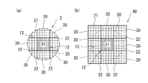
次に、第二実施形態のハニカム構造体について、図2を用いて説明する。ハニカム構造体2は、単一の方向に延びて列設された隔壁20により区画された複数のセル21を備えるハニカム構造を有するセグメント30,31が複数接合されて形成されているものであり、中心部12はセル密度が単一のセグメント31の一つによって形成されていると共に、外周部13はセル密度が単一のセグメント30の八つによって形成されている。
Next, the honeycomb structure of the second embodiment will be described with reference to FIG. The
より詳細に説明すると、第二実施形態のハニカム構造体2はセラミックス製であり、セル21が開口した端面側から見た平面図を図2(a)に示すように、断面の外形が正方形の中心部12の外周に沿って外周部13が形成された、断面の最外形が円形である円柱状である。また、中心部12のセル密度は外周部13のセル密度の2倍である。
More specifically, the
このような形状のハニカム構造体2は、図2(b)に示すように、セグメント30の2倍のセル密度を有する一つのセグメント31を中心として、その周囲に八つのセグメント30が配されており、隣接するセグメント30,31が耐熱性の接着材層22を介して接合された接合体40から形成される。なお、セグメント30,31は、それぞれセル密度が単一である型を用いて、四角柱状に押出成形されたものであり、セグメント31の型のセル密度は、セグメント30の型のセル密度の2倍である。そして、接合体40を図中に一点鎖線で示すように切削加工し、外形を円柱状に整えることにより、ハニカム構造体2が形成される。ここで、ハニカム構造体2において、セグメント31で構成される部分が中心部12に相当し、八つのセグメント30によって形成される部分が外周部13に相当する。なお、図2(a)において、二点鎖線はハニカム構造体2の形状を明確にするために示したものであり、最外周のセル21は側面側で開口している。
As shown in FIG. 2B, the
第二実施形態のハニカム構造体2によれば、従来のハニカム構造体(セグメント)を複数接合することにより、中心部12のセル密度が外周部13よりも大きいハニカム構造体を容易に製造することができる。これにより、新たな設備を導入する必要なく製造コストを抑えて、第一実施形態のハニカム構造体1と同様の作用効果を奏するハニカム構造体2を製造することができる。
According to the
上記のように、第一実施形態及び第二実施形態のハニカム構造体1,2によれば、中心部のセル密度を高めることにより、外周部を流通する加熱流体の流量を増やし、ハニカム構造体の全体にわたり均一に近付けて加熱流体を流通させることができる。これにより、ハニカム構造体の大きな表面積が有効に活用することができ、加熱流体の有する熱をチューブへ効率的に伝えることができる。加えて、最外周のセル21が側面側で開口していることにより、ハニカム構造体1,2の側面側で表面積が大きく、放射される熱量も大きいため、加熱流体の有する熱をより効率的にチューブへ伝えることができる。
As described above, according to the
また、第二実施形態のハニカム構造体2によれば、従来のハニカム構造体(セグメント)を複数接合することにより、セル密度に分布を有するハニカム構造体を容易に製造することができ、製造コストを抑えることができる。加えて、一般的に押出成形では、断面積の大きなハニカム構造体を製造しにくいところ、セグメントの接合により容易に断面積を大きくすることができるため、様々な大きさのラジアントチューブヒータに合わせた大きさのハニカム構造体を容易に製造することができる。
Moreover, according to the
以上、本発明について好適な実施形態を挙げて説明したが、本発明は上記の実施形態に限定されるものではなく、以下に示すように、本発明の要旨を逸脱しない範囲において、種々の改良及び設計の変更が可能である。 The present invention has been described with reference to the preferred embodiments. However, the present invention is not limited to the above-described embodiments, and various improvements can be made without departing from the scope of the present invention as described below. And design changes are possible.
例えば、第一実施形態のハニカム構造体1と同様に、中心部と外周部が一体となったハニカム構造体を押出成形により製造する場合、中心部の断面の外形は円形とすることができる。また、第二実施形態のハニカム構造体2と同様に、複数のセグメントの接合によりハニカム構造体を製造する場合、中心部を構成するセグメントの数は複数であっても良い。
For example, as with the honeycomb structure 1 of the first embodiment, when a honeycomb structure in which the central portion and the outer peripheral portion are integrated is manufactured by extrusion, the outer shape of the cross section of the central portion can be circular. Similarly to the
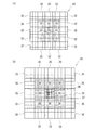
また、ハニカム構造体を、中心部と外周部の間に、セル密度が中心部よりも小さく、外周部よりも大きい中間部を備える構成とすることができる。このようなハニカム構造体は、図3(a)に例示するように、セル密度の異なる三種類のセグメント32,33,34の内、最もセル密度の大きいセグメント34を中心として、その周囲に二番目に大きいセル密度を有するセグメント33を接合し、更にその周囲に最もセル密度の小さいセグメント32を接合した接合体42から形成することができる。すなわち、このハニカム構造体は、セグメント34により構成された中心部、セグメント33により構成された中間部、セグメント32により構成された外周部を備えている。
Moreover, the honeycomb structure can be configured to include an intermediate portion between the center portion and the outer peripheral portion, in which the cell density is smaller than that of the central portion and larger than that of the outer peripheral portion. As illustrated in FIG. 3A, such a honeycomb structure has two
更に、ハニカム構造体が、中心部と外周部との間に、セル密度が中心部よりも小さく外周部よりも大きい中間部を備える場合に、中間部は更に、中心部側より外周部側でセル密度が小さい複数の部分で形成される構成とすることができる。このようなハニカム構造体は、図3(b)に示すように、セル密度の異なる四種類のセグメント35,36,37,38の内、最もセル密度の大きいセグメント38を中心として、その周囲に二番目に大きいセル密度を有するセグメント37を接合し、更にその周囲に三番目に大きいセル密度を有するセグメント36を接合し、最外周に最もセル密度の小さいセグメント35を接合した接合体43から形成することができる。すなわち、このハニカム構造体は、セグメント38により構成された中心部、セグメント37により構成された第一中間部、セグメント36により構成された第二中間部、セグメント35により構成された外周部を備えている。このように、中間部を備える構成では、ハニカム構造体の軸方向に直交する断面における加熱流体の流通し易さを、より精密に制御することができる。
Further, when the honeycomb structure includes an intermediate portion between the center portion and the outer peripheral portion, the cell density is smaller than the central portion and larger than the outer peripheral portion, the intermediate portion is further closer to the outer peripheral portion side than the central portion side. It can be set as the structure formed in several parts with small cell density. As shown in FIG. 3 (b), such a honeycomb structure has a
1,2 ハニカム構造体
20 隔壁
21 セル
30〜38 セグメント
1, 2
Claims (2)
前記軸方向に直交した断面において、中心部のセル密度が外周部のセル密度よりも大きい
ことを特徴とするハニカム構造体。 A honeycomb structure including a plurality of cells defined by partition walls arranged in a single axial direction and arranged in a tube of a radiant tube heater,
A honeycomb structure characterized in that, in a cross section orthogonal to the axial direction, a cell density in a central portion is larger than a cell density in an outer peripheral portion.
前記中心部及び前記外周部は、それぞれセル密度が単一の前記セグメントによって形成されている
ことを特徴とする請求項1に記載のハニカム構造体。 A plurality of segments having a honeycomb structure including a plurality of cells partitioned by partition walls extending in a single direction are joined and formed.
The honeycomb structure according to claim 1, wherein the central portion and the outer peripheral portion are each formed by the segments having a single cell density.
Priority Applications (1)
| Application Number | Priority Date | Filing Date | Title |
|---|---|---|---|
| JP2015002171A JP2016125797A (en) | 2015-01-08 | 2015-01-08 | Honeycomb structure |
Applications Claiming Priority (1)
| Application Number | Priority Date | Filing Date | Title |
|---|---|---|---|
| JP2015002171A JP2016125797A (en) | 2015-01-08 | 2015-01-08 | Honeycomb structure |
Publications (2)
| Publication Number | Publication Date |
|---|---|
| JP2016125797A true JP2016125797A (en) | 2016-07-11 |
| JP2016125797A5 JP2016125797A5 (en) | 2017-11-24 |
Family
ID=56357758
Family Applications (1)
| Application Number | Title | Priority Date | Filing Date |
|---|---|---|---|
| JP2015002171A Pending JP2016125797A (en) | 2015-01-08 | 2015-01-08 | Honeycomb structure |
Country Status (1)
| Country | Link |
|---|---|
| JP (1) | JP2016125797A (en) |
Citations (7)
| Publication number | Priority date | Publication date | Assignee | Title |
|---|---|---|---|---|
| US4702312A (en) * | 1986-06-19 | 1987-10-27 | Aluminum Company Of America | Thin rod packing for heat exchangers |
| JP2003254034A (en) * | 2002-02-26 | 2003-09-10 | Ngk Insulators Ltd | Honeycomb filter |
| JP4094823B2 (en) * | 2001-04-03 | 2008-06-04 | 日本碍子株式会社 | Honeycomb structure and assembly thereof |
| JP2011242086A (en) * | 2010-05-20 | 2011-12-01 | Covalent Materials Corp | High heat-conductive radiant tube |
| JP2013019644A (en) * | 2011-07-13 | 2013-01-31 | Nippon Steel & Sumitomo Metal Corp | Radiant tube and heating furnace |
| JP2013173134A (en) * | 2012-01-27 | 2013-09-05 | Denso Corp | Honeycomb structure |
| WO2014064812A1 (en) * | 2012-10-25 | 2014-05-01 | トヨタ自動車株式会社 | Heat exchanger |
-
2015
- 2015-01-08 JP JP2015002171A patent/JP2016125797A/en active Pending
Patent Citations (7)
| Publication number | Priority date | Publication date | Assignee | Title |
|---|---|---|---|---|
| US4702312A (en) * | 1986-06-19 | 1987-10-27 | Aluminum Company Of America | Thin rod packing for heat exchangers |
| JP4094823B2 (en) * | 2001-04-03 | 2008-06-04 | 日本碍子株式会社 | Honeycomb structure and assembly thereof |
| JP2003254034A (en) * | 2002-02-26 | 2003-09-10 | Ngk Insulators Ltd | Honeycomb filter |
| JP2011242086A (en) * | 2010-05-20 | 2011-12-01 | Covalent Materials Corp | High heat-conductive radiant tube |
| JP2013019644A (en) * | 2011-07-13 | 2013-01-31 | Nippon Steel & Sumitomo Metal Corp | Radiant tube and heating furnace |
| JP2013173134A (en) * | 2012-01-27 | 2013-09-05 | Denso Corp | Honeycomb structure |
| WO2014064812A1 (en) * | 2012-10-25 | 2014-05-01 | トヨタ自動車株式会社 | Heat exchanger |
Similar Documents
| Publication | Publication Date | Title |
|---|---|---|
| JP6587411B2 (en) | Radiant tube heating device | |
| JPWO2020094364A5 (en) | ||
| JP6577941B2 (en) | Heat exchanger, central heating equipment and hot water supply system provided with the same | |
| JP6652313B2 (en) | Arrangement structure of honeycomb structure | |
| JP2016125797A (en) | Honeycomb structure | |
| US10625251B2 (en) | Multistage body having a plurality of flow channels | |
| JP2015152190A (en) | gas turbine heat exchanger | |
| JP5788727B2 (en) | Radiant tube and heating furnace | |
| CN210689319U (en) | Heat storage brick and heat storage equipment | |
| RU2013125361A (en) | PROCESSED SURFACE FUEL PRE-MIXING PIPE | |
| CN202770183U (en) | Chain type annealing furnace | |
| JP2023028042A (en) | Honeycomb structure, its manufacturing method, and arrangement structure of honeycomb structure | |
| EP3794300A1 (en) | Heating radiator element | |
| JP2019174012A (en) | Heat exchanger | |
| CN219605396U (en) | Split-flow type intake chamber and radiator | |
| CN109839021A (en) | Three-dimensional matching combination gitter brick and heat storage | |
| JP6470571B2 (en) | Honeycomb structure and arrangement structure of honeycomb structure | |
| CN110567149B (en) | Heating device of water heater and water heater with same | |
| KR20170119265A (en) | Food dryer with ceramic heater | |
| US20130137056A1 (en) | Heat chamber | |
| JP2021124270A (en) | Heat exchanger | |
| BR102016012112B1 (en) | Device for indirect heating by radiation in the form of a radiant housing | |
| FI122176B (en) | Hearth | |
| JP5938710B2 (en) | Continuous heating device | |
| JP2021124268A (en) | Heat exchanger |
Legal Events
| Date | Code | Title | Description |
|---|---|---|---|
| A621 | Written request for application examination |
Free format text: JAPANESE INTERMEDIATE CODE: A621 Effective date: 20170829 |
|
| A521 | Request for written amendment filed |
Free format text: JAPANESE INTERMEDIATE CODE: A523 Effective date: 20171012 |
|
| A977 | Report on retrieval |
Free format text: JAPANESE INTERMEDIATE CODE: A971007 Effective date: 20180418 |
|
| A131 | Notification of reasons for refusal |
Free format text: JAPANESE INTERMEDIATE CODE: A131 Effective date: 20180515 |
|
| A02 | Decision of refusal |
Free format text: JAPANESE INTERMEDIATE CODE: A02 Effective date: 20181204 |