EP1484478A2 - Verfahren zur Steuerung der Bewegung eines Ankers eines elektromagnetischen Aktuators - Google Patents
Verfahren zur Steuerung der Bewegung eines Ankers eines elektromagnetischen Aktuators Download PDFInfo
- Publication number
- EP1484478A2 EP1484478A2 EP04012426A EP04012426A EP1484478A2 EP 1484478 A2 EP1484478 A2 EP 1484478A2 EP 04012426 A EP04012426 A EP 04012426A EP 04012426 A EP04012426 A EP 04012426A EP 1484478 A2 EP1484478 A2 EP 1484478A2
- Authority
- EP
- European Patent Office
- Prior art keywords
- valve
- armature
- actuator
- stroke
- current
- Prior art date
- Legal status (The legal status is an assumption and is not a legal conclusion. Google has not performed a legal analysis and makes no representation as to the accuracy of the status listed.)
- Withdrawn
Links
- 230000033001 locomotion Effects 0.000 title claims abstract description 20
- 238000000034 method Methods 0.000 title claims description 35
- 230000000694 effects Effects 0.000 claims abstract description 11
- 238000005259 measurement Methods 0.000 claims description 21
- 230000033228 biological regulation Effects 0.000 claims description 12
- 238000002485 combustion reaction Methods 0.000 claims description 9
- 230000004888 barrier function Effects 0.000 claims description 8
- 239000000725 suspension Substances 0.000 claims description 4
- 239000000654 additive Substances 0.000 claims 1
- 230000000996 additive effect Effects 0.000 claims 1
- 230000001133 acceleration Effects 0.000 abstract description 7
- 230000008859 change Effects 0.000 description 6
- 230000006870 function Effects 0.000 description 5
- 238000007667 floating Methods 0.000 description 4
- 230000000977 initiatory effect Effects 0.000 description 4
- 230000008569 process Effects 0.000 description 4
- 239000000853 adhesive Substances 0.000 description 3
- 230000001070 adhesive effect Effects 0.000 description 3
- 230000004907 flux Effects 0.000 description 3
- 230000007246 mechanism Effects 0.000 description 3
- 238000002360 preparation method Methods 0.000 description 3
- 230000002123 temporal effect Effects 0.000 description 3
- 238000012546 transfer Methods 0.000 description 3
- 230000032683 aging Effects 0.000 description 2
- 238000013459 approach Methods 0.000 description 2
- 230000006399 behavior Effects 0.000 description 2
- 230000008901 benefit Effects 0.000 description 2
- 238000012790 confirmation Methods 0.000 description 2
- 230000001276 controlling effect Effects 0.000 description 2
- 230000006378 damage Effects 0.000 description 2
- 230000007423 decrease Effects 0.000 description 2
- 238000001514 detection method Methods 0.000 description 2
- 238000011161 development Methods 0.000 description 2
- 230000018109 developmental process Effects 0.000 description 2
- 238000011156 evaluation Methods 0.000 description 2
- 238000004519 manufacturing process Methods 0.000 description 2
- 230000007935 neutral effect Effects 0.000 description 2
- 238000004026 adhesive bonding Methods 0.000 description 1
- 239000002313 adhesive film Substances 0.000 description 1
- 238000000418 atomic force spectrum Methods 0.000 description 1
- 230000005540 biological transmission Effects 0.000 description 1
- 238000010276 construction Methods 0.000 description 1
- 238000011109 contamination Methods 0.000 description 1
- 230000008878 coupling Effects 0.000 description 1
- 238000010168 coupling process Methods 0.000 description 1
- 238000005859 coupling reaction Methods 0.000 description 1
- 238000013016 damping Methods 0.000 description 1
- 238000013461 design Methods 0.000 description 1
- 238000010586 diagram Methods 0.000 description 1
- 238000010291 electrical method Methods 0.000 description 1
- 230000005611 electricity Effects 0.000 description 1
- 239000003344 environmental pollutant Substances 0.000 description 1
- 230000001771 impaired effect Effects 0.000 description 1
- 238000009434 installation Methods 0.000 description 1
- 235000013490 limbo Nutrition 0.000 description 1
- 230000003534 oscillatory effect Effects 0.000 description 1
- 231100000719 pollutant Toxicity 0.000 description 1
- 238000012545 processing Methods 0.000 description 1
- 230000001105 regulatory effect Effects 0.000 description 1
- 238000010079 rubber tapping Methods 0.000 description 1
- 238000000926 separation method Methods 0.000 description 1
- 230000003068 static effect Effects 0.000 description 1
Images

Classifications
-
- F—MECHANICAL ENGINEERING; LIGHTING; HEATING; WEAPONS; BLASTING
- F01—MACHINES OR ENGINES IN GENERAL; ENGINE PLANTS IN GENERAL; STEAM ENGINES
- F01L—CYCLICALLY OPERATING VALVES FOR MACHINES OR ENGINES
- F01L9/00—Valve-gear or valve arrangements actuated non-mechanically
- F01L9/20—Valve-gear or valve arrangements actuated non-mechanically by electric means
Definitions
- the present invention relates to a method for controlling the movement of a Armature of an electromagnetic actuator, in particular for actuating a Gas exchange valve of an internal combustion engine for a motor vehicle, the armature oscillating between pole faces of two electromagnetic coils against each other Force of a return spring is moved by energizing the solenoid coils becomes.
- a preferred application for an electromagnetic actuator with features the preamble of claim 1 is the electromagnetically actuated valve train of internal combustion engines.
- gas exchange valves are used actuated in the desired manner by such actuators, d. H. oscillatingly opened and closed.
- Actuator comprises as essential components an armature, which is between pole faces is arranged axially displaceable by two electromagnets and by at least a spring element in a central position between the two pole faces is held.
- the gas exchange valve designed as a lift valve is driven via a plunger that is rigidly connected to the armature of the actuator.
- valve disc In in a closed position of the valve, the valve disc is in a valve seat, and the armature of the actuator is against the restoring force of the spring element in contact with the pole face of the make coil.
- the armature of the actuator is detached from the closer coil and in the direction moved towards the opening coil.
- the plunger of the actuator acts on you Valve stem of the lift valve for power transmission.
- the anchor loosens with a great delay after overcoming an adhesive force of the armature on the pole face of the holding magnet and must now be up to Initiation of the actual valve opening also as the mechanical valve clearance overcome free flight distance.
- the size of the valve clearance is as above already indicated, dimensioned such that, for example, different thermal expansions with different operating conditions at no time can cause the plunger to stop when the armature is held in the closed position touches the valve stem or even presses the valve open and thus partially opens.
- the addition of component tolerances and different temperature expansions of the components involved as well as aging influences to the fact that the mechanical valve clearance is usually not exactly known. Thereby can disturbances in the function of the gasoline engine with regard to performance, Consumption and pollutant emissions occur.
- DE 198 32 198 describes a method in which the anchor uses a suitable control method from a rest position in contact with the pole face of a holding magnet out to an intermediate position.
- This intermediate position is through placing a part of the armature on the gas exchange valve designed as a lift valve characterized. This is the valve clearance when it reaches this Intermediate position of the valve clearance in the course of an electronically controlled valve clearance compensation already been bridged. From this intermediate position then the actual process of valve opening is operated. Accordingly a first end position when the gas exchange lift valve closes approached the armature, which is the placement of the gas exchange valve on his Valve seat corresponds.
- DE 195 31 437 A1 describes an electrical method for measuring the valve clearance disclosed on a gas exchange valve based on a relatively accurate determination the gluing time and a preliminary determination of a time period from detachment to Impact of the anchor is based. This method uses different measurement Difference time variables so that measurement inaccuracies add up very quickly can and ultimately lead to uncertain results.
- a method according to DE 198 34 545 A1 has proven to be considerably more reliable exposed.
- the measurement is carried out in a period in which When the gas exchange stroke valve is closed, a piston of the associated internal combustion engine cylinder is near its top dead center.
- the gas exchange valve By in this Phase inside the cylinder there is high pressure during the measurement and also by positioning the armature in contact with the gas exchange valve the gas exchange valve itself is never opened.
- the measurement itself takes place as an evaluation of the irregularity in a temporal course of movement of the anchor.
- no additional sensor is required.
- the measurement is done on the basis of the evaluation of a speed signal derived from the temporal Movement course of the armature is obtained: With a real valve play the armature is released from the holding position on the pole face of the closer magnet accelerated. As soon as the anchor hits the gas exchange valve, changes its temporal sequence of movements because of the resistance of the stationary gas exchange valve causes a significant decrease in anchor speed. This Change can take place even after a slight acceleration and a very short distance can be detected by the distance sensor, so that on this Basis the valve clearance can be determined.
- This measurement is made according to the Teaching of DE 198 34 545 A1 periodically or stochastically with interposition repeated several working cycles of the internal combustion engine.
- the armature may overshoot.
- the armature may overshoot however, cause the valve to open briefly even though the valve is closed must stay. In addition to significant losses in efficiency, this can also result in damage of the valve up to its destruction.
- a method according to the invention is accordingly characterized in that a measurable effect is exploited and in particular evaluated or monitored, to determine a partial detachment of the armature from a respective yoke.
- a measurable effect is exploited and in particular evaluated or monitored, to determine a partial detachment of the armature from a respective yoke.
- the armature of an actuator partially detaches a certain stream from the yoke. Is recognizable and verifiable this state at a stroke value at a speed that differs from zero from zero.
- Using such a confirmation measurement for each actuator or model according to a special current barrier Type of a parameter can be measured.
- the start of the regulation along the set curve begins after the partial detachment of the armature from the yoke has been recognized.
- a tolerance range for defines this current threshold can also be cyclical repeated control measurements are tracked, such as from the area of learning and / or self-tracking systems is known.
- the properties are improved of a method according to the invention a controller with setpoints for Current, stroke and speed used by an additional controlled variable is expanded.
- a controller with setpoints for Current, stroke and speed used by an additional controlled variable is expanded.
- the speed signal derived from the stroke signal can preferably be improved and in particular smoothed, that the controller is using a state estimator or observer is working. This also improves the quality of the new differential integral.
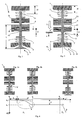
- FIG. 1 shows an actuator 1 of a known type which drives an associated globe valve 3 via a valve stem 2.
- Figure 1 shows with the open end position one of the two possible end positions of the globe valve 3 and of the actuator 1. In this position, a valve plate 5 is lifted off a valve seat 6, the lift valve 3 is thus open to the maximum. To transfer the globe valve 3 in a closed position, the valve plate 5 in the direction of its valve seat 6 moves.
- a valve closing spring 7 acts on this lifting valve 3.
- the valve closing spring However, 7 is dimensioned so that it the lifting valve 3 and with it can also only move the actuator 1 back into a neutral position.
- the actuator 1 comprises two electromagnetic coils 8, 9 a plunger 10 acting on the valve stem 2 of the globe valve 3, which the Armature 4 carries and between the electromagnet coils 8, 9 oscillating longitudinally is led.
- the plunger 10 of the actuator presses to drive the lift valve 3 1 over the valve stem 2 on the valve stem 2 of the globe valve 3.
- the arrangement shown is therefore an oscillatory one System for which the valve closing spring 7 and the valve opening spring 11 a first and form a second return spring. Depending on the spring force, a fine adjustment can be made over a length ⁇ I in the region of the valve opening spring 11.
- this is Lift valve 3 fully opened, and the armature 4 lies on the lower solenoid coil 8, which is also referred to below as NC coil 8, after this coil 8 holds the lift valve 3 in its open position.
- Length L between the armature 4 and the valve cover 5 is particularly critical. It is known that the length L during engine operation due to thermal Expansion or other type of wear changes, so that the length relations change within the arrangement of actuator 1 and lift valve 3. To ensure correct operation of the engine, this effect must be one relative change to the seat can be compensated in a suitable manner. In engines Hydraulic valve lash compensation is usually used with camshafts used. In addition to the complicated structure of this expensive and relatively prone to failure Solution is bought as another disadvantage that oil in the valve room can leak.
- Electronic valve clearance compensation has the advantage a much smaller number of components, the waiver of one Oil supply for hydraulic valve lash compensation and a significant simplification of system dynamics.
- Electronic valve clearance compensation is a typical one Example of a mechatronic implementation and is shown below Described with reference to the sequence of figures from Figure 3a to Figure 3c.
- the overall system consists of a mechanical as well as an electrical and a Software part together.
- the mechanical part of the valve clearance compensation is by an additional free distance V between the stem 2 of the valve 3 as well as the plunger 10 of the actuator 1, see Figures 2 and 3a. This distance must be chosen large enough so that the full range of a change in length ⁇ L of length L between the armature 4 and the valve cover 5 due to Component scatter, thermal expansion and wear can be safely compensated can.
- FIG. 4 To clarify the task of the software part of an electronic valve lash adjuster, an opening process of the lift valve 2 under the influence of the actuator 1 is illustrated with the aid of the sequence of figures FIGS. 3a to 3c and the addition of FIG. 4 to illustrate an opening movement.
- the armature 4 At the beginning, the armature 4 is in a closed position, in which the armature 4 is in flat contact with the pole face 13 of the opening magnet 8.
- the holding phase of the armature 4 in the closed position is ended by switching off the holding current I h . In fact, the armature 4 does not detach itself immediately from the pole face 13 of the closing magnet 9.
- the armature 4 is generally detached only at a later detaching time t L and thus with a time delay at the actual initiation time t E.
- This time delay is referred to in the literature as the so-called "sticking time" t k . It is always different in size even within a series of actuators 1 and can also change over time during operation in an actuator 1.
- the cause of this adhesive time t k is the remanent magnetic field strength of the opening magnets 8, which decreases only in a finite time after the holding current l h has been switched off, supported by the static friction between the armature 4 and the pole face 13 and possibly extended by an adhesive film made of oil and fat etc. on the pole face 13. Due to the occurrence of the adhesive time t k , the initiation time t E cannot be used as the starting point for controlling the valve opening time ⁇ T.
- the actuator 1 Under the effect of the restoring force of the valve opener spring 11, the actuator 1 is moved until the valve 3 has lifted out of the valve seat 6 by lifting the valve head 5.
- This movement is carried out in two sections, the plunger 10 being transferred by the armature 4 into an intermediate position with a stroke z s at the time t s after the delay t k has been overcome.
- This stroke z s is a little smaller than the valve clearance V, so that the tappet 10 of the actuator 1 is not in contact with the stem 2 of the valve 3.
- This section of the movement has been identified in FIG. 2 by an arrow P 1 , which is also shown in FIG. 4. This prevents the valve 3 from opening prematurely.
- the actual and now very timely opening of the valve 3 takes place in the course of a movement section P2 in which the plunger 10 presses on the shaft 2 against the restoring force of the restoring and shooting spring 7.
- valve 3 When valve 3 is closed, the sequence of movements described is reversed, that is, valve 3, curve a in FIG. 4 closes, and armature 4 then moves into its rest position.
- the armature 4 is held in a short distance above the pole face 13 of the closing magnet 9 in a position Z s .
- the armature 4 is gently moved in the course of a control process with suitable energization of at least one of the magnets 8, 9 against the restoring force of the valve opening spring 11 into an intermediate stroke position z s .
- This intermediate position z s has been selected so that it is slightly smaller than a respective valve clearance V of the actuator-valve unit.
- the armature 4 is in a state of suspension from a point in time t s , the plunger 10 almost abutting the valve stem 2. It is thus ensured in this intermediate position that the valve 3 itself is never opened at this time t s , not even due to control deviations or vibrations impressed from the outside.
- the floating state is outlined in the illustration in FIG. 3b and indicates a ready position from which the valve 3 can be opened at any time t 1 . This ensures that an opening movement of the valve 3 now takes place in a defined manner and almost immediately with the application of a suitable current supply.
- the novel intermediate state can thus be freely used to set a specific start time t 1 at the beginning of an adjustable valve opening period ⁇ T.
- the implementation of the described method in a corresponding device eliminates numerous problems, such as noise and wear due to the continuous tapping of the tappet 10 on the valve stem 2.
- the valve clearance V itself advantageously does not have to be exactly known in terms of its size, since only one position Z s is approached. Constant measurements of the valve clearance can thus be satisfied; checks at wide intervals are sufficient in accordance with the methods described at the beginning with reference to the relevant prior art.
- FIG. 5 shows the course of an overall spring force F f acting on the armature 4 over the stroke z, here shown symmetrically to a neutral central position of the armature between the pole faces 12, 13 of the electromagnets 8, 9.
- the spring force curve F f (z) is shown as an essentially linear relationship over the armature stroke z. However, in the direction of the opening magnet 8, the curve of the total spring force F f has a significant jump in force at the marked point. This jump in force occurs at the time at the position of the armature stroke z at which the tappet 10 rigidly connected to the armature 4 occurs on the valve stem 2 and must furthermore act against the resilient restoring forces of the closer side.
- this force jump can be used by additional sensors to determine the valve clearance, or to measure the valve clearance by electrical means by measuring current and voltage according to the teaching of DE 195 31 437 A1.
- processing is preferably carried out without additional sensors, in particular according to the teaching of DE 198 34 545 A1.
- a stroke z s is approached in a targeted manner just before overcoming a respective valve clearance V, the electromagnets 8, 9 involved being each designed to build up or break down a magnetic flux in order to overcome this jump in force.
- the method described above builds on the armature 4 first is completely detached from the pole face 13 of the holding magnet 9 and then immediately held in suspension at a short distance above the pole face 13 becomes.
- the plunger 10 rigidly connected to the armature 4 is not in System on the valve stem 2.
- the magnetic flux in the holding magnet 9 is first reduced so far, that the spring force is greater than the magnetic force. Only then can the anchor 4 set in motion at all or from the pole face 13 of the holding magnet 9 to solve.
- a required flux in the holding magnet 9 can be built up to hold the anchor 4 in suspension in a defined manner.
- a controller with setpoints for current, stroke and speed is used, which is expanded by an additional control variable.
- a constant stroke z s as the floating height of the armature 4 above the pole face 13 of the closing magnet 9, a speed v ⁇ 0 and, in addition, a consistent value for the current flow I through the holding coil 9 are specified as target values. Characterized in that the difference between the desired and actual values of Z is intended, z is integrated for the stroke, even very small permanent deviations are detected and corrected. Sticking of the armature 4 on the pole face 13 is reliably prevented since the increasing differential integral results in a growing current flow. Forces are built up in a very short time, which can overcome any known sticking of the armature 4 on the pole face 13.
- a current flow which is too high immediately after the armature 4 is detached from the pole face 13 is returned from the differential integral in such a way by the new controlled variable that pendulum movements are suppressed or very quickly corrected.
- the controller is always active, i.e. of Beginning with the anchor on and ending with the floating anchor 4. Guaranteed the controller always operates the actuator 1 safely.
- FIG. 6 shows the measurement result in a simplified form: A curve of the stroke z (t) is shown for a case u with and a case g without partial lifting. The curve u runs very quickly with a high gradient from the vicinity of the origin.
- the curve profile g is characterized by a very weakly pronounced, approximately ramp-shaped increase, which is essentially only converted into the profile of the curve u from a predetermined point in time t 1 .
- This distinguishing section indicates a partial detachment of the armature from the yoke.
- This particularly desired state can be recognized and checked on the basis of a stroke value z different from the value zero at a speed v of approximately zero.
- a special current barrier l s can be measured for each actuator 1 or a respective model in the manner of a parameter.
- the size ⁇ l has a value of approximately 0.5A.
- a current measurement in the form of a simple threshold value detection serves to detect the partial detachment by evaluating a current barrier l s .
- the start of the regulation along a set curve begins after the partial detachment of the armature 4 from the yoke 12, 13 has been recognized.
- the speed of the armature 4 which is significantly lower than that of the prior art after detaching, from the start of the transfer into the intermediate position, means that the armature can now be approached even more precisely without overshoots.
- the force used to detach the armature according to known methods and an excessive acceleration of the armature that occurs immediately after detachment are eliminated, since partial detachment of the armature from the yoke of the associated electromagnet has already been effected beforehand. This saves electricity.
- a tolerance range for this current threshold is additionally defined in a further embodiment of the invention.
- the result is a control curve with hysteresis, the width of which is included in the control as a current tolerance.
- This tolerance range can also be kept very low and the control accuracy can be increased by carrying out cyclically repeated control measurements.
- the size of the current barrier I s can also be tracked, as is known in principle, for example, from the area of learning and / or self-tracking systems.
- Such a unit advantageously comprises a comparatively small number for an electromagnetic valve train of components and individual parts and in particular dispenses with an oil supply a hydraulic valve lash adjuster. Moving additional Requirements in the field of regulation as well as the preparation of electrical Measurement signals without the use of additional sensors, etc. is a simplification overall system dynamics.
Landscapes
- Engineering & Computer Science (AREA)
- Mechanical Engineering (AREA)
- General Engineering & Computer Science (AREA)
- Magnetically Actuated Valves (AREA)
- Valve Device For Special Equipments (AREA)
Abstract
Description
- Figur 1:
- einen prinzipiellen Aufbau eines Gaswechselventils mit elektromagnetischem Aktuator-Antrieb in einer geöffneten Endstellung;
- Figur 2:
- die Anordnung gemäß Figur 1 in einer geschlossenen Endstellung;
- Figuren 3a bis 3c:
- ein Gaswechselventil bekannter Bauart mit Ventilspiel in drei unterschiedlichen Betriebszuständen;
- Figur 4:
- ein zeitlicher Verlauf des Hubes des Ankers und des Ventildeckels;
- Figur 5:
- ein Diagramm zur Darstellung des Zusammenhangs zwischen der Gesamtfederkraft aufgetragen über dem Ankerhub;
- Figur 6:
- eine Gegenüberstellung von zwei Ablöseverhalten und
- Figur 7:
- eine Gegenüberstellung von zwei Folgeverhalten beim Anfahren einer Zwischenposition als Vergrößerung eines Ausschnitts von Figur 4.
- 1
- Aktuator
- 2
- Ventilschaft
- 3
- Hubventil
- 4
- Anker
- 5
- Ventilteller
- 6
- Ventilsitz
- 7
- Ventilschließfeder
- 8
- Elektromagnet-Spule
- 9
- Elektromagnet-Spule
- 10
- Stößel
- 11
- Ventil-Öffnungsfeder
- 12
- Polfläche
- 13
- Polfläche
- ls
- Stromschranke
- lmin
- minimaler Strom durch eine Elektromagnet-Spule 8,9
- Δl
- Längenänderung zur Federeinstellung
- L
- Länge zwischen Anker 4 und dem Ventil 5
- t
- Zeit
- tk
- Klebzeit
- tL
- Lösezeitpunkt
- t1
- Startzeitpunkt einer Ventilöffung
- ts
- Zeitpunkt, zu dem Zwischenposition zserreicht wird
- Δt
- Zeitdifferenz zwischen Lösezeitpunkt und Startzeit der Ventilöffnung
- ΔT
- einstellbare Ventilöffnungszeitspanne
- V
- Ventilspiel
- z
- Wegkoordinate des Ankers 4 / Hub
- z0
- Startwert / Hub in Schließstellung
- ze
- Endwert / maximale Öffnungsstellung
- zs
- Zwischenposition
Claims (10)
- Verfahren zur Steuerung der Bewegung eines Ankers (4) eines elektromagnetischen Aktuators (1), insbesondere zur Betätigung eines Gaswechsel- Hubventiles (3) einer Brennkraftmaschine für ein Kraftfahrzeug, wobei der Anker (4) oszillierend zwischen Polflächen (12, 13) zweier Elektromagnet-Spulen (8, 9) jeweils gegen die Kraft zumindest einer Rückstellfeder (7, 11) durch Bestromung mindestens einer Elektromagnet-Spule (8, 9) bewegt wird,
dadurch gekennzeichnet, dass
als Ausgangspunkt für eine Regelung ein messbarer Effekt ausgenutzt wird, wonach sich der Anker (4) des Aktuators (1) insbesondere bei einem bestimmten Strom (ls) teilweise vom Joch (12, 13) löst. - Verfahren nach Anspruch 1,
dadurch gekennzeichnet, dass der Beginn der Regelung entlang der Sollkurve nach dem Erkennen des partiellen Ablösens des Ankers (4) von dem Joch (12, 13) einsetzt. - Verfahren nach einem oder mehreren der vorhergehenden Ansprüche,
dadurch gekennzeichnet, dass eine Strommessung der Erkennung des partiellen Ablösens durch Auswertung einer Stromschranke (ls) von ls =lmin+Δl dient, wobei der additive Term (Δl) ungefähr einen Wert von 0,5A hat. - Verfahren nach einem oder mehreren der vorhergehenden Ansprüche,
dadurch gekennzeichnet, dass der Anker (4) des Aktuators (1) in einer Vorbereitungsphase von der Polfläche (13) des Schließermagneten (9) abgehoben wird und der Stößel (10) des Aktuators (1) mit sehr geringer Geschwindigkeit auf den Ventilschaft (2) knapp unterhalb einer Position des Schaftes (2) gefahren und dort in der Schwebe gehalten wird. - Verfahren nach einem oder mehreren der vorhergehenden Ansprüche,
dadurch gekennzeichnet, dass durch eine Ansteuerung des Aktuators (1) aus dieser Bereitschaftslage (zs) in Kontakt des Ventilschaftes (2) mit dem Stößel (10) des Aktuators (1 ) heraus ein Startzeitpunkt (t1) einer Ventilöffnung festgelegt wird. - Verfahren nach einem oder mehreren der vorhergehenden Ansprüche,
dadurch gekennzeichnet, dass in weiten zeitlichen Intervallen ein jeweiliges Ventilspiel (V) bestimmt wird. - Verfahren nach einem oder mehreren der vorhergehenden Ansprüche,
dadurch gekennzeichnet, dass ein Regler mit Sollwerten für Strom (I), Hub (z) und Geschwindigkeit (v) verwendet wird, der durch eine zusätzliche Regelgröße (y) erweitert wird, die aus bereits vorhandenen Regelgrößen abgeleitet wird. - Verfahren nach dem vorhergehenden Anspruch, dadurch gekennzeichnet, dass die zusätzliche Regelgröße (y) als zeitliches Integral der Differenz zwischen einem Soll-Hub (zsoll) und einem Ist-Hub (zist) bestimmt wird.
- Verfahren nach einem der vorhergehenden Ansprüche, dadurch gekennzeichnet, dass der Regler unter Verwendung eines Zustandsschätzers arbeitet.
- Vorrichtung zur Steuerung der Bewegung eines Ankers (4) in einem elektromagnetischen Aktuator (1), der einen axial zwischen Polflächen (12, 13) von zwei Elektromagneten (8, 9) aufweist, zwischen denen der Anker verschieblich ist, wobei der Aktuator (1) insbesondere zum Antrieb eines Hubventils (3) ausgebildet ist,
dadurch gekennzeichnet, dass die Vorrichtung zur Durchführung eines Verfahrens nach einem oder mehreren der vorhergehenden Ansprüche ausgebildet ist.
Applications Claiming Priority (2)
| Application Number | Priority Date | Filing Date | Title |
|---|---|---|---|
| DE10325705A DE10325705B3 (de) | 2003-06-06 | 2003-06-06 | Verfahren zur Steuerung der Bewegung eines Ankers eines elektromagnetischen Aktuators |
| DE10325705 | 2003-06-06 |
Publications (2)
| Publication Number | Publication Date |
|---|---|
| EP1484478A2 true EP1484478A2 (de) | 2004-12-08 |
| EP1484478A3 EP1484478A3 (de) | 2008-08-06 |
Family
ID=33154579
Family Applications (1)
| Application Number | Title | Priority Date | Filing Date |
|---|---|---|---|
| EP04012426A Withdrawn EP1484478A3 (de) | 2003-06-06 | 2004-05-25 | Verfahren zur Steuerung der Bewegung eines Ankers eines elektromagnetischen Aktuators |
Country Status (2)
| Country | Link |
|---|---|
| EP (1) | EP1484478A3 (de) |
| DE (1) | DE10325705B3 (de) |
Citations (6)
| Publication number | Priority date | Publication date | Assignee | Title |
|---|---|---|---|---|
| DE2335150A1 (de) | 1972-07-12 | 1974-01-24 | British Leyland Austin Morris | Verbrennungsmotor |
| DE19529155A1 (de) | 1995-08-08 | 1997-02-13 | Fev Motorentech Gmbh & Co Kg | Verfahren zur Messung des Ventilspiels an einem durch einen elektromagnetischen Aktuator betätigten Gaswechselventil |
| DE19531437A1 (de) | 1995-08-26 | 1997-02-27 | Fev Motorentech Gmbh & Co Kg | Verfahren zur Erfassung des Ventilspiels an einem durch einen elektromagnetischen Aktuator betätigten Gaswechselventil |
| DE19832198A1 (de) | 1998-07-17 | 2000-01-20 | Bayerische Motoren Werke Ag | Regelungsverfahren für die Endphasen-Bewegung eines Ankers eines elektromagnetischen Aktuators |
| DE19834545A1 (de) | 1998-07-31 | 2000-02-03 | Bayerische Motoren Werke Ag | Verfahren zur Messung des Spiels zwischen einem Gaswechselventil einer Hubkolben-Brennkraftmaschine und einem dieses betätigenden elektromagnetischen Aktuator |
| DE19947848A1 (de) | 1998-10-28 | 2000-05-04 | Fev Motorentech Gmbh | Aktuator zur Betätigung eines Stellgliedes, insbesondere eines Gaswechselventils mit einseitiger Federanordnung |
Family Cites Families (7)
| Publication number | Priority date | Publication date | Assignee | Title |
|---|---|---|---|---|
| DE4434684A1 (de) * | 1994-09-28 | 1996-04-04 | Fev Motorentech Gmbh & Co Kg | Verfahren zur Steuerung der Ankerbewegung einer elektromagnetischen Schaltanordnung |
| US6942469B2 (en) * | 1997-06-26 | 2005-09-13 | Crystal Investments, Inc. | Solenoid cassette pump with servo controlled volume detection |
| EP0973177B1 (de) * | 1998-07-17 | 2004-09-29 | Bayerische Motoren Werke Aktiengesellschaft, Patentabteilung AJ-3 | Verfahren zur Bewegungssteuerung eines Ankers eines elektromagnetischen Aktuators |
| DE10019745A1 (de) * | 1999-05-27 | 2000-11-30 | Fev Motorentech Gmbh | Verfahren zur Ansteuerung eines elektromagnetischen Aktuators zur Betätigung eines Gaswechselventils an einer Kolbenbrennkraftmaschine |
| DE10062107C5 (de) * | 2000-12-13 | 2004-05-13 | Daimlerchrysler Ag | Aktorregelung |
| DE10205384A1 (de) * | 2002-02-09 | 2003-08-21 | Bayerische Motoren Werke Ag | Verfahren zur Steuerung der Bewegung eines Ankers eines elektromagnetischen Aktuators |
| DE10206031B4 (de) * | 2002-02-14 | 2007-08-30 | Bayerische Motoren Werke Ag | Verfahren zur Steuerung der Bewegung eines Ankers eines elektromagnetischen Aktuators |
-
2003
- 2003-06-06 DE DE10325705A patent/DE10325705B3/de not_active Expired - Lifetime
-
2004
- 2004-05-25 EP EP04012426A patent/EP1484478A3/de not_active Withdrawn
Patent Citations (6)
| Publication number | Priority date | Publication date | Assignee | Title |
|---|---|---|---|---|
| DE2335150A1 (de) | 1972-07-12 | 1974-01-24 | British Leyland Austin Morris | Verbrennungsmotor |
| DE19529155A1 (de) | 1995-08-08 | 1997-02-13 | Fev Motorentech Gmbh & Co Kg | Verfahren zur Messung des Ventilspiels an einem durch einen elektromagnetischen Aktuator betätigten Gaswechselventil |
| DE19531437A1 (de) | 1995-08-26 | 1997-02-27 | Fev Motorentech Gmbh & Co Kg | Verfahren zur Erfassung des Ventilspiels an einem durch einen elektromagnetischen Aktuator betätigten Gaswechselventil |
| DE19832198A1 (de) | 1998-07-17 | 2000-01-20 | Bayerische Motoren Werke Ag | Regelungsverfahren für die Endphasen-Bewegung eines Ankers eines elektromagnetischen Aktuators |
| DE19834545A1 (de) | 1998-07-31 | 2000-02-03 | Bayerische Motoren Werke Ag | Verfahren zur Messung des Spiels zwischen einem Gaswechselventil einer Hubkolben-Brennkraftmaschine und einem dieses betätigenden elektromagnetischen Aktuator |
| DE19947848A1 (de) | 1998-10-28 | 2000-05-04 | Fev Motorentech Gmbh | Aktuator zur Betätigung eines Stellgliedes, insbesondere eines Gaswechselventils mit einseitiger Federanordnung |
Also Published As
| Publication number | Publication date |
|---|---|
| EP1484478A3 (de) | 2008-08-06 |
| DE10325705B3 (de) | 2005-05-25 |
Similar Documents
| Publication | Publication Date | Title |
|---|---|---|
| EP0973178B1 (de) | Verfahren zur Bewegungssteuerung eines Ankers eines elektromagnetischen Aktuators | |
| DE19640659B4 (de) | Verfahren zur Betätigung eines elektromagnetischen Aktuators mit Beeinflussung des Spulenstroms während der Ankerbewegung | |
| DE19526681B4 (de) | Verfahren zur zeitgenauen Steuerung der Ankerbewegung eines elektromagnetisch betätigbaren Stellmittels | |
| DE19843073C1 (de) | Verfahren zum Betreiben eines elektromagnetischen Aktuators zur Betätigung eines Gaswechselventils | |
| DE102011016895B4 (de) | Verfahren zur Bestimmung des Verschleißzustandes eines elektromagnetischen Aktors während dessen Betriebs | |
| EP0973177B1 (de) | Verfahren zur Bewegungssteuerung eines Ankers eines elektromagnetischen Aktuators | |
| DE10012988A1 (de) | Verfahren zum Betrieb eines elektromagnetischen Aktors | |
| DE19832196A1 (de) | Verfahren zur Reduzierung der Auftreffgeschwindigkeit eines Ankers eines elektromagnetischen Aktuators | |
| DE10019745A1 (de) | Verfahren zur Ansteuerung eines elektromagnetischen Aktuators zur Betätigung eines Gaswechselventils an einer Kolbenbrennkraftmaschine | |
| DE10206031B4 (de) | Verfahren zur Steuerung der Bewegung eines Ankers eines elektromagnetischen Aktuators | |
| EP1101015B1 (de) | Verfahren zur ansteuerung eines elektromagnetischen aktuators zur betätigung eines gaswechselventils an einer kolbenbrennkraftmaschine | |
| DE10325705B3 (de) | Verfahren zur Steuerung der Bewegung eines Ankers eines elektromagnetischen Aktuators | |
| DE19860197A1 (de) | Verfahren zur Erkennung von Zündaussetzern an einer Kolbenbrennkraftmaschine | |
| DE102004054776B3 (de) | Verfahren zur Kalibrierung eines Wegsensors einer Drehaktuatorvorrichtung zur Ansteuerung eines Gaswechselventils einer Brennkraftmaschine | |
| DE10062107C5 (de) | Aktorregelung | |
| DE10318244A1 (de) | Verfahren zur Steuerung der Bewegung eines Ankers eines elektromagnetischen Aktuators | |
| DE10244337B4 (de) | Verfahren zur Steuerung der Bewegung eines Ankers eines elektromagnetischen Aktuators | |
| DE10325706B4 (de) | Verfahren zur Steuerung der Bewegung eines Ankers eines elektromagnetischen Aktuators | |
| DE10257693B4 (de) | Verfahren zur Steuerung der Bewegung eines Ankers eines elektromagnetischen Aktuators | |
| DE10205383B4 (de) | Verfahren zur Steuerung der Bewegung eines Ankers eines elektromagnetischen Aktuators | |
| DE10318245B4 (de) | Verfahren zur Steuerung der Bewegung eines Ankers eines elektromagnetischen Aktuators | |
| DE10205384A1 (de) | Verfahren zur Steuerung der Bewegung eines Ankers eines elektromagnetischen Aktuators | |
| DE10205387A1 (de) | Verfahren zur Steuerung der Bewegung eines Ankers eines elektromagnetischen Aktuators | |
| DE10136497A1 (de) | Verfahren zur Bestimmung des Spiels zwischen dem Schaft eines Ventils und einem Aktuator und Aktuator zur Durchführung des Verfahrens | |
| DE19922969A1 (de) | Verfahren zum Betrieb eines elektromagnetischen Ventiltriebs zur Betätigung eines Gaswechselventils an einer Kolbenbrennkraftmaschine |
Legal Events
| Date | Code | Title | Description |
|---|---|---|---|
| PUAI | Public reference made under article 153(3) epc to a published international application that has entered the european phase |
Free format text: ORIGINAL CODE: 0009012 |
|
| AK | Designated contracting states |
Kind code of ref document: A2 Designated state(s): AT BE BG CH CY CZ DE DK EE ES FI FR GB GR HU IE IT LI LU MC NL PL PT RO SE SI SK TR |
|
| AX | Request for extension of the european patent |
Extension state: AL HR LT LV MK |
|
| PUAL | Search report despatched |
Free format text: ORIGINAL CODE: 0009013 |
|
| AK | Designated contracting states |
Kind code of ref document: A3 Designated state(s): AT BE BG CH CY CZ DE DK EE ES FI FR GB GR HU IE IT LI LU MC NL PL PT RO SE SI SK TR |
|
| AX | Request for extension of the european patent |
Extension state: AL HR LT LV MK |
|
| STAA | Information on the status of an ep patent application or granted ep patent |
Free format text: STATUS: THE APPLICATION HAS BEEN WITHDRAWN |
|
| 18W | Application withdrawn |
Effective date: 20081024 |