EP1484133B1 - Werkzeug- oder Produktionsmaschine mit durchsichtiger Scheibe und Head-up-Display - Google Patents
Werkzeug- oder Produktionsmaschine mit durchsichtiger Scheibe und Head-up-Display Download PDFInfo
- Publication number
- EP1484133B1 EP1484133B1 EP04011545A EP04011545A EP1484133B1 EP 1484133 B1 EP1484133 B1 EP 1484133B1 EP 04011545 A EP04011545 A EP 04011545A EP 04011545 A EP04011545 A EP 04011545A EP 1484133 B1 EP1484133 B1 EP 1484133B1
- Authority
- EP
- European Patent Office
- Prior art keywords
- machine
- production
- display
- head
- tool
- Prior art date
- Legal status (The legal status is an assumption and is not a legal conclusion. Google has not performed a legal analysis and makes no representation as to the accuracy of the status listed.)
- Expired - Lifetime
Links
- 238000004519 manufacturing process Methods 0.000 title claims description 37
- 238000000034 method Methods 0.000 claims description 8
- 238000012800 visualization Methods 0.000 claims description 7
- 238000005516 engineering process Methods 0.000 description 9
- 230000007613 environmental effect Effects 0.000 description 3
- 239000011521 glass Substances 0.000 description 3
- 238000003801 milling Methods 0.000 description 3
- 238000005520 cutting process Methods 0.000 description 2
- 238000004088 simulation Methods 0.000 description 2
- 238000013459 approach Methods 0.000 description 1
- 239000000919 ceramic Substances 0.000 description 1
- 238000011109 contamination Methods 0.000 description 1
- 238000005553 drilling Methods 0.000 description 1
- 238000000227 grinding Methods 0.000 description 1
- 238000007689 inspection Methods 0.000 description 1
- 238000003754 machining Methods 0.000 description 1
- 239000000463 material Substances 0.000 description 1
- 238000012544 monitoring process Methods 0.000 description 1
- 238000012536 packaging technology Methods 0.000 description 1
- 239000004033 plastic Substances 0.000 description 1
- 229920003023 plastic Polymers 0.000 description 1
- 238000007639 printing Methods 0.000 description 1
- 238000012545 processing Methods 0.000 description 1
- 238000000926 separation method Methods 0.000 description 1
- 239000004575 stone Substances 0.000 description 1
- 239000004753 textile Substances 0.000 description 1
- 230000036964 tight binding Effects 0.000 description 1
- 238000012546 transfer Methods 0.000 description 1
- 238000007514 turning Methods 0.000 description 1
- 230000000007 visual effect Effects 0.000 description 1
Images

Classifications
-
- B—PERFORMING OPERATIONS; TRANSPORTING
- B23—MACHINE TOOLS; METAL-WORKING NOT OTHERWISE PROVIDED FOR
- B23Q—DETAILS, COMPONENTS, OR ACCESSORIES FOR MACHINE TOOLS, e.g. ARRANGEMENTS FOR COPYING OR CONTROLLING; MACHINE TOOLS IN GENERAL CHARACTERISED BY THE CONSTRUCTION OF PARTICULAR DETAILS OR COMPONENTS; COMBINATIONS OR ASSOCIATIONS OF METAL-WORKING MACHINES, NOT DIRECTED TO A PARTICULAR RESULT
- B23Q11/00—Accessories fitted to machine tools for keeping tools or parts of the machine in good working condition or for cooling work; Safety devices specially combined with or arranged in, or specially adapted for use in connection with, machine tools
- B23Q11/08—Protective coverings for parts of machine tools; Splash guards
- B23Q11/0891—Protective coverings for parts of machine tools; Splash guards arranged between the working area and the operator
-
- B—PERFORMING OPERATIONS; TRANSPORTING
- B23—MACHINE TOOLS; METAL-WORKING NOT OTHERWISE PROVIDED FOR
- B23Q—DETAILS, COMPONENTS, OR ACCESSORIES FOR MACHINE TOOLS, e.g. ARRANGEMENTS FOR COPYING OR CONTROLLING; MACHINE TOOLS IN GENERAL CHARACTERISED BY THE CONSTRUCTION OF PARTICULAR DETAILS OR COMPONENTS; COMBINATIONS OR ASSOCIATIONS OF METAL-WORKING MACHINES, NOT DIRECTED TO A PARTICULAR RESULT
- B23Q11/00—Accessories fitted to machine tools for keeping tools or parts of the machine in good working condition or for cooling work; Safety devices specially combined with or arranged in, or specially adapted for use in connection with, machine tools
- B23Q11/08—Protective coverings for parts of machine tools; Splash guards
-
- B—PERFORMING OPERATIONS; TRANSPORTING
- B23—MACHINE TOOLS; METAL-WORKING NOT OTHERWISE PROVIDED FOR
- B23Q—DETAILS, COMPONENTS, OR ACCESSORIES FOR MACHINE TOOLS, e.g. ARRANGEMENTS FOR COPYING OR CONTROLLING; MACHINE TOOLS IN GENERAL CHARACTERISED BY THE CONSTRUCTION OF PARTICULAR DETAILS OR COMPONENTS; COMBINATIONS OR ASSOCIATIONS OF METAL-WORKING MACHINES, NOT DIRECTED TO A PARTICULAR RESULT
- B23Q17/00—Arrangements for observing, indicating or measuring on machine tools
- B23Q17/24—Arrangements for observing, indicating or measuring on machine tools using optics or electromagnetic waves
-
- G—PHYSICS
- G05—CONTROLLING; REGULATING
- G05B—CONTROL OR REGULATING SYSTEMS IN GENERAL; FUNCTIONAL ELEMENTS OF SUCH SYSTEMS; MONITORING OR TESTING ARRANGEMENTS FOR SUCH SYSTEMS OR ELEMENTS
- G05B2219/00—Program-control systems
- G05B2219/30—Nc systems
- G05B2219/32—Operator till task planning
- G05B2219/32014—Augmented reality assists operator in maintenance, repair, programming, assembly, use of head mounted display with 2-D 3-D display and voice feedback, voice and gesture command
-
- Y—GENERAL TAGGING OF NEW TECHNOLOGICAL DEVELOPMENTS; GENERAL TAGGING OF CROSS-SECTIONAL TECHNOLOGIES SPANNING OVER SEVERAL SECTIONS OF THE IPC; TECHNICAL SUBJECTS COVERED BY FORMER USPC CROSS-REFERENCE ART COLLECTIONS [XRACs] AND DIGESTS
- Y10—TECHNICAL SUBJECTS COVERED BY FORMER USPC
- Y10T—TECHNICAL SUBJECTS COVERED BY FORMER US CLASSIFICATION
- Y10T409/00—Gear cutting, milling, or planing
- Y10T409/30—Milling
- Y10T409/30392—Milling with means to protect operative or machine [e.g., guard, safety device, etc.]
-
- Y—GENERAL TAGGING OF NEW TECHNOLOGICAL DEVELOPMENTS; GENERAL TAGGING OF CROSS-SECTIONAL TECHNOLOGIES SPANNING OVER SEVERAL SECTIONS OF THE IPC; TECHNICAL SUBJECTS COVERED BY FORMER USPC CROSS-REFERENCE ART COLLECTIONS [XRACs] AND DIGESTS
- Y10—TECHNICAL SUBJECTS COVERED BY FORMER USPC
- Y10T—TECHNICAL SUBJECTS COVERED BY FORMER US CLASSIFICATION
- Y10T409/00—Gear cutting, milling, or planing
- Y10T409/30—Milling
- Y10T409/309576—Machine frame
Definitions
- the invention relates to a tool or production machine, wherein the machine has a visible by means of at least one transparent pane by the operator workspace.
- a display unit or a control panel with the aid of which the production or production process can be parameterized and monitored on site.
- a display unit while a tube or LCD screen is usually used. This is usually located next to or in front of the machine as an integral part of a control panel or is mounted on a movable so-called gallows.
- the invention is based on the idea that a head-up display is used as the display unit.
- the head-up display can be used in addition to the conventional existing conventional display unit or control panel or alternatively instead of the conventional display unit or control panel.
- a head-up display is a technical device by means of which information can be displayed superimposed on the operator. In the process, the image to be displayed is mirrored into a transparent pane so that both the image and the background become visible at the same time. Head-up displays have been used in airplanes for some time and are currently in the introductory phase in vehicle technology.
- the working space of tool or production machines is usually encapsulated and provided with at least one safety door.
- the working space is usually through viewing windows or transparent discs by the operator for inspection purposes visible. These viewing windows thus allow the monitoring of the production or production process by the operator.
- these windows or other transparent separation such as glass or transparent plastic used for working space of the machine as a head-up display, so the transparent representation allows a tight binding of the information shown with the visible in the background working space of the machine.
- This concept is particularly well suited for innovative approaches in commissioning, production, production, diagnostic and service operations. There is a requirement to present information as well as possible in connection with processes in the working space of the machine.
- a particularly high advantage may optionally be achieved by a spatial holographic representation in which the display visually penetrates into the working space of the machine and thus merges with reality.
- the invention is therefore based on the object with the help of a head-up display to allow the operator a particularly clear presentation of information about the production or production process and other processes running on the machine.
- the display unit or operating panel can virtually merge with the machine.
- the possibility to show the operator information in the machine room with the aid of the head-up display technology enables fundamental innovation in the field of commissioning, production, diagnostics and service. For example, information about errors in the production or production process can be displayed directly where they occurred.
- work instructions can be displayed step by step or step-by-step directly on the machine so that they can be traced much more easily than would be the case with an abstract display on a conventional screen.
- a head-up display is distinguished from the previously described conventional display units or control panels by its particularly high robustness compared to the problematic environmental conditions often occurring in manufacturing technology.
- a first advantageous embodiment of the invention is characterized in that in addition to the visualization of information from the operator and data and commands for controlling the machine via the disc can be entered. If the head-up display, in addition to the mere representation of information, is also capable of recording data and commands for controlling the machine, the conventional operating panel can be replaced by means of the head-up display.
- the data entered by the operator and commands can be detected via at least one camera or by means of a touch-sensitive disk.
- the entered data and commands can thus be detected in a particularly secure manner.
- the projection apparatus is mounted on the outside of the machine, since on the outside of the machine, such unfavorable environmental conditions for the functioning of the projection apparatus e.g. with regard to contamination, as on the inside of the machine.
- a spatial holographic representation which penetrates virtually into the working space of the machine, can be generated by the head-up display.
- the operator is provided with a particularly clear visual control and representation of the production or production process.
- FIG. 1 shows a machine tool according to the invention in the form of an embodiment.
- the working space 1 of the machine in which the actual manufacturing or production process takes place is separated in the closed state by the sliding door 2 from the operator of the machine.
- the machine is shown with the sliding door 2 open.
- control panel 10 By means of a control panel 10, the machine can be operated on site.
- a transparent disc 4 which consists in the embodiment of glass, embedded.
- the pane 4 allows the operator to see the working space 1.
- a projection apparatus 3 on the machine outside of the sliding door 2. With the aid of the projection apparatus 3, the image to be displayed is reflected onto the transparent pane 4, so that both the image and the background become visible to a viewer at the same time.
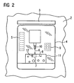
- FIG. 2 when the sliding door 2 is closed and the projection apparatus 3 is switched on, the view presented to a viewer through the pane 4 is shown on the working space 1 by way of example.
- the reference numerals 2, 3 and 4 are consistent with those of FIG.
- the operator is a virtual information field 5, which displays step by step the workflows, reflected.
- the operator is shown the next production step, which in the exemplary embodiment consists of the milling of a groove in the workpiece 11.
- the viewer can monitor the production or production process with high reliability in a simple manner.
- a spatial holographic representation is reflected, in which the representation visually penetrates into the working space 1 of the machine and thus visually merges with the physically existing machine elements and / or workpieces.
- the operator is given a very clear control option, in particular during startup, diagnostic and service processes but also during the normal production or production process.
- a virtual keyboard field 9 is also mirrored onto the pane 4.
- Operator actions on the virtual keypad 9 are visualized optically, e.g. recorded by means of a camera integrated in the projection apparatus 3 and provided to the control of the machine.
- the input field 9 and optionally further input fields which are no longer shown in FIG 2 for the sake of clarity, the machine can be controlled suburb by the operator.
- the operator actions can alternatively also be detected by means of a touch-sensitive disk, wherein the window of the viewing window can advantageously be pronounced the same as a touch-sensitive disk.
- other virtual input means e.g., virtual mouse
- the virtual keyboard field used in the embodiment are also conceivable.
- the head-up display formed from the disk 4 and the production apparatus 3 can either optionally be present as shown in FIG. 1 for the operator panel 10 or completely replace the operator panel 10, so that it can be dispensed with.
- the size of the display is limited in head-up technology essentially only by the available projection area ie the size of the disc. This gives a great deal of flexibility in terms of the size of the display, the type of display and the amount of simultaneously displayed Information. A scaling of the display according to the requirements of the machine and the wishes of the customer is easily possible.
- machine tools e.g. single or multi-axis turning, milling, drilling or grinding machines are to be understood.
- the machine tools also include machining centers, linear and rotary transfer machines, laser machines or gear cutting and gear cutting machines. All have in common is that a material is processed, this process can be performed multi-axially.
- To the production machines are e.g. Textile, plastic, wood, glass, ceramic or stone processing machines counted.
- Machines of forming technology, packaging technology, printing technology, conveyor technology, pump technology, fan technology, lifting tools and robots are also among the production machines.
Landscapes
- Engineering & Computer Science (AREA)
- Mechanical Engineering (AREA)
- Physics & Mathematics (AREA)
- Optics & Photonics (AREA)
- General Factory Administration (AREA)
- User Interface Of Digital Computer (AREA)
- Numerical Control (AREA)
Description
- Die Erfindung bezieht sich auf eine Werkzeug- oder Produktionsmaschine, wobei die Maschine einen mittels mindestens einer durchsichtigen Scheibe vom Bediener einsehbaren Arbeitsbereich aufweist.
- Fast jede handelsübliche Werkzeug- oder Produktionsmaschine besitzt heutzutage eine Anzeigeeinheit bzw. eine Bedientafel mit Hilfe derer der Fertigungs- bzw. Produktionsvorgang vor Ort parametriert und überwacht werden kann. Als Anzeigeeinheit wird dabei üblicherweise ein Röhren- oder LCD-Bildschirm eingesetzt. Dieser befindet sich gewöhnlich neben oder vor der Maschine als integraler Bestandteil einer Bedientafel oder ist an einem beweglichen sogenannten Galgen montiert.
- Die Erfindung beruht auf dem Gedanken, dass als Anzeigeeinheit ein Head-up-Display verwendet wird. Dabei kann das Head-up-Display zusätzlich zur handelsüblichen bestehenden konventionellen Anzeigeeinheit bzw. Bedientafel oder alternativ anstatt der herkömmlichen Anzeigeeinheit bzw. Bedientafel verwendet werden.
- Ein Head-up-Display ist eine technische Vorrichtung, mit Hilfe derer Information dem Bediener überlagert dargestellt werden können. Dabei wird das darzustellende Bild in eine durchsichtige Scheibe eingespiegelt, so dass sowohl das Bild, als auch der Hintergrund gleichzeitig sichtbar wird. Head-up-Displays kommen schon seit längerer Zeit in Flugzeugen zum Einsatz und befinden sich gerade in der Fahrzeugtechnik in der Einführungsphase.
- Der Arbeitsraum von Werkzeug- oder Produktionsmaschinen ist in der Regel gekapselt und mit mindestens einer Schutztür versehen. Der Arbeitsraum ist dabei in der Regel durch Sichtfenster bzw. durchsichtige Scheiben vom Bediener zu Kontrollzwecken einsehbar. Diese Sichtfenster ermöglichen somit die Überwachung des Fertigungs- bzw. Produktionsvorgangs durch den Bediener. Werden nun eines oder mehrere dieser Sichtfenster oder eine sonstige durchsichtige Abtrennung z.B. aus Glas oder durchsichtigen Kunststoff zum Arbeitsraum der Maschine als Head-up-Display verwendet, so ermöglicht die transparente Darstellung eine enge Bindung der dargestellten Information mit den im Hintergrund sichtbaren Arbeitsraum der Maschine. Diese Konzept eignet sich insbesondere besonders gut für innovative Ansätze bei Inbetriebnahme-, Fertigungs-, Produktions-, Diagnose- und Service-Vorgängen. Dabei besteht die Anforderung, Informationen möglichst gut in Verbindung zu Abläufen im Arbeitsraum der Maschine darzustellen. Durch eine sogenannte kontakt-analoge Darstellung können Informationen visualisiert werden, die in direktem Zusammenhang mit der durch sich überlagernden Umgebungsinformation stehen. Ein besonders hoher Vorteil kann gegebenenfalls durch eine räumlich holographische Darstellung erzielt werden, bei den die Anzeige optisch in den Arbeitsraum der Maschine eindringt und somit mit der Realität verschmilzt.
- Der Erfindung liegt daher die Aufgabe zugrunde, mit Hilfe eines Head-up-Displays dem Bediener eine besonders übersichtliche Darstellung von Informationen über den Fertigungs- bzw. Produktionsvorgang und sonstigen auf der Maschine ablaufenden Vorgängen zu ermöglichen.
- Diese Aufgabe wird durch eine Werkzeug- oder Produktionsmaschine nach Anspruch 1 gelöst.
- Durch die Integration eines Head-up-Displays in bestehende Maschinenkomponenten kann quasi die Anzeigeeinheit bzw. Bedientafel mit der Maschine verschmelzen. Durch die Platzersparnis und die Reduzierung der Komponenten lässt sich somit eine besonders kostengünstige Realisierung einer Anzeige- bzw. Bedientafel realisieren. Die Möglichkeit dem Bediener Informationen mit Hilfe der Head-up-Display-Technik in den Maschinenraum einzublenden ermöglicht grundlegende Innovation im Bereich der Inbetriebnahme, Produktion, Diagnostik und Service. So können beispielsweise Hinweise zu Fehlern beim Fertigungs- bzw. Produktionsvorgang direkt dort eingeblendet werden, wo sie aufgetreten sind. Weiterhin können Arbeitsanweisungen schrittweise bzw. arbeitsschrittabhängig direkt an der Maschine dargestellt werden, so dass diese wesentlich leichter nachvollzogen werden können als es bei einer abstrakten Darstellung an einem herkömmlichen Bildschirm der Fall wäre.
- Weiterhin zeichnet sich ein Head-up-Display gegenüber den vorher beschriebenen konventionellen Anzeigeeinheiten bzw. Bedientafeln durch seine besonders hohe Robustheit gegenüber den oft in der Fertigungstechnik vorkommenden problematischen Umweltbedingungen aus.
- Eine erste vorteilhafte Ausbildung der Erfindung ist dadurch gekennzeichnet, dass neben dem Visualisieren von Informationen, vom Bediener auch Daten und Befehle zur Steuerung der Maschine über die Scheibe eingebbar sind. Wenn der Head-up-Display neben den reinen Darstellungen von Informationen auch in der Lage ist, Daten und Befehle zur Steuerung der Maschine zu erfassen, kann mittels des Head-up-Displays die herkömmliche Bedientafel ersetzt werden.
- In diesem Zusammenhang erweist es sich als vorteilhaft, wenn die vom Bediener eingegebenen Daten und Befehle über mindestens eine Kamera oder mittels einer berührungsempfindlichen Scheibe erfassbar sind. Die eingegebenen Daten und Befehle können solchermaßen besonders sicher erfasst werden.
- Ferner erweist es sich als vorteilhaft wenn der Projektionsapparat an der Maschinenaußenseite angebracht ist, da an der Maschinenaußenseite keine so ungünstigen Umweltbedingungen für die Funktionsfähigkeit des Projektionsapparates z.B. hinsichtlich Verschmutzung gegeben sind, wie an der Maschineninnenseite.
- Weiterhin er weist es sich als vorteilhaft, wenn als Informationen Betriebsparameter und/oder Arbeitsanweisungen und/oder die graphische Visualisierung von Simulationsergebnissen und/oder die graphische Visualisierung von Arbeitsabläufen vorgesehen sind. Solche Informationen sind für ein Verständnis und Kontrolle des Fertigungs- bzw. Produktionsvorgangs für den Bediener von hohem Interesse.
- Ferner erweist es sich als vorteilhaft, wenn vom Head-up-Display eine räumliche holographische Darstellung, die virtuell in den Arbeitsraum der Maschine eindringt, erzeugbar ist. Durch eine räumliche holographische Darstellung, die virtuell in den Arbeitsraum der Maschine eindringt, ist dem Bediener eine besonders übersichtliche optische Kontrolle und Darstellung des Fertigungs- bzw. Produktionsvorgangs möglich.
- Ein Ausführungsbeispiel der Erfindung ist in der Zeichnung dargestellt und wird im folgenden näher erläutert. Dabei zeigen:
- FIG 1
- eine erfindungsgemäße Werkzeugmaschine und
- FIG 2
- eine Darstellung des Head-up-Displays.
- In FIG 1 ist in Form eines Ausführungsbeispiels eine erfindungsgemäße Werkzeugmaschine dargestellt. Der Arbeitsraum 1 der Maschine, in dem der eigentliche Fertigungs- bzw. Produktionsvorgang stattfindet ist im geschlossenen Zustand durch die Schiebetür 2 vom Bediener der Maschine getrennt. In FIG 1 ist die Maschine mit geöffneter Schiebetür 2 dargestellt.
- Mittels einer Bedientafel 10 kann die Maschine Vorort bedient werden.
- In die Schiebetür 2 ist eine durchsichtige Scheibe 4, die in dem Ausführungsbeispiel aus Glas besteht, eingelassen. Bei geschlossener Schiebetür 2 ermöglicht die Scheibe 4 den Bediener, die Sicht auf den Arbeitsraum 1. Über der Scheibe 4 befindet sich an der Maschinenaußenseite der Schiebetür 2 ein Projektionsapparat 3. Mit Hilfe des Projektionsapparates 3 wird auf die durchsichtige Scheibe 4 das darzustellende Bild eingespiegelt, so dass sowohl das Bild, als auch der Hintergrund einem Betrachter gleichzeitig sichtbar wird.
- In FIG 2 ist beispielhaft bei geschlossener Schiebetür 2 und angeschaltetem Projektionsapparat 3, die einem Betrachter sich bietende Sicht durch die Scheibe 4 auf den Arbeitsraum 1 dargestellt. Die Bezugszeichen 2, 3 und 4 stimmen mit den aus FIG 1 überein. Durch die Scheibe 4 ist das eingespannte Fräswerkzeug 10 sowie das zu bearbeitende Werkstück 11 erkennbar. Über den Projektionsapparat 3 wird nun auf die Scheibe 4 dem Bediener zusätzliche Informationen eingespiegelt. In den Ausführungsbeispiel wird dem Bediener ein virtuelles Informationsfeld 5, welches schrittweise die Arbeitsabläufe anzeigt, eingespiegelt. Über die vom Projektionsapparat 3 eingespiegelten Pfeile 6, 8 dem eingespiegelten Ausschnitt 7 sowie der eingespiegelten Bemaßung 12, wird dem Bediener der nächste Produktionsschritt dargestellt, der in dem Ausführungsbeispiel aus dem Ausfräsen einer Nut im Werkstück 11 besteht. Anhand dieser virtuell eingespiegelten übersichtlichen Information kann der Betrachter den Fertigungs- bzw. Produktionsvorgang mit hoher Zuverlässigkeit auf einfache Art und Weise überwachen.
- Besonders vorteilhaft ist es wenn zusätzlich auf die Scheibe 4, mittels des Projektionsapparates 3, eine räumliche holographische Darstellung eingespiegelt wird, bei dem die Darstellung optisch in den Arbeitsraum 1 der Maschine eindringt und solchermaßen mit den physikalisch vorhandenen Maschinenelementen und/oder Werkstücken optisch verschmilzt. Auf diese Weise ist dem Bediener insbesondere bei Inbetriebnahme-, Diagnose- und Servicevorgängen aber auch während des normalen Fertigungs- bzw. Produktionsvorgangs eine sehr übersichtliche Kontrollmöglichkeit gegeben.
- Zusätzlich wird im Ausführungsbeispiel mittels des Projektionsapparates 3 auch noch ein virtuelles Tastaturfeld 9 auf die Scheibe 4 eingespiegelt. Bedienhandlungen am virtuellen Tastaturfeld 9 werden optisch z.B. mittels einer in den Projektionsapparat 3 integrierten Kamera erfasst und der Steuerung der Maschine zur Verfügung gestellt. Mittels des Eingabefeldes 9 und gegebenenfalls noch weiteren Eingabefeldern, die der Übersichtlichkeit halber in FIG 2 nicht mehr dargestellt sind, lässt sich die Maschine Vorort vom Bediener steuern.
- Selbstverständlich können die Bedienhandlungen bei einem oder mehreren virtuellen Tastaturfeldern alternativ auch mittels einer berührungsempfindlichen Scheibe erfasst werden, wobei die Scheibe des Sichtfensters vorteilhaft gleich als berührungsempfindliche Scheibe ausgeprägt sein kann. Weiterhin sind selbstverständlich auch noch andere virtuelle Eingabemittel (z.B. virtuelle Maus) als das im Ausführungsbeispiel verwendete virtuelle Tastaturfeld denkbar.
- Der aus der Scheibe 4 und dem Produktionsapparat 3 gebildete Head-up-Display kann entweder optional, wie in FIG 1 dargestellt, zur Bedientafel 10 vorhanden sein oder die Bedientafel 10 komplett ersetzen, so dass diese entfallen kann.
- Die Größe des Displays ist bei Head-up-Technik im wesentlichen nur durch die zur Verfügung stehende Projektionsfläche d.h. die Größe der Scheibe beschränkt. Dadurch ergibt sich eine große Flexibilität bezüglich der Größe der Anzeige, der Art der Anzeige und der Menge der gleichzeitig dargestellten Informationen. Eine Skalierung der Anzeige gemäß den Anforderungen der Maschine und der Wünsche des Kunden ist problemlos möglich.
- Selbstverständlich können mit Hilfe des Head-up-Displays auch im Vorfeld extern erzeugte Simulationsergebnisse eingespielt werden und solchermaßen im Arbeitsraum der Maschine der Produktionsvorgang visuell kontrolliert werden. Eventuell vorhandene Fehler sind somit leicht erkennbar.
- An dieser Stelle sei angemerkt, dass als Werkzeugmaschinen z.B. ein- oder mehrachsige Dreh-, Fräs-, Bohr- oder Schleifmaschinen zu verstehen sind. Zu den Werkzeugmaschinen werden auch noch Bearbeitungszentren, lineare und rotatorische Transfermaschinen, Lasermaschinen oder Wälz- und Verzahnmaschinen gezählt. Allen gemeinsam ist, dass ein Material bearbeitet wird, wobei diese Bearbeitung mehrachsig ausgeführt werden kann. Zu den Produktionsmaschinen werden z.B. Textil-, Kunststoff-, Holz-, Glas-, Keramik- oder Steinbearbeitungsmaschinen gezählt. Maschinen der Umformtechnik, Verpackungstechnik, Drucktechnik, Fördertechnik, Pumpentechnik, Lüftertechnik, Hebewerkzeuge sowie Roboter gehören ebenfalls zu den Produktionsmaschinen.
Claims (6)
- Werkzeug- oder Produktionsmaschine, wobei die Maschine einen mittels mindestens einer durchsichtigen Scheibe (4) vom Bediener einsehbaren Arbeitsbereich (1) aufweist, dadurch gekennzeichnet, dass die Maschine ein Projektions apparat aufweist, und die Scheibe mittels des Projektionsapparates (3) als Head-up-Display verwendbar ist und solchermaßen dem Bediener Informationen auf der Scheibe (4) visualisierbar sind.
- Werkzeug- oder Produktionsmaschine nach Anspruch 1, dadurch gekennzeichnet, dass neben dem Visualisieren von Informationen, vom Bediener auch Daten und Befehle zur Steuerung der Maschine über die Scheibe (4) eingebbar sind.
- Werkzeug- oder Produktionsmaschine nach Anspruch 2, dadurch gekennzeichnet, dass die vom Bediener eingegebenen Daten und Befehle über mindestens eine Kamera oder mittels einer berührungsempfindlichen Scheibe (4) erfassbar sind.
- Werkzeug- oder Produktionsmaschine nach einem der vorhergehenden Ansprüche, dadurch gekennzeichnet, dass der Projektionsapparat (3) an der Maschinenaußenseite angebracht ist.
- Werkzeug- oder Produktionsmaschine nach einem der vorhergehenden Ansprüche, dadurch gekennzeichnet, dass als Informationen Betriebsparameter und/oder Arbeitsanweisungen und/oder die graphische Visualisierung von Simulationsergebnissen und/oder die graphische Visualisierung von Arbeitsabläufen vorgesehen sind.
- Werkzeug- oder Produktionsmaschine nach einem der vorhergehenden Ansprüche, dadurch gekennzeichnet, dass vom Head-up-Display eine räumliche holographische Darstellung, die virtuell in den Arbeitsraum (1) der Maschine eindringt, erzeugbar ist.
Applications Claiming Priority (2)
| Application Number | Priority Date | Filing Date | Title |
|---|---|---|---|
| DE10325895A DE10325895A1 (de) | 2003-06-06 | 2003-06-06 | Werkzeug- oder Produktionsmaschine mit Head-up-Display |
| DE10325895 | 2003-06-06 |
Publications (2)
| Publication Number | Publication Date |
|---|---|
| EP1484133A1 EP1484133A1 (de) | 2004-12-08 |
| EP1484133B1 true EP1484133B1 (de) | 2006-07-12 |
Family
ID=33154589
Family Applications (1)
| Application Number | Title | Priority Date | Filing Date |
|---|---|---|---|
| EP04011545A Expired - Lifetime EP1484133B1 (de) | 2003-06-06 | 2004-05-14 | Werkzeug- oder Produktionsmaschine mit durchsichtiger Scheibe und Head-up-Display |
Country Status (3)
| Country | Link |
|---|---|
| US (1) | US7296956B2 (de) |
| EP (1) | EP1484133B1 (de) |
| DE (2) | DE10325895A1 (de) |
Families Citing this family (41)
| Publication number | Priority date | Publication date | Assignee | Title |
|---|---|---|---|---|
| JP4048090B2 (ja) * | 2002-08-28 | 2008-02-13 | 住友重機械工業株式会社 | 歯車加工シミュレーション方法、歯車加工シミュレーションプログラム及び歯車加工シミュレーション装置 |
| JP2005305602A (ja) * | 2004-04-22 | 2005-11-04 | Fanuc Ltd | 工作機械 |
| GB2419857A (en) * | 2004-11-04 | 2006-05-10 | Thomas Smith Blackhurst | Transparent instument panel |
| DE102005014947A1 (de) * | 2005-04-01 | 2006-10-26 | E. Zoller GmbH & Co. KG Einstell- und Messgeräte | Werkzeugmess- und/oder Einstellgerät mit einer Bilderfassungseinheit |
| DE102005038718B3 (de) * | 2005-08-15 | 2006-08-31 | Uhlmann Pac-Systeme Gmbh & Co. Kg | Verpackungsmaschine |
| US8399815B2 (en) * | 2006-08-04 | 2013-03-19 | Ajax Tocco Magnethermic Corporation | Apparatus and method for hardening bearing surfaces of a crankshaft |
| US8642932B2 (en) * | 2006-08-04 | 2014-02-04 | Ajax Tocco Magnethermic Corporation | System and method for crankshaft hardening |
| US8652040B2 (en) * | 2006-12-19 | 2014-02-18 | Valencell, Inc. | Telemetric apparatus for health and environmental monitoring |
| DE102007001266A1 (de) | 2007-01-08 | 2008-07-10 | Metaio Gmbh | Optische Anordnung, insbesondere für ein Head-Up-Display |
| DE102013005743B4 (de) * | 2013-04-05 | 2021-03-18 | Fresenius Medical Care Deutschland Gmbh | Vorrichtung und Verfahren zur Unterstützung der Bedienung von medizintechnischen Geräten |
| DE102013015024A1 (de) * | 2013-09-10 | 2015-03-12 | Liebherr-Verzahntechnik Gmbh | Verzahnmaschine |
| DE102013015239A1 (de) * | 2013-09-13 | 2015-03-19 | Liebherr-Verzahntechnik Gmbh | Verfahren zum Rüsten einer Verzahnmaschine sowie Verzahnmaschine |
| FR3011944B1 (fr) * | 2013-10-10 | 2017-03-17 | Sidel Participations | Systeme de commande d'une machine industrielle a interface tactile integree a un panneau de confinement |
| FR3011943B1 (fr) * | 2013-10-10 | 2017-03-24 | Sidel Participations | Systeme de commande d'une machine industrielle a interface tactile integree a une vitre |
| DE102014000789A1 (de) * | 2014-01-22 | 2015-07-23 | Mimot Gmbh | Werkzeugmaschine mit Displayvorrichtung |
| US10431330B2 (en) * | 2014-01-22 | 2019-10-01 | Children's Hospital & Research Center At Oakland | Method and system to provide patient information and facilitate care of a patient |
| EP2913730B1 (de) | 2014-02-28 | 2019-10-30 | ABB Schweiz AG | Verwendung eines Live-Video-Streams in einem Prozesssteuerungssystem |
| FR3020891B1 (fr) * | 2014-05-09 | 2022-04-08 | Dassault Aviat | Procede de simulation d'un montage et/ou d'une utilisation d'un ensemble fonctionnel de plate-forme, et systeme associe |
| DE102014209367A1 (de) * | 2014-05-16 | 2015-11-19 | Siemens Aktiengesellschaft | Prozessvisualisierungsvorrichtung und Verfahren zum Anzeigen von Prozessen wenigstens einer Maschine oder Anlage |
| US20160040469A1 (en) * | 2014-08-06 | 2016-02-11 | Ben Lietz | Methods and Systems to Indicate the Status of Door Operations |
| EP3068002B1 (de) | 2015-03-12 | 2019-11-06 | Schleuniger Holding AG | Kabelbearbeitungsmaschine mit verbessertem genauigkeitsmechanismus zur kabelverarbeitung |
| EP3067769B1 (de) | 2015-03-12 | 2017-10-04 | Schleuniger Holding AG | Kabelbearbeitungsmaschinenüberwachung mit verbessertem genauigkeitsmechanismus zur kabelverarbeitung |
| JP5906336B1 (ja) * | 2015-03-23 | 2016-04-20 | Ckd株式会社 | 製造装置 |
| DE102015215625A1 (de) * | 2015-08-17 | 2017-02-23 | Schaeffler Technologies AG & Co. KG | Montage- und/oder Bearbeitungsmaschine, damit gebildete Fertigungsstraße sowie Fertigungsanlage |
| DE102016215860A1 (de) | 2016-08-24 | 2018-03-01 | Siemens Aktiengesellschaft | Trackingloses projektionsbasiertes "Augmented Reality [AR]"-Verfahren und -System zur Montageunterstützung von Produktionsgütern, insbesondere zum Lokalisieren von Nutensteinen für die Bauteilmontage im Waggonbau |
| WO2018047315A1 (ja) * | 2016-09-09 | 2018-03-15 | マキノジェイ株式会社 | 表示装置を備えた工作機械 |
| WO2018142547A1 (ja) * | 2017-02-02 | 2018-08-09 | 株式会社Fuji | 実装関連装置 |
| DE102017206600A1 (de) * | 2017-04-19 | 2018-10-25 | Robert Bosch Gmbh | Werkzeug- oder Produktionseinrichtung |
| CN107877252A (zh) * | 2017-11-28 | 2018-04-06 | 宁夏共享机床辅机有限公司 | 一种用于机床防护罩的探测保护组件 |
| JP7157574B2 (ja) * | 2018-07-05 | 2022-10-20 | 株式会社ディスコ | 加工装置 |
| CN109015112A (zh) * | 2018-10-17 | 2018-12-18 | 苏州市斯可源自动化科技有限公司 | 一种机床防护门 |
| EP3695804B1 (de) * | 2019-02-13 | 2021-10-20 | DGSHAPE Corporation | Statusanzeigevorrichtung, statusanzeigeverfahren und statusanzeigesystem für eine zahnärztliche verarbeitungsmaschine |
| JP7233947B2 (ja) * | 2019-02-13 | 2023-03-07 | Dgshape株式会社 | デンタル加工機のエラー履歴表示システム |
| EP3709006A1 (de) * | 2019-03-15 | 2020-09-16 | Primetals Technologies France SAS | Sichtkontrollsystem für ein ausgebreitetes produkt |
| DE102019117092A1 (de) * | 2019-06-25 | 2020-12-31 | Kiefel Gmbh | Produktionsmaschine mit steuerungsprogramm |
| DE102020212162A1 (de) | 2020-09-28 | 2022-03-31 | Siemens Aktiengesellschaft | Einhausung für eine Herstellungs-Maschine und/oder einen Teil einer Fertigungsstraße sowie System zur Steuerung und/oder Regelung einer Fertigungsanlage |
| JP7846645B2 (ja) * | 2021-12-22 | 2026-04-15 | Dmg森精機株式会社 | 工作機械 |
| IT202100033101A1 (it) * | 2021-12-30 | 2023-06-30 | Scm Group Spa | Macchina per la lavorazione di pezzi in legno comprendente un dispositivo di interfaccia. |
| EP4209844A1 (de) * | 2022-01-11 | 2023-07-12 | Hilti Aktiengesellschaft | Werkzeugmaschine mit automatischer anzeige von betriebsparametern |
| DE102023105146A1 (de) | 2023-03-02 | 2024-09-05 | Gebr. Heller Maschinenfabrik Gmbh | Werkzeugmaschine mit Einfahr-Assistent |
| CN119973725B (zh) * | 2025-04-17 | 2025-07-25 | 浙江大学 | 一种机床动态优化运动变量测量装置 |
Family Cites Families (18)
| Publication number | Priority date | Publication date | Assignee | Title |
|---|---|---|---|---|
| US2481381A (en) * | 1946-04-25 | 1949-09-06 | Cleveland Grinding Machine Com | Optical projection viewer for machine tools |
| US2591227A (en) * | 1951-03-15 | 1952-04-01 | Banko George | Counterbalance for optical projection viewer for machine tools |
| US4884145A (en) * | 1986-12-31 | 1989-11-28 | Loral Corporation | Alignment of double eccentric aiming system for solid state camera |
| US5394521A (en) * | 1991-12-09 | 1995-02-28 | Xerox Corporation | User interface with multiple workspaces for sharing display system objects |
| US5096281A (en) * | 1987-10-21 | 1992-03-17 | Optical Profile, Inc. | Optical transform system |
| DE3927712A1 (de) * | 1989-08-22 | 1991-02-28 | Boehringer Werkzeugmaschinen | Schutzabdeckung |
| DE4029312A1 (de) * | 1990-09-15 | 1992-03-19 | Claas Ohg | Anzeigevorrichtung fuer betriebsdaten auf einer sichtscheibe |
| US5291316A (en) * | 1991-09-27 | 1994-03-01 | Astronautics Corporation Of America | Information display system having transparent holographic optical element |
| JP3251363B2 (ja) | 1992-02-17 | 2002-01-28 | 株式会社小松製作所 | タッチスクリーン表示装置 |
| US5818455A (en) * | 1993-07-21 | 1998-10-06 | Xerox Corporation | Method and apparatus for operating on the model data structure of an image to produce human perceptible output using a viewing operation region having explicit multiple regions |
| DE19708240C2 (de) * | 1997-02-28 | 1999-10-14 | Siemens Ag | Anordnung und Verfahren zur Detektion eines Objekts in einem von Wellen im nichtsichtbaren Spektralbereich angestrahlten Bereich |
| JPH11156677A (ja) | 1997-11-21 | 1999-06-15 | Hitachi Seiki Co Ltd | 工作機械の加工情報投影装置 |
| US6301007B1 (en) * | 1998-05-29 | 2001-10-09 | The Regents Of The University Of California | Machine tool locator |
| WO2000052541A1 (de) * | 1999-03-02 | 2000-09-08 | Siemens Aktiengesellschaft | System und verfahren zur situationsgerechten unterstützung der interaktion mit hilfe von augmented-reality-technologien |
| US6179426B1 (en) * | 1999-03-03 | 2001-01-30 | 3M Innovative Properties Company | Integrated front projection system |
| US6456438B1 (en) * | 1999-08-12 | 2002-09-24 | Honeywell Inc. | Variable immersion vignetting display |
| DE10144075B4 (de) * | 2001-09-07 | 2005-05-12 | Siemens Ag | Head-Up-Display |
| EP1512283B1 (de) * | 2002-06-12 | 2008-05-21 | Silicon Optix Inc. | Bildprojektionssystem und -verfahren für kurze Reichweiten |
-
2003
- 2003-06-06 DE DE10325895A patent/DE10325895A1/de not_active Withdrawn
-
2004
- 2004-05-14 EP EP04011545A patent/EP1484133B1/de not_active Expired - Lifetime
- 2004-05-14 DE DE502004000940T patent/DE502004000940D1/de not_active Expired - Lifetime
- 2004-06-04 US US10/862,017 patent/US7296956B2/en not_active Expired - Lifetime
Also Published As
| Publication number | Publication date |
|---|---|
| DE502004000940D1 (de) | 2006-08-24 |
| DE10325895A1 (de) | 2005-01-05 |
| US20050002151A1 (en) | 2005-01-06 |
| EP1484133A1 (de) | 2004-12-08 |
| US7296956B2 (en) | 2007-11-20 |
Similar Documents
| Publication | Publication Date | Title |
|---|---|---|
| EP1484133A1 (de) | Werkzeug- oder Produktionsmaschine mit durchsichtiger Scheibe und Head-up-Display | |
| WO2004108348A2 (de) | Werkzeug- oder produktionsmaschine mit anzeigeeinheit zur visualisierung von arbeitsabläufen | |
| EP1932618B2 (de) | Arbeitsmaschine | |
| DE102015204487A1 (de) | Simulationseinrichtung zur manuellen betätigung einer werkzeugmaschine | |
| DE102010036499A1 (de) | Werkzeugvektor-Anzeigevorrichtung für eine Werkzeugmaschine mit Drehachse | |
| EP2124117A1 (de) | Bedieneinrichtung zur Bedienung einer Werkzeugmaschine | |
| EP2629187B1 (de) | Verfahren zur Anpassung der graphischen Darstellung auf der Bedienoberfläche einer Computeranwenderstation | |
| DE102013015024A1 (de) | Verzahnmaschine | |
| DE102017108492A1 (de) | Steuervorrichtung eines Roboters, die ein Betriebsprogramm, in dem der Zustand einer zusätzlichen Achse enthalten ist, anzeigt | |
| DE10359251A1 (de) | Vorrichtung zur Automatisierung von Werkzeug- oder Produktionsmaschinen | |
| EP0858016B1 (de) | Numerische Steuerung mit Bedienoberfläche in Fenstertechnik | |
| DE102014000789A1 (de) | Werkzeugmaschine mit Displayvorrichtung | |
| EP3168701A1 (de) | Verfahren zur darstellung der bearbeitung in einer werkzeugmaschine | |
| EP1969435B1 (de) | Vorrichtung zum steuern mindestens einer maschine | |
| EP1183577B1 (de) | Verfahren zur erzeugung eines steuerbausteins und steuerbaustein | |
| EP1655663A1 (de) | Datenflussmodellierung in Engineering-Systemen | |
| EP2048677A9 (de) | Bedieneinrichtung zur Bedienung einer Werkzeugmaschine, Produktionsmaschine und/oder eines Roboters | |
| WO2020161300A1 (de) | Bedienungsvorrichtung und verfahren | |
| EP0530384B1 (de) | Werkzeugmaschinensteuerung zur gleichzeitigen Bearbeitung von plattenförmigen Werkstücken mit mehreren Werkzeugen | |
| EP2921921A1 (de) | Verfahren zum Betrieb einer Bedienungseinrichtung eines Automatisierungsgeräts | |
| EP2078994A1 (de) | Automatisierungsgerät und Verfahren zu dessen Betrieb | |
| WO2024064989A1 (de) | Anzeigevorrichtung und steuerungssystem für potentiell gefahrbringende technische systeme | |
| DE102023105146A1 (de) | Werkzeugmaschine mit Einfahr-Assistent | |
| DE102004056246C5 (de) | Anzeigeeinrichtung für ein Elektronikgerät | |
| DE102024122756A1 (de) | Kamerabasierte und/oder projektionsbasierte montageunterstützung |
Legal Events
| Date | Code | Title | Description |
|---|---|---|---|
| PUAI | Public reference made under article 153(3) epc to a published international application that has entered the european phase |
Free format text: ORIGINAL CODE: 0009012 |
|
| AK | Designated contracting states |
Kind code of ref document: A1 Designated state(s): AT BE BG CH CY CZ DE DK EE ES FI FR GB GR HU IE IT LI LU MC NL PL PT RO SE SI SK TR |
|
| AX | Request for extension of the european patent |
Extension state: AL HR LT LV MK |
|
| 17P | Request for examination filed |
Effective date: 20050120 |
|
| AKX | Designation fees paid |
Designated state(s): DE FR GB |
|
| GRAP | Despatch of communication of intention to grant a patent |
Free format text: ORIGINAL CODE: EPIDOSNIGR1 |
|
| GRAS | Grant fee paid |
Free format text: ORIGINAL CODE: EPIDOSNIGR3 |
|
| GRAA | (expected) grant |
Free format text: ORIGINAL CODE: 0009210 |
|
| AK | Designated contracting states |
Kind code of ref document: B1 Designated state(s): DE FR GB |
|
| REG | Reference to a national code |
Ref country code: GB Ref legal event code: FG4D Free format text: NOT ENGLISH |
|
| GBT | Gb: translation of ep patent filed (gb section 77(6)(a)/1977) |
Effective date: 20060802 |
|
| REF | Corresponds to: |
Ref document number: 502004000940 Country of ref document: DE Date of ref document: 20060824 Kind code of ref document: P |
|
| ET | Fr: translation filed | ||
| PLBE | No opposition filed within time limit |
Free format text: ORIGINAL CODE: 0009261 |
|
| STAA | Information on the status of an ep patent application or granted ep patent |
Free format text: STATUS: NO OPPOSITION FILED WITHIN TIME LIMIT |
|
| 26N | No opposition filed |
Effective date: 20070413 |
|
| PGFP | Annual fee paid to national office [announced via postgrant information from national office to epo] |
Ref country code: GB Payment date: 20090514 Year of fee payment: 6 |
|
| GBPC | Gb: european patent ceased through non-payment of renewal fee |
Effective date: 20100514 |
|
| PG25 | Lapsed in a contracting state [announced via postgrant information from national office to epo] |
Ref country code: GB Free format text: LAPSE BECAUSE OF NON-PAYMENT OF DUE FEES Effective date: 20100514 |
|
| REG | Reference to a national code |
Ref country code: FR Ref legal event code: PLFP Year of fee payment: 13 |
|
| REG | Reference to a national code |
Ref country code: FR Ref legal event code: PLFP Year of fee payment: 14 |
|
| REG | Reference to a national code |
Ref country code: FR Ref legal event code: PLFP Year of fee payment: 15 |
|
| PGFP | Annual fee paid to national office [announced via postgrant information from national office to epo] |
Ref country code: FR Payment date: 20210526 Year of fee payment: 18 |
|
| PGFP | Annual fee paid to national office [announced via postgrant information from national office to epo] |
Ref country code: DE Payment date: 20210720 Year of fee payment: 18 |
|
| REG | Reference to a national code |
Ref country code: DE Ref legal event code: R119 Ref document number: 502004000940 Country of ref document: DE |
|
| PG25 | Lapsed in a contracting state [announced via postgrant information from national office to epo] |
Ref country code: FR Free format text: LAPSE BECAUSE OF NON-PAYMENT OF DUE FEES Effective date: 20220531 |
|
| PG25 | Lapsed in a contracting state [announced via postgrant information from national office to epo] |
Ref country code: DE Free format text: LAPSE BECAUSE OF NON-PAYMENT OF DUE FEES Effective date: 20221201 |