EP1484073A1 - Recovering implement - Google Patents
Recovering implement Download PDFInfo
- Publication number
- EP1484073A1 EP1484073A1 EP03710338A EP03710338A EP1484073A1 EP 1484073 A1 EP1484073 A1 EP 1484073A1 EP 03710338 A EP03710338 A EP 03710338A EP 03710338 A EP03710338 A EP 03710338A EP 1484073 A1 EP1484073 A1 EP 1484073A1
- Authority
- EP
- European Patent Office
- Prior art keywords
- liquid
- needle tube
- container body
- storing space
- recovering
- Prior art date
- Legal status (The legal status is an assumption and is not a legal conclusion. Google has not performed a legal analysis and makes no representation as to the accuracy of the status listed.)
- Withdrawn
Links
Images



Classifications
-
- A—HUMAN NECESSITIES
- A61—MEDICAL OR VETERINARY SCIENCE; HYGIENE
- A61J—CONTAINERS SPECIALLY ADAPTED FOR MEDICAL OR PHARMACEUTICAL PURPOSES; DEVICES OR METHODS SPECIALLY ADAPTED FOR BRINGING PHARMACEUTICAL PRODUCTS INTO PARTICULAR PHYSICAL OR ADMINISTERING FORMS; DEVICES FOR ADMINISTERING FOOD OR MEDICINES ORALLY; BABY COMFORTERS; DEVICES FOR RECEIVING SPITTLE
- A61J1/00—Containers specially adapted for medical or pharmaceutical purposes
- A61J1/14—Details; Accessories therefor
- A61J1/20—Arrangements for transferring or mixing fluids, e.g. from vial to syringe
- A61J1/2089—Containers or vials which are to be joined to each other in order to mix their contents
-
- A—HUMAN NECESSITIES
- A61—MEDICAL OR VETERINARY SCIENCE; HYGIENE
- A61J—CONTAINERS SPECIALLY ADAPTED FOR MEDICAL OR PHARMACEUTICAL PURPOSES; DEVICES OR METHODS SPECIALLY ADAPTED FOR BRINGING PHARMACEUTICAL PRODUCTS INTO PARTICULAR PHYSICAL OR ADMINISTERING FORMS; DEVICES FOR ADMINISTERING FOOD OR MEDICINES ORALLY; BABY COMFORTERS; DEVICES FOR RECEIVING SPITTLE
- A61J1/00—Containers specially adapted for medical or pharmaceutical purposes
- A61J1/14—Details; Accessories therefor
- A61J1/20—Arrangements for transferring or mixing fluids, e.g. from vial to syringe
- A61J1/2096—Combination of a vial and a syringe for transferring or mixing their contents
-
- A—HUMAN NECESSITIES
- A61—MEDICAL OR VETERINARY SCIENCE; HYGIENE
- A61J—CONTAINERS SPECIALLY ADAPTED FOR MEDICAL OR PHARMACEUTICAL PURPOSES; DEVICES OR METHODS SPECIALLY ADAPTED FOR BRINGING PHARMACEUTICAL PRODUCTS INTO PARTICULAR PHYSICAL OR ADMINISTERING FORMS; DEVICES FOR ADMINISTERING FOOD OR MEDICINES ORALLY; BABY COMFORTERS; DEVICES FOR RECEIVING SPITTLE
- A61J1/00—Containers specially adapted for medical or pharmaceutical purposes
- A61J1/14—Details; Accessories therefor
- A61J1/20—Arrangements for transferring or mixing fluids, e.g. from vial to syringe
- A61J1/2003—Accessories used in combination with means for transfer or mixing of fluids, e.g. for activating fluid flow, separating fluids, filtering fluid or venting
- A61J1/2006—Piercing means
- A61J1/201—Piercing means having one piercing end
-
- A—HUMAN NECESSITIES
- A61—MEDICAL OR VETERINARY SCIENCE; HYGIENE
- A61M—DEVICES FOR INTRODUCING MEDIA INTO, OR ONTO, THE BODY; DEVICES FOR TRANSDUCING BODY MEDIA OR FOR TAKING MEDIA FROM THE BODY; DEVICES FOR PRODUCING OR ENDING SLEEP OR STUPOR
- A61M5/00—Devices for bringing media into the body in a subcutaneous, intra-vascular or intramuscular way; Accessories therefor, e.g. filling or cleaning devices, arm rests
- A61M5/178—Syringes
- A61M5/31—Details
- A61M2005/3123—Details having air entrapping or venting means, e.g. purging channels in pistons
Definitions
- the present invention relates to a recovering instrument, and particularly to a recovering instrument for recovering excessive chemical liquid and interfusing gas from a liquid-filled container such as, for example, a pre-filled syringe.
- the pre-filled syringe generally has a structure in which a syringe comprises an outer tube having a mouth portion wherein its diameter is reduced on the tip end side thereof, a gasket inserted in the outer tube via the base end opening of the outer tube, and a pusher (plunger rod) connected to the gasket, and a powdery chemical or chemical liquid is stored in a sealed condition in the space surrounded by the outer tube of the syringe and the tip end surface of the gasket of the syringe.
- the mouth portion is sealed with a sealing member such as an elastic membrane, and, when needed, the elastic membrane is punctured by a needle tube and the pusher is operated, whereby an infusion is introduced into the outer tube via the needle tube or a chemical liquid in the outer tube is discharged.
- a sealing member such as an elastic membrane
- the pre-filled syringe is excellent in safety and simplicity, in view of that there is no need for an operation to transfer the chemical or chemical liquid stored therein into the syringe. Therefore, a shift to the pre-filled syringe, as a chemical storing form for replacing vial or ampule, has been contrived widely. In recent years, a shift to storage of a carcinostatic agent or the like in a pre-filled syringe has been desired and has come to be put to practical use.
- a needle tube is attached to the pre-filled syringe, and air (bubbles) interfusing into the pre-filled syringe and excessive chemical liquid in the pre-filled syringe are discharged.
- the chemical liquid and the like thus discharged are received by a tray or the like, and are not recovered into a closed space.
- a chemical liquid not suited to jetting into the air such as a carcinostatic agent
- a discharging operation is unsuitable for the operator.
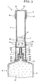
- FIGS. 1 and 2 are partly sectional plan views showing one embodiment of the recovering instrument according to the present invention, in the disassembled state and in the assembled state, respectively, and FIGS. 3 and 4 are vertical sectional views showing an operation in use of the recovering instrument shown in FIGS. 1 and 2, respectively.
- the upper side in FIGS. 1 to 4 will be referred to as “the base end”, and the lower side as “the tip end”.
- the recovering instrument 1 is an instrument for recovering excessive liquid and interfusing gas (liquid and gas recovering instrument) from a liquid-filled container not including a needle tube in itself, for example, a syringe (pre-filled syringe) 8 shown in FIGS. 3 and 4.
- the recovering instrument 1 in this embodiment is composed of a hard container body 2, a needle tube 3 disposed at the tip end of the container body 2, a gasket 4 disposed slidably in the container body 2, an enclosing member 5 for enclosing the needle tube 3, a cap 6 mounted to a base end portion of the container body 2, and a holder 7 mounted to a tip end portion of the container body 2.
- the container body 2 is in a bottomed tubular shape a base end portion 25 of which is open whereas the tip end side of which is closed with a bottom plate 23 having an opening 24 in its central portion.
- the material constituting the container body 2 include comparatively hard resin materials such as polyvinyl chloride, polyethylene, polypropylene, cyclic polyolefins, polystyrene, poly-(4-methylpentene-1), polycarbonate, acrylic resin, polysulfone, polyphenylsulfone, polyether sulfone, polyarylate resins, polymethyl methacrylate, acrylonitrile-butadiene-styrene copolymer, polyesters such as polyethylene terephthalate, and polyethylene naphthalate, butadiene-styrene copolymer, polyamides (e.g., nylon 6, nylon 6 ⁇ 6, nylon 6 ⁇ 10, nylon 12), etc., and various glass materials.
- resins as polyvinyl chloride, poly
- the container body 2 is provided, at the outer circumference of a base end portion thereof, with a ring-like projected portion 21 for fitting to the cap 6, over the entire circumference thereof.
- the container body 2 is provided, at the outer circumference of a tip end portion thereof, with a male screw 22 for mounting the holder 7 thereto by screw engagement.
- a projected portion for fitting of the holder 7 may be provided on the circular circumference.
- the needle tube (hollow needle) 3 is erected on a central portion of a bottom plate 23 of the container body 2, substantially perpendicular to the bottom plate 23.
- An inner cavity 31 of the needle tube 3 is communicated with a storing space 20 via the opening 24.
- the needle tube 3 is formed of the same resin material as that for the container body 2 integrally with the container body 2 in this embodiment, the needle tube 3 is not limited to such one but may be a needle tube which is formed of a metal, for example, stainless steel, and which is attached to the container body 2.
- a needle point 32 of the needle tube 3 is provided with a side hole 33.
- the side hole 33 is communicated with the inner cavity 31 of the needle tube 3.
- the needle tube 3 is provided, on the outer circumference of the base end portion thereof, with a shade-like shaped barb 34 for preventing the enclosing member 5 from slipping off from the needle tube 3.
- the gasket 4 formed of an elastic material is stored in the container body 2.
- the tip end surface 43 of the gasket 4 and the bottom plate 23 define the storing space 20, for a liquid and the like, in the container body 2.
- the gasket 4 is moved slidingly in the container body 2 along the longitudinal direction of the container body 2 by the liquid pressure (or gas pressure) of a liquid (and gas) 82 introduced from the syringe 8 via the inner cavity 31 of the needle tube 3. Therefore, the volume of the storing space 20 surrounded by the container body 2 and the tip end surface 43 of the gasket 4 is varied according to the amount of the liquid (and gas) introduced.
- the gasket 4 is provided at an outer circumferential portion thereof with a plurality of ring-like projected portions 41, 42 along the entire circumference.
- the projected portions 41, 42 are moved slidingly while keeping close contact with the inner circumferential surface of the container body 2, whereby the liquid-tightness of the storing space 20 is securely maintained, and the sliding performance of the gasket 4 can be enhanced.
- two projected portions 41, 42 are formed along the longitudinal direction of the gasket 4.
- the projected portions 41, 42 are formed respectively at the base end portion and tip end portion of the gasket 4.
- the locations, the number, the sectional shape and the like of the projected portions 41, 42 are not limited to those shown in the figures.
- the material constituting the gasket 4 is not particularly limited, as long as the material permits the gasket 4 to be moved slidingly in the container body 2.
- the material include elastic materials such as various rubber materials such as natural rubber, butyl rubber, isoprene rubber, butadiene rubber, styrene-butadiene rubber, silicone rubbers, etc., various thermoplastic elastomers such as polyurethane-based, polyester-based, polyamide-based, olefin-based, and styrene-based ones, mixtures of the above-mentioned materials, etc.
- laminated materials produced by laminating a film, such as a fluorocarbon resin film, on these elastic materials may also be used as the material for constituting the gasket 4.
- the gasket 4 is formed of one of the above-mentioned elastic materials.
- a structure may be adopted in which the gasket 4 has a core portion (not shown) constituted of a resin material, and the elastic material is so arranged as to cover the outer circumference of the core portion.
- the enclosing member 5 for enclosing the needle tube 3 is disposed in the surroundings of the needle tube 3.
- the enclosing member 5 has the function of preventing pollution of the needle tube 3 in no-use time (storage time) (the prevention of pollution of the needle tube 3 leads to the prevention of pollution of a chemical liquid 81) and the function of preventing the excessive liquid and the like recovered into the storing space 20 from leaking out through the side hole 33 of the needle point 32 to be scattered into the exterior.
- the enclosing member 5 is a pollution preventing means for preventing pollution of the needle tube 3 and is also an outflow preventive means for preventing the liquid and the like from flowing out.
- the enclosing member 5 functions as both the pollution preventive mans and the outflow preventive means. This results in that the prevention of pollution and the prevention of the outflow of the liquid can be effectively achieved with a small-sized lightweight simple structure (a reduced number of component parts).
- enclosing members which are composed of a membrane formed of any of various rubber materials (elastic materials) such as natural rubber, butyl rubber, isoprene rubber, butadiene rubber, styrene-butadiene rubber, silicone rubbers, latex rubber, and mixtures thereof, and which can be easily punctured by the needle point 32.
- rubber materials such as natural rubber, butyl rubber, isoprene rubber, butadiene rubber, styrene-butadiene rubber, silicone rubbers, latex rubber, and mixtures thereof, and which can be easily punctured by the needle point 32.
- the base end portion of the enclosing member 5 extends beyond the barb 34 formed on the outer circumference of the needle tube 3 to the vicinity of the bottom plate 23.
- the base end portion of the enclosing member 5 may be simply fitted to (in close contact with) the needle tube 3, but it is preferable that the base end portion is attached to the needle tube 3 by adhesion with an adhesive, fusing or the like method.
- another example of the pollution preventive means may be, for example, of a configuration in which the needle tube 3 is covered with a film, and the film is unsealed at the time of use of the needle tube 3.
- another example of the outflow preventive means may be, for example, of a configuration in which a check valve (one-way valve) is disposed in the vicinity of the opening 24.
- the cup-shaped cap 6 is fitted over the base end portion of the container body 2.
- the cap 6 is a means (member) for inhibiting the gasket 4 from being released from the base end of the container body 2.
- the cap 6 is provided at its inner circumferential surface with a ring-like recessed portion 61 for fitting on the projected portion 21.
- the cap 6 is mounted to the container body 2 in the condition where the projected portion 21 and the recessed portion 61 are fitted to each other.
- the cap 6 may be simply fitted to the container body 2; however, for secure prevention of the release, it is preferable that the container body 2 and the cap 6 are attached to each other by adhesion with an adhesive, fusing or the like method, after the insertion of the gasket 4 in the container body 2.
- the cap 6 is provided, in a central portion of the base end thereof, with a roughly circular opening (vent hole) 62, to enable ventilation.
- the inside diameter of the opening 62 is smaller than the outside diameter of the gasket 4, so that the gasket 4 cannot pass through the opening 62.
- the shape, formation position, number and the like of the opening(s) 62 are naturally not limited to those shown in the figures.
- a gas-permeable film may be fused to the base end portion 25 of the container body 2.
- a projection or projections may be formed on the inside surface of the base end portion 25.
- the holder (holder portion) 7 is detachably attached to the tip end portion of the container body 2.
- the holder 7 can be mounted to or brought into contact with the syringe 8 which will be described later.
- the holder 7 is constituted of a tubular member opened at both ends thereof, and is provided at its base end portion with a connection portion 71 for connection to the container body 2.
- the inner circumferential surface of the connection portion 71 is provided with a female screw 72 for screw engagement with the above-mentioned male screw 22.
- both of the members may be fitted to each other; in that case, the recessed portion may be provided on the circular circumference.
- a flange 73 is formed on the outer circumference of the tip end of the holder 7.
- the flange 73 abuts on (or approaches) the syringe 8 or an adjunct thereof at the time of connection with the syringe 8 which will be described later.
- the holder 7 In the condition where the holder 7 has been mounted to the container body 2, namely, in the condition where the male screw 22 and the female screw 72 are in screw engagement with each other (see FIG. 2), the holder 7 is so disposed as to cover (surround) the surroundings of the needle tube 3 and the enclosing member 5 in a non-contact manner.
- the tip end of the enclosing member 5 (the tip end of the needle tube 3) is not protruding to the tip end side beyond the tip end of the holder 7, and is located on the inside of the holder 7. This ensures that the needle point 32 and the tip end portion of the enclosing member 5 are protected.
- the holder portion such as the holder 7 may be attached to the container body 2 or may be integrated with the container body 2.
- the shape of the holder portion is not limited to the tubular shape shown in the figures; for example, the shape may be a frame-like shape.
- the recovering instrument 1 as above-described is preferably subjected to a sterilizing treatment over the inside thereof or the entire part thereof.
- the recovering instrument 1 is used for recovering an excessive portion of a chemical liquid in a liquid-filled container not including a needle tube in itself, such as, for example, a syringe (pre-filled syringe) 8 shown in FIG. 3.
- the syringe 8 is a pre-filled syringe with the chemical liquid 81 previously stored therein, and includes an outer tube (syringe outer tube) 9, a gasket (not shown) capable of being moved slidingly in the outer tube 9, and a pusher (not shown) which is connected to the gasket and which operates the gasket to move.
- a reduced diameter portion 92 reduced in diameter relative to the trunk portion of the outer tube 9 is formed integrally with a roughly central portion of a bottom portion (shoulder portion) 91 of the outer tube 9.
- a membrane (sealing member) 94 formed of an elastic material is mounted to the base end (the top end in FIG. 3) of the reduced diameter portion 92, to seal gas-tight the inside cavity 93 of the reduced diameter portion 92.
- the membrane 94 can be punctured by the needle tube 3. It is preferred that the membrane 94 has the self-closability of the punctured hole.
- a stationary member 95 is fitted over and fixed to the outside of the reduced diameter portion 92.
- the stationary member 95 is provided with an opening 96 in its base end, and an outer circumferential portion of the membrane 94 is clamped between an edge portion of the opening 96 and the tip end surface of the reduced diameter portion 92, whereby the membrane 94 is fixed in a liquid-tight manner.
- the stationary member 95 can be inserted (fitted or freely fitted) in the holder 7, and the outside diameter of a principal portion (body portion) of the stationary member 95 is not more than the inside diameter of the holder 7.
- the stationary member 95 is provided, on the outer circumference of a tip end portion thereof, with a spread portion (flange) 97 spread in a skirt shape.
- the spread portion 97 is joined to the bottom portion 91 of the outer tube 97.
- the membrane 94 may be replaced by a plug body formed of an elastic material.
- the chemical liquid 81 examples include vitamin preparations (general vitamin preparations), various amino acids, antithrombotic such as heparin, insulin, antibiotic, carcinostatic agents, antitumor agents, analgesic, cardiac, intravenous anesthetic, antiparkinsonism agents, antiulcer agents, cortical hormone agents, antiarrhythmic, correcting electrolytes, etc.
- a chemical in a solid state e.g., powdery form, tablet form
- the chemical liquid 81 is naturally not limited to the above-mentioned.
- the chemical liquid 81 may be a liquid without drug efficacy, for example, distilled water.
- the holder 7 is mounted to the syringe 8 in the condition where the holder 7 is in screw engagement with the container body 2 of the recovering instrument 1.
- the mounting is conducted by inserting the stationary member 95 of the syringe 8 into the holder 7 via the tip end opening of the holder 7.
- the tip end of the enclosing member 5 comes into the opening 96, and makes contact with the membrane 94.
- a further insertion permits the needle point 32 of the needle tube 3 to puncture the membrane 94.
- the needle point 32 punctures the enclosing member 5, and, thereafter, the enclosing member 5 is pushed in the direction of the base end by receiving a reaction force from the membrane 94, is put into a bellows-like compressed state, and is maintained in the compressed state (see FIG. 3).
- the depth of insertion of the needle tube 3 into the reduced diameter portion 92 is in such an extent that at least the side hole 33 of the needle tube 3 comes beyond the membrane 94, to be located in the inner cavity 93 of the reduced diameter portion 92.
- the depth of insertion of the needle tube 3 into the syringe 8 is determined by the length of the holder 7 (precisely, the length of the portion of the holder 7 exclusive of the connection portion 71 for connection to the container body 2). Therefore, by appropriately selecting the holders 7 different in length and mounting the selected holders 7, the holders 7 can be used in optimum conditions for various syringes, particularly various syringes different in the length of the reduced diameter portion 92.
- the needle tube 3 after puncturing the membrane 94, enters into the inner cavity 93 of the reduced diameter portion 92, to make contact with the chemical liquid 81. Since the needle tube 3 is covered with the enclosing member 5 until the time point immediately before the puncturing through the membrane 94 and pollution of the needle tube 5 is prevented, there is no possibility that the polluted needle tube makes contact with the chemical liquid 81 so as to produce bad effects.
- the pusher (not shown) of the syringe 8 is pushed with a finger, and the gasket (not shown) in the outer tube 9 is moved in the direction of the base end.
- the chemical liquid 81 in the syringe 8 passes through the side hole 33 and the inner cavity 31 of the needle tube 3, to be discharged into the storing space 20.
- air bubbles
- the air is discharged and fed into the storing space 20 together with the chemical liquid 81.
- the bellows-like compressed enclosing member 5 instantaneously restores its original shape, and again encloses the needle point 32. This prevents the excessive chemical liquid 82 recovered into the storing space 20 from leaking out through the side hole 33 to be scattered to the surroundings.
- the excessive chemical liquid 82 recovered is discarded together with the recovering instrument 1.
- the excessive chemical liquid 82 can be discarded sanitarily, without being scattered to the surroundings or making contact with the worker.
- At least a part of the excessive chemical liquid 82 recovered into the recovering instrument 1 may be served to reutilization, as required.
- the liquid-filled container is not limited to the syringe previously filled with a liquid (pre-filled syringe), and other forms may be adopted, for example, soft containers (infusion bags, etc.).
- the liquid to be recovered is not limited to the chemical liquid, and may be any of other liquids such as distilled water, physiological saline, cleaning liquid, etc.
- the present invention is not limited to the embodiment; the configuration of each component or part may be replaced by an arbitrary configuration capable of displaying the same function as above-mentioned, and arbitrary configurations may be added.
- a liquid and a gas can be recovered into a closed space and then discarded, which does not cause pollution of the surroundings and which is effective particularly for discarding liquids unsuitable for ejection into the air, such as carcinostatic agents.
- recovery of a liquid and the like can be performed in more suitable conditions, for example, the depth of insertion of the needle tube into the liquid-filled container (syringe or the like) can be determined, and this ensures that the tip end portions of the needle point 32 and the enclosing member 5 are protected.
- the recovered liquid can be more securely prevented from leaking out.
- pollution of the chemical liquid can be prevented effectively.
Landscapes
- Health & Medical Sciences (AREA)
- Pharmacology & Pharmacy (AREA)
- Life Sciences & Earth Sciences (AREA)
- Animal Behavior & Ethology (AREA)
- General Health & Medical Sciences (AREA)
- Public Health (AREA)
- Veterinary Medicine (AREA)
- Infusion, Injection, And Reservoir Apparatuses (AREA)
- Accommodation For Nursing Or Treatment Tables (AREA)
Abstract
Description
Claims (6)
- A recovering instrument for recovering excessive liquid and interfusing gas from a liquid-filled container sealed with a sealing member and pre-filled with a liquid, comprising:a hard container body provided therein with a storing space for storing said excessive liquid and interfusing gas, anda needle tube connected on the base end side thereof to said container body, provided at the tip end thereof with a needle point capable of puncturing said sealing member, and having an inner cavity communicated with said storing space, whereinwhen said excessive liquid and interfusing gas are introduced into said storing space in the condition where said needle tube has punctured said sealing member and the inside of said liquid-filled container and said storing space are communicated with each other via said inner cavity of said needle tube, the volume of said storing space 20 inside said container body is varied according to the amount introduced.
- A recovering instrument for recovering excessive liquid and interfusing gas from a liquid-filled container sealed with a sealing member and pre-filled with a liquid, comprising:a hard container body provided therein with a storing space for storing said excessive liquid and interfusing gas, a needle tube connected on the base end side thereof to said container body, provided at the tip end thereof with a needle point capable of puncturing said sealing member, and having an inner cavity communicated with said storing space, and a gasket slidably disposed inside said container body, whereinwhen said excessive liquid and interfusing gas are introduced into said storing space in the condition where said needle tube has punctured said sealing member and the inside of said liquid-filled container and said storing space are communicated with each other via said inner cavity of said needle tube, said gasket is moved slidingly, to thereby vary the volume of said storing space 20 inside said container body, according to the amount introduced.
- A recovering instrument as set forth in claim 2, comprising means for inhibiting said gasket from being released from said container body.
- A recovering instrument as set forth in any of claims 1 to 3, comprising a holder portion disposed so as to cover the periphery of said needle tube and capable of being mounted to said liquid-filled container.
- A recovering instrument as set forth in any of claims 1 to 4, comprising outflow preventive means for preventing said liquid recovered into said storing space from flowing out.
- A recovering instrument as set forth in claim 5, wherein said outflow preventive means is an enclosing member which is formed of an elastic material and which encloses said needle tube.
Applications Claiming Priority (3)
| Application Number | Priority Date | Filing Date | Title |
|---|---|---|---|
| JP2002070734 | 2002-03-14 | ||
| JP2002070734A JP2003265608A (en) | 2002-03-14 | 2002-03-14 | Collection equipment |
| PCT/JP2003/003010 WO2003075986A1 (en) | 2002-03-14 | 2003-03-13 | Recovering implement |
Publications (2)
| Publication Number | Publication Date |
|---|---|
| EP1484073A1 true EP1484073A1 (en) | 2004-12-08 |
| EP1484073A4 EP1484073A4 (en) | 2010-10-27 |
Family
ID=27800347
Family Applications (1)
| Application Number | Title | Priority Date | Filing Date |
|---|---|---|---|
| EP03710338A Withdrawn EP1484073A4 (en) | 2002-03-14 | 2003-03-13 | Recovering implement |
Country Status (5)
| Country | Link |
|---|---|
| US (1) | US20050126653A1 (en) |
| EP (1) | EP1484073A4 (en) |
| JP (1) | JP2003265608A (en) |
| AU (1) | AU2003221367A1 (en) |
| WO (1) | WO2003075986A1 (en) |
Cited By (20)
| Publication number | Priority date | Publication date | Assignee | Title |
|---|---|---|---|---|
| WO2009029010A1 (en) * | 2007-08-30 | 2009-03-05 | Carmel Pharma Ab | Device, sealing member and fluid container |
| US7867215B2 (en) | 2002-04-17 | 2011-01-11 | Carmel Pharma Ab | Method and device for fluid transfer in an infusion system |
| USD637713S1 (en) | 2009-11-20 | 2011-05-10 | Carmel Pharma Ab | Medical device adaptor |
| US7942860B2 (en) | 2007-03-16 | 2011-05-17 | Carmel Pharma Ab | Piercing member protection device |
| US7975733B2 (en) | 2007-05-08 | 2011-07-12 | Carmel Pharma Ab | Fluid transfer device |
| US8029747B2 (en) | 2007-06-13 | 2011-10-04 | Carmel Pharma Ab | Pressure equalizing device, receptacle and method |
| US8075550B2 (en) | 2008-07-01 | 2011-12-13 | Carmel Pharma Ab | Piercing member protection device |
| US8162013B2 (en) | 2010-05-21 | 2012-04-24 | Tobias Rosenquist | Connectors for fluid containers |
| US8287513B2 (en) | 2007-09-11 | 2012-10-16 | Carmel Pharma Ab | Piercing member protection device |
| US8328772B2 (en) | 2003-01-21 | 2012-12-11 | Carmel Pharma Ab | Needle for penetrating a membrane |
| US8480646B2 (en) | 2009-11-20 | 2013-07-09 | Carmel Pharma Ab | Medical device connector |
| US8523838B2 (en) | 2008-12-15 | 2013-09-03 | Carmel Pharma Ab | Connector device |
| US8545475B2 (en) | 2002-07-09 | 2013-10-01 | Carmel Pharma Ab | Coupling component for transmitting medical substances |
| US8562583B2 (en) | 2002-03-26 | 2013-10-22 | Carmel Pharma Ab | Method and assembly for fluid transfer and drug containment in an infusion system |
| US8622985B2 (en) | 2007-06-13 | 2014-01-07 | Carmel Pharma Ab | Arrangement for use with a medical device |
| US8790330B2 (en) | 2008-12-15 | 2014-07-29 | Carmel Pharma Ab | Connection arrangement and method for connecting a medical device to the improved connection arrangement |
| US8827978B2 (en) | 2007-09-17 | 2014-09-09 | Carmel Pharma Ab | Bag connector |
| EP2926794A1 (en) * | 2014-03-17 | 2015-10-07 | BBS S.r.l. | Ready-to-use device and method for removing interfering factors from samples to be subjected to microbiological examination |
| US9168203B2 (en) | 2010-05-21 | 2015-10-27 | Carmel Pharma Ab | Connectors for fluid containers |
| US10398834B2 (en) | 2007-08-30 | 2019-09-03 | Carmel Pharma Ab | Device, sealing member and fluid container |
Families Citing this family (12)
| Publication number | Priority date | Publication date | Assignee | Title |
|---|---|---|---|---|
| US20100081968A1 (en) * | 2005-07-15 | 2010-04-01 | Home Diagnostics, Inc. | Test Strip With Integrated Lancet |
| US8636672B2 (en) * | 2007-02-28 | 2014-01-28 | Nipro Diagnostics, Inc. | Test strip with integrated lancet |
| US7747812B2 (en) * | 2005-12-22 | 2010-06-29 | Pitney Bowes Inc. | Method for manipulating state machine storage in a small memory space |
| WO2013081699A2 (en) * | 2011-11-28 | 2013-06-06 | Neomed, Inc. | Female enteral coupling |
| JP5870018B2 (en) * | 2012-12-17 | 2016-02-24 | 株式会社大塚製薬工場 | Pre-filled syringe chemical recovery tool and pre-filled syringe with chemical recovery function |
| US8550131B1 (en) | 2013-01-02 | 2013-10-08 | Liquid Squeeze, LLC | Liquid dispensing device, system and method |
| SMT201900399T1 (en) * | 2015-06-19 | 2019-09-09 | Baxalta Inc | Pooling device for single or multiple containers |
| JP7069206B2 (en) | 2017-03-24 | 2022-05-17 | ケアフュージョン 303、インコーポレイテッド | Vial connection features for automatic drug formulators |
| PT3860549T (en) | 2018-10-03 | 2024-11-08 | Takeda Pharmaceuticals Co | Packaging for multiple containers |
| KR20250121460A (en) | 2018-10-03 | 2025-08-12 | 다케다 야쿠힌 고교 가부시키가이샤 | Pooling device for single or multiple medical containers |
| WO2020106226A2 (en) * | 2018-11-19 | 2020-05-28 | Turajane Thana | All-in-one injectable tube |
| US20230051653A1 (en) * | 2020-02-05 | 2023-02-16 | Bruno Pierre Henri BINET | Accessory for making and coupling a flow path between a package and a tester |
Family Cites Families (8)
| Publication number | Priority date | Publication date | Assignee | Title |
|---|---|---|---|---|
| JPH0245444U (en) * | 1988-09-22 | 1990-03-28 | ||
| US5344417A (en) * | 1992-09-11 | 1994-09-06 | Becton, Dickinson And Company | Universal fitting for inoculation receptacles |
| CN1106189C (en) * | 1993-09-07 | 2003-04-23 | 生物技术公司 | Syringe device for mixing two compounds |
| SE9403433D0 (en) * | 1994-10-10 | 1994-10-10 | Pharmacia Ab | Injection device |
| FR2749169B1 (en) * | 1996-06-04 | 1998-08-21 | Delab | PROCESS FOR CONSTITUTING AN INJECTABLE PREPARATION AND DEVICE FOR CARRYING OUT SAID METHOD |
| WO2000021592A1 (en) * | 1998-10-09 | 2000-04-20 | Elan Corporation, Plc | A method and device for entrapping gas within a liquid drug container |
| AU2607701A (en) * | 1999-12-29 | 2001-07-09 | Regeneration Technologies, Inc. | System for reconstituting pastes and methods of using same |
| US6875205B2 (en) * | 2002-02-08 | 2005-04-05 | Alaris Medical Systems, Inc. | Vial adapter having a needle-free valve for use with vial closures of different sizes |
-
2002
- 2002-03-14 JP JP2002070734A patent/JP2003265608A/en active Pending
-
2003
- 2003-03-13 AU AU2003221367A patent/AU2003221367A1/en not_active Abandoned
- 2003-03-13 WO PCT/JP2003/003010 patent/WO2003075986A1/en not_active Ceased
- 2003-03-13 EP EP03710338A patent/EP1484073A4/en not_active Withdrawn
- 2003-03-13 US US10/507,816 patent/US20050126653A1/en not_active Abandoned
Cited By (28)
| Publication number | Priority date | Publication date | Assignee | Title |
|---|---|---|---|---|
| US10806668B2 (en) | 2002-03-26 | 2020-10-20 | Carmel Pharma Ab | Method and assembly for fluid transfer and drug containment in an infusion system |
| US8562583B2 (en) | 2002-03-26 | 2013-10-22 | Carmel Pharma Ab | Method and assembly for fluid transfer and drug containment in an infusion system |
| US10123938B2 (en) | 2002-03-26 | 2018-11-13 | Carmel Pharma Ab | Method and assembly for fluid transfer and drug containment in an infusion system |
| US7867215B2 (en) | 2002-04-17 | 2011-01-11 | Carmel Pharma Ab | Method and device for fluid transfer in an infusion system |
| US9039672B2 (en) | 2002-07-09 | 2015-05-26 | Carmel Pharma Ab | Coupling component for transmitting medical substances |
| US8545475B2 (en) | 2002-07-09 | 2013-10-01 | Carmel Pharma Ab | Coupling component for transmitting medical substances |
| US8328772B2 (en) | 2003-01-21 | 2012-12-11 | Carmel Pharma Ab | Needle for penetrating a membrane |
| US8381776B2 (en) | 2007-03-16 | 2013-02-26 | Carmel Pharma Ab | Piercing member protection device |
| US7942860B2 (en) | 2007-03-16 | 2011-05-17 | Carmel Pharma Ab | Piercing member protection device |
| US8225826B2 (en) | 2007-05-08 | 2012-07-24 | Carmel Pharma Ab | Fluid transfer device |
| US7975733B2 (en) | 2007-05-08 | 2011-07-12 | Carmel Pharma Ab | Fluid transfer device |
| US8029747B2 (en) | 2007-06-13 | 2011-10-04 | Carmel Pharma Ab | Pressure equalizing device, receptacle and method |
| US8622985B2 (en) | 2007-06-13 | 2014-01-07 | Carmel Pharma Ab | Arrangement for use with a medical device |
| US10398834B2 (en) | 2007-08-30 | 2019-09-03 | Carmel Pharma Ab | Device, sealing member and fluid container |
| WO2009029010A1 (en) * | 2007-08-30 | 2009-03-05 | Carmel Pharma Ab | Device, sealing member and fluid container |
| US11071818B2 (en) | 2007-08-30 | 2021-07-27 | Carmel Pharma Ab | Device, sealing member and fluid container |
| US8926583B2 (en) | 2007-09-11 | 2015-01-06 | Carmel Pharma Ab | Piercing member protection device |
| US8287513B2 (en) | 2007-09-11 | 2012-10-16 | Carmel Pharma Ab | Piercing member protection device |
| US8827978B2 (en) | 2007-09-17 | 2014-09-09 | Carmel Pharma Ab | Bag connector |
| US8075550B2 (en) | 2008-07-01 | 2011-12-13 | Carmel Pharma Ab | Piercing member protection device |
| US8523838B2 (en) | 2008-12-15 | 2013-09-03 | Carmel Pharma Ab | Connector device |
| US8790330B2 (en) | 2008-12-15 | 2014-07-29 | Carmel Pharma Ab | Connection arrangement and method for connecting a medical device to the improved connection arrangement |
| US8480646B2 (en) | 2009-11-20 | 2013-07-09 | Carmel Pharma Ab | Medical device connector |
| USD637713S1 (en) | 2009-11-20 | 2011-05-10 | Carmel Pharma Ab | Medical device adaptor |
| US9168203B2 (en) | 2010-05-21 | 2015-10-27 | Carmel Pharma Ab | Connectors for fluid containers |
| US8336587B2 (en) | 2010-05-21 | 2012-12-25 | Carmel Pharma Ab | Connectors for fluid containers |
| US8162013B2 (en) | 2010-05-21 | 2012-04-24 | Tobias Rosenquist | Connectors for fluid containers |
| EP2926794A1 (en) * | 2014-03-17 | 2015-10-07 | BBS S.r.l. | Ready-to-use device and method for removing interfering factors from samples to be subjected to microbiological examination |
Also Published As
| Publication number | Publication date |
|---|---|
| AU2003221367A1 (en) | 2003-09-22 |
| JP2003265608A (en) | 2003-09-24 |
| EP1484073A4 (en) | 2010-10-27 |
| US20050126653A1 (en) | 2005-06-16 |
| WO2003075986A1 (en) | 2003-09-18 |
Similar Documents
| Publication | Publication Date | Title |
|---|---|---|
| US20050126653A1 (en) | Recovering implement | |
| JP4930772B2 (en) | Communicating needle used to communicate two or more containers | |
| KR101889340B1 (en) | Lid cover of drug container | |
| EP0554988B1 (en) | Mixing apparatus | |
| JP2011212182A (en) | Prefilled syringe | |
| JP2002078799A (en) | Liquid injection device | |
| JP2001017546A (en) | Chemical injection device and method of manufacturing the same | |
| JP3668293B2 (en) | Injection container | |
| JP3415714B2 (en) | Chemical transfer device and chemical transfer system | |
| JPH1147273A (en) | Chemical injection device | |
| JP4010890B2 (en) | Syringe | |
| JP3688629B2 (en) | Syringe | |
| JPH0759865A (en) | Infusion container | |
| JP3274004B2 (en) | Syringe | |
| JP3313807B2 (en) | Syringe, syringe container and syringe body | |
| JP4793558B2 (en) | Multi-chamber storage container | |
| JP3352470B2 (en) | Bag assembly | |
| JP2021159184A (en) | Drug administration tool | |
| JP2006025874A (en) | Prefilled syringe | |
| JP2003199825A (en) | Prefilled syringe | |
| JPH09108302A (en) | Medical container and manufacturing method thereof | |
| JP4152103B2 (en) | Prefilled syringe | |
| JP2000175987A (en) | Double chamber container | |
| JP4893882B2 (en) | Flexible container and flexible container with medicine | |
| JP2000042106A (en) | Syringe for mixing chemicals |
Legal Events
| Date | Code | Title | Description |
|---|---|---|---|
| PUAI | Public reference made under article 153(3) epc to a published international application that has entered the european phase |
Free format text: ORIGINAL CODE: 0009012 |
|
| 17P | Request for examination filed |
Effective date: 20040914 |
|
| AK | Designated contracting states |
Kind code of ref document: A1 Designated state(s): AT BE BG CH CY CZ DE DK EE ES FI FR GB GR HU IE IT LI LU MC NL PT RO SE SI SK TR |
|
| AX | Request for extension of the european patent |
Extension state: AL LT LV MK |
|
| A4 | Supplementary search report drawn up and despatched |
Effective date: 20100927 |
|
| RIC1 | Information provided on ipc code assigned before grant |
Ipc: A61J 1/20 20060101ALI20100921BHEP Ipc: A61M 5/36 20060101AFI20030924BHEP |
|
| 17Q | First examination report despatched |
Effective date: 20110114 |
|
| STAA | Information on the status of an ep patent application or granted ep patent |
Free format text: STATUS: THE APPLICATION IS DEEMED TO BE WITHDRAWN |
|
| 18D | Application deemed to be withdrawn |
Effective date: 20110525 |