EP1483120B1 - Dispositif de traitement de surface d'objets a encombrement reduit et ergonomie amelioree - Google Patents
Dispositif de traitement de surface d'objets a encombrement reduit et ergonomie amelioree Download PDFInfo
- Publication number
- EP1483120B1 EP1483120B1 EP02720059A EP02720059A EP1483120B1 EP 1483120 B1 EP1483120 B1 EP 1483120B1 EP 02720059 A EP02720059 A EP 02720059A EP 02720059 A EP02720059 A EP 02720059A EP 1483120 B1 EP1483120 B1 EP 1483120B1
- Authority
- EP
- European Patent Office
- Prior art keywords
- objects
- charger
- wall
- chrg
- inlet
- Prior art date
- Legal status (The legal status is an assumption and is not a legal conclusion. Google has not performed a legal analysis and makes no representation as to the accuracy of the status listed.)
- Expired - Lifetime
Links
- 238000004381 surface treatment Methods 0.000 title description 8
- 238000011282 treatment Methods 0.000 claims abstract description 21
- 230000009471 action Effects 0.000 claims description 9
- 238000006073 displacement reaction Methods 0.000 claims description 5
- 230000000694 effects Effects 0.000 claims description 4
- 230000001105 regulatory effect Effects 0.000 claims description 4
- 230000001276 controlling effect Effects 0.000 claims description 3
- 238000012545 processing Methods 0.000 description 20
- 230000005764 inhibitory process Effects 0.000 description 5
- 230000007423 decrease Effects 0.000 description 3
- 238000000605 extraction Methods 0.000 description 3
- 238000003780 insertion Methods 0.000 description 3
- 230000037431 insertion Effects 0.000 description 3
- 230000004913 activation Effects 0.000 description 2
- 238000013475 authorization Methods 0.000 description 2
- 238000001514 detection method Methods 0.000 description 2
- 238000000034 method Methods 0.000 description 2
- 230000008569 process Effects 0.000 description 2
- 125000006850 spacer group Chemical group 0.000 description 2
- 238000013519 translation Methods 0.000 description 2
- 230000008901 benefit Effects 0.000 description 1
- 230000033228 biological regulation Effects 0.000 description 1
- 238000004140 cleaning Methods 0.000 description 1
- 238000013461 design Methods 0.000 description 1
- 239000000428 dust Substances 0.000 description 1
- 239000012535 impurity Substances 0.000 description 1
- 238000012423 maintenance Methods 0.000 description 1
- 230000007257 malfunction Effects 0.000 description 1
- 230000007246 mechanism Effects 0.000 description 1
- 230000009467 reduction Effects 0.000 description 1
- 230000004044 response Effects 0.000 description 1
- 230000007704 transition Effects 0.000 description 1
Images


Classifications
-
- B—PERFORMING OPERATIONS; TRANSPORTING
- B41—PRINTING; LINING MACHINES; TYPEWRITERS; STAMPS
- B41J—TYPEWRITERS; SELECTIVE PRINTING MECHANISMS, i.e. MECHANISMS PRINTING OTHERWISE THAN FROM A FORME; CORRECTION OF TYPOGRAPHICAL ERRORS
- B41J3/00—Typewriters or selective printing or marking mechanisms characterised by the purpose for which they are constructed
- B41J3/44—Typewriters or selective printing mechanisms having dual functions or combined with, or coupled to, apparatus performing other functions
- B41J3/50—Mechanisms producing characters by printing and also producing a record by other means, e.g. printer combined with RFID writer
-
- B—PERFORMING OPERATIONS; TRANSPORTING
- B41—PRINTING; LINING MACHINES; TYPEWRITERS; STAMPS
- B41J—TYPEWRITERS; SELECTIVE PRINTING MECHANISMS, i.e. MECHANISMS PRINTING OTHERWISE THAN FROM A FORME; CORRECTION OF TYPOGRAPHICAL ERRORS
- B41J13/00—Devices or arrangements of selective printing mechanisms, e.g. ink-jet printers or thermal printers, specially adapted for supporting or handling copy material in short lengths, e.g. sheets
- B41J13/0009—Devices or arrangements of selective printing mechanisms, e.g. ink-jet printers or thermal printers, specially adapted for supporting or handling copy material in short lengths, e.g. sheets control of the transport of the copy material
- B41J13/0045—Devices or arrangements of selective printing mechanisms, e.g. ink-jet printers or thermal printers, specially adapted for supporting or handling copy material in short lengths, e.g. sheets control of the transport of the copy material concerning sheet refeed sections of automatic paper handling systems, e.g. intermediate stackers
-
- B—PERFORMING OPERATIONS; TRANSPORTING
- B41—PRINTING; LINING MACHINES; TYPEWRITERS; STAMPS
- B41J—TYPEWRITERS; SELECTIVE PRINTING MECHANISMS, i.e. MECHANISMS PRINTING OTHERWISE THAN FROM A FORME; CORRECTION OF TYPOGRAPHICAL ERRORS
- B41J13/00—Devices or arrangements of selective printing mechanisms, e.g. ink-jet printers or thermal printers, specially adapted for supporting or handling copy material in short lengths, e.g. sheets
- B41J13/10—Sheet holders, retainers, movable guides, or stationary guides
- B41J13/12—Sheet holders, retainers, movable guides, or stationary guides specially adapted for small cards, envelopes, or the like, e.g. credit cards, cut visiting cards
-
- B—PERFORMING OPERATIONS; TRANSPORTING
- B65—CONVEYING; PACKING; STORING; HANDLING THIN OR FILAMENTARY MATERIAL
- B65H—HANDLING THIN OR FILAMENTARY MATERIAL, e.g. SHEETS, WEBS, CABLES
- B65H1/00—Supports or magazines for piles from which articles are to be separated
- B65H1/08—Supports or magazines for piles from which articles are to be separated with means for advancing the articles to present the articles to the separating device
- B65H1/12—Supports or magazines for piles from which articles are to be separated with means for advancing the articles to present the articles to the separating device comprising spring
-
- B—PERFORMING OPERATIONS; TRANSPORTING
- B65—CONVEYING; PACKING; STORING; HANDLING THIN OR FILAMENTARY MATERIAL
- B65H—HANDLING THIN OR FILAMENTARY MATERIAL, e.g. SHEETS, WEBS, CABLES
- B65H1/00—Supports or magazines for piles from which articles are to be separated
- B65H1/08—Supports or magazines for piles from which articles are to be separated with means for advancing the articles to present the articles to the separating device
- B65H1/14—Supports or magazines for piles from which articles are to be separated with means for advancing the articles to present the articles to the separating device comprising positively-acting mechanical devices
-
- B—PERFORMING OPERATIONS; TRANSPORTING
- B65—CONVEYING; PACKING; STORING; HANDLING THIN OR FILAMENTARY MATERIAL
- B65H—HANDLING THIN OR FILAMENTARY MATERIAL, e.g. SHEETS, WEBS, CABLES
- B65H3/00—Separating articles from piles
- B65H3/46—Supplementary devices or measures to assist separation or prevent double feed
- B65H3/54—Pressing or holding devices
-
- B—PERFORMING OPERATIONS; TRANSPORTING
- B65—CONVEYING; PACKING; STORING; HANDLING THIN OR FILAMENTARY MATERIAL
- B65H—HANDLING THIN OR FILAMENTARY MATERIAL, e.g. SHEETS, WEBS, CABLES
- B65H5/00—Feeding articles separated from piles; Feeding articles to machines
- B65H5/26—Duplicate, alternate, selective, or coacting feeds
-
- B—PERFORMING OPERATIONS; TRANSPORTING
- B65—CONVEYING; PACKING; STORING; HANDLING THIN OR FILAMENTARY MATERIAL
- B65H—HANDLING THIN OR FILAMENTARY MATERIAL, e.g. SHEETS, WEBS, CABLES
- B65H2301/00—Handling processes for sheets or webs
- B65H2301/50—Auxiliary process performed during handling process
- B65H2301/51—Modifying a characteristic of handled material
- B65H2301/511—Processing surface of handled material upon transport or guiding thereof, e.g. cleaning
-
- B—PERFORMING OPERATIONS; TRANSPORTING
- B65—CONVEYING; PACKING; STORING; HANDLING THIN OR FILAMENTARY MATERIAL
- B65H—HANDLING THIN OR FILAMENTARY MATERIAL, e.g. SHEETS, WEBS, CABLES
- B65H2407/00—Means not provided for in groups B65H2220/00 – B65H2406/00 specially adapted for particular purposes
- B65H2407/20—Means not provided for in groups B65H2220/00 – B65H2406/00 specially adapted for particular purposes for manual intervention of operator
- B65H2407/21—Manual feeding
-
- B—PERFORMING OPERATIONS; TRANSPORTING
- B65—CONVEYING; PACKING; STORING; HANDLING THIN OR FILAMENTARY MATERIAL
- B65H—HANDLING THIN OR FILAMENTARY MATERIAL, e.g. SHEETS, WEBS, CABLES
- B65H2701/00—Handled material; Storage means
- B65H2701/10—Handled articles or webs
- B65H2701/19—Specific article or web
- B65H2701/1914—Cards, e.g. telephone, credit and identity cards
Definitions
- the present invention relates to a device for treating at least one surface of an object, as defined in the preamble of claim 1.
- This type of device is commonly used to perform surface treatments of plastic cards, in particular printing or apposition or encoding of a magnetic tape on at least one side of such cards.
- Such a treatment device is known from US Patent No. 5,825,392.
- This device comprises two distinct and superimposed operating chains, a first operating chain having an inlet arranged opposite the entrance of the device and comprising a single operating station exclusively intended to produce an impression on a face of a card coming from charger, a second channel operating device having an inlet disposed below the entrance of the first operating chain and comprising a single operating station exclusively intended to perform an encoding of a magnetic strip disposed on a face of a card from the charger or the first operating chain .
- a card intended both to be printed and to receive an encoded magnetic tape must pass through each of the two operating lines, at the cost of a routing carried out by a complex system using rotating compartments.
- each operating chain is provided with drive means making it possible to move objects from its entrance to its outlet, so that a plurality of distinct operating chains requires the same plurality of means to be implanted within the processing device.
- drive which induces, on the one hand, a significant size for the device, and, on the other hand, the presence of a more complex mechanism and therefore a risk of increased malfunction compared to a device that would not present only one entry and would include only one operating chain intended to perform only one type of surface treatment.
- the known processing device has only one input intended to receive the objects to be processed from the charger, and therefore only allows card processing mass and not piecemeal, except to disassemble the charger and to substitute an individual card, if however the known device allows this kind of manipulation, which can otherwise cause a blockage or permanent damage to the device.
- One of the aims of the invention is to remedy to a large extent these drawbacks, by proposing a surface treatment device capable of executing several types of treatment of one or more surfaces of an object which can indifferently come from a charger or be provided individually by a user of the device, which device can further be made in a more compact form than the known device.
- the device according to this first aspect of the invention thus allows indifferently a series processing of cards from the charger or an individual processing of cards provided by a user of the device.
- the device described above includes a single operating chain including a succession of operating stations.
- the device according to this variant of the first aspect of the invention includes only one operating chain, and requires drive means only to allow the movement of objects through this single operating chain.
- the uniqueness of the operating chain makes it possible to reduce the size and the complexity of the device, without excluding the possibility of alternately using a charger or an individual input to supply said device, since the input of the operating chain unique can receive the objects to be treated indifferently from the first or second entry.
- the device according to this variant of the first aspect of the invention is able to execute several types of treatment of one or more surfaces of an object without requiring the routing of said object from one operating chain to another between two treatments. different surface
- the action that at least one operating position is able to exercise can be previously inhibited or authorized by programming.
- This particular embodiment also makes it possible to determine in a flexible manner the treatment to be applied to each object.
- a selection of the treatment to be applied to each object is made possible in the known device, but at the cost of as many operating chains as there are possible treatments, and decision and routing processes that will have to be executed for each card, which must be physically transported from one operating line to another to allow the corresponding treatment.
- Inhibition or authorization by programming actions operating stations included in the single operating chain allows an easily modifiable configuration thereof, and once the desired configuration programmed, a series processing of objects, for example from the charger, which reduces the cost of the processing applied to each object by increasing the processing rate with respect to the known device, for which at least one operation of conveying each object between two separate operating chains is inevitable to achieve at least two different surface treatments.
- the first and second inputs of the device are located on either side of the operating chain, the device being provided with conveying means for conveying an object introduced into the device to the input of the operating chain. by his second entry.
- this detail of the invention makes it possible to convey to the input of the operating chain an object introduced through the second input of the device by means of a translation, which will facilitate the delivery of rigid or inflexible objects.
- At least a portion of said second wall of the charger is movable, the processing device being provided with displacement means for controlling a displacement of said movable portion of the second wall allowing adjustment of the size of said opening.
- This particular embodiment of the invention is advantageous in that it allows a series processing of objects that may have varying thicknesses, since the size of the opening of the charger, through which said objects are routed to the input of the operating chain, is adjustable.
- the processing device further includes spacing means for moving in the first direction that of the objects contained in the magazine which is closest to the first wall in order to move it away from said first wall to arrange between said object and said first wall a storage space adapted to receive at least partially an object from the operating chain.
- This aspect of the invention makes it possible to arrange a storage space included in a pre-existing volume delimited by an enclosure of the charger, which space of storage can serve as a waiting position for the input objects of the operating chain.
- This aspect of the invention thus allows maintenance of objects at the input of the operating chain in such a waiting position without requiring the creation of an additional space for this purpose, which makes it possible to further reduce the overall size of the system. treatment device.
- FIG. 1 schematically represents a device for processing DISP of at least one surface of an object OBJ1 or OBJ2, having a first and a second input E1 and E2 for respectively receiving objects OBJ1 coming from a loader CHRG intended to contain a plurality of such objects, and OBJ2 objects provided individually by a user of the device.
- This device DISP includes a single operating chain having an input intended to receive objects OBJ1 or OBJ2 from one or other of the first and second inputs E1 and E2 of the device, which operating chain includes two successive operating stations PO1 and PO2, each able to exert an action on at least one surface of said object.
- the first operating station PO1 is intended to achieve, by means of a magnetic head TM, an encoding of a magnetic strip disposed on a lower surface of the objects to be treated.
- the second operating post P02 is intended to produce, by means of a printing head TI, an impression of an upper surface of the objects to be treated.
- the actions, encoding or printing, that the operating stations PO1 and PO2 are able to exercise can be previously inhibited or otherwise authorized by programming.
- the DISP device has for this purpose a control panel provided with a BPO key, on which a user of the device DISP can act to select the operating stations which he wishes to inhibit or authorize the actions. Actions on this BPO key will be perceived by an OCM control module, which will translate them into Spo1 and Spo2 electrical signals presenting states or values that will be representative of the user's choice, and will control the inhibition or authorization of operation. operating posts PO1 and PO2.
- the signals Spo1 and Spo2 may, for example, be both assigned by default a value allowing the operation of the operating stations PO1 and PO2, a single pressure on the BPO key controlling the inhibition one of the said positions PO1 or PO2, while two successive pressures will control the inhibition of the other PO2 or PO1 position.
- This embodiment thus makes it possible to flexibly configure the operating chain as a function of the nature of the surface treatment or treatments to be performed and, once the desired configuration has been programmed, to process objects in series, for example from the CHRG charger, which makes it possible to reduce the cost price of the treatment applied to each object by increasing the processing rate with respect to the known device, for which at least one manipulation of each object between two separate operating stations is inevitable.
- the first and second inputs E1 and E2 of the device DISP are located on either side of the operating chain, the device DISP being provided with routing means for routing to the input of the operating chain an object OBJ2 introduced into the device DISP by its second input E2.
- Such an arrangement of the first and second inputs E1 and E2 is advantageous in terms of ergonomics, since it makes it possible to avoid any confusion in the mind of a user of the device DISP as to the respective positions of the first and second inputs E1 and E2, which are here arranged as far as possible from each other. This therefore makes it possible to simplify the supply of the device DISP to individual objects OBJ2 through the second input E2, which further reduces the cost price of the processing performed by this device DISP.
- this other variant of the invention makes it possible to route to the input of the operating chain an object OBJ2 introduced through the second input E2 of the device DISP by means of a translation, which will facilitate the conveying rigid or inflexible objects.
- the operating chain is provided with drive means, constituted in this example by rollers RE1, RE2, RE3 and RE4 adapted to be rotated in order to move the objects from the input of said operating chain to an output, which output is in this example located vis-à-vis the second input E2 DISP device.
- the drive means RE1, RE2, RE3 and RE4 are able to be configured, on the order of a user of the device DISP, in an inverse operating mode in which the direction of rotation of the rollers is reversed in order to allow a routing of objects from the second input E2 to the input of the operating chain.
- the routing means will thus consist of pre-existing resources, in this case the drive means configured in the reverse operating mode.
- This configuration is carried out in this example by means of electrical signals Sr1, Spo1, Spo2 and Sr4, respectively, which signals will be generated by the control module OCM controlled by the user by means of a BPS control key. It will further be possible to provide the device DISP with an insertion detector DET of an object OBJ2 through the second input, for example a photoelectric sensor, which can automatically cause a configuration of the drive means RE1, RE2, RE3 and RE4 in reverse operation mode via the control module OCM and the electrical signals Sr1, Spo1, Spo2 and Sr4 as soon as such an insertion has been detected by the insertion detector DET and reported to the control module OCM by an activation a Sd detection signal, which activation may for example be materialized by a transition from a logic level "0" to a logic level "1" of said detection signal Sd.
- the charger CHRG is provided with a first wall P1 intended to prevent a movement in a first direction d1 objects OBJ1 contained in the loader CHRG, and a second wall P2 intended to prevent a movement of said OBJ1 objects in a second direction d2 perpendicular to the first direction d1, in a direction opposite to that assigned to the second direction d2 in this example.
- the first and second walls P1 and P2 have ends which are separated by an opening intended to be traversed by an object OBJ1.
- the loader CHRG includes a slider CLS adapted to move along the second wall P2 in the first direction d1 under the effect of a force produced by an elastic element, for example a spring RS, OBJ1 objects contained in the charger CHRG being intended to be arranged between said slide CLS and the first wall P1.
- an elastic element for example a spring RS, OBJ1 objects contained in the charger CHRG being intended to be arranged between said slide CLS and the first wall P1.
- the second wall P2 of the charger CHRG is movable in the direction d1 and the processing device DISP is provided with displacement means, which include a cylindrical member RG adapted to be rotated about an axis perpendicular to the first and second directions d1 and d2 on command of an electrical signal Srg generated by an adjustment module RGM in response to a command exerted by a user of the device DISP on a BPR adjustment key, to control a movement of said second wall P2 and thus achieve a size adjustment of said opening.
- displacement means which include a cylindrical member RG adapted to be rotated about an axis perpendicular to the first and second directions d1 and d2 on command of an electrical signal Srg generated by an adjustment module RGM in response to a command exerted by a user of the device DISP on a BPR adjustment key, to control a movement of said second wall P2 and thus achieve a size adjustment of said opening.
- This embodiment of the charger CHRG and the device DISP is advantageous in that it allows a series processing of OBJ1 objects that may have varying thicknesses, since the size of the opening of the charger CHRG, through which OBJ1 objects are routed to the input of the operating chain, is adjustable.
- the second wall P2 is movable in one piece, but it may be provided in other embodiments, only a portion of the second wall P2, located at the level of the opening, or mobile for the purpose of adjusting the size of said opening.
- the technical advantage provided by the mobility, total or partial, of the second wall P2 will retain its interest in other applications than that described here, particularly in the context of a use where the treatment device would only present a single entry to receive the objects stored in the loader.
- the processing device DISP further includes spacing means for moving in the first direction d1 OBJ1 objects contained in the loader CHRG which is the most close to the first wall P1 in order to separate it from said first wall P1 to provide between said object and said first wall P1 a storage space able to at least partially receive an object from the operating chain.
- the spacer means include a cam CM adapted to pivot about an axis perpendicular to the first and second directions d1 and d2, on command of an electrical signal Scm generated by the control module CMO.
- the rotation of the cam CM raises the objects OBJ1 included in the loader CHRG, which releases within said loader a storage space in which another object, in this example an object OBJ2 from the second input E2, can be inserted and maintained waiting for its processing by the operating chain, without requiring the creation of additional space for this purpose, which further reduces the overall size of the DISP treatment device.
- FIGS 3 and 4 show a CHRG charger according to another aspect of the invention, in states respectively empty and full.
- this charger CHRG is provided with a first wall P1 intended to prevent movement in a first direction d1 of objects contained in the charger, and a second wall P2 intended to prevent a movement of said objects according to a second direction d2 perpendicular to the first direction d1, in a direction opposite to that assigned to the second direction d2 in this example, the first and second walls P1 and P2 having ends which are separated by an opening OUV to be traversed by an object OBJ.
- the loader CHRG includes a slide CLS adapted to move along the second wall P2 in the first direction d1 under the effect of a force produced by a spring RS, the objects contained in the charger CHRG being intended to be arranged between said slider CLS and the first wall P1.
- Objects can generally have various shapes. In the example described here, these objects may be constituted by plastic cards compliant with the ISO CR80 format.
- the charger CHRG further includes regulating means intended to maintain substantially constant the force exerted on that OBJ objects contained in the charger which is closest to the first wall P1.
- This aspect of the invention is advantageous in that it allows extraction under homogeneous conditions objects from the CHRG charger.
- an object OBJ directly in contact with the slider CLS or an object separated from said slider by a stack of other objects will be subjected to a substantially identical pressure, although the spring RS is more compressed in the presence of a stack of objects in the presence of a single object, and an OBJ object placed beneath a stack of such objects is additionally subjected to a gravitational force exerted by said stack.
- the regulation means include a spring RS, for example a cylindrical spring around an axis of revolution arranged parallel to the second direction d2, connected to a first and a second articulation A1 and A2, in this example pivot connections, between first and second rods T1 and T2, on the one hand, and third and fourth rods T3 and T4, on the other hand.
- Ends E1 and E2 of the first and second rods T1 and T2 are connected by sliding pivot links to slides G1 and G2 respectively arranged in the CHRG loader and the CLS slider.
- Ends PF1 and PF2 of the third and fourth rods T3 and T4 are connected by pivot connections at fixed points arranged in the loader CHRG and the slider CLS.
- the slide links linking the ends E1 and E2 respectively to the loader CHRG and to the slider CLS make it possible to increase an angle that the stems T1, T2, T3, T4 have with the second direction d2, which is in principle the horizontal direction, as and as the CHRG loader is emptied of the items it initially contains.
- the force exerted by the spring RS in the first direction d1 on these objects is proportional to the sine of said angle, which implies that this force increases as the value of said angle increases.
- the gravitational force exerted by the stack of cards placed above the object OBJ which is closest to the first wall P1 of the loader CHRG will decrease as the loader CHRG will be emptied of objects that it contains.
Landscapes
- Engineering & Computer Science (AREA)
- Mechanical Engineering (AREA)
- Charge And Discharge Circuits For Batteries Or The Like (AREA)
- Cash Registers Or Receiving Machines (AREA)
- Auxiliary Devices For And Details Of Packaging Control (AREA)
- Chain Conveyers (AREA)
- Accessory Devices And Overall Control Thereof (AREA)
- Container, Conveyance, Adherence, Positioning, Of Wafer (AREA)
Abstract
Description
- La présente invention concerne un dispositif de traitement d'au moins une surface d'un objet, comme défini dans le préambule de la revendication 1.
- Un tel dispositif est divulgué dans le document DE 37 04 059 A1.
- Ce type de dispositif est communément utilisé pour réaliser des traitements de surface de cartes en matière plastique, en particulier une impression ou encore une apposition ou un encodage d'une bande magnétique sur au moins une face de telles cartes.
- Un tel dispositif de traitement est connu du brevet américain No. 5,825,392. Ce dispositif comporte deux chaînes opératoires distinctes et superposées, une première chaîne opératoire présentant une entrée disposée en vis-à-vis de l'entrée du dispositif et comprenant un unique poste opératoire exclusivement destiné à réaliser une impression sur une face d'une carte provenant du chargeur, une deuxième chaîne opératoire présentant une entrée disposée en dessous de l'entrée de la première chaîne opératoire et comprenant un unique poste opératoire exclusivement destiné à réaliser un encodage d'une bande magnétique disposée sur une face d'une carte provenant du chargeur ou de la première chaîne opératoire.
- Une carte destinée à la fois à être imprimée et à recevoir une bande magnétique munie d'un encodage devra passer au travers de chacune des deux chaînes opératoires, au prix d'un acheminement réalisé par un système complexe mettant en oeuvre des compartiments rotatifs.
- Par ailleurs, chaque chaîne opératoire est munie de moyens d'entraînement permettant de déplacer des objets depuis son entrée vers sa sortie, de sorte qu'une pluralité de chaînes opératoires distinctes nécessite d'implanter au sein du dispositif de traitement une même pluralité de moyens d'entraînement, ce qui induit, d'une part, un encombrement important pour le dispositif, et, d'autre part, la présence d'un mécanisme plus complexe et donc un risque de dysfonctionnement accru par rapport à un dispositif qui ne présenterait qu'une seule entrée et n'inclurait qu'une seule chaîne opératoire destinée à n'exécuter qu'un seul type de traitement de surface.
- Enfin, le dispositif de traitement connu ne présente qu'une seule entrée destinée à recevoir les objets à traiter depuis le chargeur, et n'autorise donc qu'un traitement de cartes en grande série et non au coup par coup, sauf à démonter le chargeur et à y substituer une carte individuelle, si toutefois le dispositif connu autorise ce genre de manipulation, qui peut sinon provoquer un blocage ou des dommages permanents au dispositif.
- L'un des buts de l'invention est de remédier dans une large mesure à ces inconvénients, en proposant un dispositif de traitement de surface apte à exécuter plusieurs types de traitement d'une ou plusieurs surfaces d'un objet qui pourra indifféremment provenir d'un chargeur ou être fourni individuellement par un utilisateur du dispositif, lequel dispositif pouvant en outre être réalisé sous une forme plus compacte que le dispositif connu.
- En effet, un dispositif de traitement conforme au paragraphe introductif est défini dans la revendication 1.
- Le dispositif selon ce premier aspect de l'invention permet donc indifféremment un traitement en série de cartes provenant du chargeur ou un traitement individuel de cartes fournies au coup par coup par un utilisateur du dispositif.
- Selon une variante de ce premier aspect de l'invention, le dispositif décrit ci-dessus inclut une unique chaîne opératoire incluant une succession de postes opératoires.
- Le dispositif selon cette variante du premier aspect de l'invention n'inclut qu'une seule chaîne opératoire, et ne nécessite de moyens d'entraînement que pour permettre le déplacement d'objets au travers de cette seule chaîne opératoire. L'unicité de la chaîne opératoire permet de réduire l'encombrement et la complexité du dispositif, sans pour autant exclure la possibilité d'utiliser de manière alternée un chargeur ou une entrée individuelle pour approvisionner ledit dispositif, puisque l'entrée de la chaîne opératoire unique peut recevoir les objets à traiter indifféremment depuis la première ou la deuxième entrée. Le dispositif selon cette variante du premier aspect de l'invention est apte à exécuter plusieurs types de traitement d'une ou plusieurs surfaces d'un objet sans pour autant nécessiter d'acheminement dudit objet d'une chaîne opératoire à une autre entre deux traitements de surface différents
- Selon un mode de réalisation particulier de l'invention, l'action qu'au moins un poste opératoire est apte à exercer peut être préalablement inhibée ou autorisée par programmation.
- Ce mode de réalisation particulier permet de plus de déterminer de manière flexible le traitement à appliquer à chaque objet. Une sélection du traitement à appliquer à chaque objet est rendue possible dans le dispositif connu, mais au prix d'autant de chaînes opératoires qu'il y a de traitements possibles, et de processus de décision et d'acheminement qui devront être exécutés pour chaque carte, qui doit être physiquement transportée d'une chaîne opératoire à une autre pour autoriser le traitement correspondant. L'inhibition ou autorisation par programmation des actions des postes opératoires inclus dans la chaîne opératoire unique permet une configuration aisément modifiable de celle-ci, et une fois la configuration souhaitée programmée, un traitement en série des objets, par exemple depuis le chargeur, ce qui permet de réduire le prix de revient du traitement appliqué à chaque objet en augmentant la cadence de traitement par rapport au dispositif connu, pour lequel au moins une opération d'acheminement de chaque objet entre deux chaînes opératoires distinctes est inévitable pour réaliser au moins deux traitements de surface différents.
- Selon l'invention, les première et deuxième entrées du dispositif sont situées de part et d'autre de la chaîne opératoire, le dispositif étant muni de moyens d'acheminement pour acheminer vers l'entrée de la chaîne opératoire un objet introduit dans le dispositif par sa deuxième entrée.
- Ce détail est avantageux en termes d'ergonomie, puisqu'il permet d'éviter toute confusion dans l'esprit d'un utilisateur du dispositif quant aux positions respectives des première et deuxième entrées, qui sont disposées aussi loin que possible l'une de l'autre, qui permet donc de simplifier des actions d'approvisionnement du dispositif en objets individuels au travers de la deuxième entrée que ledit utilisateur sera amené à accomplir, ce qui permet de réduire encore le prix de revient des traitements de surface réalisés par ce dispositif.
- Par ailleurs, ce détail de l'invention rend possible l'acheminement vers l'entrée de la chaîne opératoire d'un objet introduit au travers de la deuxième entrée du dispositif au moyen d'une translation, ce qui facilitera l'acheminement d'objets rigides ou peu flexibles.
- Selon la revendication 5, au moins une partie de ladite deuxième paroi du chargeur est mobile, le dispositif de traitement étant muni de moyens de déplacement pour piloter un déplacement de ladite partie mobile de la deuxième paroi autorisant un réglage de la taille de ladite ouverture.
- Ce mode particulier de l'invention est avantageux en ce qu'il autorise un traitement en série d'objets pouvant présenter des épaisseurs variables, puisque la taille de l'ouverture du chargeur, au travers de laquelle lesdits objets sont acheminés vers l'entrée de la chaîne opératoire, est réglable.
- Selon la revendication 6, le dispositif de traitement inclut en outre des moyens d'écartement destinés à déplacer dans la première direction celui des objets contenus dans le chargeur qui est le plus proche de la première paroi afin de l'écarter de ladite première paroi pour ménager entre ledit objet et ladite première paroi un espace de stockage apte à recevoir au moins partiellement un objet en provenance de la chaîne opératoire.
- Cet aspect de l'invention permet d'aménager un espace de stockage inclus dans un volume préexistant délimité par une enceinte du chargeur, lequel espace de stockage pourra servir de position d'attente des objets en entrée de la chaîne opératoire. Cet aspect de l'invention autorise donc un maintien d'objets en entrée de la chaîne opératoire dans une telle position d'attente sans nécessiter la création d'un espace supplémentaire à cet effet, ce qui permet de réduire encore l'encombrement total du dispositif de traitement.
- Un autre mode particulier de réalisation de l'invention est indiqué dans la revendication 4.
- Les caractéristiques de l'invention mentionnées ci-dessus, ainsi que d'autres, apparaîtront plus clairement à la lecture de la description suivante d'un exemple de réalisation, ladite description étant faite en relation avec les dessins joints, parmi lesquels :
- La Fig.1 est une vue en coupe schématique d'un dispositif de traitement selon un mode de réalisation préféré de l'invention,
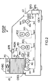
- La Fig.2 est une vue en coupe schématique de ce dispositif dans une configuration particulière,
- La Fig.3 est une vue en coupe d'un chargeur vide conforme à une variante de l'invention, et
- La Fig.4 est une vue en coupe d'un chargeur plein conforme à cette variante de l'invention.
- La Fig.1 représente de façon schématique un dispositif de traitement DISP d'au moins une surface d'un objet OBJ1 ou OBJ2, présentant une première et une deuxième entrée E1 et E2 pour recevoir respectivement des objets OBJ1 en provenance d'un chargeur CHRG destiné à contenir une pluralité de tels objets, et des objets OBJ2 fournis individuellement par un utilisateur du dispositif.
- Ce dispositif DISP inclut une unique chaîne opératoire présentant une entrée destinée à recevoir des objets OBJ1 ou OBJ2 depuis l'une ou l'autre des première et deuxième entrées E1 et E2 du dispositif, laquelle chaîne opératoire inclut deux postes opératoires successifs PO1 et PO2, chacun apte à exercer une action sur au moins une surface dudit objet. Dans cet exemple, le premier poste opératoire PO1 est destiné à réaliser, au moyen d'une tête magnétique TM, un encodage d'une bande magnétique disposée sur une surface inférieure des objets à traiter. Le deuxième poste opératoire P02 est destiné à réaliser, au moyen d'une tête d'impression TI, une impression d'une surface supérieure des objets à traiter.
- Dans ce mode de réalisation particulier de l'invention, les actions, encodage ou impression, que les postes opératoires PO1 et PO2 sont aptes à exercer peuvent être préalablement inhibées ou au contraire autorisées par programmation. Le dispositif DISP présente à cet effet un panneau de commande muni d'une touche BPO, sur laquelle un utilisateur du dispositif DISP peut agir pour sélectionner les postes opératoires dont il souhaitera inhiber ou autoriser les actions. Des actions sur cette touche BPO seront perçues par un module de contrôle OCM, qui les traduira en signaux électriques Spo1 et Spo2 présentant des états ou valeurs qui seront représentatifs du choix de l'utilisateur, et commanderont l'inhibition ou l'autorisation de fonctionnement des postes opératoires PO1 et PO2. A l'issue d'une initialisation du dispositif DISP, les signaux Spo1 et Spo2 pourront par exemple se voir attribuer tous deux par défaut une valeur autorisant le fonctionnement des postes opératoires PO1 et PO2, une pression unique sur la touche BPO commandant l'inhibition de l'un desdits postes PO1 ou PO2, alors que deux pressions successives commanderont l'inhibition de l'autre poste PO2 ou PO1. Ce mode de réalisation permet ainsi de configurer de manière flexible la chaîne opératoire en fonction de la nature du ou des traitements de surface à réaliser et, une fois la configuration souhaitée programmée, de traiter en série des objets, par exemple depuis le chargeur CHRG, ce qui permet de réduire le prix de revient du traitement appliqué à chaque objet en augmentant la cadence de traitement par rapport au dispositif connu, pour lequel au moins une manipulation de chaque objet entre deux postes opératoires distincts est inévitable.
- Dans ce mode de réalisation particulier de l'invention, les première et deuxième entrées E1 et E2 du dispositif DISP sont situées de part et d'autre de la chaîne opératoire, le dispositif DISP étant muni de moyens d'acheminement pour acheminer vers l'entrée de la chaîne opératoire un objet OBJ2 introduit dans le dispositif DISP par sa deuxième entrée E2.
- Un tel agencement des première et deuxième entrées E1 et E2 est avantageux en termes d'ergonomie, puisqu'il permet d'éviter toute confusion dans l'esprit d'un utilisateur du dispositif DISP quant aux positions respectives des première et deuxième entrées E1 et E2, qui sont ici disposées aussi loin que possible l'une de l'autre. Ceci permet donc de simplifier l'approvisionnement du dispositif DISP en objets individuels OBJ2 au travers de la deuxième entrée E2, ce qui permet de réduire encore le prix de revient du traitement réalisé par ce dispositif DISP.
- Par ailleurs, cette autre variante de l'invention rend possible l'acheminement vers l'entrée de la chaîne opératoire d'un objet OBJ2 introduit au travers de la deuxième entrée E2 du dispositif DISP au moyen d'une translation, ce qui facilitera l'acheminement d'objets rigides ou peu flexibles.
- La chaîne opératoire est munie de moyens d'entraînement, constitués dans cet exemple par des rouleaux RE1, RE2, RE3 et RE4 aptes à être entraînés en rotation dans le but de déplacer les objets depuis l'entrée de ladite chaîne opératoire vers une sortie, laquelle sortie est dans cet exemple située en vis-à-vis de la deuxième entrée E2 du dispositif DISP. Les moyens d'entraînement RE1, RE2, RE3 et RE4 sont aptes à être configurés, sur ordre d'un utilisateur du dispositif DISP, dans un mode de fonctionnement inverse dans lequel le sens de rotation des rouleaux est inversé afin de permettre un acheminement d'objets depuis la deuxième entrée E2 vers l'entrée de la chaîne opératoire. Les moyens d'acheminement seront ainsi constitués par des ressources préexistantes, en l'occurrence les moyens d'entraînement configurés en mode de fonctionnement inverse. Cette configuration est réalisée dans cet exemple au moyen de signaux électriques Sr1, Spo1, Spo2 et Sr4, respectivement, lesquels signaux seront générés par le module de contrôle OCM commandé par l'utilisateur au moyen d'une touche de commande BPS. On pourra en outre munir le dispositif DISP d'un détecteur d'insertion DET d'un objet OBJ2 au travers de la deuxième entrée, par exemple un capteur photoélectrique, qui pourra provoquer automatiquement une configuration des moyens d'entraînement RE1, RE2, RE3 et RE4 en mode de fonctionnement inverse via le module de contrôle OCM et les signaux électriques Sr1, Spo1, Spo2 et Sr4 dès qu'une telle insertion aura été détectée par le détecteur d'insertion DET et signalée au module de contrôle OCM par une activation d'un signal de détection Sd, laquelle activation pourra par exemple être matérialisée par un passage d'un niveau logique "0" à un niveau logique "1" dudit signal de détection Sd.
- Deux rouleaux de nettoyage RN1 et RN2, disposés respectivement en vis-à-vis des première et deuxième entrées E1 et E2, permettent en outre d'assurer que les objets à traiter sont exempts de poussière ou d'autres impuretés avant leur traitement par la chaîne opératoire, et ce quelle que soit l'entrée E1 ou E2 au travers de laquelle ils auront été insérés.
- Dans ce mode de mise en oeuvre particulier de l'invention, le chargeur CHRG est muni d'une première paroi P1 destinée à empêcher un mouvement selon une première direction d1 des objets OBJ1 contenus dans le chargeur CHRG, et d'une deuxième paroi P2 destinée à empêcher un mouvement desdits objets OBJ1 selon une deuxième direction d2 perpendiculaire à la première direction d1, dans un sens opposé à celui attribué à la deuxième direction d2 dans cet exemple. Les première et deuxième parois P1 et P2 présentent des extrémités qui sont séparées par une ouverture destinée à être traversée par un objet OBJ1. Le chargeur CHRG inclut un coulisseau CLS apte à se déplacer le long de la deuxième paroi P2 dans la première direction d1 sous l'effet d'une force produite par un élément élastique, par exemple un ressort RS, les objets OBJ1 contenus dans le chargeur CHRG étant destinés à être disposés entre ledit coulisseau CLS et la première paroi P1. Dans l'exemple décrit ici, la deuxième paroi P2 du chargeur CHRG est mobile dans la direction d1 et le dispositif de traitement DISP est muni de moyens de déplacement, qui incluent un élément cylindrique RG apte à être entraîné en rotation autour d'un axe perpendiculaire aux première et deuxième directions d1 et d2 sur commande d'un signal électrique Srg généré par un module de réglage RGM en réponse à une commande exercée par un utilisateur du dispositif DISP sur une touche de réglage BPR, afin de piloter un déplacement de ladite deuxième paroi P2 et de réaliser ainsi un réglage de la taille de ladite ouverture.
- Ce mode de réalisation du chargeur CHRG et du dispositif DISP est avantageux en ce qu'il autorise un traitement en série d'objets OBJ1 pouvant présenter des épaisseurs variables, puisque la taille de l'ouverture du chargeur CHRG, au travers de laquelle lesdits objets OBJ1 sont acheminés vers l'entrée de la chaîne opératoire, est réglable.
- Dans cet exemple de réalisation particulier du chargeur CHRG, la deuxième paroi P2 est mobile d'un seul tenant, mais on pourra prévoir, dans d'autres modes de réalisation, que seule une portion de cette deuxième paroi P2, localisée au niveau de l'ouverture, soit mobile aux fins de réglage de la taille de ladite ouverture.
- L'avantage technique apporté par la mobilité, totale ou partielle, de la deuxième paroi P2 conservera tout son intérêt dans d'autres applications que celle décrite ici, en particulier dans le cadre d'une utilisation où le dispositif de traitement ne présenterait qu'une seule entrée destinée à recevoir les objets stockés dans le chargeur.
- La Fig.2 représente de façon schématique ce dispositif DISP dans une configuration particulière. En effet, dans ce mode de mise en oeuvre particulier de l'invention, le dispositif de traitement DISP inclut en outre des moyens d'écartement destinés à déplacer dans la première direction d1 celui des objets OBJ1 contenus dans le chargeur CHRG qui est le plus proche de la première paroi P1 afin de l'écarter de ladite première paroi P1 pour ménager entre ledit objet et ladite première paroi P1 un espace de stockage apte à recevoir au moins partiellement un objet en provenance de la chaîne opératoire. Dans l'exemple de réalisation décrit ici, les moyens d'écartement incluent une came CM apte à pivoter autour d'un axe perpendiculaire aux première et deuxième directions d1 et d2, sur commande d'un signal électrique Scm généré par le module de contrôle OCM. Dans cette configuration, la rotation de la came CM provoque un soulèvement des objets OBJ1 inclus dans le chargeur CHRG, ce qui libère au sein dudit chargeur un espace de stockage dans lequel un autre objet, dans cet exemple un objet OBJ2 provenant de la deuxième entrée E2, peut être inséré et maintenu en attente de son traitement par la chaîne opératoire, sans nécessiter la création d'un espace supplémentaire à cet effet, ce qui permet de réduire encore l'encombrement total du dispositif de traitement DISP. Dans un mode de réalisation particulier des moyens d'écartement, on pourra prévoir qu'un actionnement desdits moyens provoquera simultanément une inhibition momentanée, par exemple par débrayage de leurs rouleaux d'entraînement, des postes opératoires PO1 et PO2, afin de garantir leur inactivité lorsque l'objet à traiter est en position d'attente.
- Les Fig.3 et 4 représentent un chargeur CHRG conforme à un autre aspect de l'invention, dans des états respectivement vide et plein. Ainsi qu'exposé précédemment, ce chargeur CHRG est muni d'une première paroi P1 destinée à empêcher un mouvement selon une première direction d1 d'objets contenus dans le chargeur, et d'une deuxième paroi P2 destinée à empêcher un mouvement desdits objets selon une deuxième direction d2 perpendiculaire à la première direction d1, dans un sens opposé à celui attribué à la deuxième direction d2 dans cet exemple, les première et deuxième parois P1 et P2 présentant des extrémités qui sont séparées par une ouverture OUV destinée à être traversée par un objet OBJ. Le chargeur CHRG inclut un coulisseau CLS apte à se déplacer le long de la deuxième paroi P2 dans la première direction d1 sous l'effet d'une force produite par un ressort RS, les objets contenus dans le chargeur CHRG étant destinés à être disposés entre ledit coulisseau CLS et la première paroi P1. Les objets peuvent d'une manière générale présenter diverses formes. Dans l'exemple décrit ici, ces objets pourront être constitués par des cartes en matière plastique conformes au format ISO CR80. Selon cet aspect de l'invention, le chargeur CHRG inclut en outre des moyens de régulation destinés à maintenir sensiblement constante la force exercée sur celui des objets OBJ contenus dans le chargeur qui est le plus proche de la première paroi P1.
- Cet aspect de l'invention est avantageux en ce qu'il permet une extraction dans des conditions homogènes des objets depuis le chargeur CHRG. En effet, grâce aux moyens de régulation, un objet OBJ directement en contact avec le coulisseau CLS ou un objet séparé dudit coulisseau par une pile d'autres objets seront soumis à une pression sensiblement identique, bien que le ressort RS soit plus comprimé en présence d'une pile d'objets qu'en présence d'un seul objet, et qu'un objet OBJ placé en dessous d'une pile de tels objets soit soumis de surcroît à une force de pesanteur exercée par ladite pile. Ceci permet de connaître précisément les conditions dans lesquelles des moyens d'extraction, par exemple un rouleau avec lequel l'objet OBJ destiné à être extrait du chargeur CHRG sera en contact, seront amenés à fonctionner en toutes circonstances, et de concevoir et de dimensionner lesdits moyens d'extraction de façon optimale pour en assurer un fonctionnement efficace, que le chargeur CHRG soit plein ou presque vide.
- Dans ce mode de mise en oeuvre de l'invention, les moyens de régulation incluent un ressort RS, par exemple un ressort cylindrique autour d'un axe de révolution disposé parallèlement à la deuxième direction d2, relié à une première et une deuxième articulation A1 et A2, dans cet exemple des liaisons pivot, entre des première et deuxième tiges T1 et T2, d'une part, et des troisième et quatrième tiges T3 et T4, d'autre part. Des extrémités E1 et E2 des première et deuxième tiges T1 et T2 sont reliées par des liaisons pivot glissant à des glissières G1 et G2 respectivement aménagées dans le chargeur CHRG et le coulisseau CLS. Des extrémités PF1 et PF2 des troisième et quatrième tiges T3 et T4 sont reliées par des liaisons pivot à des points fixes aménagés dans le chargeur CHRG et le coulisseau CLS.
- Les liaisons glissière liant respectivement les extrémités E1 et E2 au chargeur CHRG et au coulisseau CLS permettent d'augmenter un angle que présentent les tiges T1, T2, T3, T4 avec la deuxième direction d2, qui est en principe la direction horizontale, au fur et à mesure que le chargeur CHRG sera vidé des objets qu'il aura initialement contenu. Par ailleurs, la force exercée par le ressort RS selon la première direction d1 sur ces objets est proportionnelle au sinus dudit angle, ce qui implique que cette force augmente à mesure que la valeur dudit angle augmente. D'autre part, la force de pesanteur exercée par la pile de cartes placée au-dessus de l'objet OBJ qui est le plus proche de la première paroi P1 du chargeur CHRG diminuera à mesure que le chargeur CHRG sera vidé des objets qu'il contient. Ceci a pour conséquence que l'accroissement de la force exercée selon la première direction d1 sur l'objet OBJ par le ressort RS, qui est provoqué par la diminution du nombre de cartes dans le chargeur CHRG et l'accroissement consécutif de l'angle entre les tiges T1, T2, T3 et T4 et la deuxième direction d2, sera compensé par la diminution de la force de pesanteur exercée par la pile d'objets situés au-dessus dudit objet OBJ à mesure que le nombre d'objets formant ladite pile diminue, avec pour effet de maintenir sensiblement constante la résultante selon la première direction d1 desdites forces.
Claims (6)
- Dispositif de traitement d'au moins une surface d'un objet (OBJ1, OBJ2), présentant une première entrée (E1) pour recevoir des objets en provenance d'un chargeur (CHRG) destiné à contenir une pluralité de tels objets, une deuxième entrée (E2), distincte de la première entrée (E1), pour recevoir des objets fournis individuellement par un utilisateur du dispositif, et incluant au moins une chaîne opératoire présentant une entrée destinée à recevoir des objets (OBJ1) depuis la première (E1) et la deuxième (E2) entrées du dispositif, chaque chaîne opératoire incluant au moins un poste opératoire (PO1, PO2) apte à exercer une action sur une surface dudit objet, la chaîne opératoire étant munie de moyens d'entraînement permettant de déplacer les objets depuis son entrée vers une sortie de ladite chaîne opératoire, dispositif caractérisé en ce que les première (E1) et deuxième (E2) entrées du dispositif sont situées de part et d'autre de la chaîne opératoire, et en ce que lesdits moyens d'entraînement sont aptes à être configurés dans un mode de fonctionnement inverse dans lequel ils permettent de déplacer les objets depuis la sortie vers l'entrée de la chaîne opératoire, la deuxième entrée (E2) du dispositif étant disposée en vis-à-vis de ladite sortie de la chaîne opératoire.
- Dispositif de traitement selon la revendication 1, caractérisé en ce qu'il inclut une unique chaîne opératoire incluant une succession de postes opératoires.
- Dispositif de traitement selon la revendication 1 ou 2, caractérisé en ce que l'action qu'au moins un poste opératoire est apte à exercer peut être préalablement inhibée ou autorisée par programmation.
- Dispositif de traitement selon l'une des revendications 1 à 3, caractérisé en ce que, le chargeur (CHRG) étant muni d'une première paroi (P1) destinée à empêcher un mouvement selon une première direction (d1) des objets (OBJ1) contenus dans le chargeur, et d'une deuxième paroi (P2) destinée à empêcher un mouvement desdits objets (OBJ2) selon une deuxième direction perpendiculaire à la première direction (d1), les première (P1) et deuxième (P2) parois présentant des extrémités qui sont séparées par une ouverture destinée à être traversée par un objet (OBJ1), e chargeur (CHRG) inclut un coulisseau (CLS) apte à se déplacer le long de la deuxième paroi (P2) dans la première direction (d1) sous l'effet d'une force produite par un élément élastique, les objets (OBJ1) contenus dans le chargeur (CHRG) étant destinés à être disposés entre ledit coulisseau (CLS) et la première paroi (P1), le chargeur (CHRG) inclut en outre des moyens de régulation incluant un ressort (RS) disposé parallèlement à la deuxième direction et relié à une première et une deuxième articulation (A1,A2) respectivement aménagées entre des première et deuxième tiges (T1,T2), d'une part, et des troisième et quatrième tiges (T3,T4), d'autre part, des extrémités des première et deuxième tiges (T1,T2) étant reliées par des liaisons pivot à des première et deuxième glissières (G1, G2) respectivement aménagées dans le chargeur (CHRG) et le coulisseau (CLS), des extrémités des troisième et quatrième tiges (T3, T4) étant reliées par des liaisons pivot à des points fixes respectivement aménagés dans le chargeur (CHRG) et le coulisseau (CLS), lesdits moyens de régulation étant aussi destinés à maintenir sensiblement constante la force exercée sur celui des objets (OBJ1) contenus dans le chargeur (CHRG) qui est le plus proche de la première paroi (P1).
- Dispositif de traitement selon la revendication 4, caractérisé en ce qu'au moins une partie de ladite deuxième paroi du chargeur est mobile, le dispositif de traitement étant muni de moyens de déplacement pour piloter un déplacement de ladite partie mobile de la deuxième paroi autorisant un réglage de la taille de ladite ouverture.
- Dispositif de traitement selon la revendication 4 ou 5, caractérisé en ce que le dispositif inclut en outre des moyens d'écartement destinés à déplacer dans la première direction celui des objets contenus dans le chargeur qui est le plus proche de la première paroi afin de l'écarter de ladite première paroi pour ménager entre ledit objet et ladite première paroi un espace apte à recevoir au moins partiellement un objet en provenance de la chaîne opératoire.
Priority Applications (1)
| Application Number | Priority Date | Filing Date | Title |
|---|---|---|---|
| AT02720059T ATE342171T1 (de) | 2002-03-12 | 2002-03-12 | Gerät mit reduzierten abmessungen und verbesserter ergonomie zur behandlung der oberfläche von objekten |
Applications Claiming Priority (1)
| Application Number | Priority Date | Filing Date | Title |
|---|---|---|---|
| PCT/FR2002/000883 WO2003076200A1 (fr) | 2002-03-12 | 2002-03-12 | Dispositif de traitement de surface d'objets a encombrement reduit et ergonomie amelioree |
Publications (2)
| Publication Number | Publication Date |
|---|---|
| EP1483120A1 EP1483120A1 (fr) | 2004-12-08 |
| EP1483120B1 true EP1483120B1 (fr) | 2006-10-11 |
Family
ID=27799040
Family Applications (1)
| Application Number | Title | Priority Date | Filing Date |
|---|---|---|---|
| EP02720059A Expired - Lifetime EP1483120B1 (fr) | 2002-03-12 | 2002-03-12 | Dispositif de traitement de surface d'objets a encombrement reduit et ergonomie amelioree |
Country Status (5)
| Country | Link |
|---|---|
| US (1) | US7621520B2 (fr) |
| EP (1) | EP1483120B1 (fr) |
| AU (1) | AU2002251132A1 (fr) |
| DE (1) | DE60215392T2 (fr) |
| WO (1) | WO2003076200A1 (fr) |
Families Citing this family (11)
| Publication number | Priority date | Publication date | Assignee | Title |
|---|---|---|---|---|
| US9676179B2 (en) * | 2005-04-20 | 2017-06-13 | Zih Corp. | Apparatus for reducing flash for thermal transfer printers |
| CN101180186B (zh) | 2005-04-20 | 2010-09-15 | Zih公司 | 单次通过双面图像转印处理和系统 |
| US7665920B2 (en) * | 2007-03-08 | 2010-02-23 | Fargo Electronics, Inc. | Card holder for a credential production device |
| US8721205B2 (en) * | 2007-10-10 | 2014-05-13 | Hid Global Corporation | Credential manufacturing device having an auxiliary card input |
| FR2948110B1 (fr) * | 2009-07-16 | 2011-07-29 | Evolis | Machine de traitement destinee a traiter une serie de cartes |
| CN102497991B (zh) | 2009-09-18 | 2014-07-30 | Hid环球公司 | 证件处理装置中的证件基片进给装置和方法 |
| ES2565477T3 (es) | 2009-09-18 | 2016-04-05 | Assa Abloy Ab | Conjunto de tolva doble |
| FR2973282B1 (fr) * | 2011-04-04 | 2016-12-09 | Evolis | Imprimante et chargeur de cartes pour imprimante |
| DE202011107379U1 (de) * | 2011-10-31 | 2011-11-15 | Francotyp-Postalia Gmbh | Modulare Anlegevorrichtung einer Zuführstation |
| ITUA20163368A1 (it) * | 2016-05-12 | 2017-11-12 | Marchesini Group Spa | Dispositivo di stabilizzazione per stabilizzare articoli durante il loro sollevamento e raggruppamento |
| US10377591B2 (en) | 2017-07-07 | 2019-08-13 | Zebra Technologies Corporation | Input handling for media processing devices |
Family Cites Families (8)
| Publication number | Priority date | Publication date | Assignee | Title |
|---|---|---|---|---|
| US4021032A (en) * | 1976-03-12 | 1977-05-03 | Computer Terminal Systems, Inc. | Feeding device |
| WO1985001820A1 (fr) * | 1983-10-11 | 1985-04-25 | Matsushita Electric Industrial Co.,Ltd. | Appareil recevant et rendant des billets de banque |
| DE8630748U1 (de) * | 1986-11-14 | 1987-02-19 | Francotyp-Postalia Gmbh, 13409 Berlin | Kassette mit Streifenbox für Streifengeber von Postbearbeitungsmaschinen |
| DE3704059A1 (de) * | 1987-02-10 | 1988-08-18 | Base Ten Systems Electronics G | Vorrichtung fuer das aufbringen von informationen auf blattfoermige datentraeger, wie karteikarten oder dergleichen |
| US5177547A (en) * | 1989-04-26 | 1993-01-05 | Canon Kabushiki Kaisha | Recording apparatus which uses the sheet ejection outlet as a sheet insertion inlet |
| US5177347A (en) * | 1991-09-19 | 1993-01-05 | Ncr Corporation | Axially invariant pattern scanning apparatus |
| JP3309943B2 (ja) | 1995-11-13 | 2002-07-29 | ニスカ株式会社 | 記録装置 |
| US7182330B2 (en) * | 2002-12-09 | 2007-02-27 | Smead Manufacturing Company | Intelligent autonomous sheet feeder for the infeed of a printer |
-
2002
- 2002-03-12 US US10/507,244 patent/US7621520B2/en not_active Expired - Lifetime
- 2002-03-12 DE DE60215392T patent/DE60215392T2/de not_active Expired - Lifetime
- 2002-03-12 AU AU2002251132A patent/AU2002251132A1/en not_active Abandoned
- 2002-03-12 EP EP02720059A patent/EP1483120B1/fr not_active Expired - Lifetime
- 2002-03-12 WO PCT/FR2002/000883 patent/WO2003076200A1/fr not_active Ceased
Also Published As
| Publication number | Publication date |
|---|---|
| EP1483120A1 (fr) | 2004-12-08 |
| US7621520B2 (en) | 2009-11-24 |
| WO2003076200B1 (fr) | 2004-05-27 |
| AU2002251132A1 (en) | 2003-09-22 |
| WO2003076200A1 (fr) | 2003-09-18 |
| US20060151935A1 (en) | 2006-07-13 |
| DE60215392T2 (de) | 2007-08-23 |
| DE60215392D1 (de) | 2006-11-23 |
Similar Documents
| Publication | Publication Date | Title |
|---|---|---|
| EP0677393B1 (fr) | Système d'impression automatique recto verso de cartes en noir et blanc et en couleurs par retournement de la carte | |
| EP1483120A1 (fr) | Dispositif de traitement de surface d'objets a encombrement reduit et ergonomie amelioree | |
| FR2621305A1 (fr) | Appareil de manipulation de feuilles | |
| EP0589755A1 (fr) | Terminal de jeux | |
| EP3201714B1 (fr) | Procede de fabrication d'un dispositif et d'un systeme comprenant ce dispositif, tel qu'une carte avec ecran, et systeme de personnalisation d'un support traditionnel integrant un afficheur video et photo | |
| FR2481958A1 (fr) | Trieuse a plateaux mobiles pour copieur | |
| FR2609009A1 (fr) | Machine de reception et de distribution de billets | |
| EP4121918A1 (fr) | Colis comprenant un capteur d'images d'un objet à l'intérieur du colis, et un écran d'affichage externe des images prises par le capteur | |
| RU2608271C2 (ru) | Устройство обращения с носителями и устройство обработки носителей | |
| FR2678594A1 (fr) | Machine de reception et de distribution de billets. | |
| FR2669267A1 (fr) | Machine de personnalisation pour cartes a puces. | |
| EP1296778B1 (fr) | Poste de video-codage pour installation de tri automatique d'objets postaux | |
| EP0025390B1 (fr) | Magasin débiteur de films destiné à équiper un changeur de films radiographiques, et changeur équipé d'un tel magasin | |
| CH677340A5 (fr) | ||
| FR2773547A1 (fr) | Dispositif de traitement de feuilles | |
| WO2016030637A2 (fr) | Coque pour système de télécommunication portable | |
| CH682775A5 (fr) | Lecteur de carte. | |
| EP4303837A1 (fr) | Dispositif de capture d'empreinte biométrique sans contact | |
| FR3074312A1 (fr) | Dispositif de controle d'acces d'un individu par reconnaissance 2d ou 3d du visage d'un individu a partir de son acquisition prealable 3d | |
| EP0855683A1 (fr) | Machine compacte de traitement de courrier à chemin de transport particulier | |
| FR2776279A1 (fr) | Dispositif de traitement de feuilles comprenant deux chemins de transfert de telles feuilles | |
| FR2977058A1 (fr) | Distributeur automatique de repas et procede de fonctionnement | |
| FR2827263A1 (fr) | Dispositif permettant de deramer des cartes rigides ou relativement rigides empilees les unes sur les autres | |
| KR102152899B1 (ko) | 금융 자동화 기기 | |
| FR2827488A1 (fr) | Etui pour carte bancaire ou analogue |
Legal Events
| Date | Code | Title | Description |
|---|---|---|---|
| PUAI | Public reference made under article 153(3) epc to a published international application that has entered the european phase |
Free format text: ORIGINAL CODE: 0009012 |
|
| AK | Designated contracting states |
Kind code of ref document: A1 Designated state(s): AT BE CH CY DE DK ES FI FR GB GR IE IT LI LU MC NL PT SE TR |
|
| AX | Request for extension of the european patent |
Extension state: AL LT LV MK RO SI |
|
| 17P | Request for examination filed |
Effective date: 20040823 |
|
| RIN1 | Information on inventor provided before grant (corrected) |
Inventor name: LIATARD, YVES Inventor name: GODARD, DIDIER |
|
| GRAP | Despatch of communication of intention to grant a patent |
Free format text: ORIGINAL CODE: EPIDOSNIGR1 |
|
| GRAS | Grant fee paid |
Free format text: ORIGINAL CODE: EPIDOSNIGR3 |
|
| GRAA | (expected) grant |
Free format text: ORIGINAL CODE: 0009210 |
|
| AK | Designated contracting states |
Kind code of ref document: B1 Designated state(s): AT BE CH CY DE DK ES FI FR GB GR IE IT LI LU MC NL PT SE TR |
|
| PG25 | Lapsed in a contracting state [announced via postgrant information from national office to epo] |
Ref country code: IE Free format text: LAPSE BECAUSE OF FAILURE TO SUBMIT A TRANSLATION OF THE DESCRIPTION OR TO PAY THE FEE WITHIN THE PRESCRIBED TIME-LIMIT Effective date: 20061011 Ref country code: FI Free format text: LAPSE BECAUSE OF FAILURE TO SUBMIT A TRANSLATION OF THE DESCRIPTION OR TO PAY THE FEE WITHIN THE PRESCRIBED TIME-LIMIT Effective date: 20061011 Ref country code: NL Free format text: LAPSE BECAUSE OF FAILURE TO SUBMIT A TRANSLATION OF THE DESCRIPTION OR TO PAY THE FEE WITHIN THE PRESCRIBED TIME-LIMIT Effective date: 20061011 Ref country code: AT Free format text: LAPSE BECAUSE OF FAILURE TO SUBMIT A TRANSLATION OF THE DESCRIPTION OR TO PAY THE FEE WITHIN THE PRESCRIBED TIME-LIMIT Effective date: 20061011 |
|
| REG | Reference to a national code |
Ref country code: GB Ref legal event code: FG4D Free format text: NOT ENGLISH |
|
| REG | Reference to a national code |
Ref country code: CH Ref legal event code: EP |
|
| REG | Reference to a national code |
Ref country code: IE Ref legal event code: FG4D Free format text: LANGUAGE OF EP DOCUMENT: FRENCH |
|
| REF | Corresponds to: |
Ref document number: 60215392 Country of ref document: DE Date of ref document: 20061123 Kind code of ref document: P |
|
| GBT | Gb: translation of ep patent filed (gb section 77(6)(a)/1977) |
Effective date: 20061123 |
|
| PG25 | Lapsed in a contracting state [announced via postgrant information from national office to epo] |
Ref country code: DK Free format text: LAPSE BECAUSE OF FAILURE TO SUBMIT A TRANSLATION OF THE DESCRIPTION OR TO PAY THE FEE WITHIN THE PRESCRIBED TIME-LIMIT Effective date: 20070111 Ref country code: SE Free format text: LAPSE BECAUSE OF FAILURE TO SUBMIT A TRANSLATION OF THE DESCRIPTION OR TO PAY THE FEE WITHIN THE PRESCRIBED TIME-LIMIT Effective date: 20070111 |
|
| PG25 | Lapsed in a contracting state [announced via postgrant information from national office to epo] |
Ref country code: ES Free format text: LAPSE BECAUSE OF FAILURE TO SUBMIT A TRANSLATION OF THE DESCRIPTION OR TO PAY THE FEE WITHIN THE PRESCRIBED TIME-LIMIT Effective date: 20070122 |
|
| PG25 | Lapsed in a contracting state [announced via postgrant information from national office to epo] |
Ref country code: PT Free format text: LAPSE BECAUSE OF FAILURE TO SUBMIT A TRANSLATION OF THE DESCRIPTION OR TO PAY THE FEE WITHIN THE PRESCRIBED TIME-LIMIT Effective date: 20070319 |
|
| NLV1 | Nl: lapsed or annulled due to failure to fulfill the requirements of art. 29p and 29m of the patents act | ||
| REG | Reference to a national code |
Ref country code: IE Ref legal event code: FD4D |
|
| PLBE | No opposition filed within time limit |
Free format text: ORIGINAL CODE: 0009261 |
|
| STAA | Information on the status of an ep patent application or granted ep patent |
Free format text: STATUS: NO OPPOSITION FILED WITHIN TIME LIMIT |
|
| 26N | No opposition filed |
Effective date: 20070712 |
|
| REG | Reference to a national code |
Ref country code: CH Ref legal event code: PL |
|
| BERE | Be: lapsed |
Owner name: EVOLIS CARD PRINTER SA Effective date: 20070331 |
|
| PG25 | Lapsed in a contracting state [announced via postgrant information from national office to epo] |
Ref country code: BE Free format text: LAPSE BECAUSE OF NON-PAYMENT OF DUE FEES Effective date: 20070331 |
|
| PG25 | Lapsed in a contracting state [announced via postgrant information from national office to epo] |
Ref country code: MC Free format text: LAPSE BECAUSE OF NON-PAYMENT OF DUE FEES Effective date: 20070331 |
|
| PG25 | Lapsed in a contracting state [announced via postgrant information from national office to epo] |
Ref country code: LI Free format text: LAPSE BECAUSE OF NON-PAYMENT OF DUE FEES Effective date: 20070331 Ref country code: CH Free format text: LAPSE BECAUSE OF NON-PAYMENT OF DUE FEES Effective date: 20070331 |
|
| PG25 | Lapsed in a contracting state [announced via postgrant information from national office to epo] |
Ref country code: GR Free format text: LAPSE BECAUSE OF FAILURE TO SUBMIT A TRANSLATION OF THE DESCRIPTION OR TO PAY THE FEE WITHIN THE PRESCRIBED TIME-LIMIT Effective date: 20070112 |
|
| REG | Reference to a national code |
Ref country code: FR Ref legal event code: RM Ref country code: FR Ref legal event code: CA |
|
| REG | Reference to a national code |
Ref country code: GB Ref legal event code: S117 Free format text: REQUEST FILED; REQUEST FOR CORRECTION UNDER SECTION 117 FILED ON 22 APRIL 2009 |
|
| PG25 | Lapsed in a contracting state [announced via postgrant information from national office to epo] |
Ref country code: LU Free format text: LAPSE BECAUSE OF NON-PAYMENT OF DUE FEES Effective date: 20070312 Ref country code: CY Free format text: LAPSE BECAUSE OF FAILURE TO SUBMIT A TRANSLATION OF THE DESCRIPTION OR TO PAY THE FEE WITHIN THE PRESCRIBED TIME-LIMIT Effective date: 20061011 |
|
| PG25 | Lapsed in a contracting state [announced via postgrant information from national office to epo] |
Ref country code: TR Free format text: LAPSE BECAUSE OF FAILURE TO SUBMIT A TRANSLATION OF THE DESCRIPTION OR TO PAY THE FEE WITHIN THE PRESCRIBED TIME-LIMIT Effective date: 20061011 |
|
| REG | Reference to a national code |
Ref country code: GB Ref legal event code: S117 Free format text: CORRECTIONS ALLOWED; REQUEST FOR CORRECTION UNDER SECTION 117 FILED ON 22 APRIL 2009 ALLOWED ON 16 SEPTEMBER 2009 |
|
| REG | Reference to a national code |
Ref country code: DE Ref legal event code: R082 Ref document number: 60215392 Country of ref document: DE Representative=s name: PATENTANWAELTE WEICKMANN & WEICKMANN, DE Ref country code: DE Ref legal event code: R082 Ref document number: 60215392 Country of ref document: DE Representative=s name: WEICKMANN & WEICKMANN PATENTANWAELTE - RECHTSA, DE Ref country code: DE Ref legal event code: R082 Ref document number: 60215392 Country of ref document: DE Representative=s name: WEICKMANN & WEICKMANN PATENT- UND RECHTSANWAEL, DE |
|
| REG | Reference to a national code |
Ref country code: FR Ref legal event code: PLFP Year of fee payment: 15 |
|
| REG | Reference to a national code |
Ref country code: FR Ref legal event code: PLFP Year of fee payment: 16 |
|
| REG | Reference to a national code |
Ref country code: FR Ref legal event code: PLFP Year of fee payment: 17 |
|
| PGFP | Annual fee paid to national office [announced via postgrant information from national office to epo] |
Ref country code: FR Payment date: 20210326 Year of fee payment: 20 |
|
| PGFP | Annual fee paid to national office [announced via postgrant information from national office to epo] |
Ref country code: DE Payment date: 20210420 Year of fee payment: 20 Ref country code: IT Payment date: 20210427 Year of fee payment: 20 |
|
| PGFP | Annual fee paid to national office [announced via postgrant information from national office to epo] |
Ref country code: GB Payment date: 20210421 Year of fee payment: 20 |
|
| REG | Reference to a national code |
Ref country code: DE Ref legal event code: R071 Ref document number: 60215392 Country of ref document: DE |
|
| REG | Reference to a national code |
Ref country code: GB Ref legal event code: PE20 Expiry date: 20220311 |
|
| PG25 | Lapsed in a contracting state [announced via postgrant information from national office to epo] |
Ref country code: GB Free format text: LAPSE BECAUSE OF EXPIRATION OF PROTECTION Effective date: 20220311 |