EP1482866B1 - Dispositif permettant la mise en place d'un dispositif endoluminal - Google Patents
Dispositif permettant la mise en place d'un dispositif endoluminal Download PDFInfo
- Publication number
- EP1482866B1 EP1482866B1 EP03711107A EP03711107A EP1482866B1 EP 1482866 B1 EP1482866 B1 EP 1482866B1 EP 03711107 A EP03711107 A EP 03711107A EP 03711107 A EP03711107 A EP 03711107A EP 1482866 B1 EP1482866 B1 EP 1482866B1
- Authority
- EP
- European Patent Office
- Prior art keywords
- sheath
- introducer
- retrograde
- anterograde
- endoluminal device
- Prior art date
- Legal status (The legal status is an assumption and is not a legal conclusion. Google has not performed a legal analysis and makes no representation as to the accuracy of the status listed.)
- Expired - Lifetime
Links
Images


Classifications
-
- A—HUMAN NECESSITIES
- A61—MEDICAL OR VETERINARY SCIENCE; HYGIENE
- A61F—FILTERS IMPLANTABLE INTO BLOOD VESSELS; PROSTHESES; DEVICES PROVIDING PATENCY TO, OR PREVENTING COLLAPSING OF, TUBULAR STRUCTURES OF THE BODY, e.g. STENTS; ORTHOPAEDIC, NURSING OR CONTRACEPTIVE DEVICES; FOMENTATION; TREATMENT OR PROTECTION OF EYES OR EARS; BANDAGES, DRESSINGS OR ABSORBENT PADS; FIRST-AID KITS
- A61F2/00—Filters implantable into blood vessels; Prostheses, i.e. artificial substitutes or replacements for parts of the body; Appliances for connecting them with the body; Devices providing patency to, or preventing collapsing of, tubular structures of the body, e.g. stents
- A61F2/95—Instruments specially adapted for placement or removal of stents or stent-grafts
- A61F2/962—Instruments specially adapted for placement or removal of stents or stent-grafts having an outer sleeve
- A61F2/966—Instruments specially adapted for placement or removal of stents or stent-grafts having an outer sleeve with relative longitudinal movement between outer sleeve and prosthesis, e.g. using a push rod
-
- A—HUMAN NECESSITIES
- A61—MEDICAL OR VETERINARY SCIENCE; HYGIENE
- A61F—FILTERS IMPLANTABLE INTO BLOOD VESSELS; PROSTHESES; DEVICES PROVIDING PATENCY TO, OR PREVENTING COLLAPSING OF, TUBULAR STRUCTURES OF THE BODY, e.g. STENTS; ORTHOPAEDIC, NURSING OR CONTRACEPTIVE DEVICES; FOMENTATION; TREATMENT OR PROTECTION OF EYES OR EARS; BANDAGES, DRESSINGS OR ABSORBENT PADS; FIRST-AID KITS
- A61F2/00—Filters implantable into blood vessels; Prostheses, i.e. artificial substitutes or replacements for parts of the body; Appliances for connecting them with the body; Devices providing patency to, or preventing collapsing of, tubular structures of the body, e.g. stents
- A61F2/95—Instruments specially adapted for placement or removal of stents or stent-grafts
- A61F2/958—Inflatable balloons for placing stents or stent-grafts
-
- A—HUMAN NECESSITIES
- A61—MEDICAL OR VETERINARY SCIENCE; HYGIENE
- A61F—FILTERS IMPLANTABLE INTO BLOOD VESSELS; PROSTHESES; DEVICES PROVIDING PATENCY TO, OR PREVENTING COLLAPSING OF, TUBULAR STRUCTURES OF THE BODY, e.g. STENTS; ORTHOPAEDIC, NURSING OR CONTRACEPTIVE DEVICES; FOMENTATION; TREATMENT OR PROTECTION OF EYES OR EARS; BANDAGES, DRESSINGS OR ABSORBENT PADS; FIRST-AID KITS
- A61F2/00—Filters implantable into blood vessels; Prostheses, i.e. artificial substitutes or replacements for parts of the body; Appliances for connecting them with the body; Devices providing patency to, or preventing collapsing of, tubular structures of the body, e.g. stents
- A61F2/95—Instruments specially adapted for placement or removal of stents or stent-grafts
- A61F2/962—Instruments specially adapted for placement or removal of stents or stent-grafts having an outer sleeve
- A61F2/966—Instruments specially adapted for placement or removal of stents or stent-grafts having an outer sleeve with relative longitudinal movement between outer sleeve and prosthesis, e.g. using a push rod
- A61F2002/9665—Instruments specially adapted for placement or removal of stents or stent-grafts having an outer sleeve with relative longitudinal movement between outer sleeve and prosthesis, e.g. using a push rod with additional retaining means
Definitions
- This invention relates generally to endoluminal devices and, more specifically, to methods and apparatus for deploying endoluminal devices in body lumens.
- a stent is an elongated device used to support an intraluminal wall.
- a stent provides an unobstructed conduit through a body lumen in the area of the stenosis.
- Such a stent may also have a prosthetic graft layer of fabric or covering lining the inside and/or outside thereof.
- Such a covered stent is commonly referred to in the art as an intraluminal prosthesis, an endoluminal or endovascular graft (EVG), or a stent-graft.
- EVG endoluminal or endovascular graft
- a stent-graft may be used, for example, to treat a vascular aneurysm by removing the pressure on a weakened part of an artery so as to reduce the risk of rupture.
- stent may have similar structures to stents and may be placed in a body lumen by similar methods.
- endoluminal device refers to covered and uncovered stents, filters, and any other device that may be placed in a lumen.
- stent as used herein is a shorthand reference referring to a covered or uncovered stent.
- an endoluminal device such as a stent-graft deployed in a blood vessel at the site of a stenosis or aneurysm
- an endoluminal device is implanted endoluminally, i.e. by so-called “minimally invasive techniques” in which the device, restrained in a radially compressed configuration by a sheath or catheter, is delivered by a delivery system or “introducer" to the site where it is required.
- the introducer may enter the body from an access location outside the body, such as through the patient's skin, or by a "cut down” technique in which the entry blood vessel is exposed by minor surgical means.
- proximal refers to portions of the stent or delivery system relatively closer to this access location, whereas the term “distal” is used to refer to portions farther from the access location.
- the introducer When the introducer has been threaded into the body lumen to the stent deployment location, the introducer is manipulated to cause the stent to be ejected from the surrounding sheath or catheter in which it is restrained (or alternatively the surrounding sheath or catheter is retracted from the stent), whereupon the stent expands to a predetermined diameter at the deployment location, and the introducer is withdrawn.
- Stent expansion may be effected by spring elasticity, balloon expansion, or by the self-expansion of a thermally or stress-induced return of a memory material to a preconditioned expanded configuration.
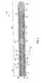
- a standard pre-loaded delivery system 10 comprising an outer sheath 12, a compressed endoluminal device 14 loaded therein, and a conventional stabilizer 16 loaded adjacent to the proximal end 17 of the endoluminal device.
- a standard deployment technique comprises maneuvering the introducer to a desired deployment location and retracting outer sheath 12 so that the endoluminal device is deployed beginning at its distal end and ending at its proximal end.
- Stabilizer 16 stabilizes or prevent retraction of endoluminal device 14 when sheath 12 is retracted, thus effecting deployment of the device into a desired location by forcing relative movement between the sheath and the device.
- Delivery system 10 also may comprise a catheter tip 20 at its distal end attached to an internal shaft 23 that runs through the delivery system through inner lumen 22 in stabilizer 16, as shown in Fig. 1A.
- a stabilizer handle 26 is typically located at the proximal end of stabilizer 16, outside the body lumen.
- Internal shaft 23 may guide the delivery system through the body lumen over a guidewire (not shown) to the area to be repaired, or may be adapted for inflating a balloon (if applicable), and/or for flushing the system.
- a modular self-expanding stent In a procedure to repair an abdominal aortic aneurysm (AAA), use of a modular self-expanding stent involves accurate placement of a terminus of a first stent component in the abdominal aorta just below the renal arteries. A second stent component is then deployed in the first stent component and permitted to extend to a terminus in one of the iliac arteries. It is difficult, however, to ensure accurate placement of the iliac terminus of the second stent component. If the terminus is not placed far enough into the iliac, then the stent may be ineffective. If the terminus extends too far, it may interfere with blood flow in arteries branching from the iliac, such as the internal iliac artery.
- WO 99/47075 and US 5 201 757 disclose deployment devices with anterograde and reterograde sheaths, used for accurate deployment of endoluminal devices.
- an introducer having a retrograde portion and an anterograde portion for deployment of an endoluminal device in a distal location from a proximal location.
- the introducer comprises, in a most basic embodiment, a shaft having a distal tip; an inner sheath mounted concentrically over the shaft with the endoluminal device mounted concentrically over the inner sheath; and an anterograde sheath attached proximally to the distal tip, mounted over the endoluminal device in the anterograde portion of the introducer, and axially moveable relative to the inner sheath by moving the shaft.
- the introducer further comprises anchoring means in at least one of the retrograde portion or the anterograde portion for anchoring the endoluminal device in the deployed configuration during deployment of the device from its proximal end to its distal end.
- the anchoring means comprises an inflatable balloon in the retrograde portion.
- a proximally retractable retrograde sheath may be mounted concentrically over the shaft and inner sheath and may extend axially over the proximal end of the endoluminal device and the balloon.
- a medial sheath may be mounted concentrically between the inner sheath and the retrograde sheath in the retrograde portion of the introducer proximal the balloon.
- the anchoring means comprises a holder in the anterograde portion.
- the holder may be concentrically mounted to the inner sheath and adapted to prevent distal movement of the endoluminal device during advancement of the anterograde shaft.
- the anterograde sheath may extend over an entire length of the endoluminal device.
- the introducer comprises the proximally retractable retrograde sheath and the medial sheath
- the anchoring means comprises an extended portion of a proximal end of the endoluminal device and a notch in one or both of the medial sheath and the retrograde sheath for releasably confining the extended portion between the retrograde sheath and the medial sheath with the retrograde sheath in a first position and for releasing the extended portion with the retrograde sheath in a second, retracted position relative to the medial sheath.
- the anchoring means comprises a tether attached to a proximal end of the endoluminal device.
- the tether may be attached to one of the medial sheath, the retrograde sheath, or the inner sheath.
- the tether may extend proximally from the device a sufficient distance to terminate outside a body lumen through which the introducer is adapted to be introduced.
- the medial sheath may comprise a lateral channel through which the tether extends.
- Still another embodiment of the present invention comprises an introducer having a retrograde portion and an anterograde portion and comprising an inflatable balloon mounted radially inside the retrograde portion for anchoring the endoluminal device during deployment of the device from its proximal end to its distal end.
- the anterograde portion comprises a distal tip and an anterograde sheath attached proximally to the distal tip.
- a shaft attached to the distal tip and extending concentrically through a central lumen defined by the anterograde portion and retrograde portion is adapted for moving the anterograde portion relative to the retrograde portion.
- the endoluminal device is mounted concentrically over the shaft in the central lumen and has a distal end contained by the anterograde portion and a proximal end contained by the retrograde portion.
- the introducer may further comprise an inner sheath mounted concentrically over the shaft underneath the endoluminal device, the inner sheath defining a lumen connected to an inner region of the inflatable balloon for communication of a fluid to the balloon for inflation of the balloon.
- the retrograde portion comprises a proximally retractable retrograde sheath mounted concentrically over the shaft and inner sheath and extending distally over the balloon and a retrograde portion of the endoluminal device.
- the invention a method for deployment of an endoluminal device in a distal location in a body lumen from a proximal location is described.
- the method comprises the steps of inserting an introducer of the present invention into a body lumen, aligning the introducer in a deployment location, extending the shaft to distally advance the anterograde sheath to deploy at least the anterograde portion of the endoluminal device, and then removing the introducer from the body lumen.
- the method comprises aligning the proximal end of the device with the deployment location, and confining the endoluminal device between the anchoring means and the advancing anterograde sheath during advancement of the anterograde sheath.
- the anchoring means are in the retrograde portion, the method comprises anchoring the proximal end during advancement of the anterograde sheath and releasing the proximal end prior to or concurrently with removal of the introducer from the lumen.
- the method comprises inflating the balloon prior to deployment of the anterograde portion of the endoluminal device and deflating the balloon after deployment of the anterograde portion.
- the retrograde sheath is retracted prior to inflating the balloon, such that the balloon is inflated to anchor the proximal end of the endoluminal device against the body lumen.
- the method comprises separating the tether from the endoluminal device prior to or during removal of the introducer from the body.
- the anchoring means comprises an extended portion of the endoluminal device releasably confined in a notch between the retrograde sheath and the medial sheath or between the retrograde sheath and the inner sheath
- the method comprises retracting the retrograde sheath sufficient to release the extended portion from the notch after deployment of the anterograde portion of the endoluminal device.
- an exemplary method comprises aligning the introducer in a deployment location, retracting at least part of the retrograde portion and deploying the proximal end of the endoluminal device.
- the balloon is then inflated to compress the endoluminal device against the lumen wall while the shaft is extended to distally advance the anterograde sheath to deploy a remaining portion of the endoluminal device.
- Introducer 100 comprises a retrograde portion 102 and an anterograde portion 104.
- Shaft 106 may be solid or tubular, and is surrounded by three concentrically positioned sheaths: inner sheath 108, medial sheath 110, and retrograde sheath 112.
- Medial sheath 110 preferably has a fixed position and operates as a radial spacer, separating retrograde sheath distal extension 114 from inner sheath distal extension 116.
- the distal extension 114 of retrograde sheath 112 and distal extension 116 of inner sheath 108 comprise the respective portions of those sheaths located distally of the distal end 111 of medial sheath 110.
- inner sheath or retrograde sheath may provide such spacing.
- inner sheath may have a stepped outside diameter or retrograde sheath may have a stepped inside diameter, such as created by medial sheath being fused to either inner sheath or retrograde sheath, or by any other method that creates an equivalent structure.
- Radial space 118 between retrograde sheath 112 and inner sheath 108 may be sufficiently large to allow room for a radial-force-exerting device, such as balloon 120.
- Inner sheath 108 preferably has a fixed position and may include a lumen for communicating pressurized fluid to balloon 120.
- balloon 120 and proximal end 131 of device 130 may be part of anterograde portion 104 and covered by anterograde sheath 126.
- Anterograde portion 104 of introducer 100 includes a distal extension 122 of shaft 106 and distal extension 116 of inner sheath 108.
- Distal extension 122 of shaft 106 terminates with an attachment to radial spacer 125 connected to distal tip 124.
- Distal tip 124 is coupled to anterograde sheath 126, which extends proximally from distal tip 124, and is positioned concentrically about shaft distal extension 122 and inner sheath distal extension 116.
- Radial spacer 125 creates an area 128 into which an endoluminal device 130, such as a stent graft, can be loaded.
- Retrograde sheath 112 and anterograde sheath 126 may have a lateral space 132 therebetween, the sheaths may abut one another (not shown) without any space 132, or the sheaths may laterally overlap one another as depicted by dashed lines 140 in Fig. 2. Dashed lines 140 show a proximal extension of anterograde sheath 126 that overlaps retrograde sheath 112. In an alternative embodiment, a similar distal extension (not shown) of retrograde sheath 112 may laterally overlap anterograde sheath 126.
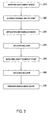
- an exemplary method for using introducer 100 is depicted in the flowchart shown in Fig. 3.
- the method may be performed, for example, in an operating room or an angiographic suite, preferably under fluoroscopic guidance as is known in the art.
- the introducer is inserted into a body lumen, as indicated in step 210, distal tip 124 first, from a proximal access site, such as a femoral artery or iliac artery, for vascular deployment.
- a proximal access site such as a femoral artery or iliac artery
- the introducer is threaded into the lumen over a guidewire (not shown) as is well known in the art.
- the access site may be surgically exposed and punctured with, for example, an 18-gauge needle as is known in the art.
- proximal end 131 of endoluminal device 130 is aligned in an appropriate deployment position. Fluoroscopic guidance and/or a guide wire may be used to guide proximal end 131 into the desired position.
- endoluminal device 130 is an AAA stent graft
- proximal end 131 of device 130 is positioned in the iliac (not shown), preferably just above a branch of the internal iliac artery (not shown).
- step 230 retrograde sheath 112 is retracted at least far enough to expose proximal end 131 of device 130 and balloon 120.
- the anterograde sheath 126 is initially advanced far enough to expose the proximal end and balloon.
- Balloon 120 is inflated in step 240, such as by pressurizing balloon 120 with fluid communicated via a lumen in inner sheath 108, to exert radial force that compresses the retrograde portion 133 of device 130 against the lumen wall (not shown).
- the various lumens are shown concentrically, other configurations, including side-by-side lumen can be used.
- step 250 shaft 106 is extended distally to deploy the anterograde portion 135 of device 130.
- the guidewire and retrograde sheath 112 may typically be locked together to prevent movement of the retrograde sheath or the guidewire during extension of the shaft.
- the "retrograde portion" of device 130 refers to any portion initially covered by the retrograde sheath (as shown in Fig. 2) or any portion underlied by balloon 120 and any portion proximal thereof (as shown in Fig.
- Balloon 120 is then deflated in step 260 and introducer 100 is removed from the lumen in accordance with step 270. If desired, prior to removal from the lumen, balloon 120 may be used for modeling device 130 to better conform to the contours of the lumen wall, as is known in the art.
- introducer 100 and the method depicted in Fig. 3 provides means for accurately placing the proximal end of an endoluminal device.
- a notch 150 may be located in medial sheath 110a.
- a proximally extended portion 131a of device 130a such as an extended cell or a loop, is fixed within notch 150.
- the retrograde sheath 112 is only retracted in step 230 until the proximal end 131 of stent 130 deploys, except for proximally extended portion 131a.
- a radiopaque deployment marker (not shown) may be used to mark the end 131 so that the retrograde sheath is not retracted too far.
- Steps 240 and 260 are omitted from the method steps, as proximally extended portion 131 a remains compressed in notch 150 between medial sheath 110a and retrograde sheath 112 to hold the proximal end 131 of device 130 in place until the distal portion of the stent has been deployed. Then, prior to removing deployment device in step 270, retrograde sheath 112 is retracted the remaining distance necessary to release proximally extended portion 131a from notch 150.
- a tether 152 may be used for anchoring. Distal end 153 of tether 152 is attached to proximal end 131 of device 130 and proximal end 154 of the tether may be attached to the distal end of either retrograde sheath 112 (as shown in Fig. 5A) or medial sheath 110 (not shown), or to an intermediate portion of inner sheath 108 (shown in Fig. 5C). Tether 152 may be attached to device 130 and sheath 112 or 110 in any way known in the art, such as by gluing, suturing, stapling, welding, heat shrinking, and the like.
- the tether may comprise any type of material known in the art, including metal or non-metal filaments.
- the tether is attached to the device in such a way that it is readily detachable from the device when desired. Suitable mechanisms for detachably connecting a wire to an implantable device are described in U.S. Patents No. 5,354,295 and No. 5,122,136 to Guglielmi et al., as well as in U.S. Patent Application Serial No. Serial No. 09/852,524, filed on May 10, 2001.
- tether 152 may be employed in any way known in the art, including extending proximally all the way back to the access location outside the body lumen.
- medial sheath 110a may have a lateral channel running its entire length into which tether 152 may extend.
- tether 152 may connect to a power supply or a handle for exerting tensional or torsional force, as described in the '524 Application.
- the method is carried out as shown in Fig. 3 up to step 230, at which point the retrograde sheath 112 is retracted until proximal end 131 of the device 130 deploys, with tether 152 holding proximal end 131 in place.
- the guidewire is then typically locked with retrograde sheath 112 to prevent further movement of the retrograde sheath 112, and anterograde sheath 126 is advanced by advancing shaft 106 to deploy the anterograde portion of device 130.
- the remainder of retrograde sheath 112 is retracted as part of step 270 to release device 130 from tether 152.
- proximal end 154 of tether 152 is attached to medial sheath 110 instead of retrograde sheath 112, the medial sheath may be retracted, or if the medial sheath is not retractable, the entire introducer may be retracted to release device 130 from tether 152 in step 270.
- FIG. 6 Another introducer embodiment 600 is shown in Fig. 6.
- all of the components are essentially the same as in embodiment 100, except that instead of a combination of balloon 120 and retrograde sheath 112 at the proximal end, there is a holder 602 near the distal end of inner sheath extension 116.
- Anterograde sheath 126 (and thus anterograde portion 104 of introducer 600) extends to the proximal end 131 of device 130.
- Holder 602 may comprise any material known in the art and may have any geometry known in the art sufficient to hold device 130 in place while anterograde sheath is advanced. A number of geometries and materials useful for holding a stent in place from inside the stent are described in U.S. Application Serial No.
- holder 602 may be a sleeve of a relatively higher friction material than sheath 126 such that device 130 is frictionally retained while sheath 126 advances.
- holder 602 may comprise one or more radial protrusions that exerts an axial restraining force against individual members of device 130.
- Other structures or combinations of multiple structures may also be used as holders.
- a holder 602 at or near the distal end of device 130 as shown in Fig. 6 may be beneficial for combination with a balloon at or near the proximal end of the device as shown in Fig. 7.
- Such a holder 602 may minimize potential distal advancement of proximal end 131 of device 130 during the initial advancement of sheath 126 to expose balloon 120, as may otherwise potentially occur as a result of frictional contact between the anterograde sheath and the device.
- balloon 120 may also be provided with a greater frictional engagement force than sheath 126 so that device 130 tends to stay with the balloon rather than move with the sheath.
- Such a greater frictional engagement force may be the result of a higher coefficient of friction, for example.
- the method of using introducer 600 involves steps 210, 220, 250, and 270, without any of the steps relating to the balloon or the retrograde shaft.
- the embodiment shown in Fig. 6 may comprise a minimal set of components comprising shaft 106, inner sheath 108, holder 602 mounted directly to the inner sheath 108, and tip 124 attached to anterograde sheath 126.
- the remaining components shown in Fig. 6 are optional.
- Holder 602 is not limited to restraining only the distal end of device 130.
- holder 602 may extend the length of device 130, an embodiment that may be particularly useful with devices having a relatively low column strength.
- a hybrid of introducers 100 and 600 may also be provided comprising both a holder 602 and a balloon 120 or other anchoring means at proximal end 131 of device 130, with anterograde sheath 126 extending over the proximal end of the device. In such a configuration comprising a balloon, the deployment method follows the method steps in the order shown in Fig.
- the method comprises advancing anterograde sheath a sufficient distance to uncover balloon 120, and then inflating the balloon at step 240 and continuing on with the remainder of the method steps.
- balloon 120 once inflated, is capable of anchoring device 130, holder 602 may be located closer to proximal end 131 of the device so that it engages the device only during the initial advancement of anterograde sheath 126 prior to inflation of the balloon.
- Tethered or extended-portion-and-notch embodiments may also be provided with anterograde sheath 126 extending to the proximal end of endoluminal device 130.
- an extended-portion-and-notch embodiment shown in Fig. 4B there may be no medial sheath, such that retrograde sheath 112a directly contacts inner sheath 108a, and the notch 150 may be in inner sheath 108a, retrograde sheath 112a, or may comprise notch portions 150a and 150b in each, respectively, as shown in Fig. 4B.
- the medial sheath may optionally be present, such as to preserve a constant radial profile throughout the introducer, in which case the notch or a portion of the notch may be located in one or both of the retrograde sheath and the medial sheath.
- the method of using such an embodiment comprises inserting the device in step 210, aligning the proximal end in step 220, extending the shaft to deploy the device 250, and then retracting the retrograde sheath in step 230 a sufficient distance to release the extended portion from the notch.
- tether 152 may just be attached to an intermediate portion of inner sheath 108 as shown in Fig. 5C, or may extend freely (not shown) through the lumen back through the access location and outside the lumen to some means for manipulating the tether, such as the means shown and described in '524 Application.
- tether 152 is wrapped about inner sheath 108 in a manner than fixes it axially and may be further anchored in place with an adhesive.
- Notch 155 in tether provides a predetermined weak spot so that the retraction of the introducer is sufficient to break the tether at the notch. It is important that the amount of force required to break tether 152 at a preferred location, such as notch 155, is less than the amount of force that will break the tether in other locations or remove the affixation of the tether to inner sheath, more than the amount of force necessary to hold proximal end 131 of endoluminal device 130 in place during deployment of its distal end (so that it does not break prematurely), and less than the amount of force that will axially move device 130 once deployed in the lumen (so that breaking the tether does not take the deployed device out of its proper alignment).
- the tether may also be affixed in a slipknot that requires an amount of force to undo the knot that does not break the tether, pull the deployed device out of alignment, or undo prematurely.
- the dimensions of the introducer may be optimized to prevent damage caused by the anterograde portion being too long.
- One way of shortening the anterograde portion for a particular application is to lengthen the retrograde portion.
- anterograde portion and retrograde portions may extend over equal lengths of the device, or portion of the device over which the retrograde portion extends may be longer than the portion over which the anterograde portion extends.
- Such embodiments for example an introducer wherein the retrograde and anterograde portions extend over equal lengths of the device, may be useful where the location of the proximal end of the device is less important than aligning the middle of the device with a certain region of a lumen.
Landscapes
- Health & Medical Sciences (AREA)
- Engineering & Computer Science (AREA)
- Biomedical Technology (AREA)
- General Health & Medical Sciences (AREA)
- Veterinary Medicine (AREA)
- Transplantation (AREA)
- Heart & Thoracic Surgery (AREA)
- Vascular Medicine (AREA)
- Life Sciences & Earth Sciences (AREA)
- Animal Behavior & Ethology (AREA)
- Cardiology (AREA)
- Public Health (AREA)
- Oral & Maxillofacial Surgery (AREA)
- Prostheses (AREA)
- Media Introduction/Drainage Providing Device (AREA)
- Vehicle Body Suspensions (AREA)
- Steering Control In Accordance With Driving Conditions (AREA)
- Paper (AREA)
- Mechanical Treatment Of Semiconductor (AREA)
- Surgical Instruments (AREA)
Claims (32)
- Introducteur (100, 600) comportant une partie arrière (102) et une partie avant (104), pour le déploiement d'un dispositif endoluminal (130) dans une lumière du corps dans un emplacement distal depuis un emplacement proximal, le dispositif (130) ayant une configuration comprimée et une configuration déployée, l'introducteur (100, 600) comprenant :une tige (106) comportant une extrémité distale (124) ;une gaine intérieure (108) montée de manière concentrique sur la tige (106), le dispositif endoluminal (130) étant monté de manière concentrique sur la gaine intérieure (108) dans la configuration comprimée ;une gaine avant (126) fixée de manière proximale à l'extrémité distale (124), montée sur une partie avant du dispositif endoluminal (130) dans la partie avant (104) de l'introducteur (100, 600), la gaine avant (126) étant configurée de façon à ce que le mouvement distal de la gaine avant (126) découvre la partie avant du dispositif endoluminal (130) contenue dedans, caractérisé parun moyen d'ancrage (120, 150, 152, 602) situé dans au moins l'une de la partie arrière (102) ou de la partie avant (104) pour ancrer l'extrémité proximale (131) du dispositif endoluminal (130) dans la configuration déployée, à l'extérieur de l'introducteur (100, 600) et en contact avec la lumière du corps et pour minimiser le mouvement axial relatif entre l'extrémité proximale (131) du dispositif (130) et la lumière du corps durant le dénudage d'une partie restante du dispositif endoluminal (130) distale de l'extrémité proximale (131).
- Introducteur (100, 600) selon la revendication 1, dans lequel le moyen d'ancrage comprend un ballonnet gonflable (120) à une ou près d'une extrémité proximale (131) du dispositif (130).
- Introducteur (100, 600) selon la revendication 2, dans lequel la gaine intérieure (108) définit un conduit relié à une zone intérieure du ballonnet gonflable (120) pour faire communiquer un fluide vers le ballonnet (120) afin de gonfler le ballonnet (120).
- Introducteur (100, 600) selon la revendication 2, dans lequel le ballonnet gonflable (120) est monté de manière concentrique sous une partie arrière (102) du dispositif endoluminal (130).
- Introducteur (100, 600) selon la revendication 4 comprenant en outre une gaine arrière rétractable de façon proximale (112, 612) montée de manière concentrique sur la tige (106) et la gaine intérieure (108) située dans la partie arrière (102) de l'élément d'introduction (100, 600) et s'étendant de manière distale sur le ballonnet (120) et une partie arrière (102) du dispositif endoluminal (130).
- Introducteur (100, 600) selon la revendication 5 comprenant en outre une gaine intermédiaire (110) montée de manière concentrique entre la gaine intérieure (108) et la gaine arrière (112, 612) dans la partie arrière (102) de l'introducteur (100, 600).
- Introducteur (100, 600) selon la revendication 6, dans lequel la gaine intermédiaire (110) comporte une extrémité distale (111) qui se termine à proximité du ballonnet (120).
- Introducteur (100, 600) selon la revendication 4, dans lequel la gaine avant (126) s'étend de manière proximale sur le ballonnet (120) et une partie arrière (133) du dispositif endoluminal (130).
- Introducteur (100, 600) selon la revendication 1 comprenant en outre un élément d'espacement radial (125) pour fournir un espace suffisant entre la gaine intérieure (108) et la gaine avant (126) pour contenir le dispositif endoluminal (130).
- Introducteur (100, 600) selon la revendication 9, dans lequel l'élément d'espacement radial (125) est fixé de manière proximale à l'extrémité distale (124).
- Introducteur (100, 600) selon la revendication 1, dans lequel le moyen d'ancrage comprend un support (602) dans la partie avant (104).
- Introducteur (100, 600) selon la revendication 11, dans lequel le support (602) est monté de manière concentrique sur la gaine intérieure (108) et est adapté pour empêcher le mouvement distal du dispositif endoluminal (130) durant la progression distale de la gaine avant (126).
- Introducteur (100, 600) selon la revendication 12, dans lequel le dispositif endoluminal (130) a une certaine longueur et le support (602) a une certaine longueur qui est inférieure à la longueur du dispositif endoluminal (130).
- Introducteur (100, 600) selon la revendication 11, dans lequel la gaine avant (126) s'étend sur toute la longueur du dispositif endoluminal (130).
- Introducteur (100, 600) selon la revendication 1, dans lequel la gaine avant (126) s'étend sur toute la longueur du dispositif endoluminal (130).
- Introducteur (100, 600) selon la revendication 1 comprenant en outre :une gaine arrière rétractable de façon proximale (112, 612) montée de manière concentrique sur la tige (106) et la gaine intérieure (108) et s'étendant axialement sur une partie arrière (133) du dispositif endoluminal (130) ; etune gaine intermédiaire (110) montée de manière concentrique entre la gaine intérieure (108) et la gaine arrière (112, 612) dans la partie arrière (102) de l'introducteur (100, 600) et qui se termine à proximité d'une extrémité proximale (131) du dispositif endoluminal (130).
- Introducteur (100, 600) selon la revendication 16, dans lequel le moyen d'ancrage comprend une partie étendue de façon proximale (131a) du dispositif endoluminal (130) et une encoche (150) dans la gaine intermédiaire (110a) pour maintenir la partie étendue (131a) entre la gaine arrière (112a) et la gaine intermédiaire (110a), lorsque la gaine arrière (112a) se trouve dans une première position, et pour relâcher la partie étendue (131a), lorsque la gaine arrière (112a) se trouve dans une seconde position rétractée par rapport à la gaine intermédiaire (110a).
- Introducteur (100, 600) selon la revendication 1 comprenant en outre une gaine arrière rétractable de façon proximale (112a) montée de manière concentrique sur la tige (106) et une gaine intérieure (108a), et dans lequel le moyen d'ancrage comprend une partie étendue de façon proximale (131a) du dispositif endoluminal (130) et une encoche (150a, 150b) dans la gaine intérieure (108a) ou dans la gaine arrière (112a) ou dans les deux pour maintenir la partie étendue (131a) entre la gaine arrière (112a) et la gaine intérieure (108a), lorsque la gaine arrière (112a) se trouve dans une première position, et pour relâcher la partie étendue (131a), lorsque la gaine arrière (112a) se trouve dans une seconde position rétractée par rapport à la gaine intérieure (108a).
- Introducteur (100, 600) selon la revendication 1 comprenant en outre :une gaine arrière rétractable de façon proximale (112a) montée de manière concentrique sur la tige (106) et la gaine intérieure (108a) ; etune gaine intermédiaire (110a) montée de manière concentrique entre la gaine intérieure (108a) et la gaine arrière (112a) dans la partie arrière (102) de l'introducteur (100, 600) et qui se termine à proximité d'une extrémité proximale (131) du dispositif endoluminal (130) ;dans lequel le moyen d'ancrage comprend une partie étendue de façon proximale (131a) du dispositif endoluminal (130) et une encoche (150a, 150b) dans la gaine intermédiaire (110a) ou dans la gaine arrière (112a) ou dans les deux pour maintenir la partie étendue (131a) entre la gaine arrière (112a) et la gaine intermédiaire (110a), lorsque la gaine arrière (112a) se trouve dans une première position, et pour relâcher la partie étendue (131a), lorsque la gaine arrière (112a) se trouve dans une seconde position rétractée par rapport à la gaine intermédiaire (110a).
- Introducteur (100, 600) selon la revendication 1, dans lequel le moyen d'ancrage comprend une attache (152) fixée à une extrémité proximale (131) du dispositif endoluminal (130).
- Introducteur (100, 600) selon la revendication 20 comprenant en outre une gaine arrière rétractable de façon proximale (112, 612) montée de manière concentrique sur la tige (106) et la gaine intérieure (108) et dans lequel l'attache (152) est fixée à une partie de la gaine intérieure (108).
- Introducteur (100, 600) selon la revendication 21, dans lequel l'attache (152) s'étend de manière proximale depuis le dispositif (130) d'une distance suffisante pour se terminer en dehors d'une lumière du corps par laquelle l'introducteur (100, 600) est adapté pour être introduit.
- Introducteur (100, 600) selon la revendication 21, dans lequel une extrémité proximale de l'attache (152) est fixée à un moyen pour appliquer un courant électrique, ou une force de torsion ou de tension.
- Introducteur (100, 600) selon la revendication 20 comprenant en outre :une gaine arrière rétractable de façon proximale (112, 612) montée de manière concentrique sur la tige (106) et la gaine intérieure (108) et s'étendant axialement sur une extrémité proximale (131) du dispositif endoluminal (130) ; etune gaine intermédiaire (110) montée de manière concentrique entre la gaine intérieure (108) et la gaine arrière (112, 612) dans la partie arrière (102) de l'introducteur (100, 600) et qui se termine à proximité de l'extrémité proximale (131) du dispositif endoluminal.
- Introducteur (100, 600) selon la revendication 24, dans lequel l'attache (152) est fixée à la gaine intermédiaire (110), à la gaine arrière (112, 612) ou à la gaine intérieure (108).
- Introducteur (100, 600) selon la revendication 25, dans lequel l'attache (152) s'étend de manière proximale depuis le dispositif (130) d'une distance suffisante pour se terminer en dehors d'une lumière du corps par laquelle l'introducteur (100, 600) est adapté pour être introduit.
- Introducteur (100, 600) selon la revendication 26, dans lequel la gaine intermédiaire (110) comprend un canal latéral dans lequel l'attache (152) s'étend.
- Introducteur (100, 600) selon la revendication 20, dans lequel la gaine avant (126) s'étend sur toute la longueur du dispositif endoluminal (130).
- Introducteur (100, 600) selon la revendication 1 comprenant en outre une gaine arrière rétractable de façon proximale (112, 612) montée de manière concentrique sur la tige (106) et la gaine intérieure (108) et s'étendant de manière axiale sur une extrémité proximale (131) du dispositif endoluminal (130).
- Introducteur (100, 600) selon la revendication 29, dans lequel la partie avant (104) s'étend sur une longueur plus grande du dispositif endoluminal (130) que la partie arrière (102).
- Introducteur (100, 600) selon la revendication 29, dans lequel la gaine arrière (112, 612) et la gaine avant (126) sont espacées latéralement l'une de l'autre.
- Introducteur (100, 600) selon la revendication 29, dans lequel la gaine arrière (112, 612) et la gaine avant (126) se chevauchent latéralement l'une l'autre.
Applications Claiming Priority (3)
| Application Number | Priority Date | Filing Date | Title |
|---|---|---|---|
| US81641 | 1993-06-24 | ||
| US10/081,641 US7887573B2 (en) | 2002-02-22 | 2002-02-22 | Method and apparatus for deployment of an endoluminal device |
| PCT/US2003/004832 WO2003071988A1 (fr) | 2002-02-22 | 2003-02-19 | Procede et dispositif permettant la mise en place d'un dispositif endoluminal |
Publications (2)
| Publication Number | Publication Date |
|---|---|
| EP1482866A1 EP1482866A1 (fr) | 2004-12-08 |
| EP1482866B1 true EP1482866B1 (fr) | 2007-03-21 |
Family
ID=27752977
Family Applications (1)
| Application Number | Title | Priority Date | Filing Date |
|---|---|---|---|
| EP03711107A Expired - Lifetime EP1482866B1 (fr) | 2002-02-22 | 2003-02-19 | Dispositif permettant la mise en place d'un dispositif endoluminal |
Country Status (9)
| Country | Link |
|---|---|
| US (3) | US7887573B2 (fr) |
| EP (1) | EP1482866B1 (fr) |
| JP (1) | JP4364647B2 (fr) |
| AT (1) | ATE357196T1 (fr) |
| AU (1) | AU2003215288A1 (fr) |
| CA (1) | CA2476734C (fr) |
| DE (1) | DE60312662T2 (fr) |
| ES (1) | ES2283757T3 (fr) |
| WO (1) | WO2003071988A1 (fr) |
Families Citing this family (88)
| Publication number | Priority date | Publication date | Assignee | Title |
|---|---|---|---|---|
| EP0850607A1 (fr) | 1996-12-31 | 1998-07-01 | Cordis Corporation | Prothèse de valve pour implantation dans des canaux corporels |
| US6454799B1 (en) | 2000-04-06 | 2002-09-24 | Edwards Lifesciences Corporation | Minimally-invasive heart valves and methods of use |
| US6733525B2 (en) | 2001-03-23 | 2004-05-11 | Edwards Lifesciences Corporation | Rolled minimally-invasive heart valves and methods of use |
| US6893460B2 (en) | 2001-10-11 | 2005-05-17 | Percutaneous Valve Technologies Inc. | Implantable prosthetic valve |
| US7892273B2 (en) | 2001-12-03 | 2011-02-22 | Xtent, Inc. | Custom length stent apparatus |
| US7137993B2 (en) | 2001-12-03 | 2006-11-21 | Xtent, Inc. | Apparatus and methods for delivery of multiple distributed stents |
| US7004964B2 (en) * | 2002-02-22 | 2006-02-28 | Scimed Life Systems, Inc. | Apparatus and method for deployment of an endoluminal device |
| US7887573B2 (en) | 2002-02-22 | 2011-02-15 | Boston Scientific Scimed, Inc. | Method and apparatus for deployment of an endoluminal device |
| US6866679B2 (en) | 2002-03-12 | 2005-03-15 | Ev3 Inc. | Everting stent and stent delivery system |
| US7553324B2 (en) * | 2003-10-14 | 2009-06-30 | Xtent, Inc. | Fixed stent delivery devices and methods |
| US7326236B2 (en) | 2003-12-23 | 2008-02-05 | Xtent, Inc. | Devices and methods for controlling and indicating the length of an interventional element |
| US7323006B2 (en) | 2004-03-30 | 2008-01-29 | Xtent, Inc. | Rapid exchange interventional devices and methods |
| US20050246008A1 (en) * | 2004-04-30 | 2005-11-03 | Novostent Corporation | Delivery system for vascular prostheses and methods of use |
| US8267985B2 (en) | 2005-05-25 | 2012-09-18 | Tyco Healthcare Group Lp | System and method for delivering and deploying an occluding device within a vessel |
| US8617234B2 (en) | 2004-05-25 | 2013-12-31 | Covidien Lp | Flexible vascular occluding device |
| CA2758946C (fr) | 2004-05-25 | 2014-10-21 | Tyco Healthcare Group Lp | Implantation d'endoprotheses vasculaires pour l'anevrysme |
| ES2607402T3 (es) | 2004-05-25 | 2017-03-31 | Covidien Lp | Dispositivo de oclusión vascular flexible |
| US20060206200A1 (en) | 2004-05-25 | 2006-09-14 | Chestnut Medical Technologies, Inc. | Flexible vascular occluding device |
| US8623067B2 (en) | 2004-05-25 | 2014-01-07 | Covidien Lp | Methods and apparatus for luminal stenting |
| US8317859B2 (en) | 2004-06-28 | 2012-11-27 | J.W. Medical Systems Ltd. | Devices and methods for controlling expandable prostheses during deployment |
| US20050288766A1 (en) | 2004-06-28 | 2005-12-29 | Xtent, Inc. | Devices and methods for controlling expandable prostheses during deployment |
| EP2965724B1 (fr) | 2005-05-25 | 2018-07-04 | Covidien LP | Systeme destiné a distribuer et deployer un stent a l'interieur d'un vaisseau |
| US8273101B2 (en) | 2005-05-25 | 2012-09-25 | Tyco Healthcare Group Lp | System and method for delivering and deploying an occluding device within a vessel |
| US7670365B2 (en) * | 2005-09-23 | 2010-03-02 | BostonScientific Scimed, Inc. | Secured stent delivery system |
| WO2007100556A1 (fr) | 2006-02-22 | 2007-09-07 | Ev3 Inc. | Systemes de protection embolique munis d'un tamis filtrant radio-opaque |
| EP1998716A4 (fr) | 2006-03-20 | 2010-01-20 | Xtent Inc | Appareil et procédés destinés à la mise en place de segments prothétiques reliés entre eux |
| US20080114437A1 (en) * | 2006-11-13 | 2008-05-15 | Boston Scientific Scimed, Inc. | Self-expanding side branch bifurcated stent |
| US8747459B2 (en) * | 2006-12-06 | 2014-06-10 | Medtronic Corevalve Llc | System and method for transapical delivery of an annulus anchored self-expanding valve |
| US8236045B2 (en) | 2006-12-22 | 2012-08-07 | Edwards Lifesciences Corporation | Implantable prosthetic valve assembly and method of making the same |
| US20080199510A1 (en) * | 2007-02-20 | 2008-08-21 | Xtent, Inc. | Thermo-mechanically controlled implants and methods of use |
| US8486132B2 (en) | 2007-03-22 | 2013-07-16 | J.W. Medical Systems Ltd. | Devices and methods for controlling expandable prostheses during deployment |
| KR100822045B1 (ko) * | 2007-04-23 | 2008-04-15 | (주) 태웅메디칼 | 신체 협착부위 시술용 스텐트 삽입장치 |
| AU2008323540B2 (en) * | 2007-11-15 | 2015-02-12 | W. L. Gore & Associates, Inc. | Hybrid intraluminal device |
| EP2240121B1 (fr) * | 2008-01-16 | 2019-05-22 | St. Jude Medical, Inc. | Système de mise en place et de retrait de valvules cardiaques prothétiques repliables/expansibles |
| EP2265225B1 (fr) | 2008-02-29 | 2013-02-13 | Edwards Lifesciences Corporation | Elément extensible servant à déployer une prothèse |
| US9101503B2 (en) | 2008-03-06 | 2015-08-11 | J.W. Medical Systems Ltd. | Apparatus having variable strut length and methods of use |
| WO2009140437A1 (fr) | 2008-05-13 | 2009-11-19 | Nfocus Neuromedical, Inc. | Systèmes de pose d'implant tressé |
| US8323335B2 (en) | 2008-06-20 | 2012-12-04 | Edwards Lifesciences Corporation | Retaining mechanisms for prosthetic valves and methods for using |
| US8652202B2 (en) | 2008-08-22 | 2014-02-18 | Edwards Lifesciences Corporation | Prosthetic heart valve and delivery apparatus |
| US8690936B2 (en) | 2008-10-10 | 2014-04-08 | Edwards Lifesciences Corporation | Expandable sheath for introducing an endovascular delivery device into a body |
| US8986361B2 (en) * | 2008-10-17 | 2015-03-24 | Medtronic Corevalve, Inc. | Delivery system for deployment of medical devices |
| GB0901496D0 (en) * | 2009-01-29 | 2009-03-11 | Angiomed Ag | Delivery device for delivering a stent device |
| CN102639086A (zh) * | 2009-09-10 | 2012-08-15 | 挪威斯腾特公司 | 包含固定架的血管假体组件及其方法 |
| US8449599B2 (en) | 2009-12-04 | 2013-05-28 | Edwards Lifesciences Corporation | Prosthetic valve for replacing mitral valve |
| US8986363B2 (en) * | 2009-12-30 | 2015-03-24 | Cook Medical Technologies Llc | Proximal release delivery system |
| US8864811B2 (en) * | 2010-06-08 | 2014-10-21 | Veniti, Inc. | Bi-directional stent delivery system |
| US9155619B2 (en) | 2011-02-25 | 2015-10-13 | Edwards Lifesciences Corporation | Prosthetic heart valve delivery apparatus |
| US20120266892A1 (en) * | 2011-04-21 | 2012-10-25 | Hologic, Inc. | Tethered implant and related method of use |
| US9289282B2 (en) | 2011-05-31 | 2016-03-22 | Edwards Lifesciences Corporation | System and method for treating valve insufficiency or vessel dilatation |
| US9072624B2 (en) | 2012-02-23 | 2015-07-07 | Covidien Lp | Luminal stenting |
| US20130226278A1 (en) | 2012-02-23 | 2013-08-29 | Tyco Healthcare Group Lp | Methods and apparatus for luminal stenting |
| US9078659B2 (en) | 2012-04-23 | 2015-07-14 | Covidien Lp | Delivery system with hooks for resheathability |
| US9155647B2 (en) | 2012-07-18 | 2015-10-13 | Covidien Lp | Methods and apparatus for luminal stenting |
| US9724222B2 (en) | 2012-07-20 | 2017-08-08 | Covidien Lp | Resheathable stent delivery system |
| US20140067048A1 (en) | 2012-09-06 | 2014-03-06 | Edwards Lifesciences Corporation | Heart Valve Sealing Devices |
| US9114001B2 (en) | 2012-10-30 | 2015-08-25 | Covidien Lp | Systems for attaining a predetermined porosity of a vascular device |
| US9452070B2 (en) | 2012-10-31 | 2016-09-27 | Covidien Lp | Methods and systems for increasing a density of a region of a vascular device |
| US9943427B2 (en) | 2012-11-06 | 2018-04-17 | Covidien Lp | Shaped occluding devices and methods of using the same |
| US20140142688A1 (en) | 2012-11-20 | 2014-05-22 | Medtronic CV Luxembourg S.a.r.l. | Medical Device Delivery System and Methods of Delivering a Medical Device |
| US9439763B2 (en) | 2013-02-04 | 2016-09-13 | Edwards Lifesciences Corporation | Prosthetic valve for replacing mitral valve |
| US9157174B2 (en) | 2013-02-05 | 2015-10-13 | Covidien Lp | Vascular device for aneurysm treatment and providing blood flow into a perforator vessel |
| US9168129B2 (en) | 2013-02-12 | 2015-10-27 | Edwards Lifesciences Corporation | Artificial heart valve with scalloped frame design |
| ES2699785T3 (es) | 2013-05-20 | 2019-02-12 | Edwards Lifesciences Corp | Dispositivo para la administración de válvula protésica cardiaca |
| US10130500B2 (en) | 2013-07-25 | 2018-11-20 | Covidien Lp | Methods and apparatus for luminal stenting |
| US9782186B2 (en) | 2013-08-27 | 2017-10-10 | Covidien Lp | Vascular intervention system |
| US10045867B2 (en) | 2013-08-27 | 2018-08-14 | Covidien Lp | Delivery of medical devices |
| US9622863B2 (en) | 2013-11-22 | 2017-04-18 | Edwards Lifesciences Corporation | Aortic insufficiency repair device and method |
| US10098734B2 (en) | 2013-12-05 | 2018-10-16 | Edwards Lifesciences Corporation | Prosthetic heart valve and delivery apparatus |
| MX2016016493A (es) * | 2014-05-05 | 2017-12-20 | Endosphere Inc | Dispositivos gastrointestinales duodenales y mecanismos de suministro. |
| US9532870B2 (en) | 2014-06-06 | 2017-01-03 | Edwards Lifesciences Corporation | Prosthetic valve for replacing a mitral valve |
| US10195026B2 (en) | 2014-07-22 | 2019-02-05 | Edwards Lifesciences Corporation | Mitral valve anchoring |
| US10058424B2 (en) | 2014-08-21 | 2018-08-28 | Edwards Lifesciences Corporation | Dual-flange prosthetic valve frame |
| KR101696811B1 (ko) * | 2015-02-10 | 2017-01-17 | 주식회사 엠아이텍 | 카테터 |
| US10064718B2 (en) | 2015-04-16 | 2018-09-04 | Edwards Lifesciences Corporation | Low-profile prosthetic heart valve for replacing a mitral valve |
| US10010417B2 (en) | 2015-04-16 | 2018-07-03 | Edwards Lifesciences Corporation | Low-profile prosthetic heart valve for replacing a mitral valve |
| US10470876B2 (en) | 2015-11-10 | 2019-11-12 | Edwards Lifesciences Corporation | Transcatheter heart valve for replacing natural mitral valve |
| US10376364B2 (en) | 2015-11-10 | 2019-08-13 | Edwards Lifesciences Corporation | Implant delivery capsule |
| US20170290691A1 (en) * | 2016-04-12 | 2017-10-12 | Idev Technologies, Inc. | Stent deployment system including multiple stent-engaging elements |
| EP3478226B1 (fr) | 2016-06-29 | 2022-07-06 | Boston Scientific Scimed, Inc. | Système de pose d'endoprothèse |
| US10376396B2 (en) | 2017-01-19 | 2019-08-13 | Covidien Lp | Coupling units for medical device delivery systems |
| EP3614979A1 (fr) | 2017-04-26 | 2020-03-04 | Boston Scientific Scimed, Inc. | Système de placement à libération proximale et distale |
| US10959846B2 (en) | 2017-05-10 | 2021-03-30 | Edwards Lifesciences Corporation | Mitral valve spacer device |
| US10786377B2 (en) | 2018-04-12 | 2020-09-29 | Covidien Lp | Medical device delivery |
| US11123209B2 (en) | 2018-04-12 | 2021-09-21 | Covidien Lp | Medical device delivery |
| US11071637B2 (en) | 2018-04-12 | 2021-07-27 | Covidien Lp | Medical device delivery |
| US11413176B2 (en) | 2018-04-12 | 2022-08-16 | Covidien Lp | Medical device delivery |
| US11413174B2 (en) | 2019-06-26 | 2022-08-16 | Covidien Lp | Core assembly for medical device delivery systems |
| US11944558B2 (en) | 2021-08-05 | 2024-04-02 | Covidien Lp | Medical device delivery devices, systems, and methods |
Family Cites Families (59)
| Publication number | Priority date | Publication date | Assignee | Title |
|---|---|---|---|---|
| US4140126A (en) * | 1977-02-18 | 1979-02-20 | Choudhury M Hasan | Method for performing aneurysm repair |
| US4787899A (en) * | 1983-12-09 | 1988-11-29 | Lazarus Harrison M | Intraluminal graft device, system and method |
| IT1186142B (it) * | 1984-12-05 | 1987-11-18 | Medinvent Sa | Dispositivo di impiantazione transluminale |
| US4950227A (en) * | 1988-11-07 | 1990-08-21 | Boston Scientific Corporation | Stent delivery system |
| US5148548A (en) | 1989-12-19 | 1992-09-15 | Northern Telecom Limited | Method of monitoring cellular radio channels to avoid adjacent and co-channel interference |
| US5354295A (en) * | 1990-03-13 | 1994-10-11 | Target Therapeutics, Inc. | In an endovascular electrolytically detachable wire and tip for the formation of thrombus in arteries, veins, aneurysms, vascular malformations and arteriovenous fistulas |
| US5122136A (en) * | 1990-03-13 | 1992-06-16 | The Regents Of The University Of California | Endovascular electrolytically detachable guidewire tip for the electroformation of thrombus in arteries, veins, aneurysms, vascular malformations and arteriovenous fistulas |
| US5158548A (en) * | 1990-04-25 | 1992-10-27 | Advanced Cardiovascular Systems, Inc. | Method and system for stent delivery |
| US5078720A (en) * | 1990-05-02 | 1992-01-07 | American Medical Systems, Inc. | Stent placement instrument and method |
| US5628783A (en) | 1991-04-11 | 1997-05-13 | Endovascular Technologies, Inc. | Bifurcated multicapsule intraluminal grafting system and method |
| US5693084A (en) | 1991-10-25 | 1997-12-02 | Cook Incorporated | Expandable transluminal graft prosthesis for repair of aneurysm |
| US5201757A (en) * | 1992-04-03 | 1993-04-13 | Schneider (Usa) Inc. | Medial region deployment of radially self-expanding stents |
| US6090072A (en) * | 1992-10-15 | 2000-07-18 | Scimed Life Systems, Inc. | Expandable introducer sheath |
| US5480423A (en) * | 1993-05-20 | 1996-01-02 | Boston Scientific Corporation | Prosthesis delivery |
| CA2125258C (fr) | 1993-08-05 | 1998-12-22 | Dinah B Quiachon | Systeme de greffe intraluminale multicapsulaire et methode |
| US5409495A (en) * | 1993-08-24 | 1995-04-25 | Advanced Cardiovascular Systems, Inc. | Apparatus for uniformly implanting a stent |
| US5445646A (en) * | 1993-10-22 | 1995-08-29 | Scimed Lifesystems, Inc. | Single layer hydraulic sheath stent delivery apparatus and method |
| US5989280A (en) * | 1993-10-22 | 1999-11-23 | Scimed Lifesystems, Inc | Stent delivery apparatus and method |
| US5609627A (en) * | 1994-02-09 | 1997-03-11 | Boston Scientific Technology, Inc. | Method for delivering a bifurcated endoluminal prosthesis |
| US6039749A (en) * | 1994-02-10 | 2000-03-21 | Endovascular Systems, Inc. | Method and apparatus for deploying non-circular stents and graftstent complexes |
| US5415664A (en) * | 1994-03-30 | 1995-05-16 | Corvita Corporation | Method and apparatus for introducing a stent or a stent-graft |
| WO1995029646A1 (fr) * | 1994-04-29 | 1995-11-09 | Boston Scientific Corporation | Extenseur prothetique medical et son procede de fabrication |
| US5456694A (en) * | 1994-05-13 | 1995-10-10 | Stentco, Inc. | Device for delivering and deploying intraluminal devices |
| US5683451A (en) * | 1994-06-08 | 1997-11-04 | Cardiovascular Concepts, Inc. | Apparatus and methods for deployment release of intraluminal prostheses |
| US5824041A (en) * | 1994-06-08 | 1998-10-20 | Medtronic, Inc. | Apparatus and methods for placement and repositioning of intraluminal prostheses |
| CA2201128C (fr) * | 1994-10-27 | 2000-10-24 | Jeffrey A. Helgerson | Systeme de mise en place d'une prothese endovasculaire |
| AU3783195A (en) * | 1994-11-15 | 1996-05-23 | Advanced Cardiovascular Systems Inc. | Intraluminal stent for attaching a graft |
| CA2163708C (fr) * | 1994-12-07 | 2007-08-07 | Robert E. Fischell | Systeme de catheter integre a double fonction pour angioplastie percutanee transluminale et insertion d'un extenseur |
| US5662675A (en) * | 1995-02-24 | 1997-09-02 | Intervascular, Inc. | Delivery catheter assembly |
| CA2171896C (fr) * | 1995-03-17 | 2007-05-15 | Scott C. Anderson | Extenseur a ancrage multiple |
| US5591228A (en) * | 1995-05-09 | 1997-01-07 | Edoga; John K. | Methods for treating abdominal aortic aneurysms |
| US5807101A (en) * | 1996-01-17 | 1998-09-15 | Scalzo; Josephine | Universal occlusal matrix |
| US6022336A (en) * | 1996-05-20 | 2000-02-08 | Percusurge, Inc. | Catheter system for emboli containment |
| US5980530A (en) * | 1996-08-23 | 1999-11-09 | Scimed Life Systems Inc | Stent delivery system |
| US5968069A (en) * | 1996-08-23 | 1999-10-19 | Scimed Life Systems, Inc. | Stent delivery system having stent securement apparatus |
| DK176341B1 (da) | 1996-09-06 | 2007-08-27 | Cook William Europ | Aggregat til transluminal indföring af en rörformet stent, og en endovaskulær graftindretning |
| US5860998A (en) * | 1996-11-25 | 1999-01-19 | C. R. Bard, Inc. | Deployment device for tubular expandable prosthesis |
| US5817101A (en) * | 1997-03-13 | 1998-10-06 | Schneider (Usa) Inc | Fluid actuated stent delivery system |
| AUPO700897A0 (en) | 1997-05-26 | 1997-06-19 | William A Cook Australia Pty Ltd | A method and means of deploying a graft |
| EP1039944B1 (fr) * | 1997-12-19 | 2008-02-20 | Cordis Corporation | Systeme de catheter avec fullerenes |
| US5873907A (en) * | 1998-01-27 | 1999-02-23 | Endotex Interventional Systems, Inc. | Electrolytic stent delivery system and methods of use |
| US6533807B2 (en) * | 1998-02-05 | 2003-03-18 | Medtronic, Inc. | Radially-expandable stent and delivery system |
| EP0943300A1 (fr) * | 1998-03-17 | 1999-09-22 | Medicorp S.A. | Dispositif pour la mise en place d'un stent de manière réversible |
| US6102942A (en) * | 1998-03-30 | 2000-08-15 | Endovascular Technologies, Inc. | Stent/graft deployment catheter with a stent/graft attachment mechanism |
| US6520983B1 (en) | 1998-03-31 | 2003-02-18 | Scimed Life Systems, Inc. | Stent delivery system |
| WO2000071058A1 (fr) * | 1999-05-20 | 2000-11-30 | Boston Scientific Limited | Systeme de pose d'endoprothese avec stabilisateur encastre et procede de chargement et d'utilisation |
| DE19936980C1 (de) | 1999-08-05 | 2001-04-26 | Aesculap Ag & Co Kg | Einführkatheter für Gefäßprothesen |
| US6613075B1 (en) * | 1999-10-27 | 2003-09-02 | Cordis Corporation | Rapid exchange self-expanding stent delivery catheter system |
| US6610087B1 (en) * | 1999-11-16 | 2003-08-26 | Scimed Life Systems, Inc. | Endoluminal stent having a matched stiffness region and/or a stiffness gradient and methods for providing stent kink resistance |
| US6585758B1 (en) * | 1999-11-16 | 2003-07-01 | Scimed Life Systems, Inc. | Multi-section filamentary endoluminal stent |
| US6290710B1 (en) * | 1999-12-29 | 2001-09-18 | Advanced Cardiovascular Systems, Inc. | Embolic protection device |
| US6322586B1 (en) * | 2000-01-10 | 2001-11-27 | Scimed Life Systems, Inc. | Catheter tip designs and method of manufacture |
| US20030050684A1 (en) * | 2001-09-10 | 2003-03-13 | Abrams Robert M. | Internal restraint for delivery of self-expanding stents |
| US6582460B1 (en) * | 2000-11-20 | 2003-06-24 | Advanced Cardiovascular Systems, Inc. | System and method for accurately deploying a stent |
| US6544223B1 (en) * | 2001-01-05 | 2003-04-08 | Advanced Cardiovascular Systems, Inc. | Balloon catheter for delivering therapeutic agents |
| US6716238B2 (en) * | 2001-05-10 | 2004-04-06 | Scimed Life Systems, Inc. | Stent with detachable tethers and method of using same |
| US7235095B2 (en) * | 2002-02-22 | 2007-06-26 | Scimed Life Systems, Inc. | Method and system for deploying multi-part endoluminal devices |
| US7887573B2 (en) | 2002-02-22 | 2011-02-15 | Boston Scientific Scimed, Inc. | Method and apparatus for deployment of an endoluminal device |
| US7004964B2 (en) * | 2002-02-22 | 2006-02-28 | Scimed Life Systems, Inc. | Apparatus and method for deployment of an endoluminal device |
-
2002
- 2002-02-22 US US10/081,641 patent/US7887573B2/en not_active Expired - Fee Related
-
2003
- 2003-02-19 JP JP2003570736A patent/JP4364647B2/ja not_active Expired - Fee Related
- 2003-02-19 ES ES03711107T patent/ES2283757T3/es not_active Expired - Lifetime
- 2003-02-19 CA CA2476734A patent/CA2476734C/fr not_active Expired - Fee Related
- 2003-02-19 WO PCT/US2003/004832 patent/WO2003071988A1/fr active IP Right Grant
- 2003-02-19 DE DE60312662T patent/DE60312662T2/de not_active Expired - Lifetime
- 2003-02-19 AT AT03711107T patent/ATE357196T1/de not_active IP Right Cessation
- 2003-02-19 AU AU2003215288A patent/AU2003215288A1/en not_active Abandoned
- 2003-02-19 EP EP03711107A patent/EP1482866B1/fr not_active Expired - Lifetime
-
2006
- 2006-02-27 US US11/363,015 patent/US7892272B2/en not_active Expired - Fee Related
-
2011
- 2011-01-08 US US12/987,083 patent/US20110106235A1/en not_active Abandoned
Also Published As
| Publication number | Publication date |
|---|---|
| US7887573B2 (en) | 2011-02-15 |
| US20110106235A1 (en) | 2011-05-05 |
| US7892272B2 (en) | 2011-02-22 |
| WO2003071988A1 (fr) | 2003-09-04 |
| ATE357196T1 (de) | 2007-04-15 |
| JP4364647B2 (ja) | 2009-11-18 |
| CA2476734A1 (fr) | 2003-09-04 |
| JP2005518248A (ja) | 2005-06-23 |
| DE60312662D1 (de) | 2007-05-03 |
| AU2003215288A1 (en) | 2003-09-09 |
| US20030163155A1 (en) | 2003-08-28 |
| CA2476734C (fr) | 2010-05-11 |
| ES2283757T3 (es) | 2007-11-01 |
| EP1482866A1 (fr) | 2004-12-08 |
| US20060142837A1 (en) | 2006-06-29 |
| DE60312662T2 (de) | 2007-11-29 |
Similar Documents
| Publication | Publication Date | Title |
|---|---|---|
| EP1482866B1 (fr) | Dispositif permettant la mise en place d'un dispositif endoluminal | |
| US7235095B2 (en) | Method and system for deploying multi-part endoluminal devices | |
| US7331985B2 (en) | Apparatus and method for deployment of an endoluminal device | |
| JP3441090B2 (ja) | 分岐を有する血管内移植片およびこの移植片を展開する装置 | |
| US6808534B1 (en) | Collapsible jacket guard | |
| US7393357B2 (en) | Endovascular stent graft | |
| US6926732B2 (en) | Stent delivery device and method | |
| EP1086664B1 (fr) | Appareil de mise en place d'une prothèse endoluminale | |
| US7527645B2 (en) | Delivery system for endoluminal implant | |
| EP1894545B1 (fr) | Dispositif de mise en place d'implants multiples in vivo | |
| US20040158308A1 (en) | Delivery catheter for ribbon-type prosthesis and methods of use | |
| JPH08322943A (ja) | シース | |
| EP1051135A1 (fr) | Systeme et procede relatifs a la greffe endoluminale de vaisseaux a deux branches ou ramifies | |
| AU2001245696A1 (en) | Endovascular stent graft | |
| WO1996025125A1 (fr) | Systeme de deploiement d'extenseur d'endoprothese/greffe | |
| JPH0759802A (ja) | 多カプセル管腔内移植装置 | |
| EP3058901A1 (fr) | Introducteur d'implant à fil déclencheur hélicoïdale | |
| CA2300743A1 (fr) | Systeme de greffe endoluminale avec plusieurs dispositifs de retention |
Legal Events
| Date | Code | Title | Description |
|---|---|---|---|
| PUAI | Public reference made under article 153(3) epc to a published international application that has entered the european phase |
Free format text: ORIGINAL CODE: 0009012 |
|
| 17P | Request for examination filed |
Effective date: 20040909 |
|
| AK | Designated contracting states |
Kind code of ref document: A1 Designated state(s): AT BE BG CH CY CZ DE DK EE ES FI FR GB GR HU IE IT LI LU MC NL PT SE SI SK TR |
|
| AX | Request for extension of the european patent |
Extension state: AL LT LV MK RO |
|
| RIC1 | Information provided on ipc code assigned before grant |
Ipc: A61F 2/84 20060101AFI20060712BHEP |
|
| RTI1 | Title (correction) |
Free format text: APPARATUS FOR DEPLOYMENT OF AN ENDOLUMINAL DEVICE |
|
| GRAP | Despatch of communication of intention to grant a patent |
Free format text: ORIGINAL CODE: EPIDOSNIGR1 |
|
| GRAS | Grant fee paid |
Free format text: ORIGINAL CODE: EPIDOSNIGR3 |
|
| GRAA | (expected) grant |
Free format text: ORIGINAL CODE: 0009210 |
|
| AK | Designated contracting states |
Kind code of ref document: B1 Designated state(s): AT BE BG CH CY CZ DE DK EE ES FI FR GB GR HU IE IT LI LU MC NL PT SE SI SK TR |
|
| PG25 | Lapsed in a contracting state [announced via postgrant information from national office to epo] |
Ref country code: FI Free format text: LAPSE BECAUSE OF FAILURE TO SUBMIT A TRANSLATION OF THE DESCRIPTION OR TO PAY THE FEE WITHIN THE PRESCRIBED TIME-LIMIT Effective date: 20070321 Ref country code: CH Free format text: LAPSE BECAUSE OF FAILURE TO SUBMIT A TRANSLATION OF THE DESCRIPTION OR TO PAY THE FEE WITHIN THE PRESCRIBED TIME-LIMIT Effective date: 20070321 Ref country code: SI Free format text: LAPSE BECAUSE OF FAILURE TO SUBMIT A TRANSLATION OF THE DESCRIPTION OR TO PAY THE FEE WITHIN THE PRESCRIBED TIME-LIMIT Effective date: 20070321 Ref country code: LI Free format text: LAPSE BECAUSE OF FAILURE TO SUBMIT A TRANSLATION OF THE DESCRIPTION OR TO PAY THE FEE WITHIN THE PRESCRIBED TIME-LIMIT Effective date: 20070321 Ref country code: AT Free format text: LAPSE BECAUSE OF FAILURE TO SUBMIT A TRANSLATION OF THE DESCRIPTION OR TO PAY THE FEE WITHIN THE PRESCRIBED TIME-LIMIT Effective date: 20070321 |
|
| REG | Reference to a national code |
Ref country code: GB Ref legal event code: FG4D |
|
| REG | Reference to a national code |
Ref country code: CH Ref legal event code: EP |
|
| REF | Corresponds to: |
Ref document number: 60312662 Country of ref document: DE Date of ref document: 20070503 Kind code of ref document: P |
|
| REG | Reference to a national code |
Ref country code: IE Ref legal event code: FG4D |
|
| PG25 | Lapsed in a contracting state [announced via postgrant information from national office to epo] |
Ref country code: SE Free format text: LAPSE BECAUSE OF FAILURE TO SUBMIT A TRANSLATION OF THE DESCRIPTION OR TO PAY THE FEE WITHIN THE PRESCRIBED TIME-LIMIT Effective date: 20070621 |
|
| ET | Fr: translation filed | ||
| PG25 | Lapsed in a contracting state [announced via postgrant information from national office to epo] |
Ref country code: PT Free format text: LAPSE BECAUSE OF FAILURE TO SUBMIT A TRANSLATION OF THE DESCRIPTION OR TO PAY THE FEE WITHIN THE PRESCRIBED TIME-LIMIT Effective date: 20070821 |
|
| REG | Reference to a national code |
Ref country code: CH Ref legal event code: PL |
|
| REG | Reference to a national code |
Ref country code: ES Ref legal event code: FG2A Ref document number: 2283757 Country of ref document: ES Kind code of ref document: T3 |
|
| PG25 | Lapsed in a contracting state [announced via postgrant information from national office to epo] |
Ref country code: SK Free format text: LAPSE BECAUSE OF FAILURE TO SUBMIT A TRANSLATION OF THE DESCRIPTION OR TO PAY THE FEE WITHIN THE PRESCRIBED TIME-LIMIT Effective date: 20070321 |
|
| PG25 | Lapsed in a contracting state [announced via postgrant information from national office to epo] |
Ref country code: CZ Free format text: LAPSE BECAUSE OF FAILURE TO SUBMIT A TRANSLATION OF THE DESCRIPTION OR TO PAY THE FEE WITHIN THE PRESCRIBED TIME-LIMIT Effective date: 20070321 |
|
| PLBE | No opposition filed within time limit |
Free format text: ORIGINAL CODE: 0009261 |
|
| STAA | Information on the status of an ep patent application or granted ep patent |
Free format text: STATUS: NO OPPOSITION FILED WITHIN TIME LIMIT |
|
| PG25 | Lapsed in a contracting state [announced via postgrant information from national office to epo] |
Ref country code: DK Free format text: LAPSE BECAUSE OF FAILURE TO SUBMIT A TRANSLATION OF THE DESCRIPTION OR TO PAY THE FEE WITHIN THE PRESCRIBED TIME-LIMIT Effective date: 20070321 |
|
| 26N | No opposition filed |
Effective date: 20071227 |
|
| PG25 | Lapsed in a contracting state [announced via postgrant information from national office to epo] |
Ref country code: GR Free format text: LAPSE BECAUSE OF FAILURE TO SUBMIT A TRANSLATION OF THE DESCRIPTION OR TO PAY THE FEE WITHIN THE PRESCRIBED TIME-LIMIT Effective date: 20070622 |
|
| PG25 | Lapsed in a contracting state [announced via postgrant information from national office to epo] |
Ref country code: MC Free format text: LAPSE BECAUSE OF NON-PAYMENT OF DUE FEES Effective date: 20080228 |
|
| PG25 | Lapsed in a contracting state [announced via postgrant information from national office to epo] |
Ref country code: EE Free format text: LAPSE BECAUSE OF FAILURE TO SUBMIT A TRANSLATION OF THE DESCRIPTION OR TO PAY THE FEE WITHIN THE PRESCRIBED TIME-LIMIT Effective date: 20070321 |
|
| PG25 | Lapsed in a contracting state [announced via postgrant information from national office to epo] |
Ref country code: CY Free format text: LAPSE BECAUSE OF FAILURE TO SUBMIT A TRANSLATION OF THE DESCRIPTION OR TO PAY THE FEE WITHIN THE PRESCRIBED TIME-LIMIT Effective date: 20070321 |
|
| PG25 | Lapsed in a contracting state [announced via postgrant information from national office to epo] |
Ref country code: BG Free format text: LAPSE BECAUSE OF FAILURE TO SUBMIT A TRANSLATION OF THE DESCRIPTION OR TO PAY THE FEE WITHIN THE PRESCRIBED TIME-LIMIT Effective date: 20070621 |
|
| PG25 | Lapsed in a contracting state [announced via postgrant information from national office to epo] |
Ref country code: LU Free format text: LAPSE BECAUSE OF NON-PAYMENT OF DUE FEES Effective date: 20080219 Ref country code: HU Free format text: LAPSE BECAUSE OF FAILURE TO SUBMIT A TRANSLATION OF THE DESCRIPTION OR TO PAY THE FEE WITHIN THE PRESCRIBED TIME-LIMIT Effective date: 20070922 |
|
| PG25 | Lapsed in a contracting state [announced via postgrant information from national office to epo] |
Ref country code: TR Free format text: LAPSE BECAUSE OF FAILURE TO SUBMIT A TRANSLATION OF THE DESCRIPTION OR TO PAY THE FEE WITHIN THE PRESCRIBED TIME-LIMIT Effective date: 20070321 |
|
| PGFP | Annual fee paid to national office [announced via postgrant information from national office to epo] |
Ref country code: IT Payment date: 20120217 Year of fee payment: 10 |
|
| PGFP | Annual fee paid to national office [announced via postgrant information from national office to epo] |
Ref country code: FR Payment date: 20130301 Year of fee payment: 11 Ref country code: DE Payment date: 20130213 Year of fee payment: 11 Ref country code: ES Payment date: 20130215 Year of fee payment: 11 Ref country code: IE Payment date: 20130212 Year of fee payment: 11 Ref country code: GB Payment date: 20130213 Year of fee payment: 11 |
|
| PGFP | Annual fee paid to national office [announced via postgrant information from national office to epo] |
Ref country code: BE Payment date: 20130212 Year of fee payment: 11 Ref country code: NL Payment date: 20130209 Year of fee payment: 11 |
|
| BERE | Be: lapsed |
Owner name: BOSTON SCIENTIFIC LIMITED Effective date: 20140228 |
|
| REG | Reference to a national code |
Ref country code: DE Ref legal event code: R119 Ref document number: 60312662 Country of ref document: DE |
|
| REG | Reference to a national code |
Ref country code: NL Ref legal event code: V1 Effective date: 20140901 |
|
| GBPC | Gb: european patent ceased through non-payment of renewal fee |
Effective date: 20140219 |
|
| PG25 | Lapsed in a contracting state [announced via postgrant information from national office to epo] |
Ref country code: NL Free format text: LAPSE BECAUSE OF NON-PAYMENT OF DUE FEES Effective date: 20140901 |
|
| REG | Reference to a national code |
Ref country code: FR Ref legal event code: ST Effective date: 20141031 |
|
| REG | Reference to a national code |
Ref country code: IE Ref legal event code: MM4A |
|
| REG | Reference to a national code |
Ref country code: DE Ref legal event code: R119 Ref document number: 60312662 Country of ref document: DE Effective date: 20140902 |
|
| PG25 | Lapsed in a contracting state [announced via postgrant information from national office to epo] |
Ref country code: DE Free format text: LAPSE BECAUSE OF NON-PAYMENT OF DUE FEES Effective date: 20140902 Ref country code: FR Free format text: LAPSE BECAUSE OF NON-PAYMENT OF DUE FEES Effective date: 20140228 Ref country code: IE Free format text: LAPSE BECAUSE OF NON-PAYMENT OF DUE FEES Effective date: 20140219 Ref country code: GB Free format text: LAPSE BECAUSE OF NON-PAYMENT OF DUE FEES Effective date: 20140219 Ref country code: BE Free format text: LAPSE BECAUSE OF NON-PAYMENT OF DUE FEES Effective date: 20140228 |
|
| REG | Reference to a national code |
Ref country code: ES Ref legal event code: FD2A Effective date: 20150330 |
|
| PG25 | Lapsed in a contracting state [announced via postgrant information from national office to epo] |
Ref country code: ES Free format text: LAPSE BECAUSE OF NON-PAYMENT OF DUE FEES Effective date: 20140220 |
|
| PG25 | Lapsed in a contracting state [announced via postgrant information from national office to epo] |
Ref country code: IT Free format text: LAPSE BECAUSE OF NON-PAYMENT OF DUE FEES Effective date: 20140219 |