EP1482242A1 - Brennkammeranordnung - Google Patents
Brennkammeranordnung Download PDFInfo
- Publication number
- EP1482242A1 EP1482242A1 EP04006109A EP04006109A EP1482242A1 EP 1482242 A1 EP1482242 A1 EP 1482242A1 EP 04006109 A EP04006109 A EP 04006109A EP 04006109 A EP04006109 A EP 04006109A EP 1482242 A1 EP1482242 A1 EP 1482242A1
- Authority
- EP
- European Patent Office
- Prior art keywords
- combustion chamber
- combustion
- bottom wall
- area
- combustion air
- Prior art date
- Legal status (The legal status is an assumption and is not a legal conclusion. Google has not performed a legal analysis and makes no representation as to the accuracy of the status listed.)
- Granted
Links
- 238000002485 combustion reaction Methods 0.000 title claims abstract description 154
- 230000002093 peripheral effect Effects 0.000 claims description 5
- 239000003570 air Substances 0.000 description 32
- 239000000446 fuel Substances 0.000 description 5
- 238000009413 insulation Methods 0.000 description 4
- 230000000694 effects Effects 0.000 description 3
- 238000001704 evaporation Methods 0.000 description 2
- 230000008020 evaporation Effects 0.000 description 2
- 239000007789 gas Substances 0.000 description 2
- 238000010438 heat treatment Methods 0.000 description 2
- 239000007788 liquid Substances 0.000 description 2
- 239000012080 ambient air Substances 0.000 description 1
- 239000000919 ceramic Substances 0.000 description 1
- 239000000567 combustion gas Substances 0.000 description 1
- 238000010276 construction Methods 0.000 description 1
- 239000004035 construction material Substances 0.000 description 1
- 238000001816 cooling Methods 0.000 description 1
- 230000006735 deficit Effects 0.000 description 1
- 239000011810 insulating material Substances 0.000 description 1
- 238000004519 manufacturing process Methods 0.000 description 1
- 239000002184 metal Substances 0.000 description 1
- 239000000203 mixture Substances 0.000 description 1
- 238000000746 purification Methods 0.000 description 1
- 125000006850 spacer group Chemical group 0.000 description 1
Images
Classifications
-
- F—MECHANICAL ENGINEERING; LIGHTING; HEATING; WEAPONS; BLASTING
- F23—COMBUSTION APPARATUS; COMBUSTION PROCESSES
- F23D—BURNERS
- F23D3/00—Burners using capillary action
- F23D3/40—Burners using capillary action the capillary action taking place in one or more rigid porous bodies
-
- F—MECHANICAL ENGINEERING; LIGHTING; HEATING; WEAPONS; BLASTING
- F23—COMBUSTION APPARATUS; COMBUSTION PROCESSES
- F23M—CASINGS, LININGS, WALLS OR DOORS SPECIALLY ADAPTED FOR COMBUSTION CHAMBERS, e.g. FIREBRIDGES; DEVICES FOR DEFLECTING AIR, FLAMES OR COMBUSTION PRODUCTS IN COMBUSTION CHAMBERS; SAFETY ARRANGEMENTS SPECIALLY ADAPTED FOR COMBUSTION APPARATUS; DETAILS OF COMBUSTION CHAMBERS, NOT OTHERWISE PROVIDED FOR
- F23M9/00—Baffles or deflectors for air or combustion products; Flame shields
- F23M9/06—Baffles or deflectors for air or combustion products; Flame shields in fire-boxes
-
- F—MECHANICAL ENGINEERING; LIGHTING; HEATING; WEAPONS; BLASTING
- F23—COMBUSTION APPARATUS; COMBUSTION PROCESSES
- F23D—BURNERS
- F23D2900/00—Special features of, or arrangements for burners using fluid fuels or solid fuels suspended in a carrier gas
- F23D2900/00018—Means for protecting parts of the burner, e.g. ceramic lining outside of the flame tube
Definitions
- the present invention relates to a combustion chamber arrangement, in particular for a vehicle heater, comprising a combustion chamber housing an outer wall and a bottom wall, being in the bottom wall a combustion air supply area for supplying combustion air provided in a combustion chamber formed in the combustion chamber housing is.
- combustion air For heaters, especially vehicle heaters, that is in one Combustion air fed combustion air generally the ambient air, so that this combustion air when feeding into the combustion chamber generally also has ambient temperature.
- the combustion air is axial, i.e. in the Direction of the longitudinal center axis of a combustion chamber or a flame tube is promoted to the combustion chamber housing, this occurs first in Contact with the bottom wall of the combustion chamber housing or one Area of this bottom wall. This causes this bottom wall is cooled comparatively strongly.
- a combustion chamber arrangement in particular for a vehicle heater, comprising a combustion chamber housing with an outer wall and a bottom wall, wherein In the bottom wall a combustion air supply area for supplying Combustion air into a combustion chamber formed in the combustion chamber housing is provided, with a limiting element in the combustion chamber housing is provided which is an effective area for combustion the combustion chamber limited to the bottom wall.
- combustion chamber arrangement thus ends by Providing the limiting element that area in the combustion chamber housing formed combustion chamber in which combustion can take place and which is therefore used effectively for combustion, already at a distance to the bottom wall.
- the consequence of this is that between that area, in which combustion takes place, and comparatively from the outside strongly cooled bottom wall a reduced heat transfer contact is provided and thus the temperature level in the combustion chamber or the area in which combustion takes place is essential is more uniform.
- the limiting element to be provided according to the invention to be able to further improve the insulation effect introduced suggested that between the limiting element and the bottom wall a space is provided.
- the one between the delimiter and the space formed by the bottom wall thus forms an insulation layer that further reduces heat transfer from the combustion chamber or the combustion taking place in it Combustion chamber housing causes in this area.
- Combustion chamber arrangement can be provided that from the bottom wall a combustion air inlet section runs out and that the Bounding element worn on the combustion air inlet section is.
- the present invention further relates to a heater, in particular for Vehicles comprising a combustion chamber arrangement according to the invention and a combustion air blower, which combustion air in the direction of the Bottom wall of the combustion chamber housing to and through the combustion air inlet area promotes it into the combustion chamber.
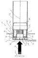
- the combustion chamber arrangement 10 comprises an essentially pot-like designed combustion chamber housing 12 with a substantially cylindrical or annular outer wall 14 and one, for example integrally designed and a combustion chamber 16 on one side axially - 12-delimiting with respect to a longitudinal center axis L of the combustion chamber housing Bottom wall 18.
- Integrally formed with the bottom wall can also have a combustion air inlet connection, which is likewise provided essentially in a ring Be 20, so in the then essentially annular bottom wall 18, a combustion air supply area 22 is formed, in which those only indicated schematically Combustion air blower 24 brought up and indicated by an arrow B. Combustion air can flow.
- combustion air inlet connection 20 which essentially also has an inner wall of the combustion chamber housing 12 so that a substantially annular Combustion chamber 16 is formed, several are distributed in the circumferential direction Combustion air inlet openings 26 are formed so that the through the Combustion air blower 24 initially supplied combustion air P flows towards the bottom wall 18 in the direction of the longitudinal axis L.
- the combustion air supply area 22 into the combustion air inlet connection 20 arrives and through the combustion air inlet openings 26 then flows essentially radially outwards and thus into the Combustion chamber 16 arrives.
- a porous evaporator medium 30 is provided on an inside 28 of the outer wall 14 of the combustion chamber housing 12.
- This porous Evaporator medium 30 is preferably designed to cover the entire Covering inside 28.
- Via a fuel line, not shown becomes liquid fuel from the outside through the outer wall 14 sprayed into the porous evaporator medium 30 so that it is below Capillary delivery effect distributed therein and towards the combustion chamber 16 lying surface of the porous evaporator medium 16 then evaporates.
- Combustion air P also introduced is a combustible or ignitable air / fuel mixture generated.
- glow ignition element can initiate the ignition so that when the ignition is off the combustion exhaust gases the open end region axially distant from the bottom wall 18 emerge from the combustion chamber 16 and in one in the direction of the longitudinal axis L enter the elongated flame tube 32 and there through a flame shield 35 flow through.
- limiting element 34 in the form of an annular disk is provided in the combustion chamber housing 12 . In the example shown, this is on the combustion air inlet connection 20 pushed on and rests on a shoulder 36 formed thereon. to fixed bracket, a locking ring can be provided. Is also one correspondingly tight fit between the limiting element 34 and the combustion air inlet connection possible.
- the limiting element 34 is positioned so that it is at a distance from the bottom wall 18, so that between the bottom wall 18 and this limiting element 34 a space 38 is formed. Through the limiting element 34 thus becomes the combustion chamber 16 provided in the combustion chamber housing 12 divided into two areas, namely the one already mentioned Gap and the other one on the other side of the delimitation element 34 still effective effective for combustion Area 40.
- the limiting element 34 takes over in the combustion chamber arrangement according to the invention 10 an aperture function so that through the foregoing mentioned division of the entire combustion chamber 16 in the for the combustion effective area 40 and the one not for combustion effective area or space 38 an insulation area to the bottom wall 18 is created.
- this space 38 is namely solely due to the fact that essentially no combustion air no combustion will take place in this area.
Landscapes
- Engineering & Computer Science (AREA)
- Chemical & Material Sciences (AREA)
- Combustion & Propulsion (AREA)
- Mechanical Engineering (AREA)
- General Engineering & Computer Science (AREA)
- Wick-Type Burners And Burners With Porous Materials (AREA)
Abstract
Description
Claims (8)
- Brennkammeranordnung, insbesondere für ein Fahrzeugheizgerät, umfassend ein Brennkammergehäuse (12) mit einer Außenwandung (14) und einer Bodenwandung (18), wobei in der Bodenwandung (18) ein Verbrennungsluftzuführbereich (22) zum Zuführen von Verbrennungsluft (P) in eine in dem Brennkammergehäuse (12) gebildete Brennkammer (16) vorgesehen ist, wobei in dem Brennkammergehäuse (12) ein Begrenzungselement (34) vorgesehen ist, das einen zur Verbrennung wirksamen Bereich (40) der Brennkammer (12) in Abstand zur Bodenwandung (18) begrenzt.
- Brennkammeranordnung nach Anspruch 1,
dadurch gekennzeichnet, dass zwischen dem Begrenzungselement (34) und der Bodenwandung (18) ein Zwischenraum (38) vorgesehen ist. - Brennkammeranordnung nach Anspruch 2,
dadurch gekennzeichnet, dass der Zwischenraum (38) in Verbindung mit dem zur Verbrennung wirksamen Bereich (40) der Brennkammer (16) steht. - Brennkammeranordnung nach einem der Ansprüche 1 bis 3,
dadurch gekennzeichnet, dass von der Bodenwandung (18) ein Verbrennungslufteintrittsabschnitt (20) ausgeht und dass das Begrenzungselement (34) an dem Verbrennungslufteintrittsabschnitt (20) getragen ist. - Brennkammeranordnung nach Anspruch 2,
dadurch gekennzeichnet, dass zwischen einem Außenumfangsbereich des Begrenzungselements (34) und der Außenwandung (12) des Brennkammergehäuses (12) wenigstens bereichsweise ein Abstand vorgesehen ist. - Brennkammeranordnung nach einem der Ansprüche 1 bis 5,
dadurch gekennzeichnet, dass an einer der Brennkammer (16) zugewandten Seite (28) der Außenwandung (14) des Brennkammergehäuses (12) ein poröses Verdampfermedium (30) vorgesehen ist. - Brennkammeranordnung nach Anspruch 5 und Anspruch 6,
dadurch gekennzeichnet, dass zwischen einem Außenumfangsbereich des Begrenzungselements (34) und dem porösen Verdampfermedium (30) wenigstens bereichsweise ein Abstand vorgesehen ist. - Heizgerät, insbesondere Fahrzeugheizgerät, umfassend eine Brennkammeranordnung (10) nach einem der vorangehenden Ansprüche und ein Verbrennungsluftgebläse (24), welches Verbrennungsluft (P) in Richtung auf die Bodenwandung (18) des Brennkammergehäuses (12) zu und durch den Verbrennungslufteintrittsbereich (22) desselben hindurch in die Brennkammer (16) fördert.
Applications Claiming Priority (2)
| Application Number | Priority Date | Filing Date | Title |
|---|---|---|---|
| DE10323899 | 2003-05-26 | ||
| DE2003123899 DE10323899B3 (de) | 2003-05-26 | 2003-05-26 | Brennkammeranordnung |
Publications (2)
| Publication Number | Publication Date |
|---|---|
| EP1482242A1 true EP1482242A1 (de) | 2004-12-01 |
| EP1482242B1 EP1482242B1 (de) | 2011-01-26 |
Family
ID=32748319
Family Applications (1)
| Application Number | Title | Priority Date | Filing Date |
|---|---|---|---|
| EP20040006109 Expired - Lifetime EP1482242B1 (de) | 2003-05-26 | 2004-03-15 | Brennkammeranordnung |
Country Status (2)
| Country | Link |
|---|---|
| EP (1) | EP1482242B1 (de) |
| DE (2) | DE10323899B3 (de) |
Families Citing this family (1)
| Publication number | Priority date | Publication date | Assignee | Title |
|---|---|---|---|---|
| DE102008028316B4 (de) * | 2008-06-13 | 2024-12-19 | Eberspächer Climate Control Systems GmbH | Brennkammerbaugruppe für einen Verdampferbrenner, insbesondere bei einem Fahrzeugheizgerät |
Citations (4)
| Publication number | Priority date | Publication date | Assignee | Title |
|---|---|---|---|---|
| US5197871A (en) | 1991-08-06 | 1993-03-30 | Mikuni Kogyo Kabushiki Kaisha | Vaporizing type burner |
| DE19507556A1 (de) | 1994-10-20 | 1996-04-25 | Eberspaecher J | Brenner für ein Fahrzeugheizgerät oder einen Partikelfilter-Regenerator |
| DE19717544A1 (de) | 1997-04-25 | 1998-10-29 | Eberspaecher J Gmbh & Co | Verdampferbrenner für ein Heizgerät oder eine thermische Regeneration eines Abgas-Partikelfilters |
| DE10130638A1 (de) * | 2001-06-26 | 2003-01-02 | Eberspaecher J Gmbh & Co | Verdampferbrenner |
Family Cites Families (2)
| Publication number | Priority date | Publication date | Assignee | Title |
|---|---|---|---|---|
| JP2520078B2 (ja) * | 1992-10-28 | 1996-07-31 | 株式会社ミクニアデック | 蒸発式バ―ナ |
| DE19548223B4 (de) * | 1995-08-16 | 2005-05-04 | J. Eberspächer GmbH & Co. KG | Verdampferbrenner |
-
2003
- 2003-05-26 DE DE2003123899 patent/DE10323899B3/de not_active Expired - Lifetime
-
2004
- 2004-03-15 DE DE200450012138 patent/DE502004012138D1/de not_active Expired - Lifetime
- 2004-03-15 EP EP20040006109 patent/EP1482242B1/de not_active Expired - Lifetime
Patent Citations (4)
| Publication number | Priority date | Publication date | Assignee | Title |
|---|---|---|---|---|
| US5197871A (en) | 1991-08-06 | 1993-03-30 | Mikuni Kogyo Kabushiki Kaisha | Vaporizing type burner |
| DE19507556A1 (de) | 1994-10-20 | 1996-04-25 | Eberspaecher J | Brenner für ein Fahrzeugheizgerät oder einen Partikelfilter-Regenerator |
| DE19717544A1 (de) | 1997-04-25 | 1998-10-29 | Eberspaecher J Gmbh & Co | Verdampferbrenner für ein Heizgerät oder eine thermische Regeneration eines Abgas-Partikelfilters |
| DE10130638A1 (de) * | 2001-06-26 | 2003-01-02 | Eberspaecher J Gmbh & Co | Verdampferbrenner |
Also Published As
| Publication number | Publication date |
|---|---|
| DE502004012138D1 (de) | 2011-03-10 |
| DE10323899B3 (de) | 2004-08-26 |
| EP1482242B1 (de) | 2011-01-26 |
Similar Documents
| Publication | Publication Date | Title |
|---|---|---|
| EP1860379B1 (de) | Verdampferbaugruppe, insbesondere für ein Fahrzeugheizgerät oder eine Reformeranordnung eines Brennstoffzellensystems | |
| DE19507556B4 (de) | Verfahren zum Starten eines Brenners für ein Fahrzeugheizgerät oder einen Partikelfilter-Regenerator | |
| EP1591154A1 (de) | Verdampferanordnung zur Erzeugung eines Kohlenwasserstoffdampf/Mischmaterial-Gemisches, insbesondere für eine Reformeranordnung eines Brennstoffzellensystems | |
| WO2001057446A1 (de) | Heizgerät, insbesondere motorunabhängige fahrzeugheizung | |
| EP3611431B1 (de) | Brennkammerbaugruppe für ein fahrzeugheizgerät | |
| DE102017107592B4 (de) | Flammen-Überwachungsanordnung für ein mit Brennstoff arbeitendes Heizgerät | |
| DE10160655C2 (de) | Brennkammerbaugruppe für ein Heizgerät | |
| EP1484552B1 (de) | Brennkammeranordnung für einen Verdampferbrenner, insbesondere für ein Fahrzeugheizgerät | |
| EP1363070B1 (de) | Verdampferbrenner und Verfahren zum Abtragen von Ablagerungen an einem Verdampferbrenner | |
| DE102014103815B4 (de) | Verdampferbrenner | |
| EP3534010B1 (de) | Verbrennungsluftgebläse | |
| EP1522788B1 (de) | Verdampferbrenner | |
| DE10323899B3 (de) | Brennkammeranordnung | |
| EP1464893B1 (de) | Brenneranordnung für ein Heizgerät und Heizgerät, insbesondere Fahrzeugheizgerät | |
| DE3509347C2 (de) | ||
| EP1927489B1 (de) | Fahrzeugheizgerät | |
| DE102011084868B4 (de) | Verdampferbrenner, insbesondere für ein Fahrzeugheizgerät | |
| DE10221495B4 (de) | Brenner für ein Heizgerät | |
| EP2012058A2 (de) | Fahrzeugheizgerät | |
| DE3726862A1 (de) | Kraftfahrzeugheizung | |
| EP1927488B1 (de) | Fahrzeugheizgerät | |
| EP3550151B1 (de) | Verbrennungsluftgebläse | |
| DE102008028316B4 (de) | Brennkammerbaugruppe für einen Verdampferbrenner, insbesondere bei einem Fahrzeugheizgerät | |
| EP1925477A2 (de) | Fahrzeugheizgerät | |
| DE10207953A1 (de) | Heizgerät, insbesondere für ein Fahrzeug |
Legal Events
| Date | Code | Title | Description |
|---|---|---|---|
| PUAI | Public reference made under article 153(3) epc to a published international application that has entered the european phase |
Free format text: ORIGINAL CODE: 0009012 |
|
| AK | Designated contracting states |
Kind code of ref document: A1 Designated state(s): AT BE BG CH CY CZ DE DK EE ES FI FR GB GR HU IE IT LI LU MC NL PL PT RO SE SI SK TR |
|
| AX | Request for extension of the european patent |
Extension state: AL LT LV MK |
|
| 17P | Request for examination filed |
Effective date: 20041112 |
|
| AKX | Designation fees paid |
Designated state(s): CZ DE GB PL SE |
|
| 17Q | First examination report despatched |
Effective date: 20100416 |
|
| GRAP | Despatch of communication of intention to grant a patent |
Free format text: ORIGINAL CODE: EPIDOSNIGR1 |
|
| GRAS | Grant fee paid |
Free format text: ORIGINAL CODE: EPIDOSNIGR3 |
|
| GRAA | (expected) grant |
Free format text: ORIGINAL CODE: 0009210 |
|
| AK | Designated contracting states |
Kind code of ref document: B1 Designated state(s): CZ DE GB PL SE |
|
| REG | Reference to a national code |
Ref country code: GB Ref legal event code: FG4D Free format text: NOT ENGLISH |
|
| REF | Corresponds to: |
Ref document number: 502004012138 Country of ref document: DE Date of ref document: 20110310 Kind code of ref document: P |
|
| REG | Reference to a national code |
Ref country code: DE Ref legal event code: R096 Ref document number: 502004012138 Country of ref document: DE Effective date: 20110310 |
|
| REG | Reference to a national code |
Ref country code: SE Ref legal event code: TRGR |
|
| PG25 | Lapsed in a contracting state [announced via postgrant information from national office to epo] |
Ref country code: PL Free format text: LAPSE BECAUSE OF FAILURE TO SUBMIT A TRANSLATION OF THE DESCRIPTION OR TO PAY THE FEE WITHIN THE PRESCRIBED TIME-LIMIT Effective date: 20110126 |
|
| REG | Reference to a national code |
Ref country code: SE Ref legal event code: EUG |
|
| PG25 | Lapsed in a contracting state [announced via postgrant information from national office to epo] |
Ref country code: CZ Free format text: LAPSE BECAUSE OF FAILURE TO SUBMIT A TRANSLATION OF THE DESCRIPTION OR TO PAY THE FEE WITHIN THE PRESCRIBED TIME-LIMIT Effective date: 20110126 |
|
| PLBE | No opposition filed within time limit |
Free format text: ORIGINAL CODE: 0009261 |
|
| STAA | Information on the status of an ep patent application or granted ep patent |
Free format text: STATUS: NO OPPOSITION FILED WITHIN TIME LIMIT |
|
| GBPC | Gb: european patent ceased through non-payment of renewal fee |
Effective date: 20110426 |
|
| 26N | No opposition filed |
Effective date: 20111027 |
|
| REG | Reference to a national code |
Ref country code: DE Ref legal event code: R097 Ref document number: 502004012138 Country of ref document: DE Effective date: 20111027 |
|
| PG25 | Lapsed in a contracting state [announced via postgrant information from national office to epo] |
Ref country code: GB Free format text: LAPSE BECAUSE OF NON-PAYMENT OF DUE FEES Effective date: 20110426 |
|
| PG25 | Lapsed in a contracting state [announced via postgrant information from national office to epo] |
Ref country code: SE Free format text: LAPSE BECAUSE OF NON-PAYMENT OF DUE FEES Effective date: 20110316 |
|
| REG | Reference to a national code |
Ref country code: DE Ref legal event code: R082 Ref document number: 502004012138 Country of ref document: DE Representative=s name: WEICKMANN & WEICKMANN, DE |
|
| REG | Reference to a national code |
Ref country code: DE Ref legal event code: R082 Ref document number: 502004012138 Country of ref document: DE Representative=s name: WEICKMANN & WEICKMANN, DE Effective date: 20130607 Ref country code: DE Ref legal event code: R081 Ref document number: 502004012138 Country of ref document: DE Owner name: EBERSPAECHER CLIMATE CONTROL SYSTEMS GMBH & CO, DE Free format text: FORMER OWNER: J. EBERSPAECHER GMBH & CO. KG, 73730 ESSLINGEN, DE Effective date: 20130607 Ref country code: DE Ref legal event code: R082 Ref document number: 502004012138 Country of ref document: DE Representative=s name: RUTTENSPERGER LACHNIT TROSSIN GOMOLL PATENT- U, DE Effective date: 20130607 Ref country code: DE Ref legal event code: R082 Ref document number: 502004012138 Country of ref document: DE Representative=s name: RUTTENSPERGER LACHNIT TROSSIN GOMOLL, PATENT- , DE Effective date: 20130607 |
|
| REG | Reference to a national code |
Ref country code: DE Ref legal event code: R082 Ref document number: 502004012138 Country of ref document: DE Representative=s name: RUTTENSPERGER LACHNIT TROSSIN GOMOLL PATENT- U, DE Ref country code: DE Ref legal event code: R082 Ref document number: 502004012138 Country of ref document: DE Representative=s name: RUTTENSPERGER LACHNIT TROSSIN GOMOLL, PATENT- , DE |
|
| REG | Reference to a national code |
Ref country code: DE Ref legal event code: R082 Ref document number: 502004012138 Country of ref document: DE Representative=s name: RUTTENSPERGER LACHNIT TROSSIN GOMOLL, PATENT- , DE Ref country code: DE Ref legal event code: R081 Ref document number: 502004012138 Country of ref document: DE Owner name: EBERSPAECHER CLIMATE CONTROL SYSTEMS GMBH, DE Free format text: FORMER OWNER: EBERSPAECHER CLIMATE CONTROL SYSTEMS GMBH & CO. KG, 73730 ESSLINGEN, DE |
|
| PGFP | Annual fee paid to national office [announced via postgrant information from national office to epo] |
Ref country code: DE Payment date: 20230331 Year of fee payment: 20 |
|
| REG | Reference to a national code |
Ref country code: DE Ref legal event code: R071 Ref document number: 502004012138 Country of ref document: DE |