EP1482222A1 - Robinet à voies multiples pour un dispositif de refroidissement/chauffage d'un véhicule - Google Patents
Robinet à voies multiples pour un dispositif de refroidissement/chauffage d'un véhicule Download PDFInfo
- Publication number
- EP1482222A1 EP1482222A1 EP20040012333 EP04012333A EP1482222A1 EP 1482222 A1 EP1482222 A1 EP 1482222A1 EP 20040012333 EP20040012333 EP 20040012333 EP 04012333 A EP04012333 A EP 04012333A EP 1482222 A1 EP1482222 A1 EP 1482222A1
- Authority
- EP
- European Patent Office
- Prior art keywords
- valve
- connection
- main valve
- fluid line
- heat exchanger
- Prior art date
- Legal status (The legal status is an assumption and is not a legal conclusion. Google has not performed a legal analysis and makes no representation as to the accuracy of the status listed.)
- Granted
Links
Images


Classifications
-
- B—PERFORMING OPERATIONS; TRANSPORTING
- B60—VEHICLES IN GENERAL
- B60H—ARRANGEMENTS OF HEATING, COOLING, VENTILATING OR OTHER AIR-TREATING DEVICES SPECIALLY ADAPTED FOR PASSENGER OR GOODS SPACES OF VEHICLES
- B60H1/00—Heating, cooling or ventilating [HVAC] devices
- B60H1/00642—Control systems or circuits; Control members or indication devices for heating, cooling or ventilating devices
- B60H1/00978—Control systems or circuits characterised by failure of detection or safety means; Diagnostic methods
-
- B—PERFORMING OPERATIONS; TRANSPORTING
- B60—VEHICLES IN GENERAL
- B60H—ARRANGEMENTS OF HEATING, COOLING, VENTILATING OR OTHER AIR-TREATING DEVICES SPECIALLY ADAPTED FOR PASSENGER OR GOODS SPACES OF VEHICLES
- B60H1/00—Heating, cooling or ventilating [HVAC] devices
- B60H1/00485—Valves for air-conditioning devices, e.g. thermostatic valves
-
- B—PERFORMING OPERATIONS; TRANSPORTING
- B60—VEHICLES IN GENERAL
- B60H—ARRANGEMENTS OF HEATING, COOLING, VENTILATING OR OTHER AIR-TREATING DEVICES SPECIALLY ADAPTED FOR PASSENGER OR GOODS SPACES OF VEHICLES
- B60H1/00—Heating, cooling or ventilating [HVAC] devices
- B60H1/02—Heating, cooling or ventilating [HVAC] devices the heat being derived from the propulsion plant
- B60H1/04—Heating, cooling or ventilating [HVAC] devices the heat being derived from the propulsion plant from cooling liquid of the plant
- B60H1/08—Heating, cooling or ventilating [HVAC] devices the heat being derived from the propulsion plant from cooling liquid of the plant from other radiator than main radiator
-
- F—MECHANICAL ENGINEERING; LIGHTING; HEATING; WEAPONS; BLASTING
- F16—ENGINEERING ELEMENTS AND UNITS; GENERAL MEASURES FOR PRODUCING AND MAINTAINING EFFECTIVE FUNCTIONING OF MACHINES OR INSTALLATIONS; THERMAL INSULATION IN GENERAL
- F16K—VALVES; TAPS; COCKS; ACTUATING-FLOATS; DEVICES FOR VENTING OR AERATING
- F16K11/00—Multiple-way valves, e.g. mixing valves; Pipe fittings incorporating such valves
- F16K11/02—Multiple-way valves, e.g. mixing valves; Pipe fittings incorporating such valves with all movable sealing faces moving as one unit
- F16K11/08—Multiple-way valves, e.g. mixing valves; Pipe fittings incorporating such valves with all movable sealing faces moving as one unit comprising only taps or cocks
- F16K11/085—Multiple-way valves, e.g. mixing valves; Pipe fittings incorporating such valves with all movable sealing faces moving as one unit comprising only taps or cocks with cylindrical plug
- F16K11/0856—Multiple-way valves, e.g. mixing valves; Pipe fittings incorporating such valves with all movable sealing faces moving as one unit comprising only taps or cocks with cylindrical plug having all the connecting conduits situated in more than one plane perpendicular to the axis of the plug
-
- Y—GENERAL TAGGING OF NEW TECHNOLOGICAL DEVELOPMENTS; GENERAL TAGGING OF CROSS-SECTIONAL TECHNOLOGIES SPANNING OVER SEVERAL SECTIONS OF THE IPC; TECHNICAL SUBJECTS COVERED BY FORMER USPC CROSS-REFERENCE ART COLLECTIONS [XRACs] AND DIGESTS
- Y10—TECHNICAL SUBJECTS COVERED BY FORMER USPC
- Y10T—TECHNICAL SUBJECTS COVERED BY FORMER US CLASSIFICATION
- Y10T137/00—Fluid handling
- Y10T137/8593—Systems
- Y10T137/877—With flow control means for branched passages
- Y10T137/87909—Containing rotary valve
Definitions
- the present invention relates to a multi-way valve comprising a Valve housing arrangement in which a valve chamber is formed at least three main valve connections leading to the valve chamber Main valve element, which can be optionally interrupted and released the connection of the main valve connections with the valve chamber in one A plurality of valve member positions can be brought, with each valve member position the main valve gear at least two of the main valve ports stand in connection with the valve chamber.
- Such a multi-way valve is known for example from DE 198 16 522 A1 known.
- This known valve is in terms of its principle Structure and its operation shown in Figures 1 to 4 and will be described below with reference to these figures.
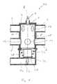
- valve body in which a valve chamber 8 is formed.
- valve connections 3, 4, 5 and 6 open into the cylindrical peripheral wall of the valve body 2 and are therefore always in connection with the valve chamber 8. It can be seen that the four valve connections 3, 4, 5, 6 each one another are arranged in pairs opposite each other, so that in a first or in the upper level in FIG.
- valve connection 5 directly under the valve port 3 of the other pair of Valve connections is located directly below the valve connection 6 the valve port 4 of the other pair of valve ports.
- valve body 12 there is essentially one adapted to its contour cylindrical or circular-cylindrical valve member 1 intended. This is not in the area of a drive shaft 7 by one shown drive motor for rotation about the axis A.
- the valve member 1 In Assignment to each pair of valve connections 3 and 4 or 5 and 6 the valve member 1 has openings 10, 11, 12 and 13, 14, 15, respectively on. These two groups of openings 10, 11, 12 and 13, 14, 15 are as well as the two pairs of valve connections 3, 4, and 5, 6, in the two levels already mentioned previously, so that by rotating the valve member 1 by means of the openings 10, 11, 12, 13, 14, 15 the connection of the various valve connections 3, 4, 5, 6 with the valve chamber 8 can be interrupted, released or partially released. It can be seen above all in FIGS.
- the selection of the circumferential extensions is such that when the valve member 1 in a is brought from several main valve positions, which main valve positions in each case by turning the valve member through 45 ° from a previous one Main valve position can be achieved with less Circumferentially extending openings 11, 12 and 14, 15 either with one of the assigned valve connections 3, 4 or 5, 6 completely aligned or completely not aligned and those with longer ones Circumferential extension formed openings 10 and 13 at two immediately adjacent main valve positions with one of each Valve connections 3, 4 or 5, 6 are aligned and thus release them.
- valve member 1 If the valve member 1 is turned through 45 ° to a third main valve position, so is now the opening 10 with a longer circumferential distance top group of openings out of alignment with the valve port 3 moved out while the opening 12 the connection between the valve port 4 and the valve chamber 8 releases. In the lower group of openings is now the opening 13 with a longer one Circumference in alignment with the valve port 5 while the valve port 6 is not aligned with any opening. Then it is that Line connection between the valve connection 4 and the valve connection 5 manufactured via the valve chamber 8. The valve member 1 around Turned 45 ° further, a fourth main valve position is reached. In these are also the openings 13 of the lower group of openings in alignment with the valve connection 5.
- valve connection 6 is now in alignment with the opening 14 so that the two valve connections 6 and 5 via the valve chamber 8 now in connection with each other stand. There is now none of the top group of openings aligned with one of the valve connections 3 or 4, so that the in the Fig. 2 on the far right recognizable state is reached.
- valve connection 6 is now partially aligned with the valve connection 6, so that in this intermediate state a connection between the valve connections 3, 4 and 6 is present via the valve chamber 8.
- a connection via the openings 10 and 12 made between the valve ports 3 and 4 and the valve chamber 8 while via the openings 13 and 15 also the valve connections 5 and 6 are in connection with the valve chamber 8.
- the valve member is in an intermediate position brought between the main valve positions 3 and 4, so remains continue to complete valve port 3, while additionally now
- the valve connection 6 is connected via the opening 14 and thus the valve connections 4, 5 and 6 with each other via the valve chamber 8 in Connect.
- valve connections then released for fluid communication are formed by the sum of those in the intermediate valve position on both sides main valve positions released valve connections.
- the one valve position is basically released Valve connections with a larger cross-section are released while released in the main valve position which is further away Valve connections are throttled more. That way a defined one even if more than two valve connections are enabled Flow control achieved through defined generation of throttling effects become.
- This type of multi-way valve is used in particular in vehicle cooling / heating systems, in which the coolant circuit of the drive unit, generally an internal combustion engine, optionally directed in this way should be that, for example, in a cold start phase, the cooling medium circulated only through the power pack and not in contact with any Heat exchanger arrangement can get that at comparatively high coolant temperature this between the drive unit and circulate a heat exchanger arrangement, for example a cooler can that at a comparatively high temperature of the cooling medium and Heating requirement in the vehicle alternatively or in addition to switching on the Cooler another heat exchanger arrangement, for example a heating heat exchanger, can be switched into the fluid circuit, or that in the start-up phase, i.e. with a comparatively cold cooling medium and when there is a need for heating in the vehicle, a fluid circuit between the drive unit and the heating heat exchanger is built up during the Cooler is disconnected from this circuit.
- a heat exchanger arrangement for example a cooler can that at a comparatively high temperature of the cooling medium and Heating requirement in the vehicle alternative
- a problem with such a valve can occur if it is suffers from a defect in one of its valve positions and is no longer adjusted can be.
- the valve cannot be switched after this start phase has ended there is a risk of the cooling medium overheating and the drive unit.
- a multi-way valve comprising a valve housing assembly in which a valve chamber is designed, at least three main valve connections leading to the valve chamber, a main valve member which can be interrupted optionally and releasing the connection of the main valve ports to the valve chamber can be brought into a plurality of valve member positions, wherein in each valve organ position of the main valve gear at least two of the Main valve connections are in connection with the valve chamber, which is further characterized by at least one to the valve chamber leading secondary valve connection and an associated and for Interrupting and releasing the connection of the secondary valve connection auxiliary valve element adjustable with the valve chamber.
- the secondary valve member depending on a temperature in the range Valve chamber between an open position and a release position is adjustable.
- the Secondary valve member has an actuator that is induced by thermally Dimension change the auxiliary valve member between the interrupt position and the release position.
- this valve has four main valve connections.
- the second heat exchanger arrangement is a vehicle heating heat exchanger includes that of the third fluid line or the fourth fluid line a heater for heating flowing therein Fluid is assigned, and that a valve arrangement is provided by which optionally the third fluid line and the fourth fluid line from third main valve connection and uncouplable from the fourth main valve connection is to ensure fluid circulation between the second heat exchanger assembly and to generate the heater, or the third fluid line and the fourth fluid line for connecting the second heat exchanger arrangement a third main valve port and the fourth main valve port can be released.
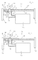
- This multi-way valve 36 is basically or in essential areas structured so like the multi-way valve known from DE 198 16 522 A1, which previously described in detail with reference to FIGS. 1 to 4 has been. Insofar as there is agreement, reference is hereby made to the preceding statements and also the disclosure content of the Taken from DE 198 16 522 A1.
- Valve body 2 also shows the cylindrical or circular-cylindrical design Valve body 2, in which the valve openings 3, 4, 5 and 6, which now form so-called main valve openings, each in pairs (3rd and 4 or 5 and 6) lying opposite each other in two in the direction of Longitudinal axis of the valve body 2 offset levels open.
- Valve body 2 is again the one with the outer peripheral wall of the valve body 2 corresponding contour or shape formed valve member 1 now provided as the main valve member.
- about the pen or the Shaft 7 can this valve member 1 by, for example, in Fig. 6 recognizable drive motor 38, for example stepper motor, under the Control of a control unit 40 driven to rotate about the axis A.
- valve housing 34 leads or is provided therein a secondary valve opening 32, which is basically also in connection with the Valve chamber 8 is or is bringabr.
- a is in the housing 34
- Valve opening 30 is provided, on which a secondary valve member 28 below the bias of a bias spring 26 is seated.
- the state shown is the connection between the secondary valve connection 32 and the valve chamber 8 by the in its closed position biased secondary valve member 28 completed.
- the bias spring 26 for example, on a Can support flange area of the valve body 2, which in the connection area of the valve body 2 is formed with the housing 34.
- the auxiliary valve member 28 is associated with an actuator 22 which on Secondary valve member 28 supported on the one hand and on the housing 34 on the other hand is.
- This control element for example on a floor area of the pot-shaped secondary valve member 28 can be supported, comprises a piston / piston rod element attached to a pot-like Bottom area of the secondary valve member 28 with intermediate storage Material with a comparatively large thermal expansion coefficient, for example wax, is supported and elsewhere, as in FIG. 5 recognizable, is supported on the housing 34. If this control element 22 is heated, it expands and acts on the auxiliary valve member 28 counter to the biasing action of the spring 26, so that with sufficient Acting action, the valve member 28 opens the opening 30 or partially releases, depending on the extent of warming and expansion of the Control element 22.
- the control status is thus of the auxiliary valve member 28 is dependent on the temperature in the Area of the multi-way valve 36, in particular in the area of the valve chamber 8 of the same prevails.
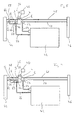
- This characteristic can be how will be used in the following, depending on the temperature unlock or interrupt an additional flow path in order to thus an increased operational reliability of such a multi-way valve equipped cooling / heating system, for example in one Motor vehicle to provide. This is particularly mentioned below Described with reference to Figures 6 to 10, which different operating states one equipped with the multi-way valve 36 shown in FIG. 5 Show cooling / heating system 24.
- the cooling / heating system 24 shown in FIG. 6 initially shows what is essential System area designated by 42 and for example as an internal combustion engine designed drive unit. There are also a radiator heat exchanger 44 and a heating heat exchanger 46 are provided. In the radiator heat exchanger 44, the circulating cooling medium, for example Release water and heat to the environment. In the heating heat exchanger 46 can transfer heat to air to be introduced into a vehicle interior become. Between the main valve connection 4 and the heating heat exchanger 46 a line 48 is provided. Likewise, between the main valve connection 6 and the heating heat exchanger 46 a Line 50 is provided, one of which in the region of a branch 52 Line 54 branches off to the drive unit 42. So that's also Drive unit 42 in connection with the main valve connection 6.
- a line 58 is provided, as well as between the main valve connection 5 and the cooler heat exchanger 44 a line 62 is provided is.
- a line 56 branches from this line 62 to the drive unit 42 so that this is also in connection with the main valve connection 5.
- the secondary valve connection is through a branch 66 and a line 60 32 in connection with the line 58 and thus also the Main valve connection 3 or the radiator heat exchanger 4.
- FIG. 6 is in a cold start state is, which is shortly after starting the drive unit 42 this and the circulating cooling medium still a temperature have well below the desired operating temperature.
- the multi-way valve 36 is now numbered in the fourth shown in Figures 1 to 4d) Main valve position brought in which the two main valve connections 5 and 6 are connected. Because the cooling medium is comparatively has low temperature, the sub-valve member 28th shut off the auxiliary valve port 32 so that, as by dashed lines Arrows indicated, the cooling medium via lines 56 and 54 and Circulate main valve connections 5 and 6 through the drive unit 42 can, here of course a corresponding circulation pump can be provided, for example, in the area of the drive unit 42.
- the multi-way valve 36 now becomes brought into the third main valve position, in which a connection between the main valve connections 5 and 4 is available.
- FIGS. 1 to 4 show that this is the first main valve position shown in section a) (FIG. 8).
- Multi-way valve 36 in that shown in section b) of Figures 1 to 4 brought second main valve position, in which a connection between the main valve ports 3 and 6 is present while the main valve ports 5 and 4 are not connected to the valve chamber 8.
- the heating medium then flows via lines 56 and 62 to the cooler heat exchanger 44 and from this via line 58, the main valve connection 3, the valve chamber 8, the main valve port 6 and the Line 54 back to the drive unit 42 (Fig. 9).
- Valve chamber 8 also connects between the main valve opening 5 and the auxiliary valve opening 32, so that in addition line 60, line 58 from junction 66, the radiator heat exchanger 44 and line 62 unlocked a circulation section which is the by flowing through the cooler heat exchanger 44th allows.
- a circulation connection between the drive unit 42 and the radiator heat exchanger 44, so that at least part of the drive unit 52 leaving line 56 Cooling medium circulates through the radiator heat exchanger 44 and is thus cooled.
- This proportion can increase with increasing temperature still be enlarged that the actuator 22 due to the the secondary valve member 28 then also occurs if there is further expansion moved further away from the opening 30 and thus through the secondary valve member 28 throttle effect generated is further reduced.
- Cooling medium through this inclusion of the cooler heat exchanger 44 in the circuit is sufficiently cooled again, so will the control element 22 cool down and contract, which means that the Secondary valve connection 32, for example, completely from the valve chamber again 8 can be disconnected.
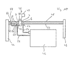
- FIG. 11 An alternative embodiment of a cooling / heating system according to the invention 24 is shown in FIG. 11.
- This system is basically from the same structure as previously with reference to FIGS. 6 to 10 described, but additionally has as a parking heater or possibly also Effective heater 70 with a multi-function pump 72.
- the heater 70 may be of conventional construction and a heat exchanger arrangement 74 include, in which heating, which in a Burner area 76 is generated, are transferred to the cooling medium can, which flows in line 48.
- the pump 72 can be configured in this way be that they also have the function of an optionally switchable Valve can meet.
- the structure is such that both the line 48, as well as the line 50 each in two line sections 48 'and 48 " or 50 'and 50 "can be divided.
- the line section 48' lies between the main valve port 4 and the pump 72, during the Line section 48 "between the pump 72 and the heating heat exchanger 46 lies and also has the heater 70.
- this operation is synchronous possible by appropriate control of the multi-way valve 36 also continue to operate the remaining system area, for example in the operating state shown in FIG. 6 or in FIG. 9.
- the pump 72 can e.g. coupled with the control of the multi-way valve 36 can be switched or the flow path switch so that the line sections 48 'and 48 "in connection stand, as well as the line sections 50 'and 50 ", so that by corresponding parallel control of the multi-way valve 36 now the Heater 70 and also the pump 72 in the remaining system area are switched on and, for example, when operating in the manner shown in FIG. 8
- Operating state or the operating state shown in Fig. 7 additionally help to transfer heat to the heating medium and thus for example, in the cold start mode, the drive unit 42 and the heating medium warm up faster.
- an intermediate valve position can also be taken between the states b) and c) of Figures 1 to 4.
- an intermediate valve position can also be taken between the states b) and c) of Figures 1 to 4.
Applications Claiming Priority (2)
| Application Number | Priority Date | Filing Date | Title |
|---|---|---|---|
| DE2003123900 DE10323900A1 (de) | 2003-05-26 | 2003-05-26 | Mehrwegeventil für ein Fahrzeug-Kühl/Heiz-System |
| DE10323900 | 2003-05-26 |
Publications (2)
| Publication Number | Publication Date |
|---|---|
| EP1482222A1 true EP1482222A1 (fr) | 2004-12-01 |
| EP1482222B1 EP1482222B1 (fr) | 2009-09-23 |
Family
ID=33103594
Family Applications (1)
| Application Number | Title | Priority Date | Filing Date |
|---|---|---|---|
| EP20040012333 Active EP1482222B1 (fr) | 2003-05-26 | 2004-05-25 | Robinet à voies multiples pour un dispositif de refroidissement/chauffage d'un véhicule |
Country Status (3)
| Country | Link |
|---|---|
| US (1) | US7165513B2 (fr) |
| EP (1) | EP1482222B1 (fr) |
| DE (2) | DE10323900A1 (fr) |
Cited By (5)
| Publication number | Priority date | Publication date | Assignee | Title |
|---|---|---|---|---|
| FR2923896A1 (fr) * | 2007-11-16 | 2009-05-22 | Anjos Soc Par Actions Simplifi | Organe de repartition d'air et dispositif de ventilation d'un local comprenant un tel organe |
| FR3040202A1 (fr) * | 2015-08-17 | 2017-02-24 | Peugeot Citroen Automobiles Sa | Electrovanne de commande comportant un cylindre rotatif commandant deux circuits |
| EP3159644A1 (fr) * | 2015-10-23 | 2017-04-26 | Viessmann Werke GmbH & Co. KG | Dispositif de transfert de chaleur |
| GB2600167A (en) * | 2020-10-26 | 2022-04-27 | Aalberts Integrated Piping Systems Ltd | Plumbing fitting |
| WO2022184915A1 (fr) * | 2021-03-05 | 2022-09-09 | Mack & Schneider Gmbh | Dispositif de soupape |
Families Citing this family (36)
| Publication number | Priority date | Publication date | Assignee | Title |
|---|---|---|---|---|
| FR2827359B1 (fr) * | 2001-07-11 | 2004-11-05 | Valeo Thermique Moteur Sa | Vanne de commande pour un circuit de refroidissement d'un moteur thermique de vehicule automobile |
| DE102006011835B4 (de) * | 2006-03-15 | 2017-08-24 | Mahle International Gmbh | Ventileinrichtung |
| DE102006033315A1 (de) | 2006-07-17 | 2008-01-24 | Behr Gmbh & Co. Kg | Ventil zur Steuerung eines Kühlmittelstroms für einen Heizkörper eines Kraftfahrzeuges, System mit zumindest einem Ventil |
| DE102006039480A1 (de) * | 2006-08-23 | 2008-03-06 | J. Eberspächer GmbH & Co. KG | Mehrwegeventil, insbesondere für ein Fahrzeug-Heiz/Kühl-System |
| DE102007048297A1 (de) * | 2007-10-08 | 2009-04-09 | Behr Gmbh & Co. Kg | Ventilvorrichtung zur Regelung eines rückgeführten gasförmigen Fluids, Wärmetauscher, Verfahren zur Regelung einer Ventilvorrichtung und/oder zur Regelung eines Wärmetauschers |
| US8066198B2 (en) * | 2009-01-16 | 2011-11-29 | Dana Canada Corporation | Valve apparatus for regulating a heat exchange liquid |
| US8978992B2 (en) * | 2009-09-14 | 2015-03-17 | Jiffy-Tite Company, Inc. | Cooler bypass apparatus and installation kit |
| WO2013126374A1 (fr) * | 2012-02-20 | 2013-08-29 | Cooper-Standard Automotive Inc. | Soupape à sécurité intégrée de dérivation de moteur à cire |
| US9897217B2 (en) | 2013-05-17 | 2018-02-20 | Magna Powertrain Inc. | Low-drag sealing method for thermal management valve |
| DE102014212546B4 (de) * | 2013-07-04 | 2017-10-12 | Ford Global Technologies, Llc | Flüssigkeitsgekühlte Brennkraftmaschine und Verfahren zum Betreiben einer derartigen Brennkraftmaschine |
| JP6254402B2 (ja) * | 2013-09-19 | 2017-12-27 | 日立オートモティブシステムズ株式会社 | 流量制御弁 |
| DE102013221574A1 (de) | 2013-10-23 | 2015-04-23 | Behr Thermot-Tronik Gmbh | Thermostatventil |
| JP6351352B2 (ja) * | 2014-04-30 | 2018-07-04 | 株式会社不二工機 | 流路切換弁 |
| KR101575338B1 (ko) * | 2014-07-08 | 2015-12-07 | 현대자동차 주식회사 | 엔진의 냉각수 제어밸브 |
| DE102014014964B4 (de) * | 2014-10-14 | 2016-10-20 | Henzel Formenbau Gmbh | Mehrwegeventil zur Steuerung von Flüssigkeitskreisen |
| DE102015201242B4 (de) * | 2015-01-26 | 2022-02-10 | Ford Global Technologies, Llc | Regelmittel zur Steuerung der Kühlmittelströme eines Split-Kühlsystems |
| DE102015201240B4 (de) * | 2015-01-26 | 2022-01-27 | Ford Global Technologies, Llc | Split-Kühlsystem sowie Brennkraftmaschine mit einem Split-Kühlsystem und entsprechend ausgestattetes Fahrzeug |
| US10337389B2 (en) | 2015-01-26 | 2019-07-02 | Ford Global Technologies, Llc | Control means for controlling the coolant flows of a split cooling system |
| WO2016182536A1 (fr) * | 2015-05-08 | 2016-11-17 | Volvo Truck Corporation | Vanne à trois voies |
| DE102015107926A1 (de) | 2015-05-20 | 2016-11-24 | Volkswagen Aktiengesellschaft | Brennkraftmaschine und Kraftfahrzeug |
| JP6459787B2 (ja) * | 2015-06-11 | 2019-01-30 | 株式会社デンソー | バルブ装置および流体制御装置 |
| JP6330748B2 (ja) * | 2015-07-29 | 2018-05-30 | トヨタ自動車株式会社 | 内燃機関の冷却装置 |
| JP6330768B2 (ja) * | 2015-09-16 | 2018-05-30 | トヨタ自動車株式会社 | エンジン冷却装置 |
| JP6493146B2 (ja) * | 2015-10-19 | 2019-04-03 | 株式会社デンソー | 弁制御装置 |
| EP3910261A1 (fr) | 2016-03-30 | 2021-11-17 | Marine Canada Acquisition Inc. | Appareil de chauffage de véhicule et commandes associées |
| SE541222C2 (en) * | 2016-05-16 | 2019-05-07 | Scania Cv Ab | A multi-valve and a multi-valve device for a cooling system |
| JP6846076B2 (ja) * | 2016-09-21 | 2021-03-24 | 日立Astemo株式会社 | 流量制御弁および冷却システム |
| JP6772991B2 (ja) * | 2016-09-27 | 2020-10-21 | 株式会社デンソー | 弁装置および冷却システム |
| US11092982B2 (en) * | 2018-07-23 | 2021-08-17 | Schaeffler Technologies AG & Co. KG | Temperature sensor for coolant control valve |
| KR20200045727A (ko) * | 2018-10-23 | 2020-05-06 | 현대자동차주식회사 | 차량용 히트펌프 시스템 |
| DE102019111829B4 (de) * | 2019-05-07 | 2022-12-29 | Deutsches Zentrum für Luft- und Raumfahrt e.V. | Regelventil zur Regelung eines Kühlmittelstroms in einem Kühlsystem |
| CN110529628B (zh) * | 2019-07-23 | 2024-04-02 | 上海蔚来汽车有限公司 | 一种多通阀、热管理系统及电动汽车 |
| DE102020201190A1 (de) * | 2019-10-14 | 2021-04-15 | Vitesco Technologies GmbH | Fluidventil |
| KR20220033184A (ko) * | 2020-09-09 | 2022-03-16 | 현대자동차주식회사 | 다유로 냉각수 밸브 |
| AT524293A1 (de) * | 2020-10-06 | 2022-04-15 | Avl List Gmbh | Ventileinheit für ein Konditioniersystem eines Prüfstands |
| US11885407B1 (en) * | 2022-07-15 | 2024-01-30 | Textron Innovations Inc. | Fluid scavenge system |
Citations (3)
| Publication number | Priority date | Publication date | Assignee | Title |
|---|---|---|---|---|
| US2277814A (en) * | 1940-04-08 | 1942-03-31 | Noblitt Sparks Ind Inc | Automobile heating system |
| FR2276957A1 (fr) * | 1974-07-03 | 1976-01-30 | Millet Jean | Perfectionnements aux robinets thermostatiques pour la commande des appareils de chauffage des vehicules automobiles |
| DE19816522A1 (de) | 1998-04-14 | 1999-10-28 | Eberspaecher J Gmbh & Co | Mehrwegeventil mit insbesondere der Verwendung in einer Kreislauf-Heizleitung mit zwei im Nebenschluß angeschlossenen Wärmetauschern |
Family Cites Families (2)
| Publication number | Priority date | Publication date | Assignee | Title |
|---|---|---|---|---|
| DE10042496A1 (de) * | 2000-08-30 | 2002-03-14 | Volkswagen Ag | Brennkraftmaschine mit Flüssigkeitskühlung und einer Kühlmittelzusatzheizung sowie Arbeitsverfahren einer solchen Flüssigkeitskühlung |
| DE10155386A1 (de) * | 2001-11-10 | 2003-05-22 | Bosch Gmbh Robert | Ventil mit Notfunktion |
-
2003
- 2003-05-26 DE DE2003123900 patent/DE10323900A1/de not_active Ceased
-
2004
- 2004-05-11 US US10/842,808 patent/US7165513B2/en not_active Expired - Fee Related
- 2004-05-25 DE DE200450010094 patent/DE502004010094D1/de active Active
- 2004-05-25 EP EP20040012333 patent/EP1482222B1/fr active Active
Patent Citations (3)
| Publication number | Priority date | Publication date | Assignee | Title |
|---|---|---|---|---|
| US2277814A (en) * | 1940-04-08 | 1942-03-31 | Noblitt Sparks Ind Inc | Automobile heating system |
| FR2276957A1 (fr) * | 1974-07-03 | 1976-01-30 | Millet Jean | Perfectionnements aux robinets thermostatiques pour la commande des appareils de chauffage des vehicules automobiles |
| DE19816522A1 (de) | 1998-04-14 | 1999-10-28 | Eberspaecher J Gmbh & Co | Mehrwegeventil mit insbesondere der Verwendung in einer Kreislauf-Heizleitung mit zwei im Nebenschluß angeschlossenen Wärmetauschern |
Cited By (6)
| Publication number | Priority date | Publication date | Assignee | Title |
|---|---|---|---|---|
| FR2923896A1 (fr) * | 2007-11-16 | 2009-05-22 | Anjos Soc Par Actions Simplifi | Organe de repartition d'air et dispositif de ventilation d'un local comprenant un tel organe |
| FR3040202A1 (fr) * | 2015-08-17 | 2017-02-24 | Peugeot Citroen Automobiles Sa | Electrovanne de commande comportant un cylindre rotatif commandant deux circuits |
| EP3159644A1 (fr) * | 2015-10-23 | 2017-04-26 | Viessmann Werke GmbH & Co. KG | Dispositif de transfert de chaleur |
| GB2600167A (en) * | 2020-10-26 | 2022-04-27 | Aalberts Integrated Piping Systems Ltd | Plumbing fitting |
| GB2600167B (en) * | 2020-10-26 | 2023-06-14 | Aalberts Integrated Piping Systems Ltd | Plumbing fitting |
| WO2022184915A1 (fr) * | 2021-03-05 | 2022-09-09 | Mack & Schneider Gmbh | Dispositif de soupape |
Also Published As
| Publication number | Publication date |
|---|---|
| US20040238159A1 (en) | 2004-12-02 |
| DE502004010094D1 (de) | 2009-11-05 |
| US7165513B2 (en) | 2007-01-23 |
| DE10323900A1 (de) | 2005-01-05 |
| EP1482222B1 (fr) | 2009-09-23 |
Similar Documents
| Publication | Publication Date | Title |
|---|---|---|
| EP1482222B1 (fr) | Robinet à voies multiples pour un dispositif de refroidissement/chauffage d'un véhicule | |
| DE3440504C2 (fr) | ||
| DE102013219953B4 (de) | Wärmetauscher für ein Fahrzeug | |
| DE102012113111B4 (de) | Wärmetauscher für ein Fahrzeug | |
| DE60223835T2 (de) | System zur Steuerung der von einem Verbrennungsmotor eines Kraftfahrzeugs entwickelten Wärmeenergie | |
| DE19809123B4 (de) | Wasserpumpe für den Kühlkreislauf einer Brennkraftmaschine | |
| EP2608973B1 (fr) | Dispositif de chauffage et de refroidissement et module de chauffage / de refroidissement pour un dispositif de chauffage / de refroidissement | |
| DE3635425C2 (fr) | ||
| DE102014106725B4 (de) | Kühlsystem für einen Antriebsstrang mit Motorwärmetauscher und Getriebewärmetauscher | |
| WO2004046516A1 (fr) | Soupape thermostatique destinee a un systeme de refroidissement d'un moteur a combustion interne | |
| WO2005111392A1 (fr) | Systeme de refroidissement pour un vehicule | |
| DE10161851A1 (de) | Kühlkreislauf einer flüssigkeitsgekühlten Brennkraftmaschine | |
| DE102006055536A1 (de) | Drehschieber mit mehreren Querschnittsverstellgliedern | |
| DE102013114464A1 (de) | Wärmetauscher für fahrzeug | |
| DE3208199C2 (de) | Flüssigkeitsstromkreis zur Temperaturregelung eines Kraftfahrzeugs | |
| DE19606202A1 (de) | Kühlsystem für einen Verbrennungsmotor | |
| WO2014118228A1 (fr) | Système de refroidissement intégré pour double embrayage sec d'une boîte de vitesses à double embrayage | |
| DE102006050826A1 (de) | Drehschieber mit mehreren Querschnittsverstellgliedern | |
| DE3447182A1 (de) | Heizung fuer den fahrgastraum in kraftfahrzeugen | |
| DE102019107190A1 (de) | Ventil und Wärmesystem mit einem solchen Ventil | |
| EP1505323B1 (fr) | Valve avec pleine position d'interruption | |
| DE102015201246A1 (de) | Regelmittel zur Steuerung der Kühlmittelströme eines Split-Kühlsystems | |
| DE102014207280B4 (de) | Ventil für ein Kühlsystem eines Kraftfahrzeugs mit verringertem Energieverbrauch | |
| DE102015201242B4 (de) | Regelmittel zur Steuerung der Kühlmittelströme eines Split-Kühlsystems | |
| EP2932160B1 (fr) | Installation de chauffage et/ou de refroidissement à plusieurs circuits à vanne mélangeuse à plusieurs voies et dispositif de commande et/ou de régulation d'une installation de chauffage et/ou de refroidissement à plusieurs circuits |
Legal Events
| Date | Code | Title | Description |
|---|---|---|---|
| PUAI | Public reference made under article 153(3) epc to a published international application that has entered the european phase |
Free format text: ORIGINAL CODE: 0009012 |
|
| AK | Designated contracting states |
Kind code of ref document: A1 Designated state(s): AT BE BG CH CY CZ DE DK EE ES FI FR GB GR HU IE IT LI LU MC NL PL PT RO SE SI SK TR |
|
| AX | Request for extension of the european patent |
Extension state: AL HR LT LV MK |
|
| 17P | Request for examination filed |
Effective date: 20050601 |
|
| AKX | Designation fees paid |
Designated state(s): CZ DE SE |
|
| 17Q | First examination report despatched |
Effective date: 20050906 |
|
| GRAP | Despatch of communication of intention to grant a patent |
Free format text: ORIGINAL CODE: EPIDOSNIGR1 |
|
| GRAS | Grant fee paid |
Free format text: ORIGINAL CODE: EPIDOSNIGR3 |
|
| GRAA | (expected) grant |
Free format text: ORIGINAL CODE: 0009210 |
|
| AK | Designated contracting states |
Kind code of ref document: B1 Designated state(s): CZ DE SE |
|
| REF | Corresponds to: |
Ref document number: 502004010094 Country of ref document: DE Date of ref document: 20091105 Kind code of ref document: P |
|
| REG | Reference to a national code |
Ref country code: SE Ref legal event code: TRGR |
|
| PG25 | Lapsed in a contracting state [announced via postgrant information from national office to epo] |
Ref country code: CZ Free format text: LAPSE BECAUSE OF FAILURE TO SUBMIT A TRANSLATION OF THE DESCRIPTION OR TO PAY THE FEE WITHIN THE PRESCRIBED TIME-LIMIT Effective date: 20090923 |
|
| PLBE | No opposition filed within time limit |
Free format text: ORIGINAL CODE: 0009261 |
|
| STAA | Information on the status of an ep patent application or granted ep patent |
Free format text: STATUS: NO OPPOSITION FILED WITHIN TIME LIMIT |
|
| 26N | No opposition filed |
Effective date: 20100624 |
|
| EUG | Se: european patent has lapsed | ||
| PG25 | Lapsed in a contracting state [announced via postgrant information from national office to epo] |
Ref country code: SE Free format text: LAPSE BECAUSE OF NON-PAYMENT OF DUE FEES Effective date: 20100526 |
|
| REG | Reference to a national code |
Ref country code: DE Ref legal event code: R082 Ref document number: 502004010094 Country of ref document: DE Representative=s name: WEICKMANN & WEICKMANN, DE |
|
| REG | Reference to a national code |
Ref country code: DE Ref legal event code: R082 Ref document number: 502004010094 Country of ref document: DE Representative=s name: WEICKMANN & WEICKMANN, DE Effective date: 20130607 Ref country code: DE Ref legal event code: R081 Ref document number: 502004010094 Country of ref document: DE Owner name: EBERSPAECHER CLIMATE CONTROL SYSTEMS GMBH & CO, DE Free format text: FORMER OWNER: J. EBERSPAECHER GMBH & CO. KG, 73730 ESSLINGEN, DE Effective date: 20130607 Ref country code: DE Ref legal event code: R082 Ref document number: 502004010094 Country of ref document: DE Representative=s name: RUTTENSPERGER LACHNIT TROSSIN GOMOLL PATENT- U, DE Effective date: 20130607 |
|
| REG | Reference to a national code |
Ref country code: DE Ref legal event code: R082 Ref document number: 502004010094 Country of ref document: DE Representative=s name: RUTTENSPERGER LACHNIT TROSSIN GOMOLL PATENT- U, DE |
|
| REG | Reference to a national code |
Ref country code: DE Ref legal event code: R082 Ref document number: 502004010094 Country of ref document: DE Representative=s name: RUTTENSPERGER LACHNIT TROSSIN GOMOLL, PATENT- , DE Ref country code: DE Ref legal event code: R081 Ref document number: 502004010094 Country of ref document: DE Owner name: EBERSPAECHER CLIMATE CONTROL SYSTEMS GMBH, DE Free format text: FORMER OWNER: EBERSPAECHER CLIMATE CONTROL SYSTEMS GMBH & CO. KG, 73730 ESSLINGEN, DE |
|
| PGFP | Annual fee paid to national office [announced via postgrant information from national office to epo] |
Ref country code: DE Payment date: 20230531 Year of fee payment: 20 |