EP1482185A1 - Befestigungsvorrichtung - Google Patents
Befestigungsvorrichtung Download PDFInfo
- Publication number
- EP1482185A1 EP1482185A1 EP04009646A EP04009646A EP1482185A1 EP 1482185 A1 EP1482185 A1 EP 1482185A1 EP 04009646 A EP04009646 A EP 04009646A EP 04009646 A EP04009646 A EP 04009646A EP 1482185 A1 EP1482185 A1 EP 1482185A1
- Authority
- EP
- European Patent Office
- Prior art keywords
- profile
- fastening
- fastening device
- following
- extruded
- Prior art date
- Legal status (The legal status is an assumption and is not a legal conclusion. Google has not performed a legal analysis and makes no representation as to the accuracy of the status listed.)
- Granted
Links
- 238000009434 installation Methods 0.000 claims abstract description 9
- 238000005192 partition Methods 0.000 claims description 10
- 238000010073 coating (rubber) Methods 0.000 claims description 2
- 238000004140 cleaning Methods 0.000 description 2
- 238000001125 extrusion Methods 0.000 description 2
- 239000000463 material Substances 0.000 description 2
- 238000007792 addition Methods 0.000 description 1
- 238000010616 electrical installation Methods 0.000 description 1
- 239000011521 glass Substances 0.000 description 1
- 238000004519 manufacturing process Methods 0.000 description 1
- 238000000034 method Methods 0.000 description 1
- 239000007787 solid Substances 0.000 description 1
Images
Classifications
-
- F—MECHANICAL ENGINEERING; LIGHTING; HEATING; WEAPONS; BLASTING
- F16—ENGINEERING ELEMENTS AND UNITS; GENERAL MEASURES FOR PRODUCING AND MAINTAINING EFFECTIVE FUNCTIONING OF MACHINES OR INSTALLATIONS; THERMAL INSULATION IN GENERAL
- F16B—DEVICES FOR FASTENING OR SECURING CONSTRUCTIONAL ELEMENTS OR MACHINE PARTS TOGETHER, e.g. NAILS, BOLTS, CIRCLIPS, CLAMPS, CLIPS OR WEDGES; JOINTS OR JOINTING
- F16B5/00—Joining sheets or plates, e.g. panels, to one another or to strips or bars parallel to them
- F16B5/06—Joining sheets or plates, e.g. panels, to one another or to strips or bars parallel to them by means of clamps or clips
- F16B5/0607—Joining sheets or plates, e.g. panels, to one another or to strips or bars parallel to them by means of clamps or clips joining sheets or plates to each other
-
- F—MECHANICAL ENGINEERING; LIGHTING; HEATING; WEAPONS; BLASTING
- F16—ENGINEERING ELEMENTS AND UNITS; GENERAL MEASURES FOR PRODUCING AND MAINTAINING EFFECTIVE FUNCTIONING OF MACHINES OR INSTALLATIONS; THERMAL INSULATION IN GENERAL
- F16B—DEVICES FOR FASTENING OR SECURING CONSTRUCTIONAL ELEMENTS OR MACHINE PARTS TOGETHER, e.g. NAILS, BOLTS, CIRCLIPS, CLAMPS, CLIPS OR WEDGES; JOINTS OR JOINTING
- F16B5/00—Joining sheets or plates, e.g. panels, to one another or to strips or bars parallel to them
- F16B5/06—Joining sheets or plates, e.g. panels, to one another or to strips or bars parallel to them by means of clamps or clips
- F16B5/0685—Joining sheets or plates to strips or bars
-
- G—PHYSICS
- G09—EDUCATION; CRYPTOGRAPHY; DISPLAY; ADVERTISING; SEALS
- G09F—DISPLAYING; ADVERTISING; SIGNS; LABELS OR NAME-PLATES; SEALS
- G09F7/00—Signs, name or number plates, letters, numerals, or symbols; Panels or boards
- G09F7/18—Means for attaching signs, plates, panels, or boards to a supporting structure
-
- E—FIXED CONSTRUCTIONS
- E04—BUILDING
- E04B—GENERAL BUILDING CONSTRUCTIONS; WALLS, e.g. PARTITIONS; ROOFS; FLOORS; CEILINGS; INSULATION OR OTHER PROTECTION OF BUILDINGS
- E04B2/00—Walls, e.g. partitions, for buildings; Wall construction with regard to insulation; Connections specially adapted to walls
- E04B2/74—Removable non-load-bearing partitions; Partitions with a free upper edge
- E04B2002/7483—Details of furniture, e.g. tables or shelves, associated with the partitions
-
- E—FIXED CONSTRUCTIONS
- E04—BUILDING
- E04B—GENERAL BUILDING CONSTRUCTIONS; WALLS, e.g. PARTITIONS; ROOFS; FLOORS; CEILINGS; INSULATION OR OTHER PROTECTION OF BUILDINGS
- E04B2/00—Walls, e.g. partitions, for buildings; Wall construction with regard to insulation; Connections specially adapted to walls
- E04B2/74—Removable non-load-bearing partitions; Partitions with a free upper edge
- E04B2002/7488—Details of wiring
Definitions
- the invention relates to a fastening device for fastening of components, installation parts, information elements and the like
- fastening devices for the most varied Applications in different designs known. However, these are both in terms of their mounting options, as well as regarding their resilience not very flexible. For different requirements are different fastening devices used, additional installation parts or information elements must be used will be fixed regularly a new fastening device is required.
- the object of the invention is therefore to create a solution with the most diverse building and installation parts, information elements and the like. Be inserted into a building can replace without the entire fastener or need to recreate.
- Such a first extruded profile according to the invention can already be installed as standard when a Structure or in the interior by erecting Partitions and the like are used.
- such a profile can be used regularly in partition areas in addition to door recesses.
- electrical installations such as sockets, Mount light switches, room control modules and the like.
- the receiving grooves are boot-shaped and double-curved, on the other hand, extend in an arc towards the profile foot, and in two profile foot areas separated from each other by webs leak.
- a profile can be used in the extrusion process as a continuous profile with the greatest possible Strength and at the same time material savings inexpensive and be continuously produced and offers in cooperation with the second profile with corresponding to the profile grooves trained profile legs a special simple and solid, but at the same time at any time Connection option that can be released again without the use of tools.
- the invention also provides that the profile is one Partially elliptical central web with arched, to the Receiving grooves facing convex curvatures.
- the partially elliptical central web of the first profile has Expediently undercuts on both sides of the bridge foot.
- the first profile can also be friction-increasing means, in particular have a rubber coating on the receiving grooves, to enable a firm fit of the second profile and to avoid slipping and / or rattling.
- a second, essentially ⁇ -shaped cover or fastening profile is with two profile legs equipped for locking engagement in the first extruded profile.
- first profile engaging first profile leg essentially quarter-circular trained and has at its free end cross-section essentially circular nose.
- the first extruded profile is also advantageous on the back a channel for receiving electrical cables and the like.
- the middle bar of the first Extrusions At least in certain areas on. It can also be continuously slotted.
- a mounting profile can be made in one piece with the second fastening profile trained for especially standardized electrical components be, this recording profile its own cable channel and in turn a fastening groove with undercuts can have for clipping components.
- a fastening device Components, installation parts, information elements and the like be installed in such a way that one with a second fastening profile equipped component in such a way a building or component firmly connected extruded profile is introduced that first a first profile leg the second profile in a first groove of the first profile used and then by a rotary movement of the second profile the second profile leg of the second profile over the central web of the first profile in the second slot of the first profile is inserted and up is led to the stop, with the latch at the free end of the second profile leg in the undercut on the foot the middle bar of the first profile and the first Profile leg with the circular nose on the entire surface Profile foot area of the first receiving groove of the first profile comes to the plant.
- any components and installation parts, Information signs and the like in the on-site provided first extruded profile are clipped. If necessary - with a corresponding resilient design of the second profile leg of the second profile a reverse rotation of the installation or Information element also removed or - e.g. for cleaning purposes - from the partition behind or Like. be pivoted away.
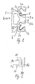
- An extruded profile, generally designated 1, points towards one another Mirror grooves 2, 3 and a central web 4 and a rear cable duct 5 on.
- the receiving grooves 2, 3 are essentially boot-shaped trained, and expand towards the profile foot 6 in such a way that they are separated from one another by webs 2c, 3c separate profile foot areas 2a and 2b and 3a and 3b run out.
- the one that ends in the profile foot region 2a, 3a outer wall 7 of the receiving grooves 2, 3 double curve, that formed from the wall 8 of the central web 4 inner boundary of the receiving grooves 2, 3 arcuate educated.
- the central web 4 has a partially elliptical shape Design on and also has undercuts on the bridge foot 9a, 9b.
- Fig. 2 shows a second, essentially ⁇ -shaped in cross section Fastening profile 10 with two profile legs 11 and 12.
- the first profile leg 12 is essentially quarter circle shaped and points to his free end of a substantially circular cross section Nose 13 on.
- the second profile leg 11 is in the essentially arch-shaped and resilient and has a smaller latch 14.
- the profile legs 11 and 12 are by the same dimension x with the largest external dimension of the partially elliptical Center web 4 spaced apart.
- the fastening device works as follows:
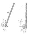
- a glass plate 15 for example Information sign with a grub screw 16 in the second profile 10 are fixed to a groove 17 first the one equipped with a circular nose 13 second fastening leg 12 in the receiving groove 3 of the first Extruded profile 1 introduced. Then the information sign 15 together with the second fastening profile 10 circular arc, as indicated by arrow 18, in the direction the first extruded profile is pivoted in the manner that the first profile leg 11 engages in the receiving groove 2.
- the first profile leg 11 springs with a latch 14 so far back that he has the outer contour of the central web 4 clasped at the - appropriately rounded - corner.
- the information plate 15 with the second profile 10 is completely pivoted, so that that shown in Fig.
- the information plate 15 In the opposite direction together with the second profile 10 pivoted out of the first extruded profile 1 and removed for example, to change the signage, or for cleaning purposes.
- extruded profile 1 itself is also useful through suitable connecting means to the stud frame Partition attached and is flush with surface-mounted versions can be integrated into the wall as a slot rail. As well can also be a wall-mounted version, just like one Ceiling or recessed versions can be realized. signs can be flat or at right angles to the wall (nose shields) be attached.
- an extruded profile 1 according to the invention also in a free-standing Information and / or technical stele can be integrated or even serve as a support profile for such stelae.
- Floor tanks can also be used with this, for example to connect IT and / or PBX and for the power supply of office equipment, be formed.
- multiple profiles can be used simultaneously, depending on the requirements covered with different materials on the outside can be.
Landscapes
- Engineering & Computer Science (AREA)
- General Engineering & Computer Science (AREA)
- Mechanical Engineering (AREA)
- Physics & Mathematics (AREA)
- General Physics & Mathematics (AREA)
- Theoretical Computer Science (AREA)
- Installation Of Indoor Wiring (AREA)
- Rear-View Mirror Devices That Are Mounted On The Exterior Of The Vehicle (AREA)
- Seal Device For Vehicle (AREA)
- Paper (AREA)
- Basic Packing Technique (AREA)
- Clamps And Clips (AREA)
Abstract
Description
- Fig. 1
- einen Querschnitt durch ein erfindungsgemäßes erstes Strangpressprofil,
- Fig. 2
- einen Querschnitt durch ein erfindungsgemäßes zweites, im wesentlichen π-förmiges Abdeck- oder Befestigungsprofil,
- Fig. 3
- ein Profil gemäß Fig. 2 im teilweisen Eingriff mit einem Profil gemäß Fig. 1,
- Fig. 4
- ein Profil gemäß Fig. 2 im vollständigen Eingriff mit einem Strangpressprofil gemäß Fig. 1.
Claims (11)
- Befestigungsvorrichtung zur Befestigung von Bauteilen, Installationsteilen, Informationselementen und dgl.,
gekennzeichnet durch ein erstes, insbesondere in eine Trennwand flächenbündig einsetzbares Strangpressprofil (1) mit zwei zu seiner Mittelachse spiegelbildlich ausgebildeten Aufnahmenuten (2, 3) zum Eingriff eines zweiten Profils (10). - Befestigungsvorrichtung nach Anspruch 1,
dadurch gekennzeichnet, dass die Aufnahmenuten (2, 3) stiefelförmig ausgebildet sind und sich einerseits doppelkurvenförmig (7), andererseits bogenförmig (8) zum Profilfuß (6) hin erweitern, und in zwei voneinander durch Stege (2c, 3c) getrennte Profilfußbereiche (2a, 2b, 3a, 3c) auslaufen. - Befestigungsvorrichtung nach Anspruch 1, 2,
dadurch gekennzeichnet, dass das Profil (1) einen teilellipsenförmigen Mittelsteg (4) mit bogenförmigen, zu den Aufnahmenuten (2, 3) hin gerichteten konvexen Wölbungen aufweist. - Befestigungsvorrichtung nach Anspruch 1 und/oder wenigstens einem der folgenden
dadurch gekennzeichnet, dass der teilellipsenförmige Mittelsteg (4) des ersten Profils (1) am Stegfuß beidseitig Hinterschneidungen (9a, 9b) aufweist. - Befestigungsvorrichtung nach Anspruch 1 und/oder wenigstens einem der folgenden,
dadurch gekennzeichnet, dass die Aufnahmenuten (2, 3) reibungserhöhende Mittel, insbesondere eine Gummierung, aufweisen. - Befestigungsvorrichtung nach Anspruch 1 und/oder wenigstens einem der folgenden,
gekennzeichnet durch ein zweites, querschnittlich im wesentlichen π-förmiges Abdeck- oder Befestigungsprofil (10) mit zwei Profilschenkeln (11, 12) zum Rasteingriff in das erste Strangpressprofil (1). - Befestigungsprofil nach Anspruch 5,
dadurch gekennzeichnet, dass ein in eine erste Aufnahmenut (3) des ersten Profils (1) eingreifender erster Profilschenkel (12) im wesentlichen viertelkreisförmig ausgebildet ist und an seinem freien Ende eine querschnittlich im wesentlichen kreisförmige Nase (13) aufweist. - Befestigungsprofil nach Anspruch 5, 6,
dadurch gekennzeichnet, dass ein in eine zweite Aufnahmenut (2) des ersten Profils (1) eingreifender zweiter Profilschenkel (11) im wesentlichen bogenförmig und federnd ausgebildet ist, eine Rastnase (14) aufweist und von dem ersten Profilschenkel (12) um das größte Außenmaß (X) des teilellipsenförmigen Mittelstegs (4) des ersten Profils (1) beabstandet angeordnet ist. - Befestigungsvorrichtung nach Anspruch 1 und/oder wenigstens einem der folgenden,
dadurch gekennzeichnet, dass das erste Strangpressprofil (1) rückseitig einen Kanal (5) zur Aufnahme von Elektrokabeln und dgl. aufweist. - Befestigungsvorrichtung nach Anspruch 1 und/oder wenigstens einem der folgenden,
dadurch gekennzeichnet, dass der Mittelsteg (4) des ersten Strangpressprofils (1) wenigstens bereichsweise Durchbrechungen und/oder Schlitze aufweist. - Befestigungsvorrichtung nach Anspruch 1 und/oder wenigstens einem der folgenden,
gekennzeichnet durch ein einstückig mit dem zweiten Befestigungsprofil (10) ausgebildetes Aufnahmeprofil für zusätzliche Bauteile.
Applications Claiming Priority (2)
| Application Number | Priority Date | Filing Date | Title |
|---|---|---|---|
| DE20308129U | 2003-05-24 | ||
| DE20308129U DE20308129U1 (de) | 2003-05-24 | 2003-05-24 | Befestigungsvorrichtung |
Publications (2)
| Publication Number | Publication Date |
|---|---|
| EP1482185A1 true EP1482185A1 (de) | 2004-12-01 |
| EP1482185B1 EP1482185B1 (de) | 2010-07-28 |
Family
ID=27763204
Family Applications (1)
| Application Number | Title | Priority Date | Filing Date |
|---|---|---|---|
| EP04009646A Expired - Lifetime EP1482185B1 (de) | 2003-05-24 | 2004-04-23 | Befestigungsvorrichtung |
Country Status (3)
| Country | Link |
|---|---|
| EP (1) | EP1482185B1 (de) |
| AT (1) | ATE475808T1 (de) |
| DE (2) | DE20308129U1 (de) |
Cited By (1)
| Publication number | Priority date | Publication date | Assignee | Title |
|---|---|---|---|---|
| FR3010427A1 (fr) * | 2013-09-09 | 2015-03-13 | Espaciel | Structure porteuse permettant la fixation d'un panneau par une unique barrette de clipsage |
Families Citing this family (1)
| Publication number | Priority date | Publication date | Assignee | Title |
|---|---|---|---|---|
| DE102009030799A1 (de) * | 2009-06-27 | 2011-07-28 | Contecta GmbH, 55481 | Befestigungselement |
Citations (6)
| Publication number | Priority date | Publication date | Assignee | Title |
|---|---|---|---|---|
| DE29607236U1 (de) * | 1996-04-22 | 1996-06-27 | Dreer, Franz, 86825 Bad Wörishofen | Schnellverbindung für plattenförmige Bauelemente |
| EP0882616A1 (de) * | 1997-06-02 | 1998-12-09 | Renault VI | Vorrichtung zur Befestigung einer Fensterscheibe |
| FR2774437A1 (fr) * | 1998-02-02 | 1999-08-06 | Palkit | Ensemble d'elements pour l'assemblage d'un panneau a un objet, notamment a un autre panneau |
| EP1068820A1 (de) * | 1999-07-15 | 2001-01-17 | Premark RWP Holdings, Inc. | Integration/Bausatz einer Arbeitsplatte und Wandanschlussleiste |
| DE10002075A1 (de) * | 1999-09-20 | 2001-03-29 | Solarlux Aluminium Sys Gmbh | Profilrahmen |
| DE20102332U1 (de) | 2001-02-08 | 2001-04-26 | F.EE GmbH Automation, 92431 Neunburg | Profilstab |
-
2003
- 2003-05-24 DE DE20308129U patent/DE20308129U1/de not_active Expired - Lifetime
-
2004
- 2004-04-23 DE DE502004011435T patent/DE502004011435D1/de not_active Expired - Lifetime
- 2004-04-23 EP EP04009646A patent/EP1482185B1/de not_active Expired - Lifetime
- 2004-04-23 AT AT04009646T patent/ATE475808T1/de active
Patent Citations (6)
| Publication number | Priority date | Publication date | Assignee | Title |
|---|---|---|---|---|
| DE29607236U1 (de) * | 1996-04-22 | 1996-06-27 | Dreer, Franz, 86825 Bad Wörishofen | Schnellverbindung für plattenförmige Bauelemente |
| EP0882616A1 (de) * | 1997-06-02 | 1998-12-09 | Renault VI | Vorrichtung zur Befestigung einer Fensterscheibe |
| FR2774437A1 (fr) * | 1998-02-02 | 1999-08-06 | Palkit | Ensemble d'elements pour l'assemblage d'un panneau a un objet, notamment a un autre panneau |
| EP1068820A1 (de) * | 1999-07-15 | 2001-01-17 | Premark RWP Holdings, Inc. | Integration/Bausatz einer Arbeitsplatte und Wandanschlussleiste |
| DE10002075A1 (de) * | 1999-09-20 | 2001-03-29 | Solarlux Aluminium Sys Gmbh | Profilrahmen |
| DE20102332U1 (de) | 2001-02-08 | 2001-04-26 | F.EE GmbH Automation, 92431 Neunburg | Profilstab |
Cited By (1)
| Publication number | Priority date | Publication date | Assignee | Title |
|---|---|---|---|---|
| FR3010427A1 (fr) * | 2013-09-09 | 2015-03-13 | Espaciel | Structure porteuse permettant la fixation d'un panneau par une unique barrette de clipsage |
Also Published As
| Publication number | Publication date |
|---|---|
| DE20308129U1 (de) | 2003-08-14 |
| EP1482185B1 (de) | 2010-07-28 |
| DE502004011435D1 (de) | 2010-09-09 |
| ATE475808T1 (de) | 2010-08-15 |
Similar Documents
| Publication | Publication Date | Title |
|---|---|---|
| DE102012202148A1 (de) | Lichtbandsystem | |
| DE2556813A1 (de) | Bausatz zum herstellen von raumfachwerken fuer ausstellungs- und ladenbau | |
| DE202009017793U1 (de) | Leuchtenprofil | |
| EP2243998A1 (de) | Wand- und Deckensystem | |
| EP2247892A1 (de) | Leuchte | |
| EP0305892B1 (de) | Multifunktionales Rahmenelement | |
| WO2016146113A2 (de) | Langfeldleuchte bestehend aus einem; zwei oder mehreren metallprofilkörpermodulen, dazu angepassten led-modulen und verbindungselementen | |
| AT17668U1 (de) | Beleuchtungssystem mit lichtdurchlässigem Abdeckelement | |
| AT509686A1 (de) | Halterungsprofil mit zumindest einer beleuchtungseinheit | |
| DE102022126249A1 (de) | Befestigungssystem für eine Leuchte, Befestigungselement sowie eine Leuchte | |
| DE60216877T2 (de) | Tragevorrichtung für Lamellen | |
| EP1482185B1 (de) | Befestigungsvorrichtung | |
| DE102007059171A1 (de) | Glaskantenbeleuchtung | |
| EP2002177B1 (de) | Leuchtenanordnung | |
| AT514331B1 (de) | Trennwandsystem aus Fixglaselementen und zumindest einem Glastürelement | |
| DE19848511C2 (de) | Bausatz für Kabelkanäle eines Arbeitsplatz-Möbels | |
| DE69610711T2 (de) | Stift- und gleitverfahren zur montage und befestigung einer verkleidung | |
| AT527815B1 (de) | Zum heizen oder kühlen einer räumlichkeit betreibbares deckenelement, sowie funktionsdecke mit derartigen deckenelementen | |
| DE202011003620U1 (de) | Befestigungsmittel zum Befestigen eines Rahmenelementes an einer Montageplatte, Rahmenelement sowie Installationseinrichtung | |
| DE9306728U1 (de) | Gehäuse für Kühlaggregate, Klimageräte o.dgl. | |
| DE102018106230A1 (de) | Modulare Deckenleuchte | |
| DE9101721U1 (de) | Leuchte mit einer langgestreckten Tragschiene für mehrere in deren Längsrichtung hintereinanderliegend angeordnete Lampen | |
| DE9303155U1 (de) | Duschkabine | |
| AT528462A1 (de) | Funktionsdecke mit zum Heizen oder Kühlen einer Räumlichkeit betreibbaren Deckenelementen | |
| DE10160740A1 (de) | Bausatz zur Errichtung eines Präsentationsstands für eine Messe oder dgl. |
Legal Events
| Date | Code | Title | Description |
|---|---|---|---|
| PUAI | Public reference made under article 153(3) epc to a published international application that has entered the european phase |
Free format text: ORIGINAL CODE: 0009012 |
|
| AK | Designated contracting states |
Kind code of ref document: A1 Designated state(s): AT BE BG CH CY CZ DE DK EE ES FI FR GB GR HU IE IT LI LU MC NL PL PT RO SE SI SK TR |
|
| AX | Request for extension of the european patent |
Extension state: AL HR LT LV MK |
|
| 17P | Request for examination filed |
Effective date: 20050521 |
|
| AKX | Designation fees paid |
Designated state(s): AT BE BG CH CY CZ DE DK EE ES FI FR GB GR HU IE IT LI LU MC NL PL PT RO SE SI SK TR |
|
| 17Q | First examination report despatched |
Effective date: 20080108 |
|
| RAP1 | Party data changed (applicant data changed or rights of an application transferred) |
Owner name: MABEG LEITSYSTEME GMBH |
|
| GRAP | Despatch of communication of intention to grant a patent |
Free format text: ORIGINAL CODE: EPIDOSNIGR1 |
|
| GRAS | Grant fee paid |
Free format text: ORIGINAL CODE: EPIDOSNIGR3 |
|
| GRAA | (expected) grant |
Free format text: ORIGINAL CODE: 0009210 |
|
| AK | Designated contracting states |
Kind code of ref document: B1 Designated state(s): AT BE BG CH CY CZ DE DK EE ES FI FR GB GR HU IE IT LI LU MC NL PL PT RO SE SI SK TR |
|
| REG | Reference to a national code |
Ref country code: GB Ref legal event code: FG4D Free format text: NOT ENGLISH |
|
| REG | Reference to a national code |
Ref country code: CH Ref legal event code: EP |
|
| REG | Reference to a national code |
Ref country code: IE Ref legal event code: FG4D Free format text: LANGUAGE OF EP DOCUMENT: GERMAN |
|
| REF | Corresponds to: |
Ref document number: 502004011435 Country of ref document: DE Date of ref document: 20100909 Kind code of ref document: P |
|
| REG | Reference to a national code |
Ref country code: CH Ref legal event code: NV Representative=s name: BOVARD AG PATENTANWAELTE Ref country code: CH Ref legal event code: PCOW Free format text: MABEG LEITSYSTEME GMBH;FERDINAND-GABRIEL-WEG 7;59494 SOEST (DE) |
|
| REG | Reference to a national code |
Ref country code: NL Ref legal event code: T3 |
|
| PG25 | Lapsed in a contracting state [announced via postgrant information from national office to epo] |
Ref country code: FI Free format text: LAPSE BECAUSE OF FAILURE TO SUBMIT A TRANSLATION OF THE DESCRIPTION OR TO PAY THE FEE WITHIN THE PRESCRIBED TIME-LIMIT Effective date: 20100728 |
|
| PG25 | Lapsed in a contracting state [announced via postgrant information from national office to epo] |
Ref country code: PT Free format text: LAPSE BECAUSE OF FAILURE TO SUBMIT A TRANSLATION OF THE DESCRIPTION OR TO PAY THE FEE WITHIN THE PRESCRIBED TIME-LIMIT Effective date: 20101129 Ref country code: PL Free format text: LAPSE BECAUSE OF FAILURE TO SUBMIT A TRANSLATION OF THE DESCRIPTION OR TO PAY THE FEE WITHIN THE PRESCRIBED TIME-LIMIT Effective date: 20100728 Ref country code: SI Free format text: LAPSE BECAUSE OF FAILURE TO SUBMIT A TRANSLATION OF THE DESCRIPTION OR TO PAY THE FEE WITHIN THE PRESCRIBED TIME-LIMIT Effective date: 20100728 Ref country code: BG Free format text: LAPSE BECAUSE OF FAILURE TO SUBMIT A TRANSLATION OF THE DESCRIPTION OR TO PAY THE FEE WITHIN THE PRESCRIBED TIME-LIMIT Effective date: 20101028 Ref country code: CY Free format text: LAPSE BECAUSE OF FAILURE TO SUBMIT A TRANSLATION OF THE DESCRIPTION OR TO PAY THE FEE WITHIN THE PRESCRIBED TIME-LIMIT Effective date: 20100728 |
|
| REG | Reference to a national code |
Ref country code: IE Ref legal event code: FD4D |
|
| PG25 | Lapsed in a contracting state [announced via postgrant information from national office to epo] |
Ref country code: SE Free format text: LAPSE BECAUSE OF FAILURE TO SUBMIT A TRANSLATION OF THE DESCRIPTION OR TO PAY THE FEE WITHIN THE PRESCRIBED TIME-LIMIT Effective date: 20100728 Ref country code: GR Free format text: LAPSE BECAUSE OF FAILURE TO SUBMIT A TRANSLATION OF THE DESCRIPTION OR TO PAY THE FEE WITHIN THE PRESCRIBED TIME-LIMIT Effective date: 20101029 |
|
| REG | Reference to a national code |
Ref country code: CH Ref legal event code: PFA Owner name: MABEG LEITSYSTEME GMBH Free format text: MABEG LEITSYSTEME GMBH#FERDINAND-GABRIEL-WEG 7#59494 SOEST (DE) -TRANSFER TO- MABEG LEITSYSTEME GMBH#FERDINAND-GABRIEL-WEG 7#59494 SOEST (DE) |
|
| PG25 | Lapsed in a contracting state [announced via postgrant information from national office to epo] |
Ref country code: DK Free format text: LAPSE BECAUSE OF FAILURE TO SUBMIT A TRANSLATION OF THE DESCRIPTION OR TO PAY THE FEE WITHIN THE PRESCRIBED TIME-LIMIT Effective date: 20100728 Ref country code: IE Free format text: LAPSE BECAUSE OF FAILURE TO SUBMIT A TRANSLATION OF THE DESCRIPTION OR TO PAY THE FEE WITHIN THE PRESCRIBED TIME-LIMIT Effective date: 20100728 |
|
| PG25 | Lapsed in a contracting state [announced via postgrant information from national office to epo] |
Ref country code: EE Free format text: LAPSE BECAUSE OF FAILURE TO SUBMIT A TRANSLATION OF THE DESCRIPTION OR TO PAY THE FEE WITHIN THE PRESCRIBED TIME-LIMIT Effective date: 20100728 Ref country code: SK Free format text: LAPSE BECAUSE OF FAILURE TO SUBMIT A TRANSLATION OF THE DESCRIPTION OR TO PAY THE FEE WITHIN THE PRESCRIBED TIME-LIMIT Effective date: 20100728 Ref country code: RO Free format text: LAPSE BECAUSE OF FAILURE TO SUBMIT A TRANSLATION OF THE DESCRIPTION OR TO PAY THE FEE WITHIN THE PRESCRIBED TIME-LIMIT Effective date: 20100728 Ref country code: CZ Free format text: LAPSE BECAUSE OF FAILURE TO SUBMIT A TRANSLATION OF THE DESCRIPTION OR TO PAY THE FEE WITHIN THE PRESCRIBED TIME-LIMIT Effective date: 20100728 Ref country code: IT Free format text: LAPSE BECAUSE OF FAILURE TO SUBMIT A TRANSLATION OF THE DESCRIPTION OR TO PAY THE FEE WITHIN THE PRESCRIBED TIME-LIMIT Effective date: 20100728 |
|
| PLBE | No opposition filed within time limit |
Free format text: ORIGINAL CODE: 0009261 |
|
| STAA | Information on the status of an ep patent application or granted ep patent |
Free format text: STATUS: NO OPPOSITION FILED WITHIN TIME LIMIT |
|
| PG25 | Lapsed in a contracting state [announced via postgrant information from national office to epo] |
Ref country code: ES Free format text: LAPSE BECAUSE OF FAILURE TO SUBMIT A TRANSLATION OF THE DESCRIPTION OR TO PAY THE FEE WITHIN THE PRESCRIBED TIME-LIMIT Effective date: 20101108 |
|
| 26N | No opposition filed |
Effective date: 20110429 |
|
| PGFP | Annual fee paid to national office [announced via postgrant information from national office to epo] |
Ref country code: CH Payment date: 20110428 Year of fee payment: 8 |
|
| REG | Reference to a national code |
Ref country code: DE Ref legal event code: R097 Ref document number: 502004011435 Country of ref document: DE Effective date: 20110429 |
|
| PGFP | Annual fee paid to national office [announced via postgrant information from national office to epo] |
Ref country code: NL Payment date: 20110429 Year of fee payment: 8 Ref country code: GB Payment date: 20110428 Year of fee payment: 8 Ref country code: AT Payment date: 20110428 Year of fee payment: 8 |
|
| BERE | Be: lapsed |
Owner name: MABEG LEITSYSTEME G.M.B.H. Effective date: 20110430 |
|
| PG25 | Lapsed in a contracting state [announced via postgrant information from national office to epo] |
Ref country code: MC Free format text: LAPSE BECAUSE OF NON-PAYMENT OF DUE FEES Effective date: 20110430 |
|
| REG | Reference to a national code |
Ref country code: FR Ref legal event code: ST Effective date: 20111230 |
|
| PG25 | Lapsed in a contracting state [announced via postgrant information from national office to epo] |
Ref country code: BE Free format text: LAPSE BECAUSE OF NON-PAYMENT OF DUE FEES Effective date: 20110430 Ref country code: FR Free format text: LAPSE BECAUSE OF NON-PAYMENT OF DUE FEES Effective date: 20110502 |
|
| REG | Reference to a national code |
Ref country code: NL Ref legal event code: V1 Effective date: 20121101 |
|
| REG | Reference to a national code |
Ref country code: CH Ref legal event code: PL |
|
| REG | Reference to a national code |
Ref country code: AT Ref legal event code: MM01 Ref document number: 475808 Country of ref document: AT Kind code of ref document: T Effective date: 20120423 |
|
| GBPC | Gb: european patent ceased through non-payment of renewal fee |
Effective date: 20120423 |
|
| PG25 | Lapsed in a contracting state [announced via postgrant information from national office to epo] |
Ref country code: GB Free format text: LAPSE BECAUSE OF NON-PAYMENT OF DUE FEES Effective date: 20120423 Ref country code: LI Free format text: LAPSE BECAUSE OF NON-PAYMENT OF DUE FEES Effective date: 20120430 Ref country code: AT Free format text: LAPSE BECAUSE OF NON-PAYMENT OF DUE FEES Effective date: 20120423 Ref country code: CH Free format text: LAPSE BECAUSE OF NON-PAYMENT OF DUE FEES Effective date: 20120430 |
|
| PG25 | Lapsed in a contracting state [announced via postgrant information from national office to epo] |
Ref country code: NL Free format text: LAPSE BECAUSE OF NON-PAYMENT OF DUE FEES Effective date: 20121101 |
|
| PG25 | Lapsed in a contracting state [announced via postgrant information from national office to epo] |
Ref country code: TR Free format text: LAPSE BECAUSE OF FAILURE TO SUBMIT A TRANSLATION OF THE DESCRIPTION OR TO PAY THE FEE WITHIN THE PRESCRIBED TIME-LIMIT Effective date: 20100728 |
|
| PG25 | Lapsed in a contracting state [announced via postgrant information from national office to epo] |
Ref country code: HU Free format text: LAPSE BECAUSE OF FAILURE TO SUBMIT A TRANSLATION OF THE DESCRIPTION OR TO PAY THE FEE WITHIN THE PRESCRIBED TIME-LIMIT Effective date: 20100728 |
|
| PGFP | Annual fee paid to national office [announced via postgrant information from national office to epo] |
Ref country code: LU Payment date: 20150423 Year of fee payment: 12 |
|
| PG25 | Lapsed in a contracting state [announced via postgrant information from national office to epo] |
Ref country code: LU Free format text: LAPSE BECAUSE OF NON-PAYMENT OF DUE FEES Effective date: 20160423 |
|
| PGFP | Annual fee paid to national office [announced via postgrant information from national office to epo] |
Ref country code: DE Payment date: 20230505 Year of fee payment: 20 |
|
| REG | Reference to a national code |
Ref country code: DE Ref legal event code: R071 Ref document number: 502004011435 Country of ref document: DE |