EP1481882A2 - Steering damper - Google Patents
Steering damper Download PDFInfo
- Publication number
- EP1481882A2 EP1481882A2 EP20040012506 EP04012506A EP1481882A2 EP 1481882 A2 EP1481882 A2 EP 1481882A2 EP 20040012506 EP20040012506 EP 20040012506 EP 04012506 A EP04012506 A EP 04012506A EP 1481882 A2 EP1481882 A2 EP 1481882A2
- Authority
- EP
- European Patent Office
- Prior art keywords
- steering
- damping force
- fluid path
- angular velocity
- fluid
- Prior art date
- Legal status (The legal status is an assumption and is not a legal conclusion. Google has not performed a legal analysis and makes no representation as to the accuracy of the status listed.)
- Granted
Links
Images



Classifications
-
- F—MECHANICAL ENGINEERING; LIGHTING; HEATING; WEAPONS; BLASTING
- F16—ENGINEERING ELEMENTS AND UNITS; GENERAL MEASURES FOR PRODUCING AND MAINTAINING EFFECTIVE FUNCTIONING OF MACHINES OR INSTALLATIONS; THERMAL INSULATION IN GENERAL
- F16F—SPRINGS; SHOCK-ABSORBERS; MEANS FOR DAMPING VIBRATION
- F16F9/00—Springs, vibration-dampers, shock-absorbers, or similarly-constructed movement-dampers using a fluid or the equivalent as damping medium
- F16F9/10—Springs, vibration-dampers, shock-absorbers, or similarly-constructed movement-dampers using a fluid or the equivalent as damping medium using liquid only; using a fluid of which the nature is immaterial
- F16F9/14—Devices with one or more members, e.g. pistons, vanes, moving to and fro in chambers and using throttling effect
- F16F9/145—Devices with one or more members, e.g. pistons, vanes, moving to and fro in chambers and using throttling effect involving only rotary movement of the effective parts
-
- B—PERFORMING OPERATIONS; TRANSPORTING
- B62—LAND VEHICLES FOR TRAVELLING OTHERWISE THAN ON RAILS
- B62K—CYCLES; CYCLE FRAMES; CYCLE STEERING DEVICES; RIDER-OPERATED TERMINAL CONTROLS SPECIALLY ADAPTED FOR CYCLES; CYCLE AXLE SUSPENSIONS; CYCLE SIDECARS, FORECARS, OR THE LIKE
- B62K21/00—Steering devices
- B62K21/08—Steering dampers
Definitions
- the present invention relates to a steering damper.
- a type of steering damper which controls damping force generated in the steering system by controlling a pressure control valve provided in a fluid path of a steering damper body so as to change damping force generated by the pressure control valve (for example, refer to Japanese Examined Patent Application, Second Publication No. H7-74023).
- a load applied to a front wheel of a vehicle is measured, and electrical current supplied to a solenoid that is installed in a pressure control valve is controlled so as to increase a damping force when the load is decreased.
- the relationship between a steering angular velocity and the damping force of the steering system is set to be basically linear, when the steering damper is configured so that an operation force at the steering handle at the beginning of a steering operation is set to be low, the vibrations due to road surface disturbances in a low steering angular velocity region during high speed driving cannot be absorbed.
- the steering damper is configured so as to absorb the vibrations due to road surface disturbances in a low steering angular velocity region during high speed driving, the operation force at the steering handle at the beginning of a steering operation becomes high.
- the present invention was made in view of the above circumferences, and an object thereof is to provide a steering damper which simultaneously achieves two objects of setting the operation force at the steering handle at the beginning of a steering operation to be low, and of absorbing the vibrations due to road surface disturbances in a low steering angular velocity region during high speed driving.
- the present invention provides a steering damper including: a steering damper body installed in a steering system of a vehicle, and having a fluid path therein; and a pressure control valve for controlling a damping force in the steering system, and provided in the fluid path, wherein the pressure control valve controls the damping force so that an increasing rate of the damping force with respect to a steering angular velocity when the steering angular velocity is large is lower than that when the steering angular velocity is small.
- the pressure control valve may control the damping force so that the increasing rate of the damping force with respect to the steering angular velocity when the steering angular velocity is larger than a predetermined value is lower than that when the steering angular velocity is smaller than or equal to the predetermined value.
- the steering damper body may include a fluid chamber having an entrance and an exit, a first fluid path connected to the entrance of the fluid chamber, a second fluid path connected to the exit of the fluid chamber, and a connection fluid path connecting the first fluid path to the second fluid path.
- the pressure control valve may be a relief valve provided in the connection fluid path.
- the present invention further provides a steering damper including: a steering damper body installed in a steering system of a vehicle, and having a fluid path therein; and a pressure control valve for controlling a damping force in the steering system, and provided in the fluid path, wherein the pressure control valve controls the damping force so that an increasing rate of the damping force with respect to a steering angular velocity when the damping force is large is lower than that when the damping force is small.
- the pressure control valve may control the damping force so that the increasing rate of the damping force with respect to the steering angular velocity when the damping force is larger than a predetermined value is lower than that when the damping force is smaller than or equal to the predetermined value.
- the relationship between the steering angular velocity and the damping force of the steering system is not linear over the entire steering angular velocity region, and the steering damper is configured so that the increasing rate of the damping force with respect to the steering angular velocity of the steering system when the steering angular velocity is large is lower than that when the steering angular velocity is small, or the increasing rate of the damping force when the damping force is large is lower than that when the damping force is small; therefore, the damping force can be quickly increased as the steering angular velocity is increased from a state in which the steering angular velocity is small and the damping force is low.
- the two objects of setting the operation force at the steering handle at the beginning of a steering operation to be low, and of absorbing the vibrations due to road surface disturbances in a low steering angular velocity region during high speed driving can be simultaneously achieved.
- the damping force will not exceed a predetermined value.
- a motorcycle 1 is provided with a motorcycle body frame 2 in the approximate center, and a front fork 5 which supports a front wheel 4 is steerably supported through a steering stem 6 by a head pipe 3 which is provided in the front end of a motorcycle body frame 2.
- a main frame 7 is provided from the head pipe 3 of the motorcycle body frame 2 so as to extend obliquely behind and downward after being separated to the right and left, and to extend downwardly through bends.
- Pivot sections 8 are provided in the approximately central front end sections of the parts of the main frame 7 extending downward, and rear forks 10 supporting a rear wheel 9 are supported rockably by the pivot sections 8.
- slightly rear sections of the parts supported by the pivot sections 8 of the rear forks 10 are joined to the main frame 7 through rear cushions 11 and link sections 12.
- a seat frame 13 is joined to rear sections of the main frame 7.
- a fuel tank 14 is arranged above the main frame 7, and an engine body 15 of a water-cooled parallel four-cylinder engine is arranged below the main frame 7. From the front part of the main frame 7, engine hangers 16 are extended downwardly, and the engine hangers 16 support the engine body 15 with other junctions for basic engine support which are provided in the main frame 7.
- a rider's seat 17 and a pillion seat 18 are respectively supported by a seat frame 13.
- rider's steps 19 are attached in the rear sections of the pivot sections 8 of the motorcycle body frame 2
- co-rider's steps 20 are attached in the lower portion of the seat frame 13.
- a pair of right and left handles 21 and 21 is attached to the top end of the front fork 5 through a top bridge 49.
- a front nose section of the motorcycle 1 is covered with a front cowl 25, and the vicinity of the seat frame 13 is covered by a rear cowl 26.
- a retractable prop stand 27 is arranged in a lower left side of the motorcycle body frame 2, the prop stand 27 which supports the motorcycle body of the motorcycle 1 in a rising state oblique to a left side.
- a front brake device 30 is constituted by a brake caliper 28 being attached to a bottom end section of the front fork 5 and a brake rotor 29, corresponding to the brake caliper 28, being attached to a front wheel 4.
- a front fender 31 covering over the front wheel 4 is attached to a bottom end section of the front fork 5.
- a rear sprocket 32 is attached to a left side of a rear wheel 9 so as to rotate with the rear wheel 9 integrally.
- a drive chain 34 is looped over the rear sprocket 32 and a drive sprocket 33 arranged in a lower left side of the engine body 15. Then, a driving force of the engine body 15 is transmitted to the rear wheel 9.
- a front rear fender 35 covering over an upper front side of the rear fork 10 is attached to an upper portion of the rear wheel 9, and a rear fender 36 covering over an upper rear side of the rear wheel 9 is attached to a lower portion of the rear cowl 26.
- a rear brake device which has the same structure as the front brake device 30 of the front wheel 4 is provided in the rear frame 10.
- a cylinder body 40 of the engine body 15 is arranged so as to slightly incline forward over a crankcase 41.
- Throttle bodies 42 corresponding to respective cylinders are joined to rear sections of the cylinder body 40, and respective throttle bodies 42 are joined to an air cleaner case 43 located between the main frame 7 and fuel tank 14.
- exhaust pipes 44 corresponding to respective cylinders are joined to front parts of the cylinder body 40.
- the exhaust pipes 44 extend forward from a front wall 45 of the cylinder body 40, are curved and extend downwardly, extend in front of and under the crankcase 41, and extend to a location behind the engine body 15.
- the above-mentioned steering stem 6, a top bridge 49 located above a bottom bridge of the steering stem 6 in parallel to the bottom bridge, the steering handle 21, and the like constitute the steering system 50 which steers the front wheel 4.
- the steering system 50 is provided with the steering damper 51 (refer to FIGS. 2 and 3).
- the steering damper 51 is for decreasing the vibration of the steering handle 21 which is caused by a kickback, etc., or absorbing vibration in a low steering angular velocity region which is caused by road surface disturbances during high speed driving.
- two types of steering dampers are known, one is a rod type and the other is a rotary type, and a rotary type steering damper 51, which is suitable for reducing the size thereof, is used in this embodiment.
- the steering damper 51 includes a steering damper main body 51 A being constituted by a housing 52 and a shaft 53 which penetrates a bottom face section of the housing 52 and protruding outside, and a pressure control valve 68 intermediately installed in the fluid path of the steering damper main body 51A.
- the housing 52 is attached to a junction 3a provided with extending behind with the head pipe 3 through first and second brackets 54 and 55.
- the shaft 53 is attached to the top bridge 49 through a link mechanism 56.
- the first bracket 54 has an approximately enclosed type shape whose inside is scooped out, and has right and left side wall sections 54a and 54a, a bottom plate section 54b, and a leg section 54c which has an approximately Y shape and is connected to rear edge sections of the side plate section 54a, and bottom plate section 54b. Then, respective mounting holes 54d, 54d, and 54d are formed in top face sections of the side wall sections 54a and 54a, and a top face section of the leg section 54c, and the above-mentioned steering damper 51 is bolted through the mounting holes 54d.
- mounting holes 54e and 54e are formed in the bottom plate section 54b, and mounting holes 54f and 54f are formed in the leg section 54c respectively, and the first bracket 54 is bolted to the junction 3a of the head pipe 3 through the mounting holes 54e.
- the second bracket 55 has a base 55a formed in an approximately rectangular parallelepiped shape, and right and left overhang sections 55b and 55b protruding from both sides of the base upward.
- Mounting holes 55c and 55c are formed in the base 55a so as to be coaxial with the mounting holes 54f and 54f of the first bracket 54. Then, one bolt is inserted into the mounting holes 54f and 55c, both of which are coaxial, in the state that both the first bracket 54 and second bracket 55 are stacked. With the bolt, the second bracket 55 is attached to the junction 3a of the above-mentioned head pipe 3 with the first bracket 54.
- an end section 60a of an arm 60 is attached to a shaft 53 which protrudes under the steering damper main body 51 A.
- An end section of an elongated figure-8-shape linkage 63 is spherically supported by another end section 60b of the arm 60, which is branched into two, through a bolt 61, a ball member 62 fitted on the outer periphery of the bolt 61, and the like.
- another end section of the linkage 63 is spherically supported by a junction 49a, formed in the top bridge 49, through a bolt 64 and a ball member 65 fitted on the outer periphery of the bolt 64. That is, the link mechanism 56 which transmits a motion of the top bridge to the shaft 53 is constituted by the arm 60, bolts 61 and 64, ball members 62 and 65, and linkage 63.
- the housing 52 of the steering damper main body 51 A is attached in the top bridge 49 so as to extend backward.
- a linear solenoid 69 which drives and controls a pressure control valve 68 is located below an extruding section 52a extending from the top bridge 49 of the housing 52 backward.
- a concavity 14a is formed in the front part of the fuel tank 14.
- reference numeral 70 denotes an ignition switch located ahead of the head pipe 3.
- the housing 52 of the steering damper main body 51 A is constituted by a body 71 and a cap 72.
- a fan-like concavity 73 is formed in a top face section of the body 71, and a fluid chamber 74 is formed by the concavity 73 being covered by the cap 72.
- the fluid chamber 74 is partitioned by a vane 75 into two, right and left, fluid chambers 74a and 74b.
- a base 75a of the vane 75 is formed in a cylindrical shape, and the shaft 53 is joined with the cylindrical section in a fixed state so as to rotate integrally with the vane 75 through fixing means such as a spline.
- the vane 75 is supported by the shaft 53 in a rockable manner with respect to the housing 52.
- a groove 75b is continuously formed on a top end, on a bottom end, and on a rear end of the vane 75, each of which faces the inner circumferential surface of the fluid chamber 74.
- a sealing member 76 which is formed in a U-shape so as to match the shape of the groove 75b, is fitted in the groove 75b.
- the groove 75b and sealing member 76 do not reach the shaft 53, but the groove 75b is formed, and the sealing member 76 is fitted in the groove 75b, up to points separated from the shaft 53.
- washers 77a and 77b for sealing are fitted so as to abut against upper and lower face sections of the base 75a of the vane 75. Furthermore, portions of the outer peripheries of washers 77a and 77b for the sealing of upper and lower sides thereof abut against the sealing member 76.
- two fluid chambers 74a and 74b partitioned inside the housing 52 are maintained to be sealed from each other in a fluid-tight manner, and are also maintained to be sealed from the shaft 53 in a fluid-tight manner, by the sealing member 76 and washers 77a and 77b for sealing.
- a bushing 78 is fitted on an upper part of an area where the washer 77a for the sealing of the shaft 53 is fitted, and a circlip 79 is fitted on a lower part of an area where the washer 77a for sealing is fitted, respectively.
- a bushing 80 and an oil seal 81 are fitted on a lower part of an area where the washer 77b for the sealing of the lower side of the shaft 53 is fitted, respectively.
- the fluid paths 83 and 84 in a discharge side where hydraulic fluid is exhausted from the right and left fluid chambers 74a and 74b are formed in the body 71 of the above-mentioned housing 52 so that they extend back further from rear edges of inner circumferential surfaces of the fluid chambers 74a and 74b, and so that they are arranged substantially parallel to each other.
- Check valves 85 and 85 are intermediately installed in the fluid paths 83 and 84, respectively.
- the rear edge sections of the fluid paths 83 and 84 are formed so that a fluid path 86 which makes the fluid paths 83 and 84 communicate mutually may be approximately orthogonal to the fluid paths 83 and 84.
- the fluid path 86 is joined to a fluid path 87 in a lower side, extending so as to be substantially orthogonal to the fluid path 86, through the pressure control valve 68 located in the vertical direction (refer to FIG. 12).
- the fluid path 87 extends forward from an area in which the pressure control valve 68 is provided so as to reach under the fluid chamber 74, and communicates with the fluid path 88 whose front end is approximately orthogonal to the fluid path 87.
- check valves 89 and 89 are intermediately installed, respectively.
- both right and left ends of the fluid path 87 rise upward and communicate with the above-mentioned right and left fluid chambers 74a and 74b respectively.
- the fluid path 88 acts as a fluid path in an entrance side to which the once exhausted hydraulic fluid is returned again to the fluid chambers 74a and 74b.
- the fluid path 87 where the above-mentioned electric pressure control valve 68 is intermediately installed becomes a connecting fluid path which makes the fluid paths in the entrance side and discharge side in view of the fluid chamber communicate.
- the fluid paths 83, 84, 86, 87, and 88 are formed in an upper portion and in a lower portion, i.e., two steps, of the body 7 of the housing 52.
- Both the check valves 85 and 89 have the same structure.
- a valve body 85a not only a valve seat 85b is provided, but also a ball 85c is contained.
- the ball 85c is suitably urged by a spring 85d so as to abut against the valve seat 85b.
- the check valve 85 prevents the flow of the fluid in the reverse direction.
- the check valve 85 prevents the flow of the hydraulic fluid in the reverse direction.
- the check valve 89 prevents the flow of the hydraulic fluid in the reverse direction.
- the pressure control valve 68 varies a damping force of the steering damper 51.
- the pressure control valve 68 not only is a valve seat 68b provided in a valve body 68a, but also a poppet 68c is contained so as to face the valve seat 68b.
- the poppet 68c is suitably urged by a spring 68d intermediately installed between a base spring seat of the poppet 68c, and the valve seat 68b so as to depart from the valve seat 68b.
- An upper end of a push rod 68e is inserted into a lower edge of the poppet 68c, and a lower edge of the push rod 68e is joined to the linear solenoid 69. Then, pressure adjustment is performed by the energizing operation of the linear solenoid 69 so that the poppet 68c may resist the urging force of the spring 68d for its head to abut against the valve seat 68c.
- a location of the poppet 68c is settled by the differential pressure between the right and left fluid chambers 74a and 74b inside the housing 52 which communicate with spaces of its head and base, the urging force of the spring 68d, and an exciting force of the linear solenoid 69 through the push rod 68e.
- the poppet 68c abuts on the valve seat 68b for the pressure control valve 68 concerned to be in a closed state.
- linear solenoid 69 is controlled by a controller, which is not illustrated, according to vehicle speed or vehicle body acceleration.
- a bypass fluid path 91 is formed between the fluid path 86 and fluid path 87, and a relief valve 92 is intermediately installed in the bypass fluid path 91.
- the relief valve 92 has the structure that not only a valve seat 92b is provided in a valve body 92a, but also a ball 92c is contained, the ball 92c which is energized toward the valve seat 92b with the suitable thrust by the spring 92d.
- the relief valve 92 is moved and opens the valve by the ball 92c departing from a valve seat with resisting the urging force of the spring 92d by the thrust based on the differential pressure when the differential pressure between the fluid path 86 and fluid path 87 becomes a predetermined value or higher. Accordingly, the differential pressure between the fluid path 86 and fluid path 87 is relieved.
- a free piston 93 communicates with the fluid path 88.
- the free piston 93 has the structure of including a cylinder 93a formed with the body 71 integrally, a piston 93c which partitions a reserving section 93b for reserving hydraulic fluid in a front part of the cylinder 93a, and a spring 93d which energizes the piston 93c toward the reserving section.
- the linear solenoid 69 which controls the hydraulic control valve 68 of the steering damper 51 is controlled according to the vehicle speed and vehicle body acceleration which are determined by sensors, not shown, respectively.
- the top bridge 49 rotates in this direction integrally with the steering handle 21, and the motion of the top bridge 49 is transmitted to the shaft 53 of the steering damper main body 51 A through the link mechanism 56.
- the vane 75 also rotates in this direction therewith (F direction in FIG. 11).
- the pressure of the hydraulic fluid which is filled in the fluid chamber 74b, increases, since the fluid chamber 74b becomes narrow, the hydraulic fluid in the fluid chamber 74b directly moves to the fluid chamber 74a in another side through a gap between the vane 75 and inner circumferential surface which partitions the fluid chamber 74, and the like (indicated by symbol (a) in FIG.
- the pressure control valve 68 is closed. Accordingly, even if some hydraulic fluid pressure is applied from the fluid chamber 74b, the pressure control valve 68 is maintained in the closed state. Because the thrust based on the differential pressure between the right and left fluid chambers 74a and 74b increases gradually with the rise of the steering angular velocity of the steering handle 21, the resultant force of the thrust and urging force of the spring 68d may exceed the exciting force of the linear solenoid 69.
- the poppet 68c departs from a valve seat 68b, and hence, the pressure control valve 68 becomes in the open state (this point is indicated by each symbol (b) in FIG. 14). Then, through the pressure control valve 68 which becomes in the open state, the hydraulic fluid in the fluid path 86 passes along a gap between the valve seat 68b of the pressure control valve 68 and the poppet 68c, and reaches the fluid path 87. Furthermore, it reaches therefrom to the left fluid chamber 74a through the fluid path 88 and check valve 89 (indicated by each symbol (c) in FIG. 14). That is, the hydraulic fluid flows into the fluid chamber 74a continuously from the fluid chamber 74b through the pressure control valve 68 which become in the open state.
- the flow resistance of the hydraulic fluid which flows into the fluid chamber 74a from the fluid chamber 74b generates a damping force which acts on the steering handle 21.
- the flow resistance of the hydraulic fluid acts as a resistance force when turning the steering handle 21, and acts as a resistance force to the momentary turning force acting on the steering handle.
- the increasing rate of the damping force with respect to the steering angular velocity become smaller at a large steering angular velocity than at a small steering angular velocity, or at a large damping force than at a low damping force (i.e., the slope of line (c) in FIG. 14 becomes less than the slope of line (a)).
- the linear solenoid 69 is controlled depending on the vehicle speed. More specifically, the upper limit of the current supplied to the linear solenoid 69 is controlled so as to be high as vehicle speed is increased. Hence, for example, at a high-speed region, the timing when the pressure control valve 68 enters in the open state (each symbol (b) in FIG. 14) is delayed, and furthermore, a larger damping force is exhibited by an increased amount of the exciting force even after entering in the open state. That is, when vehicle speed reaches a high-speed region, a damping force larger than that in a low speed region or a medium speed region is exhibited.
- the hydraulic fluid pressure in one of the right and left fluid chambers 74a and 74b is increased due to some causes during the control operation of the above-mentioned steering damper 51, and thus the differential pressure of the hydraulic fluid between the upstream and downstream of the pressure control valve 68 may become larger than a preset value, the excessively large differential pressure between them is relieved by opening the relief valve 92 so as to allow the hydraulic fluid in the fluid path 86 to flow to the fluid path 87 through the bypass fluid path 91. In this manner, the hydraulic fluid pressure of the one fluid chamber becoming excessively high is prevented beforehand.
- the current value supplied to the linear solenoid 69 is controlled steplessly according to the vehicle speed and vehicle body acceleration (in addition, FIG. 14 shows only three typical cases, that is, high, medium, and low current for the convenience of expression).
- the present invention is not limited to this, and can be applied to a configuration in which the supply current value to the linear solenoid 69 is controlled stepwise.
- the present invention is not limited to this, and it is also possible for the relationship between the steering angular velocity and the damping force of the steering system to not be linear over the entire steering angular velocity region by the relief valve 92 provided in the fluid path communicating with the fluid path 88 in an entrance side to the fluid chamber 74 of the steering damper main body 51 A, and fluid paths 83 and 84 in a discharge side, and an increasing rate of the damping force with respect to the steering angular velocity is set so as to be smaller at a large steering angular velocity than at a small steering angular velocity, or at a large damping force than at a small damping force.
- the relationship between the steering angular velocity and the damping force of the steering system is not linear in a full steering angular velocity region.
- the steering damper is set so that an increasing rate of the damping force with respect to the steering angular velocity of the steering system may become smaller at a large steering angular velocity than at a small steering angular velocity, or at a large damping force than at a small damping force.
- a steering damper includes a steering damper body installed in a steering system of a vehicle, and having a fluid path therein, and a pressure control valve for controlling a damping force in the steering system, and provided in the fluid path, wherein the pressure control valve controls the damping force so that an increasing rate of the damping force with respect to a steering angular velocity when the steering angular velocity is large is lower than that when the steering angular velocity is small.
Landscapes
- Engineering & Computer Science (AREA)
- Mechanical Engineering (AREA)
- General Engineering & Computer Science (AREA)
- Fluid-Damping Devices (AREA)
- Vibration Prevention Devices (AREA)
Abstract
Description
- The present invention relates to a steering damper.
- Priority is claimed on Japanese Patent Application No. 2003-151263, filed May 28, 2003, the content of which is incorporated herein by reference.
- As a steering damper included in steering systems of vehicles such as conventional motorcycles, a type of steering damper is known, which controls damping force generated in the steering system by controlling a pressure control valve provided in a fluid path of a steering damper body so as to change damping force generated by the pressure control valve (for example, refer to Japanese Examined Patent Application, Second Publication No. H7-74023).
- The conventional steering damper mentioned above has problems described below.
- In the conventional steering damper, a load applied to a front wheel of a vehicle is measured, and electrical current supplied to a solenoid that is installed in a pressure control valve is controlled so as to increase a damping force when the load is decreased. Because the relationship between a steering angular velocity and the damping force of the steering system is set to be basically linear, when the steering damper is configured so that an operation force at the steering handle at the beginning of a steering operation is set to be low, the vibrations due to road surface disturbances in a low steering angular velocity region during high speed driving cannot be absorbed. In contrast, when the steering damper is configured so as to absorb the vibrations due to road surface disturbances in a low steering angular velocity region during high speed driving, the operation force at the steering handle at the beginning of a steering operation becomes high.
- In other words, in the conventional steering damper, it is not possible to simultaneously achieve two objects, i.e., one is to set the operation force at the steering handle at the beginning of a steering operation to be low, and the other is to absorb the vibrations due to road surface disturbances in a low steering angular velocity region during high speed driving.
- The present invention was made in view of the above circumferences, and an object thereof is to provide a steering damper which simultaneously achieves two objects of setting the operation force at the steering handle at the beginning of a steering operation to be low, and of absorbing the vibrations due to road surface disturbances in a low steering angular velocity region during high speed driving.
- In order to achieve the above object, the present invention provides a steering damper including: a steering damper body installed in a steering system of a vehicle, and having a fluid path therein; and a pressure control valve for controlling a damping force in the steering system, and provided in the fluid path, wherein the pressure control valve controls the damping force so that an increasing rate of the damping force with respect to a steering angular velocity when the steering angular velocity is large is lower than that when the steering angular velocity is small.
- In the above steering damper, the pressure control valve may control the damping force so that the increasing rate of the damping force with respect to the steering angular velocity when the steering angular velocity is larger than a predetermined value is lower than that when the steering angular velocity is smaller than or equal to the predetermined value.
- In the above steering damper, the steering damper body may include a fluid chamber having an entrance and an exit, a first fluid path connected to the entrance of the fluid chamber, a second fluid path connected to the exit of the fluid chamber, and a connection fluid path connecting the first fluid path to the second fluid path. The pressure control valve may be a relief valve provided in the connection fluid path.
- The present invention further provides a steering damper including: a steering damper body installed in a steering system of a vehicle, and having a fluid path therein; and a pressure control valve for controlling a damping force in the steering system, and provided in the fluid path, wherein the pressure control valve controls the damping force so that an increasing rate of the damping force with respect to a steering angular velocity when the damping force is large is lower than that when the damping force is small.
- In the above steering damper, the pressure control valve may control the damping force so that the increasing rate of the damping force with respect to the steering angular velocity when the damping force is larger than a predetermined value is lower than that when the damping force is smaller than or equal to the predetermined value.
- According to the present invention, the relationship between the steering angular velocity and the damping force of the steering system is not linear over the entire steering angular velocity region, and the steering damper is configured so that the increasing rate of the damping force with respect to the steering angular velocity of the steering system when the steering angular velocity is large is lower than that when the steering angular velocity is small, or the increasing rate of the damping force when the damping force is large is lower than that when the damping force is small; therefore, the damping force can be quickly increased as the steering angular velocity is increased from a state in which the steering angular velocity is small and the damping force is low. Accordingly, the two objects of setting the operation force at the steering handle at the beginning of a steering operation to be low, and of absorbing the vibrations due to road surface disturbances in a low steering angular velocity region during high speed driving can be simultaneously achieved. In addition, because the increasing rate of the damping force is maintained to be low for higher steering angular velocity, the damping force will not exceed a predetermined value.
-
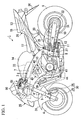
- FIG. 1 is a side view of a motorcycle showing an embodiment of the present invention;
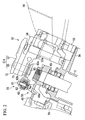
- FIG. 2 is a partially sectioned side view showing the mounting structure of a steering damper in the motorcycle;
- FIG. 3 is a plan view showing the mounting structure of the steering damper in the motorcycle;
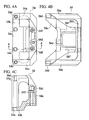
- FIGS. 4A to 4C show a first bracket for steering damper mounting, FIG. 4A is a plan view, FIG. 4B is a side view, and FIG. 4C is a cross-sectional view taken along the line A-A in FIG. 4A;
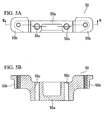
- FIGS. 5A and 5B show a second bracket for steering damper mounting, FIG. 5A is a plan view, and FIG. 5B is a cross-sectional view taken along the line B-B in FIG. 5A;
- FIG. 6 is a cross-cross-sectional view taken along the line C-C in FIG. 3;
- FIG. 7 is a plan view of a steering damper;
- FIG. 8 is a view taken in the direction of the arrow D in FIG. 7;
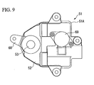
- FIG. 9 is a bottom view of the steering damper;
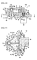
- FIG. 10 is a cross-sectional view of the steering damper;
- FIG. 11 is a partial cross-sectional plan view of a housing body of the steering damper;
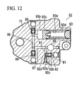
- FIG. 12 is a cross-sectional view taken along the line E-E in FIG. 10;
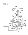
- FIG. 13 is a schematic diagram of the steering damper; and
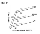
- FIG. 14 is a graph showing the characteristics of the steering damper.
-
- A motorcycle equipped with a steering damper according to the present invention will be explained below with reference to the appended drawings. In the following description, the denotations of the back and front, and right and left directions are defined based on the motorcycle body.
- As shown in FIG. 1, a motorcycle 1 is provided with a motorcycle body frame 2 in the approximate center, and a
front fork 5 which supports a front wheel 4 is steerably supported through a steering stem 6 by a head pipe 3 which is provided in the front end of a motorcycle body frame 2. Amain frame 7 is provided from the head pipe 3 of the motorcycle body frame 2 so as to extend obliquely behind and downward after being separated to the right and left, and to extend downwardly through bends.Pivot sections 8 are provided in the approximately central front end sections of the parts of themain frame 7 extending downward, andrear forks 10 supporting a rear wheel 9 are supported rockably by thepivot sections 8. In addition, slightly rear sections of the parts supported by thepivot sections 8 of therear forks 10 are joined to themain frame 7 throughrear cushions 11 andlink sections 12. - A
seat frame 13 is joined to rear sections of themain frame 7. Afuel tank 14 is arranged above themain frame 7, and anengine body 15 of a water-cooled parallel four-cylinder engine is arranged below themain frame 7. From the front part of themain frame 7, engine hangers 16 are extended downwardly, and the engine hangers 16 support theengine body 15 with other junctions for basic engine support which are provided in themain frame 7. - Behind the
fuel tank 14, a rider'sseat 17 and apillion seat 18 are respectively supported by aseat frame 13. In addition, rider'ssteps 19 are attached in the rear sections of thepivot sections 8 of the motorcycle body frame 2, andco-rider's steps 20 are attached in the lower portion of theseat frame 13. Furthermore, a pair of right andleft handles front fork 5 through atop bridge 49. - A front nose section of the motorcycle 1 is covered with a
front cowl 25, and the vicinity of theseat frame 13 is covered by arear cowl 26. In addition, aretractable prop stand 27 is arranged in a lower left side of the motorcycle body frame 2, theprop stand 27 which supports the motorcycle body of the motorcycle 1 in a rising state oblique to a left side. - A
front brake device 30 is constituted by abrake caliper 28 being attached to a bottom end section of thefront fork 5 and abrake rotor 29, corresponding to thebrake caliper 28, being attached to a front wheel 4. In addition, afront fender 31 covering over the front wheel 4 is attached to a bottom end section of thefront fork 5. - A
rear sprocket 32 is attached to a left side of a rear wheel 9 so as to rotate with the rear wheel 9 integrally. Adrive chain 34 is looped over therear sprocket 32 and adrive sprocket 33 arranged in a lower left side of theengine body 15. Then, a driving force of theengine body 15 is transmitted to the rear wheel 9. A frontrear fender 35 covering over an upper front side of therear fork 10 is attached to an upper portion of the rear wheel 9, and arear fender 36 covering over an upper rear side of the rear wheel 9 is attached to a lower portion of therear cowl 26. In addition, a rear brake device which has the same structure as thefront brake device 30 of the front wheel 4 is provided in therear frame 10. - A
cylinder body 40 of theengine body 15 is arranged so as to slightly incline forward over acrankcase 41.Throttle bodies 42 corresponding to respective cylinders are joined to rear sections of thecylinder body 40, andrespective throttle bodies 42 are joined to an air cleaner case 43 located between themain frame 7 andfuel tank 14. In addition,exhaust pipes 44 corresponding to respective cylinders are joined to front parts of thecylinder body 40. Theexhaust pipes 44 extend forward from a front wall 45 of thecylinder body 40, are curved and extend downwardly, extend in front of and under thecrankcase 41, and extend to a location behind theengine body 15. - The above-mentioned steering stem 6, a
top bridge 49 located above a bottom bridge of the steering stem 6 in parallel to the bottom bridge, thesteering handle 21, and the like constitute thesteering system 50 which steers the front wheel 4. Thesteering system 50 is provided with the steering damper 51 (refer to FIGS. 2 and 3). - The steering
damper 51 is for decreasing the vibration of the steering handle 21 which is caused by a kickback, etc., or absorbing vibration in a low steering angular velocity region which is caused by road surface disturbances during high speed driving. In general, two types of steering dampers are known, one is a rod type and the other is a rotary type, and a rotarytype steering damper 51, which is suitable for reducing the size thereof, is used in this embodiment. - As shown in FIG. 2, the steering
damper 51 includes a steering dampermain body 51 A being constituted by ahousing 52 and ashaft 53 which penetrates a bottom face section of thehousing 52 and protruding outside, and apressure control valve 68 intermediately installed in the fluid path of the steering dampermain body 51A. Thehousing 52 is attached to ajunction 3a provided with extending behind with the head pipe 3 through first andsecond brackets shaft 53 is attached to thetop bridge 49 through alink mechanism 56. - As shown in FIG. 4, the
first bracket 54 has an approximately enclosed type shape whose inside is scooped out, and has right and leftside wall sections bottom plate section 54b, and aleg section 54c which has an approximately Y shape and is connected to rear edge sections of theside plate section 54a, andbottom plate section 54b. Then, respective mountingholes side wall sections leg section 54c, and the above-mentionedsteering damper 51 is bolted through the mountingholes 54d. In addition, mountingholes bottom plate section 54b, and mountingholes leg section 54c respectively, and thefirst bracket 54 is bolted to thejunction 3a of the head pipe 3 through the mountingholes 54e. - As shown in FIG. 5, the
second bracket 55 has abase 55a formed in an approximately rectangular parallelepiped shape, and right and leftoverhang sections holes base 55a so as to be coaxial with the mountingholes first bracket 54. Then, one bolt is inserted into the mountingholes first bracket 54 andsecond bracket 55 are stacked. With the bolt, thesecond bracket 55 is attached to thejunction 3a of the above-mentioned head pipe 3 with thefirst bracket 54. - As for the
link mechanism 56, as shown in FIGS. 2, 3 and 6, anend section 60a of anarm 60 is attached to ashaft 53 which protrudes under the steering dampermain body 51 A. An end section of an elongated figure-8-shape linkage 63 is spherically supported by anotherend section 60b of thearm 60, which is branched into two, through abolt 61, aball member 62 fitted on the outer periphery of thebolt 61, and the like. In addition, another end section of thelinkage 63 is spherically supported by ajunction 49a, formed in thetop bridge 49, through abolt 64 and aball member 65 fitted on the outer periphery of thebolt 64. That is, thelink mechanism 56 which transmits a motion of the top bridge to theshaft 53 is constituted by thearm 60,bolts ball members linkage 63. - Through the above-described first and
second brackets housing 52 of the steering dampermain body 51 A is attached in thetop bridge 49 so as to extend backward. Then, alinear solenoid 69 which drives and controls apressure control valve 68 is located below anextruding section 52a extending from thetop bridge 49 of thehousing 52 backward. - In order to avoid interference with the steering
damper 51 and the first andsecond brackets concavity 14a is formed in the front part of thefuel tank 14. In addition, in FIG. 2,reference numeral 70 denotes an ignition switch located ahead of the head pipe 3. - As shown in FIGS. 7 to 9 and FIG. 11, the
housing 52 of the steering dampermain body 51 A is constituted by abody 71 and acap 72. A fan-like concavity 73 is formed in a top face section of thebody 71, and afluid chamber 74 is formed by theconcavity 73 being covered by thecap 72. Thefluid chamber 74 is partitioned by avane 75 into two, right and left,fluid chambers base 75a of thevane 75 is formed in a cylindrical shape, and theshaft 53 is joined with the cylindrical section in a fixed state so as to rotate integrally with thevane 75 through fixing means such as a spline. Thevane 75 is supported by theshaft 53 in a rockable manner with respect to thehousing 52. - A
groove 75b is continuously formed on a top end, on a bottom end, and on a rear end of thevane 75, each of which faces the inner circumferential surface of thefluid chamber 74. In addition, a sealingmember 76, which is formed in a U-shape so as to match the shape of thegroove 75b, is fitted in thegroove 75b. Thegroove 75b and sealingmember 76 do not reach theshaft 53, but thegroove 75b is formed, and the sealingmember 76 is fitted in thegroove 75b, up to points separated from theshaft 53. - As shown in FIG. 10, in the outer periphery of the
shaft 53,washers base 75a of thevane 75. Furthermore, portions of the outer peripheries ofwashers member 76. In other words, twofluid chambers housing 52 are maintained to be sealed from each other in a fluid-tight manner, and are also maintained to be sealed from theshaft 53 in a fluid-tight manner, by the sealingmember 76 andwashers - A
bushing 78 is fitted on an upper part of an area where thewasher 77a for the sealing of theshaft 53 is fitted, and acirclip 79 is fitted on a lower part of an area where thewasher 77a for sealing is fitted, respectively. In addition, abushing 80 and anoil seal 81 are fitted on a lower part of an area where thewasher 77b for the sealing of the lower side of theshaft 53 is fitted, respectively. - As shown in FIGS. 10 to 12, the
fluid paths fluid chambers body 71 of the above-mentionedhousing 52 so that they extend back further from rear edges of inner circumferential surfaces of thefluid chambers valves fluid paths fluid paths fluid path 86 which makes thefluid paths fluid paths fluid path 86 is joined to afluid path 87 in a lower side, extending so as to be substantially orthogonal to thefluid path 86, through thepressure control valve 68 located in the vertical direction (refer to FIG. 12). Thefluid path 87 extends forward from an area in which thepressure control valve 68 is provided so as to reach under thefluid chamber 74, and communicates with thefluid path 88 whose front end is approximately orthogonal to thefluid path 87. Near both right and left end sections of thefluid path 88,check valves fluid path 87 rise upward and communicate with the above-mentioned right and leftfluid chambers fluid path 88 acts as a fluid path in an entrance side to which the once exhausted hydraulic fluid is returned again to thefluid chambers fluid path 87 where the above-mentioned electricpressure control valve 68 is intermediately installed becomes a connecting fluid path which makes the fluid paths in the entrance side and discharge side in view of the fluid chamber communicate. Thefluid paths body 7 of thehousing 52. - Both the
check valves check valve 85 as an example, in avalve body 85a, not only avalve seat 85b is provided, but also aball 85c is contained. Theball 85c is suitably urged by aspring 85d so as to abut against thevalve seat 85b. While allowing fluid to flow in the direction of separating theball 85c from thevalve seat 85b with resisting an urging force of thespring 85d, thecheck valve 85 prevents the flow of the fluid in the reverse direction. While allowing hydraulic fluid to flow toward thefluid path 86 through thefluid paths fluid chambers check valve 85 prevents the flow of the hydraulic fluid in the reverse direction. In addition, while allowing hydraulic fluid to return toward thefluid chambers fluid path 88, thecheck valve 89 prevents the flow of the hydraulic fluid in the reverse direction. - As shown in FIG. 10, the
pressure control valve 68 varies a damping force of thesteering damper 51. As for thepressure control valve 68, not only is avalve seat 68b provided in avalve body 68a, but also apoppet 68c is contained so as to face thevalve seat 68b. Thepoppet 68c is suitably urged by aspring 68d intermediately installed between a base spring seat of thepoppet 68c, and thevalve seat 68b so as to depart from thevalve seat 68b. An upper end of apush rod 68e is inserted into a lower edge of thepoppet 68c, and a lower edge of thepush rod 68e is joined to thelinear solenoid 69. Then, pressure adjustment is performed by the energizing operation of thelinear solenoid 69 so that thepoppet 68c may resist the urging force of thespring 68d for its head to abut against thevalve seat 68c. - According to the
pressure control valve 68, a location of thepoppet 68c is settled by the differential pressure between the right and leftfluid chambers housing 52 which communicate with spaces of its head and base, the urging force of thespring 68d, and an exciting force of thelinear solenoid 69 through thepush rod 68e. When a resultant force of the poppet thrust, based on the differential pressure between the right and leftfluid chambers spring 68d is weaker than the exciting force of thelinear solenoid 69, thepoppet 68c abuts on thevalve seat 68b for thepressure control valve 68 concerned to be in a closed state. On the other hand, when the resultant force of the poppet thrust, based on the differential pressure between of the right and leftfluid chambers spring 68d exceeds the exciting force of thelinear solenoid 69, thepoppet 68c depart from thevalve seat 68b for thepressure control valve 68 to be in an open state. Then, it is made that a predetermined damping force is obtained when hydraulic fluid passes through a gap between thevalve seat 68b andpoppet 68c of thepressure control valve 68. - In addition, the
linear solenoid 69 is controlled by a controller, which is not illustrated, according to vehicle speed or vehicle body acceleration. - As shown in FIG. 12, a
bypass fluid path 91 is formed between thefluid path 86 andfluid path 87, and arelief valve 92 is intermediately installed in thebypass fluid path 91. Therelief valve 92 has the structure that not only avalve seat 92b is provided in a valve body 92a, but also aball 92c is contained, theball 92c which is energized toward thevalve seat 92b with the suitable thrust by the spring 92d. Then, usually, although theball 92c is abutting on thevalve seat 92b, therelief valve 92 is moved and opens the valve by theball 92c departing from a valve seat with resisting the urging force of the spring 92d by the thrust based on the differential pressure when the differential pressure between thefluid path 86 andfluid path 87 becomes a predetermined value or higher. Accordingly, the differential pressure between thefluid path 86 andfluid path 87 is relieved. - In addition, a
free piston 93 communicates with thefluid path 88. Thefree piston 93 has the structure of including acylinder 93a formed with thebody 71 integrally, apiston 93c which partitions a reservingsection 93b for reserving hydraulic fluid in a front part of thecylinder 93a, and aspring 93d which energizes thepiston 93c toward the reserving section. Then, in thefree piston 93, when the hydraulic fluid filled in a closed space which is constituted by the above-mentioned fluid chambers74a and 74b,fluid paths section 93b changes because of the movement of thepiston 93c to absorb the thermal expansion of the hydraulic fluid, etc. - Next, the operations of the steering damper having the above-mentioned structure will be explained below.
- When a main switch of the vehicle is turned ON, the controller which controls the steering
damper 51 starts. Thelinear solenoid 69 which controls thehydraulic control valve 68 of thesteering damper 51 is controlled according to the vehicle speed and vehicle body acceleration which are determined by sensors, not shown, respectively. - When the steering handle 21 is turned to the left during driving, the
top bridge 49 rotates in this direction integrally with thesteering handle 21, and the motion of thetop bridge 49 is transmitted to theshaft 53 of the steering dampermain body 51 A through thelink mechanism 56. As shown in FIG. 11, when theshaft 53 rotates counterclockwise, thevane 75 also rotates in this direction therewith (F direction in FIG. 11). In connection with this, while the pressure of the hydraulic fluid, which is filled in thefluid chamber 74b, increases, since thefluid chamber 74b becomes narrow, the hydraulic fluid in thefluid chamber 74b directly moves to thefluid chamber 74a in another side through a gap between thevane 75 and inner circumferential surface which partitions thefluid chamber 74, and the like (indicated by symbol (a) in FIG. 14). When the pressure of the hydraulic fluid in thefluid chamber 74b, which becomes narrow, increase still further although some hydraulic fluid directly moves to thefluid chamber 74a from thefluid chamber 74b, the hydraulic fluid reaches thefluid path 86 through thefluid path 84 andcheck valve 85, and tries to reach the pressure control valve 6 therefrom. - Because the
poppet 68c usually abuts against thevalve seat 68b by the exciting force of thelinear solenoid 69, thepressure control valve 68 is closed. Accordingly, even if some hydraulic fluid pressure is applied from thefluid chamber 74b, thepressure control valve 68 is maintained in the closed state. Because the thrust based on the differential pressure between the right and leftfluid chambers steering handle 21, the resultant force of the thrust and urging force of thespring 68d may exceed the exciting force of thelinear solenoid 69. In this case, thepoppet 68c departs from avalve seat 68b, and hence, thepressure control valve 68 becomes in the open state (this point is indicated by each symbol (b) in FIG. 14). Then, through thepressure control valve 68 which becomes in the open state, the hydraulic fluid in thefluid path 86 passes along a gap between thevalve seat 68b of thepressure control valve 68 and thepoppet 68c, and reaches thefluid path 87. Furthermore, it reaches therefrom to theleft fluid chamber 74a through thefluid path 88 and check valve 89 (indicated by each symbol (c) in FIG. 14). That is, the hydraulic fluid flows into thefluid chamber 74a continuously from thefluid chamber 74b through thepressure control valve 68 which become in the open state. - The flow resistance of the hydraulic fluid which flows into the
fluid chamber 74a from thefluid chamber 74b generates a damping force which acts on thesteering handle 21. In other words, the flow resistance of the hydraulic fluid acts as a resistance force when turning thesteering handle 21, and acts as a resistance force to the momentary turning force acting on the steering handle. - In the example shown in FIG. 14, three typical cases are shown, in which electrical current supplied to the
linear solenoid 69 is set at three typical points, i.e., at high, medium, and low. In either cases, the increasing rate of the damping force with respect to the steering angular velocity after thepressure control valve 68 once becoming in the open state is set to be low when compared with the case in which thepressure control valve 68 is in the closed state, even though the damping forces when thepressure control valve 68 is in the open state change depending on electrical current values. - More specifically, with each of the positions indicated by symbols (b) in FIG. 14 as a boundary point, the increasing rate of the damping force with respect to the steering angular velocity become smaller at a large steering angular velocity than at a small steering angular velocity, or at a large damping force than at a low damping force (i.e., the slope of line (c) in FIG. 14 becomes less than the slope of line (a)).
- This can be explained as follows. Since the hydraulic fluid flows through a very narrow gap between the
vane 75 and inner circumferential surface which partitions thefluid chamber 74, or the like until thepressure control valve 68 opens when the hydraulic fluid flows from onefluid chamber 74b to anotherfluid chamber 74a, flow resistance is relatively large. Nevertheless, since the flow resistance becomes small because the hydraulic fluid mainly flows through the passage of the openpressure control valve 68 after thepressure control valve 68 is opened, this emerges as the increasing rate of the damping force with respect to the steering angular velocity. - In consequence, it is possible to quickly increase the damping force as the steering angular velocity becomes large even if the damping force is small when the steering angular velocity is small. Accordingly, it is possible to concurrently solve two problems of making the starting torque of the steering handle 21 small and absorbing the vibration in the low steering angular velocity region which is caused by road surface disturbances during medium speed driving or high speed driving. In addition, because the increasing rate of the damping force is set to be low when the steering angular velocity exceeds each of positions (b) as the boundary point, it is possible to prevent the damping force from exceeding a predetermined value. Accordingly, it is possible to prevent the effort of handling from becoming too great beyond a predetermined value.
- In addition, as described above, the
linear solenoid 69 is controlled depending on the vehicle speed. More specifically, the upper limit of the current supplied to thelinear solenoid 69 is controlled so as to be high as vehicle speed is increased. Hence, for example, at a high-speed region, the timing when thepressure control valve 68 enters in the open state (each symbol (b) in FIG. 14) is delayed, and furthermore, a larger damping force is exhibited by an increased amount of the exciting force even after entering in the open state. That is, when vehicle speed reaches a high-speed region, a damping force larger than that in a low speed region or a medium speed region is exhibited. Accordingly, since handling ability is considered to be important at low speed driving, it is possible to turn the steering handle 21 with a relatively small force. On the other hand, since a high damping force acts when turning the steering handle 21 during high speed driving, it is possible to further absorb the vibrations in a low steering angular velocity region which is caused by road surface disturbances during high speed driving. - Although in the above description, the case in which the steering handle 21 is turned to the left is explained; however, the same description applies to the case in which the steering handle 21 is turned to the right.
- In addition, the hydraulic fluid pressure in one of the right and left
fluid chambers steering damper 51, and thus the differential pressure of the hydraulic fluid between the upstream and downstream of thepressure control valve 68 may become larger than a preset value, the excessively large differential pressure between them is relieved by opening therelief valve 92 so as to allow the hydraulic fluid in thefluid path 86 to flow to thefluid path 87 through thebypass fluid path 91. In this manner, the hydraulic fluid pressure of the one fluid chamber becoming excessively high is prevented beforehand. - In addition, when the temperature of the hydraulic fluid filled in the
fluid chamber 74 andfluid paths piston 93c of thefree piston 93 moves inside thecylinder 93a according to it. - While preferred embodiments of the invention have been described and illustrated above, it should be understood that these are exemplary of the invention and are not to be considered as limiting. Additions, omissions, substitutions, and other modifications can be made without departing from the spirit or scope of the present invention.
- For example, in the above-mentioned embodiment, the current value supplied to the
linear solenoid 69 is controlled steplessly according to the vehicle speed and vehicle body acceleration (in addition, FIG. 14 shows only three typical cases, that is, high, medium, and low current for the convenience of expression). The present invention is not limited to this, and can be applied to a configuration in which the supply current value to thelinear solenoid 69 is controlled stepwise. - Moreover, in the above-mentioned embodiment, it is made to change the damping force of the
steering damper 51 through thepressure control valve 68 controlled by thelinear solenoid 69. The present invention is not limited to this, and it is also possible for the relationship between the steering angular velocity and the damping force of the steering system to not be linear over the entire steering angular velocity region by therelief valve 92 provided in the fluid path communicating with thefluid path 88 in an entrance side to thefluid chamber 74 of the steering dampermain body 51 A, andfluid paths - As mentioned above in detail, according to the steering damper of the present invention, the relationship between the steering angular velocity and the damping force of the steering system is not linear in a full steering angular velocity region. However, the steering damper is set so that an increasing rate of the damping force with respect to the steering angular velocity of the steering system may become smaller at a large steering angular velocity than at a small steering angular velocity, or at a large damping force than at a small damping force. Hence, it is possible to quickly increase the damping force as the steering angular velocity becomes large even if the damping force is small when the steering angular velocity is small. Owing to this, it is possible to concurrently solve two problems of making the starting torque of a steering handle small and absorbing the vibration in the low steering angular velocity region which is caused by road surface disturbance during high speed driving. In addition, since the increasing rate of the damping force becomes gentle even if the steering angular velocity becomes large after that, it is possible to prevent the damping force from rising to a predetermined value or larger.
- The invention is not to be considered as being limited by the foregoing description, and is only limited by the scope of the appended claims.
- A steering damper includes a steering damper body installed in a steering system of a vehicle, and having a fluid path therein, and a pressure control valve for controlling a damping force in the steering system, and provided in the fluid path, wherein the pressure control valve controls the damping force so that an increasing rate of the damping force with respect to a steering angular velocity when the steering angular velocity is large is lower than that when the steering angular velocity is small.
Claims (6)
- A steering damper comprising:wherein the pressure control valve controls the damping force so that an increasing rate of the damping force with respect to a steering angular velocity when the steering angular velocity is larger is lower than that when the steering angular velocity is small.a steering damper body installed in a steering system of a vehicle, and having a fluid path therein; anda pressure control valve for controlling a damping force in the steering system, and provided in the fluid path,
- A steering damper according to claim 1, wherein the pressure control valve controls the damping force so that the increasing rate of the damping force with respect to the steering angular velocity when the steering angular velocity is larger than a predetermined value is lower than that when the steering angular velocity is smaller than or equal to the predetermined value.
- A steering damper according to claim 1,
wherein the steering damper body comprises a fluid chamber having an entrance and an exit, a first fluid path connected to the entrance of the fluid chamber, a second fluid path connected to the exit of the fluid chamber, and a connection fluid path connecting the first fluid path to the second fluid path, and
wherein the pressure control valve is a relief valve provided in the connection fluid path. - A steering damper comprising:wherein the pressure control valve controls the damping force so that an increasing rate of the damping force with respect to a steering angular velocity when the damping force is large is lower than that when the damping force is small.a steering damper body installed in a steering system of a vehicle, and having a fluid path therein; anda pressure control valve for controlling a damping force in the steering system, and provided in the fluid path,
- A steering damper according to claim 4, wherein the pressure control valve controls the damping force so that the increasing rate of the damping force with respect to the steering angular velocity when the damping force is larger than a predetermined value is lower than that when the damping force is smaller than or equal to the predetermined value.
- A steering damper according to claim 4,
wherein the steering damper body comprises a fluid chamber having an entrance and an exit, a first fluid path connected to the entrance of the fluid chamber, a second fluid path connected to the exit of the fluid chamber, and a connection fluid path connecting the first fluid path to the second fluid path, and
wherein the pressure control valve is a relief valve provided in the connection fluid path.
Applications Claiming Priority (2)
| Application Number | Priority Date | Filing Date | Title |
|---|---|---|---|
| JP2003151263A JP4545392B2 (en) | 2003-05-28 | 2003-05-28 | Steering damper |
| JP2003151263 | 2003-05-28 |
Publications (3)
| Publication Number | Publication Date |
|---|---|
| EP1481882A2 true EP1481882A2 (en) | 2004-12-01 |
| EP1481882A3 EP1481882A3 (en) | 2007-07-18 |
| EP1481882B1 EP1481882B1 (en) | 2011-08-10 |
Family
ID=33128253
Family Applications (1)
| Application Number | Title | Priority Date | Filing Date |
|---|---|---|---|
| EP04012506A Expired - Lifetime EP1481882B1 (en) | 2003-05-28 | 2004-05-26 | Steering damper |
Country Status (4)
| Country | Link |
|---|---|
| US (1) | US7267350B2 (en) |
| EP (1) | EP1481882B1 (en) |
| JP (1) | JP4545392B2 (en) |
| ES (1) | ES2367792T3 (en) |
Cited By (5)
| Publication number | Priority date | Publication date | Assignee | Title |
|---|---|---|---|---|
| DE102006036135A1 (en) * | 2006-08-01 | 2008-02-07 | Edgar Uden | Steering damper for e.g. motor vehicle, has check valves obtaining modulated variables, where effectiveness of damper is changed based on horizontal acceleration in area of steering mechanism and/or driven wheels or steered wheels |
| EP2130754A1 (en) * | 2008-06-04 | 2009-12-09 | Yamaha Hatsudoki Kabushiki Kaisha | Steering damper system, and a saddle riding type vehicle having the same |
| ITMI20090904A1 (en) * | 2009-05-21 | 2010-11-22 | Piaggio & C Spa | METHOD OF CONTROL OF AN ELECTRONICALLY MODULAR STEERING DAMPER FOR A TWO-WHEEL VEHICLE AND EQUIPMENT IMPLEMENTING THE SAME |
| EP2167837A4 (en) * | 2007-06-14 | 2014-05-14 | Hlins Racing Ab | Hydraulic rotary damper for vehicle |
| US9409588B2 (en) | 2011-05-05 | 2016-08-09 | Ohlins Racing Ab | Steering damper with active adjustment of damping characteristics |
Families Citing this family (14)
| Publication number | Priority date | Publication date | Assignee | Title |
|---|---|---|---|---|
| US7021433B2 (en) * | 2003-03-20 | 2006-04-04 | Honda Motor Co., Ltd. | Vehicle steering damper, steering damper kit for motorcycle, and motorcycle incorporating same |
| JP4493074B2 (en) * | 2004-02-05 | 2010-06-30 | 本田技研工業株式会社 | Steering damper device for motorcycles |
| JP2006226342A (en) * | 2005-02-16 | 2006-08-31 | Kayaba Ind Co Ltd | Valve structure |
| JP4545624B2 (en) * | 2005-03-31 | 2010-09-15 | 本田技研工業株式会社 | Steering damper mounting structure |
| JP4768462B2 (en) * | 2006-02-06 | 2011-09-07 | カヤバ工業株式会社 | Rotary damper |
| JP4739969B2 (en) * | 2006-02-06 | 2011-08-03 | カヤバ工業株式会社 | Rotary damper |
| JP4750571B2 (en) * | 2006-02-15 | 2011-08-17 | カヤバ工業株式会社 | Rotary damper |
| US7793957B2 (en) * | 2007-06-29 | 2010-09-14 | Kayaba Industry Co., Ltd. | Steering damping device |
| US7970511B2 (en) * | 2008-02-06 | 2011-06-28 | Honda Motor Company, Ltd. | Electronic steering damper systems and vehicles including same |
| US9863450B1 (en) * | 2014-04-16 | 2018-01-09 | Rockwell Collins, Inc. | Hydro-mechanical device with preloaded flow regulating assembly |
| IT201600090140A1 (en) * | 2016-09-06 | 2018-03-06 | Piaggio & C Spa | STEERING GROUP OF MOTORCYCLE AND ITS MOTORCYCLE |
| US10946925B2 (en) * | 2017-12-14 | 2021-03-16 | George John Athanasiou | Multi positional rotary steering damper assembly |
| JP2021162368A (en) | 2020-03-30 | 2021-10-11 | 株式会社豊田中央研究所 | Tire condition estimation device, tire condition estimation method and tire condition estimation program |
| CN119636979A (en) * | 2025-02-13 | 2025-03-18 | 隆鑫通用动力股份有限公司 | Electronic steering damper, steering control system, method and vehicle |
Citations (5)
| Publication number | Priority date | Publication date | Assignee | Title |
|---|---|---|---|---|
| JPH0774023B2 (en) | 1986-07-01 | 1995-08-09 | カヤバ工業株式会社 | Damping force control device for steering damper of motorcycle |
| US5944152A (en) | 1993-10-14 | 1999-08-31 | Vitec Group, Plc | Apparatus mountings providing at least one axis of movement with damping |
| EP1248013A2 (en) | 2001-04-06 | 2002-10-09 | Honda Giken Kogyo Kabushiki Kaisha | Steering damper system |
| EP1323625A2 (en) | 2001-12-28 | 2003-07-02 | Honda Giken Kogyo Kabushiki Kaisha | Steering damper system |
| EP1459971A2 (en) | 2003-03-20 | 2004-09-22 | HONDA MOTOR CO., Ltd. | Vehicle steering damper |
Family Cites Families (8)
| Publication number | Priority date | Publication date | Assignee | Title |
|---|---|---|---|---|
| US3907079A (en) * | 1973-10-31 | 1975-09-23 | Hughes Aircraft Co | Viscous fluid damper |
| JPS60219183A (en) * | 1984-04-13 | 1985-11-01 | ヤマハ発動機株式会社 | Steering gear for motorcycle |
| JPH0322586Y2 (en) * | 1985-02-23 | 1991-05-16 | ||
| JPH03239828A (en) * | 1990-02-13 | 1991-10-25 | Kayaba Ind Co Ltd | Rotary damper |
| WO1994006672A1 (en) * | 1992-09-18 | 1994-03-31 | Klein Bicycle Corporation | A high efficiency bicycle suspension |
| JPH0774023A (en) | 1993-09-01 | 1995-03-17 | Hitachi Ltd | Integrated inductor and surface acoustic wave device using the same |
| JP4640904B2 (en) * | 2001-09-07 | 2011-03-02 | 本田技研工業株式会社 | Steering damper device |
| US6802519B2 (en) * | 2002-09-09 | 2004-10-12 | Rtt Motorsports, Llc | Steering damper |
-
2003
- 2003-05-28 JP JP2003151263A patent/JP4545392B2/en not_active Expired - Lifetime
-
2004
- 2004-05-25 US US10/853,847 patent/US7267350B2/en not_active Expired - Lifetime
- 2004-05-26 ES ES04012506T patent/ES2367792T3/en not_active Expired - Lifetime
- 2004-05-26 EP EP04012506A patent/EP1481882B1/en not_active Expired - Lifetime
Patent Citations (5)
| Publication number | Priority date | Publication date | Assignee | Title |
|---|---|---|---|---|
| JPH0774023B2 (en) | 1986-07-01 | 1995-08-09 | カヤバ工業株式会社 | Damping force control device for steering damper of motorcycle |
| US5944152A (en) | 1993-10-14 | 1999-08-31 | Vitec Group, Plc | Apparatus mountings providing at least one axis of movement with damping |
| EP1248013A2 (en) | 2001-04-06 | 2002-10-09 | Honda Giken Kogyo Kabushiki Kaisha | Steering damper system |
| EP1323625A2 (en) | 2001-12-28 | 2003-07-02 | Honda Giken Kogyo Kabushiki Kaisha | Steering damper system |
| EP1459971A2 (en) | 2003-03-20 | 2004-09-22 | HONDA MOTOR CO., Ltd. | Vehicle steering damper |
Cited By (8)
| Publication number | Priority date | Publication date | Assignee | Title |
|---|---|---|---|---|
| DE102006036135A1 (en) * | 2006-08-01 | 2008-02-07 | Edgar Uden | Steering damper for e.g. motor vehicle, has check valves obtaining modulated variables, where effectiveness of damper is changed based on horizontal acceleration in area of steering mechanism and/or driven wheels or steered wheels |
| DE102006036135B4 (en) * | 2006-08-01 | 2010-07-22 | Edgar Uden | Variable-action steering damper for motor vehicles and other vehicles with only one steered front wheel |
| EP2167837A4 (en) * | 2007-06-14 | 2014-05-14 | Hlins Racing Ab | Hydraulic rotary damper for vehicle |
| EP2130754A1 (en) * | 2008-06-04 | 2009-12-09 | Yamaha Hatsudoki Kabushiki Kaisha | Steering damper system, and a saddle riding type vehicle having the same |
| US8775024B2 (en) | 2008-06-04 | 2014-07-08 | Yamaha Hatsudoki Kabushiki Kaisha | Steering damper system, and a saddle riding type vehicle having the same |
| ITMI20090904A1 (en) * | 2009-05-21 | 2010-11-22 | Piaggio & C Spa | METHOD OF CONTROL OF AN ELECTRONICALLY MODULAR STEERING DAMPER FOR A TWO-WHEEL VEHICLE AND EQUIPMENT IMPLEMENTING THE SAME |
| EP2256022A1 (en) * | 2009-05-21 | 2010-12-01 | PIAGGIO & C. S.p.A. | Method for controlling an electronically adjustable steering damper for a two-wheeled vehicle and apparatus implementing it |
| US9409588B2 (en) | 2011-05-05 | 2016-08-09 | Ohlins Racing Ab | Steering damper with active adjustment of damping characteristics |
Also Published As
| Publication number | Publication date |
|---|---|
| JP4545392B2 (en) | 2010-09-15 |
| ES2367792T3 (en) | 2011-11-08 |
| US20040239069A1 (en) | 2004-12-02 |
| EP1481882B1 (en) | 2011-08-10 |
| JP2004352048A (en) | 2004-12-16 |
| US7267350B2 (en) | 2007-09-11 |
| EP1481882A3 (en) | 2007-07-18 |
Similar Documents
| Publication | Publication Date | Title |
|---|---|---|
| EP1481882B1 (en) | Steering damper | |
| EP1459971B1 (en) | Vehicle steering damper | |
| US7712756B2 (en) | Steering damper mounting structure | |
| JP4640905B2 (en) | Steering damper device | |
| CN1321857C (en) | steering damper unit | |
| US7258211B2 (en) | Rotary damper | |
| JP2003237672A (en) | Steering damper for motorcycle | |
| JP4197592B2 (en) | Steering damper device | |
| EP1323946B1 (en) | Steering damper system | |
| US7559566B2 (en) | Swing arm suspension | |
| JP3836053B2 (en) | Motorcycle frame | |
| JP4342981B2 (en) | Rotary damper | |
| JP4463489B2 (en) | Steering damper mounting structure for motorcycles | |
| JP4342820B2 (en) | Steering damper for vehicles | |
| JP4198497B2 (en) | Steering damper mounting structure for motorcycles | |
| JP2004026092A (en) | Steering damper device for motorcycle | |
| JP2004231036A (en) | Steering device | |
| JP4092144B2 (en) | Steering device | |
| JP4142291B2 (en) | Steering damper device | |
| JP3104573B2 (en) | Suspension arm support structure | |
| JP6494682B2 (en) | Steering damper device for saddle-ride type vehicles | |
| JP2019059328A (en) | Steering damper device for straddle type vehicle |
Legal Events
| Date | Code | Title | Description |
|---|---|---|---|
| PUAI | Public reference made under article 153(3) epc to a published international application that has entered the european phase |
Free format text: ORIGINAL CODE: 0009012 |
|
| AK | Designated contracting states |
Kind code of ref document: A2 Designated state(s): AT BE BG CH CY CZ DE DK EE ES FI FR GB GR HU IE IT LI LU MC NL PL PT RO SE SI SK TR |
|
| AX | Request for extension of the european patent |
Extension state: AL HR LT LV MK |
|
| PUAL | Search report despatched |
Free format text: ORIGINAL CODE: 0009013 |
|
| AK | Designated contracting states |
Kind code of ref document: A3 Designated state(s): AT BE BG CH CY CZ DE DK EE ES FI FR GB GR HU IE IT LI LU MC NL PL PT RO SE SI SK TR |
|
| AX | Request for extension of the european patent |
Extension state: AL HR LT LV MK |
|
| 17P | Request for examination filed |
Effective date: 20071025 |
|
| AKX | Designation fees paid |
Designated state(s): DE ES FR GB IT |
|
| 17Q | First examination report despatched |
Effective date: 20090702 |
|
| GRAP | Despatch of communication of intention to grant a patent |
Free format text: ORIGINAL CODE: EPIDOSNIGR1 |
|
| GRAS | Grant fee paid |
Free format text: ORIGINAL CODE: EPIDOSNIGR3 |
|
| GRAA | (expected) grant |
Free format text: ORIGINAL CODE: 0009210 |
|
| RAP1 | Party data changed (applicant data changed or rights of an application transferred) |
Owner name: KAYABA INDUSTRY CO., LTD. Owner name: HONDA MOTOR CO., LTD. |
|
| RIN1 | Information on inventor provided before grant (corrected) |
Inventor name: SAKAI, KIYOTAKA Inventor name: NANRI, TAKEHIKO Inventor name: WAKABAYASHI, TAKESHI Inventor name: YAMADA, SHINICHI |
|
| AK | Designated contracting states |
Kind code of ref document: B1 Designated state(s): DE ES FR GB IT |
|
| REG | Reference to a national code |
Ref country code: GB Ref legal event code: FG4D |
|
| REG | Reference to a national code |
Ref country code: DE Ref legal event code: R081 Ref document number: 602004033820 Country of ref document: DE Owner name: KYB CORPORATION, JP Free format text: FORMER OWNERS: HONDA MOTOR CO., LTD., TOKYO, JP; KAYABA INDUSTRY CO., LTD., TOKYO, JP Ref country code: DE Ref legal event code: R081 Ref document number: 602004033820 Country of ref document: DE Owner name: HONDA MOTOR CO., LTD., JP Free format text: FORMER OWNERS: HONDA MOTOR CO., LTD., TOKYO, JP; KAYABA INDUSTRY CO., LTD., TOKYO, JP |
|
| REG | Reference to a national code |
Ref country code: DE Ref legal event code: R096 Ref document number: 602004033820 Country of ref document: DE Effective date: 20111013 |
|
| REG | Reference to a national code |
Ref country code: ES Ref legal event code: FG2A Ref document number: 2367792 Country of ref document: ES Kind code of ref document: T3 Effective date: 20111108 |
|
| PG25 | Lapsed in a contracting state [announced via postgrant information from national office to epo] |
Ref country code: IT Free format text: LAPSE BECAUSE OF FAILURE TO SUBMIT A TRANSLATION OF THE DESCRIPTION OR TO PAY THE FEE WITHIN THE PRESCRIBED TIME-LIMIT Effective date: 20110810 |
|
| PLBE | No opposition filed within time limit |
Free format text: ORIGINAL CODE: 0009261 |
|
| STAA | Information on the status of an ep patent application or granted ep patent |
Free format text: STATUS: NO OPPOSITION FILED WITHIN TIME LIMIT |
|
| 26N | No opposition filed |
Effective date: 20120511 |
|
| REG | Reference to a national code |
Ref country code: DE Ref legal event code: R097 Ref document number: 602004033820 Country of ref document: DE Effective date: 20120511 |
|
| REG | Reference to a national code |
Ref country code: FR Ref legal event code: PLFP Year of fee payment: 12 |
|
| REG | Reference to a national code |
Ref country code: DE Ref legal event code: R082 Ref document number: 602004033820 Country of ref document: DE Representative=s name: WEICKMANN & WEICKMANN PATENTANWAELTE - RECHTSA, DE Ref country code: DE Ref legal event code: R081 Ref document number: 602004033820 Country of ref document: DE Owner name: HONDA MOTOR CO., LTD., JP Free format text: FORMER OWNERS: HONDA MOTOR CO., LTD., TOKYO, JP; KAYABA INDUSTRY CO., LTD., TOKYO, JP Ref country code: DE Ref legal event code: R081 Ref document number: 602004033820 Country of ref document: DE Owner name: KYB CORPORATION, JP Free format text: FORMER OWNERS: HONDA MOTOR CO., LTD., TOKYO, JP; KAYABA INDUSTRY CO., LTD., TOKYO, JP Ref country code: DE Ref legal event code: R082 Ref document number: 602004033820 Country of ref document: DE Representative=s name: WEICKMANN & WEICKMANN PATENT- UND RECHTSANWAEL, DE |
|
| REG | Reference to a national code |
Ref country code: ES Ref legal event code: PC2A Owner name: KYB CORPORATION Effective date: 20160226 |
|
| REG | Reference to a national code |
Ref country code: FR Ref legal event code: PLFP Year of fee payment: 13 |
|
| REG | Reference to a national code |
Ref country code: FR Ref legal event code: CD Owner name: KYB CORPORATION, JP Effective date: 20160321 Ref country code: FR Ref legal event code: CD Owner name: HONDA MOTOR CO., LTD., JP Effective date: 20160321 Ref country code: FR Ref legal event code: CA Effective date: 20160321 |
|
| PG25 | Lapsed in a contracting state [announced via postgrant information from national office to epo] |
Ref country code: IT Free format text: LAPSE BECAUSE OF FAILURE TO SUBMIT A TRANSLATION OF THE DESCRIPTION OR TO PAY THE FEE WITHIN THE PRESCRIBED TIME-LIMIT Effective date: 20120526 |
|
| PG25 | Lapsed in a contracting state [announced via postgrant information from national office to epo] |
Ref country code: IT Free format text: LAPSE BECAUSE OF FAILURE TO SUBMIT A TRANSLATION OF THE DESCRIPTION OR TO PAY THE FEE WITHIN THE PRESCRIBED TIME-LIMIT Effective date: 20120526 |
|
| PGRI | Patent reinstated in contracting state [announced from national office to epo] |
Ref country code: IT Effective date: 20161116 |
|
| REG | Reference to a national code |
Ref country code: FR Ref legal event code: PLFP Year of fee payment: 14 |
|
| REG | Reference to a national code |
Ref country code: FR Ref legal event code: PLFP Year of fee payment: 15 |
|
| PGFP | Annual fee paid to national office [announced via postgrant information from national office to epo] |
Ref country code: SE Payment date: 20190523 Year of fee payment: 18 Ref country code: ES Payment date: 20190604 Year of fee payment: 16 |
|
| PGFP | Annual fee paid to national office [announced via postgrant information from national office to epo] |
Ref country code: FR Payment date: 20190410 Year of fee payment: 16 |
|
| PGFP | Annual fee paid to national office [announced via postgrant information from national office to epo] |
Ref country code: GB Payment date: 20190522 Year of fee payment: 16 |
|
| GBPC | Gb: european patent ceased through non-payment of renewal fee |
Effective date: 20200526 |
|
| PG25 | Lapsed in a contracting state [announced via postgrant information from national office to epo] |
Ref country code: GB Free format text: LAPSE BECAUSE OF NON-PAYMENT OF DUE FEES Effective date: 20200526 Ref country code: FR Free format text: LAPSE BECAUSE OF NON-PAYMENT OF DUE FEES Effective date: 20200531 |
|
| REG | Reference to a national code |
Ref country code: DE Ref legal event code: R082 Ref document number: 602004033820 Country of ref document: DE Representative=s name: WEICKMANN & WEICKMANN PATENT- UND RECHTSANWAEL, DE Ref country code: DE Ref legal event code: R081 Ref document number: 602004033820 Country of ref document: DE Owner name: HONDA MOTOR CO., LTD., JP Free format text: FORMER OWNERS: HONDA MOTOR CO., LTD., TOKYO, JP; KYB CORPORATION, TOKIO, JP |
|
| PGFP | Annual fee paid to national office [announced via postgrant information from national office to epo] |
Ref country code: DE Payment date: 20210427 Year of fee payment: 18 |
|
| REG | Reference to a national code |
Ref country code: ES Ref legal event code: FD2A Effective date: 20211004 |
|
| PG25 | Lapsed in a contracting state [announced via postgrant information from national office to epo] |
Ref country code: ES Free format text: LAPSE BECAUSE OF NON-PAYMENT OF DUE FEES Effective date: 20200527 |
|
| REG | Reference to a national code |
Ref country code: DE Ref legal event code: R119 Ref document number: 602004033820 Country of ref document: DE |
|
| PG25 | Lapsed in a contracting state [announced via postgrant information from national office to epo] |
Ref country code: IT Free format text: LAPSE BECAUSE OF FAILURE TO SUBMIT A TRANSLATION OF THE DESCRIPTION OR TO PAY THE FEE WITHIN THE PRESCRIBED TIME-LIMIT Effective date: 20200526 |
|
| PG25 | Lapsed in a contracting state [announced via postgrant information from national office to epo] |
Ref country code: DE Free format text: LAPSE BECAUSE OF NON-PAYMENT OF DUE FEES Effective date: 20221201 |