EP1481855B1 - Luftsackhalter - Google Patents
Luftsackhalter Download PDFInfo
- Publication number
- EP1481855B1 EP1481855B1 EP03011864A EP03011864A EP1481855B1 EP 1481855 B1 EP1481855 B1 EP 1481855B1 EP 03011864 A EP03011864 A EP 03011864A EP 03011864 A EP03011864 A EP 03011864A EP 1481855 B1 EP1481855 B1 EP 1481855B1
- Authority
- EP
- European Patent Office
- Prior art keywords
- airbag
- holder
- holding chamber
- air bag
- container wall
- Prior art date
- Legal status (The legal status is an assumption and is not a legal conclusion. Google has not performed a legal analysis and makes no representation as to the accuracy of the status listed.)
- Expired - Lifetime
Links
- 239000000463 material Substances 0.000 claims description 9
- 238000005192 partition Methods 0.000 claims description 7
- 239000012528 membrane Substances 0.000 claims description 5
- 239000004744 fabric Substances 0.000 description 5
- 230000004308 accommodation Effects 0.000 description 3
- 238000009434 installation Methods 0.000 description 3
- 239000011888 foil Substances 0.000 description 1
- 230000002093 peripheral effect Effects 0.000 description 1
- 230000001681 protective effect Effects 0.000 description 1
Images

Classifications
-
- B—PERFORMING OPERATIONS; TRANSPORTING
- B60—VEHICLES IN GENERAL
- B60R—VEHICLES, VEHICLE FITTINGS, OR VEHICLE PARTS, NOT OTHERWISE PROVIDED FOR
- B60R21/00—Arrangements or fittings on vehicles for protecting or preventing injuries to occupants or pedestrians in case of accidents or other traffic risks
- B60R21/02—Occupant safety arrangements or fittings, e.g. crash pads
- B60R21/16—Inflatable occupant restraints or confinements designed to inflate upon impact or impending impact, e.g. air bags
- B60R21/20—Arrangements for storing inflatable members in their non-use or deflated condition; Arrangement or mounting of air bag modules or components
- B60R21/217—Inflation fluid source retainers, e.g. reaction canisters; Connection of bags, covers, diffusers or inflation fluid sources therewith or together
-
- B—PERFORMING OPERATIONS; TRANSPORTING
- B60—VEHICLES IN GENERAL
- B60R—VEHICLES, VEHICLE FITTINGS, OR VEHICLE PARTS, NOT OTHERWISE PROVIDED FOR
- B60R21/00—Arrangements or fittings on vehicles for protecting or preventing injuries to occupants or pedestrians in case of accidents or other traffic risks
- B60R21/02—Occupant safety arrangements or fittings, e.g. crash pads
- B60R21/16—Inflatable occupant restraints or confinements designed to inflate upon impact or impending impact, e.g. air bags
- B60R21/20—Arrangements for storing inflatable members in their non-use or deflated condition; Arrangement or mounting of air bag modules or components
- B60R21/201—Packaging straps or envelopes for inflatable members
-
- B—PERFORMING OPERATIONS; TRANSPORTING
- B60—VEHICLES IN GENERAL
- B60R—VEHICLES, VEHICLE FITTINGS, OR VEHICLE PARTS, NOT OTHERWISE PROVIDED FOR
- B60R21/00—Arrangements or fittings on vehicles for protecting or preventing injuries to occupants or pedestrians in case of accidents or other traffic risks
- B60R21/02—Occupant safety arrangements or fittings, e.g. crash pads
- B60R21/16—Inflatable occupant restraints or confinements designed to inflate upon impact or impending impact, e.g. air bags
- B60R21/20—Arrangements for storing inflatable members in their non-use or deflated condition; Arrangement or mounting of air bag modules or components
- B60R21/217—Inflation fluid source retainers, e.g. reaction canisters; Connection of bags, covers, diffusers or inflation fluid sources therewith or together
- B60R21/2171—Inflation fluid source retainers, e.g. reaction canisters; Connection of bags, covers, diffusers or inflation fluid sources therewith or together specially adapted for elongated cylindrical or bottle-like inflators with a symmetry axis perpendicular to the main direction of bag deployment, e.g. extruded reaction canisters
Definitions
- the present invention relates to an air bag holder for attaching an airbag to a component of an airbag module according to the preamble of claim 1 (see FIG. US 5,636,859 ).
- Such airbag holders are used for fastening an airbag to a base plate or to a generator carrier of an airbag module.
- an airbag holder of the type mentioned which has a plurality of connecting elements on its underside, which serve for attachment of the air bag holder to the component of the air bag module, wherein further at the top of the air bag holder a along the circumference of the holder extending container wall is provided, which forms a receiving space for the airbag in its interior.
- the airbag holder according to the invention makes it possible to fold an airbag into the receiving space, wherein the airbag folded into the receiving space is held on its outer circumference by the container wall is. In this way, it is precluded that airbag fabric clamps in between the cover and the airbag module during assembly of a cover of the airbag module, or that the intended airbag folding undesirably dissolves.
- the airbag with its airbag mouth can first be pulled through the airbag holder and then fastened to the connecting elements. Subsequently, the airbag holder is attached to the component of the airbag module, for example a generator carrier or a base plate, by means of the connecting elements, whereby the airbag is held on the component. Subsequently, the airbag can be folded into the receiving space formed by the container wall, whereby a compact assembly unit is formed, which is not yet coupled to a gas generator, which may be handled only under increased safety conditions.
- This assembly unit formed represents a self-sufficient component, with all important for the air bag deployment functions such as folding control, control of the gas flow and fixation of the package can be adjusted.
- the container wall may be formed thin-walled and in particular flexible. As a result, a lateral deployment of the airbag is supported, which is desirable in certain applications.
- predetermined breaking points such as tear seams or perforations may be provided in the container wall to support a lateral deployment of the airbag or not to hinder.
- At least one partition wall can be provided within the receiving space.
- a partition may serve to control the air bag deployment by a predetermined density distribution of the air bag fabric within the receiving space.
- control of the gas flow direction can be achieved by the partition wall, i. the partition can serve as a gas distributor.
- the receiving space is closed at its top, for example by a membrane or film.
- the membrane or foil can either serve only for transport purposes and be removable or removable from the airbag holder again.
- the top of the receiving space is closed by a film or thin layer of material, which is formed integrally with the wall. This results in the advantage that the folded airbag is held within the receiving space and can even be folded into the receiving space from the underside of the airbag holder. In the folded state, there is thus no danger of airbag tissue moving upwards out of the receiving space.
- the membrane, film or thin layer of material may also be provided with one or more predetermined breaking points or predetermined breaking seams in order to allow a trouble-free opening during deployment of the airbag.
- a particular cage-shaped diffuser is integrated in the holder.
- space is kept free within the receiving space by the diffuser, in which at a later assembly time a gas generator can be used.
- the holder may have on its underside openings for the passage of fastening tabs of the airbag. In this way it is possible to attach the airbag mouth to the holder and at the same time to arrange a cage-shaped diffuser in the region of the receiving space.
- an assembly unit according to the invention has an airbag holder according to the invention, wherein a folded airbag is arranged in the receiving space of the airbag holder.
- a mounting unit not only allows a secure mounting of the airbag to the airbag module, so that an unwanted trapping of airbag fabric is avoided.
- the assembly unit moreover makes possible an independent structural unit which can also be safely handled due to the missing gas generator, into which the airbag fabric can be folded, so that a compact package is obtained.
- the airbag folded into the mounting unit can be held in the receiving space by a removable cover.
- a removable cover This may be, for example, a removable film or tape, which are removed only when the mounting unit is attached to the air bag module and the cover of the air bag module to be mounted.
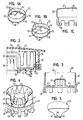
- Fig. 1A 11 shows a perspective view of an airbag holder 10 for fastening an airbag 12 (FIG. Fig. 2 ) on a generator support 14 (FIG. Fig. 2 ) an air bag module which is integrally connected to a diffuser 15.
- the air bag holder 10 consists of an approximately O-shaped retaining ring 16, on the underside of a plurality of latching hooks 18 are formed.
- At The top of the retaining ring 16 is formed along the entire outer circumference, a vertically upwardly extending, closed container wall 20 which is formed thin-walled and flexible.
- a plurality of predetermined breaking points 22 are provided in the form of tear seams, so as not to hinder a lateral deployment of the airbag.
- Fig. 1A is formed by the container wall 20, a circumferentially closed receiving space 24 which is open to the top and bottom of the air bag holder 10 out.
- Fig. 2 shows the airbag holder 10 of Fig. 1A , which is built into an air bag module.
- the airbag mouth of the airbag 12 is provided with a plurality of openings through which the latching hooks 18 of the airbag holder 10 can be inserted.
- the unit thus formed is latched in the generator support 14, whereby the air bag 12 is fixed to the generator support 14.
- the air bag 12 can be folded into the receiving space 24 with the desired folding, without having to take any special safety precautions.
- the subsequently obtained assembly unit can be handled easily and safely, wherein a removable film or the like can be attached to support the folded airbag 12 above the receiving space 24.
- the gas generator 26 can then be inserted from below into the assembly unit thus obtained, wherein it can be latched, for example, in the generator support 14 with the aid of latching hooks 30. Subsequently, a cover 32 of the airbag module can be locked in the generator carrier 14, wherein previously possibly attached to the air bag holder protective film is removed. Subsequently, the airbag module can be fastened via fastening bolts 28, for example, to a contact bridge of a driver's airbag module.
- the Figs. 1B and 1C own another embodiment of an air bag holder 10, which essentially like the airbag holder 10 of Fig. 1A formed, however, is additionally provided on its upper side with a material layer 21 which closes the receiving space 24 upwards.
- the material layer 21 is formed integrally with the flexible wall 20.
- Fig. 1B shows a plurality of predetermined breaking lines 23 in the region of the material layer 21, which permit easy opening of the material layer 21 during deployment of the airbag.
- the airbag can be folded from the underside of the airbag holder in the receiving space 24, wherein subsequently the airbag mouth is guided with openings provided thereon via the latching hooks 18.
- FIG. 3 shows a further embodiment of an air bag holder 40, which basically similar to the airbag holder 10 of Fig. 1A is constructed.
- the air bag holder 40 also has a retaining ring 46 integrally formed on the one hand, a circumferentially closed container wall 42 is, whereby a receiving space 49 is formed.
- latching hooks 48 On the underside of the retaining ring 46 are latching hooks 48, which are for fastening the air bag holder 40 to a component of the air bag module and for clamping the air bag 43 (FIG. Fig. 4, 5 ) serve.
- the air bag holder 40 is provided in the interior of the receiving space 49 with a cage-shaped diffuser 44 which is integrally connected via fastening arms 47 with the retaining ring 46.
- the diffuser 44 forms a cup-shaped receiving space for the gas generator 26 and has for this purpose distributed over its circumference gas passage openings 45.
- Fig. 5 shows in a greatly simplified illustration the air bag 43 of Fig. 4 , It can be seen here that in the area of the airbag mouth the airbag 43 is provided with fastening straps 51, which are spaced apart by a slot 52 which is open towards the outside. In each fastening tab 51, a passage opening 54 is also provided, which serves to perform the latching hook 48.
- each fastening tab 51 can be pulled so far over a latching hook 48 until it can pass through the passage opening 54, so that in the assembled state, a fastening arm 47 is located within each slot 52.
- the airbag 43 After the airbag 43 has been attached to the airbag retainer 40 in the manner described above, the airbag can be folded into the accommodating space 49 formed in the interior of the container wall 42.
- the 6 and 7 show a further embodiment of an air bag holder, which is provided for a passenger airbag module.
- the in the 6 and 7 illustrated airbag holder 60 is rectangular in plan view and in turn has a retaining ring 62 which is provided on its underside with latching hooks 68.
- a circumferentially closed, vertically extending container wall 64 is provided, which forms a receiving space 66 for an airbag 78.
- a longitudinally and vertically extending partition wall 70 is provided, which is connected via webs 72 with the retaining ring 62.
- the airbag 78 is fastened with its airbag mouth to the airbag holder 60 in that the latching hooks 68 are inserted through openings in the airbag mouth, so that only one peripheral edge 79 of the airbag 78 remains outside of the airbag holder 60.
- the airbag 78 is completely housed within the receiving space 66.
- the mounting unit consisting of air bag holder 60 and air bag 78 is used for installation in a mounting recess 80 which is provided in the area of a dashboard 82.
- a gas passage 83 is provided to convey gas of a gas generator 84 into the interior of the air bag 78.
- the gas generator 84 is mounted sealed in the region of the gas channel 83.
- the rear end of the cylindrical gas generator 84 over attached a clamp attachment 86 to a cross member 88 of the associated vehicle by means of a slot 89 height adjustable.
- the mounting unit consisting of airbag holder 60 and airbag 78 can be inserted into the mounting recess 80, whereupon the latching hooks 68 engage in the region of the corresponding openings in the bottom of the mounting recess 80.
- the essential part of the airbag module is already mounted in the dashboard 82, but without the gas generator 84 is already installed.
- further assembly work such as the attachment of a cover can be made. Only when this work is completed, the gas generator 84 must be mounted by sealingly mounted in the region of the gas channel 83 and secured by the clamp attachment 86.
- the slot 89 is provided according to the invention, which allows a certain balance between the provided in the dashboard 82 airbag module and the body-mounted cross member 88.
Landscapes
- Engineering & Computer Science (AREA)
- Mechanical Engineering (AREA)
- Air Bags (AREA)
Description
- Die vorliegende Erfindung betrifft einen Luftsackhalter zum Befestigen eines Luftsacks an einem Bauteil eines Luftsackmoduls nach dem Oberbegriff des Anspruchs 1 (vgl.
US 5,636,859 ). - Derartige Luftsackhalter dienen zur Befestigung eines Luftsacks an einer Grundplatte oder an einem Generatorträger eines Luftsackmoduls.
- Aus der
US 5,498,030 ist ein Luftsackmodul bekannt, bei dem aus dem Gewebe des Luftsacks ein Beutel genäht ist, der als Gehäuse und Abdeckung des Luftsackmoduls dient. - Es ist die Aufgabe der Erfindung, einen Luftsackhalter zu schaffen, der eine sichere und kostengünstige Montage eines Luftsackmoduls ermöglicht.
- Die Lösung dieser Aufgabe erfolgt durch die Merkmale des Anspruchs 1 und insbesondere durch einen Luftsackhalter der eingangs genannten Art, der an seiner Unterseite mehrere Verbindungselemente aufweist, die zur Befestigung des Luftsackhalters an dem Bauteil des Luftsackmoduls dienen, wobei ferner an der Oberseite des Luftsackhalters eine sich entlang des Umfangs des Halters erstreckende Behälterwand vorgesehen ist, die in ihrem Inneren einen Aufnahmeraum für den Luftsack bildet.
- Der erfindungsgemäße Luftsackhalter ermöglicht das Falten eines Luftsacks in den Aufnahmeraum hinein, wobei der in den Aufnahmeraum gefaltete Luftsack an seinem Außenumfang durch die Behälterwand gehalten ist. Hierdurch ist ausgeschlossen, dass sich Luftsackgewebe während der Montage einer Abdeckung des Luftsackmoduls zwischen der Abdeckung und dem Luftsackmodul einklemmt bzw. dass sich die vorgesehene Lüftsackfaltung unerwünscht auflöst.
- Mit dem erfindungsgemäßen Luftsackhalter kann der Luftsack mit seinem Luftsackmund zunächst durch den Luftsackhalter gezogen und anschließend an den Verbindungselementen befestigt werden. Anschließend wird der Luftsackhalter an dem Bauteil des Luftsackmoduls, beispielsweise einem Generatorträger oder einer Basisplatte, mittels der Verbindungselemente befestigt, wodurch der Luftsack an dem Bauteil gehalten ist. Anschließend kann der Luftsack in den durch die Behälterwand gebildeten Aufnahmeraum hineingefaltet werden, wodurch eine kompakte Montageeinheit gebildet ist, die noch nicht mit einem Gasgenerator gekoppelt ist, der nur unter erhöhten Sicherheitsbedingungen gehandhabt werden darf. Diese gebildete Montageeinheit stellt ein autarkes Bauteil dar, mit dem sämtliche für die Luftsackentfaltung wichtige Funktionen wie beispielsweise Faltungssteuerung, Steuerung des Gasstroms sowie Fixierung des Package, eingestellt werden können.
- Vorteilhafte Ausführungsformen der Erfindung sind in der Beschreibung, der Zeichnung sowie den Unteransprüchen beschrieben.
- Nach einer ersten vorteilhaften Ausführungsform kann die Behälterwand dünnwandig und insbesondere flexibel ausgebildet sein. Hierdurch wird eine laterale Entfaltung des Luftsacks unterstützt, die bei bestimmten Anwendungsfällen wünschenswert ist.
- Nach einer weiteren Ausbildung der Erfindung können in der Behälterwand Sollbruchstellen, beispielsweise Reißnähte oder Perforierungen vorgesehen sein, um ein seitliches Entfalten des Luftsacks zu unterstützen bzw. nicht zu behindern.
- Nach einer weiteren vorteilhaften Ausführungsform kann innerhalb des Aufnahmeraums zumindest eine Trennwand vorgesehen sein. Eine solche Trennwand kann dazu dienen, die Luftsackentfaltung durch eine vorbestimmte Dichteverteilung des Luftsackgewebes innerhalb des Aufnahmeraumes zu steuern. Auch kann durch die Trennwand eine Steuerung der Gasstromrichtung erzielt werden, d.h. die Trennwand kann als Gasverteiler dienen.
- Nach einer weiteren vorteilhaften Ausführungsform ist der Aufnahmeraum an seiner Oberseite verschlossen, beispielsweise durch eine Membran oder Folie. Die Membran oder Folie kann entweder nur zu Transportzwecken dienen und von dem Luftsackhalter wieder entfernbar bzw. abziehbar sein. Nach einer weiteren vorteilhaften Ausführungsform ist jedoch die Oberseite des Aufnahmeraumes durch eine Folie oder dünne Materialschicht verschlossen, die einstückig mit der Wand ausgebildet ist. Hierdurch ergibt sich der Vorteil, dass der gefaltete Luftsack innerhalb des Aufnahmeraums gehalten ist und sogar von der Unterseite des Luftsackhalters in den Aufnahmeraum hineingefaltet werden kann. Im gefalteten Zustand besteht somit nicht die Gefahr, dass sich Luftsackgewebe aus dem Aufnahmeraum nach oben herausbewegt. Die Membran, Folie oder dünne Materialschicht kann auch mit einer oder mehreren Sollbruchstellen bzw. Sollbruchnähten versehen sein, um beim Entfalten des Luftsacks ein störungsfreies Öffnen zu ermöglichen.
- Nach einer weiteren vorteilhaften Ausführungsform ist in den Halter ein insbesondere käfigförmiger Diffusor integriert. Bei dieser Ausführungsform ist innerhalb des Aufnahmeraums durch den Diffusor Platz freigehalten, in den zu einem späteren Montagezeitpunkt ein Gasgenerator eingesetzt werden kann.
- Nach einer weiteren Ausbildung der Erfindung kann der Halter an seiner Unterseite Öffnungen für den Durchtritt von Befestigungslaschen des Luftsacks aufweisen. Auf diese Weise ist es möglich, den Luftsackmund an dem Halter zu befestigen und gleichzeitig im Bereich des Aufnahmeraums einen käfigförmigen Diffusor anzuordnen.
- Wie eingangs bereits beschrieben, weist eine Montageeinheit gemäß der Erfindung einen erfindungsgemäßen Luftsackhalter auf, wobei in dem Aufnahmeraum des Luftsackhalters ein zusammengefalteter Luftsack angeordnet ist. Eine derartige Montageeinheit ermöglicht nicht nur ein sicheres Montieren des Luftsacks an dem Luftsackmodul, derart dass ein unerwünschtes Einklemmen von Luftsackgewebe vermieden ist. Erfindungsgemäß ermöglicht die Montageeinheit darüber hinaus eine selbständige und aufgrund des fehlenden Gasgenerators auch sicher zu handhabende Baueinheit, in die hinein das Luftsackgewebe gefaltet werden kann, so dass ein kompaktes Package erhalten wird.
- Nach einer weiteren Ausführungsform der Erfindung kann der in die Montageeinheit eingefaltete Luftsack durch eine entfernbare Abdeckung in dem Aufnahmeraum gehalten sein. Hierbei kann es sich beispielsweise um eine entfernbare Folie oder einen Klebestreifen handeln, die erst dann entfernt werden, wenn die Montageeinheit an dem Luftsackmodul befestigt ist und die Abdeckung des Luftsackmoduls montiert werden soll.
- Nachfolgend wird die vorliegende Erfindung beispielhaft anhand vorteilhafter Ausführungsformen und unter Bezugnahme auf die beigefügten Zeichnungen beschrieben. Es zeigen:
- Fig. 1A
- eine perspektivische Ansicht einer ersten Ausführungsform eines Luftsackhalters;
- Fig. 1B
- eine perspektivische Ansicht einer weiteren Ausführungsform eines Luftsackhalters;
- Fig. 1 C
- eine vergrößerte Teilquerschnittsansicht des Luftsackhalters von
Fig. 1 B; - Fig. 2
- einen Schnitt durch ein Luftsackmodul mit einem Luftsackhalter nach
Fig. 1A ; - Fig. 3
- einen Schnitt durch eine weitere Ausführungsform eines Luftsackhalters;
- Fig. 4
- eine perspektivische Ansicht des Luftsackhalters von
Fig. 3 mit eingefaltetem Luftsack; - Fig. 5
- eine schematische, verkleinerte Ansicht des Luftsacks von
Fig. 4 ; - Fig. 6
- eine perspektivische Darstellung eines weiteren Luftsackhalters gemäß der Erfindung zum Einbau in eine Armaturentafel; und
- Fig. 7
- eine Schnittansicht durch den Luftsackhalter von
Fig. 6 . -
Fig. 1A zeigt eine perspektivische Ansicht eines Luftsackhalters 10 zum Befestigen eines Luftsacks 12 (Fig. 2 ) an einem Generatorträger 14 (Fig. 2 ) eines Luftsackmoduls, der einstückig mit einem Diffusor 15 verbunden ist. Der Luftsackhalter 10 besteht aus einem annähernd O-förmigen Haltering 16, an dessen Unterseite mehrere Rasthaken 18 angeformt sind. An der Oberseite des Halterings 16 ist entlang des gesamten Außenumfangs eine sich vertikal nach oben erstreckende, geschlossene Behälterwand 20 angeformt, die dünnwandig und flexibel ausgebildet ist. Senkrecht zur Umfangsrichtung sind an der Behälterwand mehrere Sollbruchstellen 22 in Form von Reißnähten vorgesehen, um ein seitliches Entfalten des Luftsackes nicht zu behindern. - Wie
Fig. 1A zeigt, ist durch die Behälterwand 20 ein in Umfangsrichtung geschlossener Aufnahmeraum 24 gebildet, der zur Oberseite und zur Unterseite des Luftsackhalters 10 hin offen ist. -
Fig. 2 zeigt den Luftsackhalter 10 vonFig. 1A , der in ein Luftsackmodul eingebaut ist. Wie zu erkennen ist, ist der Luftsackmund des Luftsacks 12 mit mehreren Öffnungen versehen, durch welche die Rasthaken 18 des Luftsackhalters 10 gesteckt werden können. Hierzu wird zunächst der Luftsackmund von oben durch den Luftsackhalter 10 gesteckt und anschließend werden die Rasthaken 18 durch die am Luftsackmund vorgesehenen Öffnungen geführt. Anschließend wird die so gebildete Einheit in dem Generatorträger 14 verrastet, wodurch der Luftsack 12 an dem Generatorträger 14 befestigt ist. - Da zu diesem Zeitpunkt ein Gasgenerator 26 des Luftsackmoduls noch nicht montiert ist, kann der Luftsack 12 mit der gewünschten Faltung in den Aufnahmeraum 24 hineingefaltet werden, ohne dass besondere Sicherheitsvorkehrungen getroffen werden müssten. Die anschließend erhaltene Montageeinheit kann einfach und gefahrlos gehandhabt werden, wobei zur Halterung des gefalteten Luftsacks 12 oberhalb des Aufnahmeraums 24 eine entfernbare Folie oder dergleichen angebracht werden kann.
- In die so erhaltene Montageeinheit kann anschließend von unten der Gasgenerator 26 eingesetzt werden, wobei dieser beispielsweise in dem Generatorträger 14 mit Hilfe von Rasthaken 30 verrastet werden kann. Anschließend kann eine Abdeckung 32 des Luftsackmoduls in dem Generatorträger 14 verrastet werden, wobei vorher gegebenenfalls die an dem Luftsackhalter angebrachte Schutzfolie entfernt wird. Anschließend kann das Luftsackmodul über Befestigungsbolzen 28 beispielsweise an einer Kontaktbrücke eines Fahrerairbagmoduls befestigt werden.
- Die
Fig. 1B und 1C eigen eine weitere Ausführungsform eines Luftsackhalters 10, der im Wesentlichen wie der Luftsackhalter 10 vonFig. 1A ausgebildet, jedoch zusätzlich an seiner Oberseite mit einer Materialschicht 21 versehen ist, die den Aufnahmeraum 24 nach oben hin verschließt. Wie insbesondereFig. 1C zeigt, ist die Materialschicht 21 einstückig mit der flexiblen Wand 20 ausgebildet. - Ferner zeigt
Fig. 1B , dass im Bereich der Materialschicht 21 mehrere Sollbruchlinien 23 vorgesehen sind, die ein leichtes Öffnen der Materialschicht 21 beim Entfalten des Luftsacks ermöglichen. - Bei der in den
Fig. 1B und 1C gezeigten Ausführungsformen des Luftsackhalters kann der Luftsack von der Unterseite des Luftsackhalters in den Aufnahmeraum 24 hineingefaltet werden, wobei anschließend der Luftsackmund mit daran vorgesehenen Öffnungen über die Rasthaken 18 geführt wird. -
Fig. 3 zeigt eine weitere Ausführungsform eines Luftsackhalters 40, der grundsätzlich ähnlich wie der Luftsackhalter 10 vonFig. 1A aufgebaut ist. Der Luftsackhalter 40 weist ebenfalls einen Haltering 46 auf, an den einstückig eine in Umfangsrichtung geschlossene Behälterwand 42 angeformt ist, wodurch ein Aufnahmeraum 49 gebildet ist. An der Unterseite des Halterings 46 befinden sich Rasthaken 48, die zur Befestigung des Luftsackhalters 40 an ein Bauteil des Luftsackmoduls sowie zur Klemmung des Luftsacks 43 (Fig. 4, 5 ) dienen. - Wie die
Fig. 3 und 4 zeigen, ist der Luftsackhalter 40 im Inneren des Aufnahmeraums 49 mit einem käfigförmigen Diffusor 44 versehen, der über Befestigungsarme 47 einstückig mit dem Haltering 46 verbunden ist. Der Diffusor 44 bildet einen topfförmigen Aufnahmeraum für den Gasgenerator 26 und weist hierzu über seinen Umfang verteilt Gasdurchtrittsöffnungen 45 auf. -
Fig. 5 zeigt in stark vereinfachter Darstellung den Luftsack 43 vonFig. 4 . Hierbei ist zu erkennen, dass im Bereich des Luftsackmundes der Luftsack 43 mit Befestigungslaschen 51 versehen ist, die durch einen nach außen offenen Schlitz 52 beabstandet sind. In jeder Befestigungslasche 51 ist ferner eine Durchtrittsöffnung 54 vorgesehen, die zum Durchführen der Rasthaken 48 dient. - Durch gemeinsame Betrachtung der
Fig. 4 und 5 ist zu erkennen, dass der Luftsack 43 mit den Befestigungslaschen 51 durch Öffnungen 41 geführt wird, die von den Befestigungsarmen 47 und dem Diffusor 44 sowie dem Haltering 46 begrenzt sind. Durch den zwischen den Befestigungslaschen 51 vorgesehen Schlitz 52 kann jede Befestigungslasche 51 so weit über einen Rasthaken 48 gezogen werden, bis dieser durch die Durchtrittsöffnung 54 gelangen kann, so dass im montierten Zustand sich innerhalb jedes Schlitzes 52 ein Befestigungsarm 47 befindet. - Nachdem der Luftsack 43 auf die oben beschriebene Weise an dem Luftsackhalter 40 befestigt worden ist, kann der Luftsack in den im Inneren der Behälterwand 42 gebildeten Aufnahmeraum 49 hineingefaltet werden.
- Die
Fig. 6 und 7 zeigen eine weitere Ausführungsform eines Luftsackhalters, der für ein Beifahrerairbagmodul vorgesehen ist. Der in denFig. 6 und 7 dargestellte Luftsackhalter 60 ist in Draufsicht rechteckig ausgebildet und weist wiederum einen Haltering 62 auf, der an seiner Unterseite mit Rasthaken 68 versehen ist. An der Oberseite des Halterings 62 ist eine in Umfangrichtung geschlossene, sich vertikal erstreckende Behälterwand 64 vorgesehen, die einen Aufnahmeraum 66 für einen Luftsack 78 bildet. Im Inneren des Aufnahmeraums 66 ist eine sich in Längsrichtung und vertikal erstreckende Trennwand 70 vorgesehen, die über Stege 72 mit dem Haltering 62 verbunden ist. - Wie die
Fig. 6 und 7 zeigen, ist der Luftsack 78 mit seinem Luftsackmund an dem Luftsackhalter 60 befestigt, indem die Rasthaken 68 durch Öffnungen im Luftsackmund gesteckt sind, so dass nur ein Umfangsrand 79 des Luftsacks 78 außerhalb des Luftsackhalters 60 verbleibt. Im Übrigen ist der Luftsack 78 vollständig innerhalb des Aufnahmeraums 66 untergebracht. - Wie
Fig. 6 zeigt, dient die Montageeinheit bestehend aus Luftsackhalter 60 und Luftsack 78 zum Einbau in eine Montageaussparung 80, die im Bereich einer Armaturentafel 82 vorgesehen ist. Am Boden der Montageaussparung 80 ist ein Gaskanal 83 vorgesehen, um Gas eines Gasgenerators 84 in das Innere des Luftsacks 78 zu fördern. Zu diesem Zweck ist der Gasgenerator 84 im Bereich des Gaskanals 83 abgedichtet montiert. Das hintere Ende des zylinderförmigen Gasgenerators 84 ist dagegen über eine Klemmbefestigung 86 an einem Querträger 88 des zugehörigen Fahrzeugs mit Hilfe eines Langlochs 89 höhenverstellbar befestigt. - Bei dieser Ausführungsform ergibt sich der außerordentliche Vorteil, dass die Montageeinheit bestehend aus Luftsackhalter 60 und Luftsack 78 in die Montageaussparung 80 eingesetzt werden kann, woraufhin die Rasthaken 68 im Bereich der dazu korrespondierenden Öffnungen im Boden der Montageaussparung 80 verrasten. Hierdurch ist der wesentliche Teil des Luftsackmoduls bereits in der Armaturentafel 82 montiert, ohne dass jedoch der Gasgenerator 84 bereits eingebaut ist. Somit können weitere Montagearbeiten, wie beispielsweise das Anbringen einer Abdeckung vorgenommen werden. Erst wenn diese Arbeiten abgeschlossen sind, muss der Gasgenerator 84 montiert werden, indem dieser im Bereich des Gaskanals 83 abgedichtet montiert und durch die Klemmbefestigung 86 befestigt wird.
- Da es in der Praxis häufig zu geringen Toleranzen zwischen dem fahrzeugfesten Querträger 88 und der Armaturentafel 82 kommt, ist erfindungsgemäß das Langloch 89 vorgesehen, das einen gewissen Ausgleich zwischen dem im Bereich der Armaturentafel 82 vorgesehenen Airbagmodul und dem karosseriefesten Querträger 88 ermöglicht.
-
- 10
- Luftsackhalter
- 12
- Luftsack
- 14
- Generatorträger
- 15
- Diffusor
- 16
- Haltering
- 18
- Rasthaken
- 20
- Behälterwand
- 21
- dünne Materialschicht
- 22
- Sollbruchstellen
- 23
- Sollbruchlinien
- 24
- Aufnahmeraum
- 26
- Gasgenerator
- 28
- Befestigungsbolzen
- 30
- Rasthaken
- 32
- Abdeckung
- 40
- Luftsackhalter
- 41
- Öffnungen
- 42
- Behälterwand
- 43
- Luftsack
- 44
- Diffusor
- 45
- Gasdurchtrittsöffnungen
- 46
- Haltering
- 47
- Befestigungsarme
- 48
- Rasthaken
- 49
- Aufnahmeraum
- 51
- Befestigungslaschen
- 52
- Schlitz
- 54
- Durchtrittsöffnung
- 60
- Luftsackhalter
- 62
- Haltering
- 64
- Behälterwand
- 66
- Aufnahmeraum
- 68
- Rasthaken
- 70
- Trennwand
- 72
- Stege
- 78
- Luftsack
- 79
- Luftsackrand
- 80
- Montageaussparung
- 82
- Armaturentafel
- 83
- Gaskanal
- 84
- Gasgenerator
- 86
- Klemmbefestigung
- 88
- Querträger
- 89
- Langloch
Claims (11)
- Luftsackhalter (10, 40, 60) zum Befestigen eines Luftsacks (12, 43, 78) an einem Bauteil (14, 82) eines Luftsackmoduls, wobei der Halter (10, 40, 60) einen Haltering (16, 46, 62) aufweist,
dadurch gekennzeichnet, dass
an der Unterseite des Halters (10, 40, 60) mehrere Verbindungselemente (18, 48, 68) vorgesehen sind, die zum Befestigen des Halters (10, 40, 60) an dem Bauteil dienen, und
dass an der Oberseite des Halters (10, 40, 60) eine sich entlang des Umfangs des Halters erstreckende Behälterwand (20, 42, 64) vorgesehen ist, die in ihrem Inneren einen Aufnahmeraum (24, 49, 66) für den Luftsack (12, 43, 78) bildet. - Luftsackhalter nach Anspruch 1,
dadurch gekennzeichnet, dass
die Behälterwand (20, 42, 64) dünnwandig und insbesondere flexibel ausgebildet ist. - Luftsackhalter nach einem der vorstehenden Ansprüche,
dadurch gekennzeichnet, dass
in der Behälterwand (20) Sollbruchstellen (22), insbesondere Reißnähte und/oder Perforierungen vorgesehen sind. - Luftsackhalter nach einem der vorstehenden Ansprüche,
dadurch gekennzeichnet, dass
innerhalb des Aufnahmeraumes (66) zumindest eine Trennwand (70) vorgesehen ist. - Luftsackhalter nach einem der vorstehenden Ansprüche,
dadurch gekennzeichnet, dass
der Aufnahmeraum (24, 49, 66) an seiner Oberseite vollständig offen ist. - Luftsackhalter nach einem der vorstehenden Ansprüche 1 bis 4,
dadurch gekennzeichnet, dass
der Aufnahmeraum (24, 49, 66) an seiner Oberseite durch eine Membran, Folie oder dünne Materialschicht (21) verschlossen ist,
die insbesondere einstückig mit der Wand ausgebildet und/oder mit Sollbruchstellen (23) versehen ist. - Luftsackhalter nach einem der vorstehenden Ansprüche,
dadurch gekennzeichnet, dass
in den Halter (40) ein insbesondere käfigförmiger Diffusor (44) integriert ist. - Luftsackhalter nach Anspruch 7,
dadurch gekennzeichnet, dass
durch den Diffusor (44) und die Behälterwand (42) zumindest bereichsweise ein ringförmiger Aufnahmeraum (49) gebildet ist. - Luftsackhalter nach einem der vorstehenden Ansprüche,
dadurch gekennzeichnet, dass
der Halter (40) an seiner Unterseite Öffnungen (41) für den Durchtritt von Befestigungslaschen (S1) des Luftsacks (43) aufweist. - Montageeinheit mit einem Luftsackhalter (10, 40, 60) nach zumindest einem der vorstehenden Ansprüche, wobei in dem Aufnahmeraum (24, 49, 66) ein zusammengefalteter Luftsack (12, 43, 78) angeordnet ist.
- Montageeinheit nach Anspruch 10,
dadurch gekennzeichnet, dass
der gefaltete Luftsack (12, 43, 78) durch eine an der Oberseite des Luftsackhalters vorgesehene, entfernbare Abdeckung oder durch eine mit dem Luftsackhalter insbesondere einstückig verbundene Membran oder Materialschicht (21) in dem Aufnahmeraum (24, 49, 66) gehalten ist.
Priority Applications (3)
| Application Number | Priority Date | Filing Date | Title |
|---|---|---|---|
| DE50311476T DE50311476D1 (de) | 2003-05-26 | 2003-05-26 | Luftsackhalter |
| AT03011864T ATE430068T1 (de) | 2003-05-26 | 2003-05-26 | Luftsackhalter |
| EP03011864A EP1481855B1 (de) | 2003-05-26 | 2003-05-26 | Luftsackhalter |
Applications Claiming Priority (1)
| Application Number | Priority Date | Filing Date | Title |
|---|---|---|---|
| EP03011864A EP1481855B1 (de) | 2003-05-26 | 2003-05-26 | Luftsackhalter |
Publications (2)
| Publication Number | Publication Date |
|---|---|
| EP1481855A1 EP1481855A1 (de) | 2004-12-01 |
| EP1481855B1 true EP1481855B1 (de) | 2009-04-29 |
Family
ID=33104077
Family Applications (1)
| Application Number | Title | Priority Date | Filing Date |
|---|---|---|---|
| EP03011864A Expired - Lifetime EP1481855B1 (de) | 2003-05-26 | 2003-05-26 | Luftsackhalter |
Country Status (3)
| Country | Link |
|---|---|
| EP (1) | EP1481855B1 (de) |
| AT (1) | ATE430068T1 (de) |
| DE (1) | DE50311476D1 (de) |
Families Citing this family (5)
| Publication number | Priority date | Publication date | Assignee | Title |
|---|---|---|---|---|
| DE102005060892A1 (de) * | 2005-12-20 | 2007-06-28 | GM Global Technology Operations, Inc., Detroit | Airbagmodul mit mindestens einem Befestigungselement |
| DE102006041145B4 (de) * | 2006-09-01 | 2008-08-14 | Autoliv Development Ab | Gassack-Einheit |
| EP2236361B1 (de) * | 2009-03-31 | 2016-07-20 | Autoliv Development AB | Luftsackbaugruppe |
| DE102009017920A1 (de) | 2009-04-16 | 2010-10-28 | Takata-Petri Ag | Gassackanordnung für ein Fahrzeuginsassen-Rückhaltesystem und Verfahren zum Herstellen einer Gassackanordnung |
| DE102009017919A1 (de) | 2009-04-16 | 2010-10-21 | Takata-Petri Ag | Gassackanordnung für ein Fahrzeuginsassen-Rückhaltesystem und Verfahren zum Herstellen einer Gassackanordnung |
Family Cites Families (8)
| Publication number | Priority date | Publication date | Assignee | Title |
|---|---|---|---|---|
| EP0732237A1 (de) * | 1995-03-16 | 1996-09-18 | General Motors Corporation | Lenkradvorrichtung |
| US5498030A (en) * | 1995-03-28 | 1996-03-12 | General Motors Corporation | Air bag module |
| US5568936A (en) * | 1995-11-08 | 1996-10-29 | Morton International, Inc. | Airbag module case for side impact airbag module |
| US5636859A (en) * | 1995-11-09 | 1997-06-10 | General Motors Corporation | Air bag module assembly |
| US5873598A (en) * | 1996-08-27 | 1999-02-23 | Toyo Tire & Rubber Co., Ltd. | Air bag device |
| JP4635293B2 (ja) * | 2000-04-07 | 2011-02-23 | タカタ株式会社 | エアバッグ装置 |
| DE10136893B4 (de) * | 2001-07-25 | 2006-02-09 | Takata-Petri Ag | Airbagmodul |
| DE10152624A1 (de) * | 2001-10-25 | 2003-05-15 | Breed Automotive Tech | Hupentechnik für ein Airbagmodul |
-
2003
- 2003-05-26 DE DE50311476T patent/DE50311476D1/de not_active Expired - Lifetime
- 2003-05-26 AT AT03011864T patent/ATE430068T1/de not_active IP Right Cessation
- 2003-05-26 EP EP03011864A patent/EP1481855B1/de not_active Expired - Lifetime
Also Published As
| Publication number | Publication date |
|---|---|
| EP1481855A1 (de) | 2004-12-01 |
| DE50311476D1 (de) | 2009-06-10 |
| ATE430068T1 (de) | 2009-05-15 |
Similar Documents
| Publication | Publication Date | Title |
|---|---|---|
| DE69926866T2 (de) | Saülemontierter seitenairbag | |
| DE10224726B4 (de) | Airbag-Halteklammer | |
| DE69001177T2 (de) | Luftsackeinbau. | |
| EP3697648B1 (de) | Fahrzeuginsassen-rückhaltesystem mit einem gassackmodul und verfahren zum zusammenlegen eines gassacks | |
| DE69616753T2 (de) | Seitenaufpral-airbagmodul in weicher umhüllung | |
| DE102006044850B4 (de) | Säulenrampenstruktur zur Verhinderung einer Störung bei der Entfaltung eines Vorhangairbags | |
| DE10342306B4 (de) | Gassackvorrichtung für den Knieschutz | |
| DE69812201T2 (de) | Airbagvorrichtung für Beifahrersitz | |
| EP3697649B1 (de) | Fahrzeuginsassen-rückhaltesystem mit einem gassackmodul | |
| DE20022020U1 (de) | Gassackmodul | |
| DE10065795A1 (de) | Haltevorrichtung | |
| EP1087879A1 (de) | Rückhalteeinrichtung für ein eine airbaganordnung abdeckendes verkleidungsteil | |
| DE102010040119A1 (de) | Gassack für ein Personen-Schutzsystem eines Fahrzeugs und Verfahren zu dessen Herstellung | |
| DE10303714A1 (de) | Vorrichtug zum Schützen von Fahrzeuginsassen | |
| EP1201510A1 (de) | Sicherheitsvorrichtung für Kraftfahrzeuge | |
| DE69916229T2 (de) | Luftsack | |
| WO2021083873A1 (de) | Gassackanordnung für ein fahrzeuginsassen-rückhaltesystem und verfahren zum schützen eines fahrzeuginsassen | |
| EP1481855A1 (de) | Luftsackhalter | |
| DE102004014742A1 (de) | Fahrzeug mit Vorhang-Airbag | |
| EP3883820B1 (de) | Gassackmodul für ein kraftfahrzeug | |
| DE19710063B4 (de) | Airbag mit Gaserzeuger | |
| EP1034988B1 (de) | Anbindung für die Instrumententafel eines mit einem Airbag ausgerüsteten Personenkraftwagens | |
| EP3535166B1 (de) | Gassack für ein kraftfahrzeug sowie verfahren zur herstellung eines solchen gassacks | |
| EP1022196B1 (de) | Gassack-Rückhaltemodul | |
| DE102009042308A1 (de) | Rückhalteeinrichtung für Insassen eines Fahrzeugs mit einem Airbagsystem |
Legal Events
| Date | Code | Title | Description |
|---|---|---|---|
| PUAI | Public reference made under article 153(3) epc to a published international application that has entered the european phase |
Free format text: ORIGINAL CODE: 0009012 |
|
| AK | Designated contracting states |
Kind code of ref document: A1 Designated state(s): AT BE BG CH CY CZ DE DK EE ES FI FR GB GR HU IE IT LI LU MC NL PT RO SE SI SK TR |
|
| AX | Request for extension of the european patent |
Extension state: AL LT LV MK |
|
| 17P | Request for examination filed |
Effective date: 20040505 |
|
| AKX | Designation fees paid |
Designated state(s): AT BE BG CH CY CZ DE DK EE ES FI FR GB GR HU IE IT LI LU MC NL PT RO SE SI SK TR |
|
| GRAP | Despatch of communication of intention to grant a patent |
Free format text: ORIGINAL CODE: EPIDOSNIGR1 |
|
| GRAS | Grant fee paid |
Free format text: ORIGINAL CODE: EPIDOSNIGR3 |
|
| GRAA | (expected) grant |
Free format text: ORIGINAL CODE: 0009210 |
|
| AK | Designated contracting states |
Kind code of ref document: B1 Designated state(s): AT BE BG CH CY CZ DE DK EE ES FI FR GB GR HU IE IT LI LU MC NL PT RO SE SI SK TR |
|
| REG | Reference to a national code |
Ref country code: GB Ref legal event code: FG4D Free format text: NOT ENGLISH |
|
| REG | Reference to a national code |
Ref country code: CH Ref legal event code: EP |
|
| REF | Corresponds to: |
Ref document number: 50311476 Country of ref document: DE Date of ref document: 20090610 Kind code of ref document: P |
|
| REG | Reference to a national code |
Ref country code: IE Ref legal event code: FG4D |
|
| NLV1 | Nl: lapsed or annulled due to failure to fulfill the requirements of art. 29p and 29m of the patents act | ||
| PG25 | Lapsed in a contracting state [announced via postgrant information from national office to epo] |
Ref country code: ES Free format text: LAPSE BECAUSE OF FAILURE TO SUBMIT A TRANSLATION OF THE DESCRIPTION OR TO PAY THE FEE WITHIN THE PRESCRIBED TIME-LIMIT Effective date: 20090809 Ref country code: FI Free format text: LAPSE BECAUSE OF FAILURE TO SUBMIT A TRANSLATION OF THE DESCRIPTION OR TO PAY THE FEE WITHIN THE PRESCRIBED TIME-LIMIT Effective date: 20090429 Ref country code: PT Free format text: LAPSE BECAUSE OF FAILURE TO SUBMIT A TRANSLATION OF THE DESCRIPTION OR TO PAY THE FEE WITHIN THE PRESCRIBED TIME-LIMIT Effective date: 20090829 |
|
| BERE | Be: lapsed |
Owner name: DELPHI TECHNOLOGIES, INC. Effective date: 20090531 |
|
| PG25 | Lapsed in a contracting state [announced via postgrant information from national office to epo] |
Ref country code: SE Free format text: LAPSE BECAUSE OF FAILURE TO SUBMIT A TRANSLATION OF THE DESCRIPTION OR TO PAY THE FEE WITHIN THE PRESCRIBED TIME-LIMIT Effective date: 20090729 Ref country code: SI Free format text: LAPSE BECAUSE OF FAILURE TO SUBMIT A TRANSLATION OF THE DESCRIPTION OR TO PAY THE FEE WITHIN THE PRESCRIBED TIME-LIMIT Effective date: 20090429 Ref country code: NL Free format text: LAPSE BECAUSE OF FAILURE TO SUBMIT A TRANSLATION OF THE DESCRIPTION OR TO PAY THE FEE WITHIN THE PRESCRIBED TIME-LIMIT Effective date: 20090429 |
|
| REG | Reference to a national code |
Ref country code: IE Ref legal event code: FD4D |
|
| PG25 | Lapsed in a contracting state [announced via postgrant information from national office to epo] |
Ref country code: MC Free format text: LAPSE BECAUSE OF NON-PAYMENT OF DUE FEES Effective date: 20090531 |
|
| REG | Reference to a national code |
Ref country code: CH Ref legal event code: PL |
|
| PG25 | Lapsed in a contracting state [announced via postgrant information from national office to epo] |
Ref country code: IE Free format text: LAPSE BECAUSE OF FAILURE TO SUBMIT A TRANSLATION OF THE DESCRIPTION OR TO PAY THE FEE WITHIN THE PRESCRIBED TIME-LIMIT Effective date: 20090429 Ref country code: CZ Free format text: LAPSE BECAUSE OF FAILURE TO SUBMIT A TRANSLATION OF THE DESCRIPTION OR TO PAY THE FEE WITHIN THE PRESCRIBED TIME-LIMIT Effective date: 20090429 Ref country code: EE Free format text: LAPSE BECAUSE OF FAILURE TO SUBMIT A TRANSLATION OF THE DESCRIPTION OR TO PAY THE FEE WITHIN THE PRESCRIBED TIME-LIMIT Effective date: 20090429 Ref country code: CH Free format text: LAPSE BECAUSE OF NON-PAYMENT OF DUE FEES Effective date: 20090531 Ref country code: DK Free format text: LAPSE BECAUSE OF FAILURE TO SUBMIT A TRANSLATION OF THE DESCRIPTION OR TO PAY THE FEE WITHIN THE PRESCRIBED TIME-LIMIT Effective date: 20090429 Ref country code: RO Free format text: LAPSE BECAUSE OF FAILURE TO SUBMIT A TRANSLATION OF THE DESCRIPTION OR TO PAY THE FEE WITHIN THE PRESCRIBED TIME-LIMIT Effective date: 20090429 Ref country code: LI Free format text: LAPSE BECAUSE OF NON-PAYMENT OF DUE FEES Effective date: 20090531 |
|
| PG25 | Lapsed in a contracting state [announced via postgrant information from national office to epo] |
Ref country code: SK Free format text: LAPSE BECAUSE OF FAILURE TO SUBMIT A TRANSLATION OF THE DESCRIPTION OR TO PAY THE FEE WITHIN THE PRESCRIBED TIME-LIMIT Effective date: 20090429 |
|
| PLBE | No opposition filed within time limit |
Free format text: ORIGINAL CODE: 0009261 |
|
| STAA | Information on the status of an ep patent application or granted ep patent |
Free format text: STATUS: NO OPPOSITION FILED WITHIN TIME LIMIT |
|
| GBPC | Gb: european patent ceased through non-payment of renewal fee |
Effective date: 20090729 |
|
| PG25 | Lapsed in a contracting state [announced via postgrant information from national office to epo] |
Ref country code: BG Free format text: LAPSE BECAUSE OF FAILURE TO SUBMIT A TRANSLATION OF THE DESCRIPTION OR TO PAY THE FEE WITHIN THE PRESCRIBED TIME-LIMIT Effective date: 20090729 |
|
| 26N | No opposition filed |
Effective date: 20100201 |
|
| PG25 | Lapsed in a contracting state [announced via postgrant information from national office to epo] |
Ref country code: GB Free format text: LAPSE BECAUSE OF NON-PAYMENT OF DUE FEES Effective date: 20090729 |
|
| PG25 | Lapsed in a contracting state [announced via postgrant information from national office to epo] |
Ref country code: BE Free format text: LAPSE BECAUSE OF NON-PAYMENT OF DUE FEES Effective date: 20090531 |
|
| PGFP | Annual fee paid to national office [announced via postgrant information from national office to epo] |
Ref country code: FR Payment date: 20100525 Year of fee payment: 8 |
|
| PG25 | Lapsed in a contracting state [announced via postgrant information from national office to epo] |
Ref country code: AT Free format text: LAPSE BECAUSE OF NON-PAYMENT OF DUE FEES Effective date: 20090526 |
|
| PGFP | Annual fee paid to national office [announced via postgrant information from national office to epo] |
Ref country code: IT Payment date: 20100522 Year of fee payment: 8 |
|
| PG25 | Lapsed in a contracting state [announced via postgrant information from national office to epo] |
Ref country code: GR Free format text: LAPSE BECAUSE OF FAILURE TO SUBMIT A TRANSLATION OF THE DESCRIPTION OR TO PAY THE FEE WITHIN THE PRESCRIBED TIME-LIMIT Effective date: 20090730 |
|
| PG25 | Lapsed in a contracting state [announced via postgrant information from national office to epo] |
Ref country code: LU Free format text: LAPSE BECAUSE OF NON-PAYMENT OF DUE FEES Effective date: 20090526 |
|
| REG | Reference to a national code |
Ref country code: DE Ref legal event code: R081 Ref document number: 50311476 Country of ref document: DE Owner name: AUTOLIV DEVELOPMENT AB, SE Free format text: FORMER OWNER: DELPHI TECHNOLOGIES, INC., TROY, US Effective date: 20110415 Ref country code: DE Ref legal event code: R081 Ref document number: 50311476 Country of ref document: DE Owner name: AUTOLIV DEVELOPMENT AB, SE Free format text: FORMER OWNER: DELPHI TECHNOLOGIES, INC., TROY, MICH., US Effective date: 20110415 |
|
| PG25 | Lapsed in a contracting state [announced via postgrant information from national office to epo] |
Ref country code: HU Free format text: LAPSE BECAUSE OF FAILURE TO SUBMIT A TRANSLATION OF THE DESCRIPTION OR TO PAY THE FEE WITHIN THE PRESCRIBED TIME-LIMIT Effective date: 20091030 |
|
| PG25 | Lapsed in a contracting state [announced via postgrant information from national office to epo] |
Ref country code: TR Free format text: LAPSE BECAUSE OF FAILURE TO SUBMIT A TRANSLATION OF THE DESCRIPTION OR TO PAY THE FEE WITHIN THE PRESCRIBED TIME-LIMIT Effective date: 20090429 |
|
| PG25 | Lapsed in a contracting state [announced via postgrant information from national office to epo] |
Ref country code: CY Free format text: LAPSE BECAUSE OF FAILURE TO SUBMIT A TRANSLATION OF THE DESCRIPTION OR TO PAY THE FEE WITHIN THE PRESCRIBED TIME-LIMIT Effective date: 20090429 |
|
| REG | Reference to a national code |
Ref country code: FR Ref legal event code: ST Effective date: 20120131 |
|
| PG25 | Lapsed in a contracting state [announced via postgrant information from national office to epo] |
Ref country code: IT Free format text: LAPSE BECAUSE OF NON-PAYMENT OF DUE FEES Effective date: 20110526 |
|
| PG25 | Lapsed in a contracting state [announced via postgrant information from national office to epo] |
Ref country code: FR Free format text: LAPSE BECAUSE OF NON-PAYMENT OF DUE FEES Effective date: 20110531 |
|
| REG | Reference to a national code |
Ref country code: DE Ref legal event code: R082 Ref document number: 50311476 Country of ref document: DE Representative=s name: SCHOEN, THILO, DIPL.-PHYS., DE |
|
| PGFP | Annual fee paid to national office [announced via postgrant information from national office to epo] |
Ref country code: DE Payment date: 20190529 Year of fee payment: 17 |
|
| REG | Reference to a national code |
Ref country code: DE Ref legal event code: R119 Ref document number: 50311476 Country of ref document: DE |
|
| PG25 | Lapsed in a contracting state [announced via postgrant information from national office to epo] |
Ref country code: DE Free format text: LAPSE BECAUSE OF NON-PAYMENT OF DUE FEES Effective date: 20201201 |