EP1481756A1 - Procédé de fabrication d'une aube creuse pour turbomachine - Google Patents
Procédé de fabrication d'une aube creuse pour turbomachine Download PDFInfo
- Publication number
- EP1481756A1 EP1481756A1 EP04102300A EP04102300A EP1481756A1 EP 1481756 A1 EP1481756 A1 EP 1481756A1 EP 04102300 A EP04102300 A EP 04102300A EP 04102300 A EP04102300 A EP 04102300A EP 1481756 A1 EP1481756 A1 EP 1481756A1
- Authority
- EP
- European Patent Office
- Prior art keywords
- blade
- preform
- manufacturing
- parts
- external
- Prior art date
- Legal status (The legal status is an assumption and is not a legal conclusion. Google has not performed a legal analysis and makes no representation as to the accuracy of the status listed.)
- Granted
Links
- 238000004519 manufacturing process Methods 0.000 title claims description 42
- 238000000034 method Methods 0.000 claims abstract description 34
- 238000005242 forging Methods 0.000 claims abstract description 10
- 238000003466 welding Methods 0.000 claims description 24
- 238000009792 diffusion process Methods 0.000 claims description 14
- 238000009987 spinning Methods 0.000 claims description 6
- 238000003756 stirring Methods 0.000 claims description 4
- 238000005304 joining Methods 0.000 claims description 2
- 238000003754 machining Methods 0.000 description 7
- 230000008569 process Effects 0.000 description 7
- 239000000463 material Substances 0.000 description 4
- 238000005096 rolling process Methods 0.000 description 4
- 239000000470 constituent Substances 0.000 description 3
- 229910001069 Ti alloy Inorganic materials 0.000 description 2
- 230000004888 barrier function Effects 0.000 description 2
- 238000005520 cutting process Methods 0.000 description 2
- 239000003351 stiffener Substances 0.000 description 2
- RTAQQCXQSZGOHL-UHFFFAOYSA-N Titanium Chemical compound [Ti] RTAQQCXQSZGOHL-UHFFFAOYSA-N 0.000 description 1
- 229910045601 alloy Inorganic materials 0.000 description 1
- 239000000956 alloy Substances 0.000 description 1
- 230000001066 destructive effect Effects 0.000 description 1
- 238000001125 extrusion Methods 0.000 description 1
- 230000004048 modification Effects 0.000 description 1
- 238000012986 modification Methods 0.000 description 1
- 230000009467 reduction Effects 0.000 description 1
- 229910052719 titanium Inorganic materials 0.000 description 1
- 239000010936 titanium Substances 0.000 description 1
- 210000003462 vein Anatomy 0.000 description 1
Images


Classifications
-
- F—MECHANICAL ENGINEERING; LIGHTING; HEATING; WEAPONS; BLASTING
- F01—MACHINES OR ENGINES IN GENERAL; ENGINE PLANTS IN GENERAL; STEAM ENGINES
- F01D—NON-POSITIVE DISPLACEMENT MACHINES OR ENGINES, e.g. STEAM TURBINES
- F01D5/00—Blades; Blade-carrying members; Heating, heat-insulating, cooling or antivibration means on the blades or the members
- F01D5/12—Blades
- F01D5/14—Form or construction
- F01D5/147—Construction, i.e. structural features, e.g. of weight-saving hollow blades
-
- B—PERFORMING OPERATIONS; TRANSPORTING
- B23—MACHINE TOOLS; METAL-WORKING NOT OTHERWISE PROVIDED FOR
- B23K—SOLDERING OR UNSOLDERING; WELDING; CLADDING OR PLATING BY SOLDERING OR WELDING; CUTTING BY APPLYING HEAT LOCALLY, e.g. FLAME CUTTING; WORKING BY LASER BEAM
- B23K20/00—Non-electric welding by applying impact or other pressure, with or without the application of heat, e.g. cladding or plating
- B23K20/02—Non-electric welding by applying impact or other pressure, with or without the application of heat, e.g. cladding or plating by means of a press ; Diffusion bonding
- B23K20/023—Thermo-compression bonding
-
- B—PERFORMING OPERATIONS; TRANSPORTING
- B23—MACHINE TOOLS; METAL-WORKING NOT OTHERWISE PROVIDED FOR
- B23P—METAL-WORKING NOT OTHERWISE PROVIDED FOR; COMBINED OPERATIONS; UNIVERSAL MACHINE TOOLS
- B23P15/00—Making specific metal objects by operations not covered by a single other subclass or a group in this subclass
- B23P15/04—Making specific metal objects by operations not covered by a single other subclass or a group in this subclass turbine or like blades from several pieces
-
- B—PERFORMING OPERATIONS; TRANSPORTING
- B23—MACHINE TOOLS; METAL-WORKING NOT OTHERWISE PROVIDED FOR
- B23K—SOLDERING OR UNSOLDERING; WELDING; CLADDING OR PLATING BY SOLDERING OR WELDING; CUTTING BY APPLYING HEAT LOCALLY, e.g. FLAME CUTTING; WORKING BY LASER BEAM
- B23K2101/00—Articles made by soldering, welding or cutting
- B23K2101/001—Turbines
-
- Y—GENERAL TAGGING OF NEW TECHNOLOGICAL DEVELOPMENTS; GENERAL TAGGING OF CROSS-SECTIONAL TECHNOLOGIES SPANNING OVER SEVERAL SECTIONS OF THE IPC; TECHNICAL SUBJECTS COVERED BY FORMER USPC CROSS-REFERENCE ART COLLECTIONS [XRACs] AND DIGESTS
- Y10—TECHNICAL SUBJECTS COVERED BY FORMER USPC
- Y10T—TECHNICAL SUBJECTS COVERED BY FORMER US CLASSIFICATION
- Y10T29/00—Metal working
- Y10T29/49—Method of mechanical manufacture
- Y10T29/49316—Impeller making
- Y10T29/4932—Turbomachine making
-
- Y—GENERAL TAGGING OF NEW TECHNOLOGICAL DEVELOPMENTS; GENERAL TAGGING OF CROSS-SECTIONAL TECHNOLOGIES SPANNING OVER SEVERAL SECTIONS OF THE IPC; TECHNICAL SUBJECTS COVERED BY FORMER USPC CROSS-REFERENCE ART COLLECTIONS [XRACs] AND DIGESTS
- Y10—TECHNICAL SUBJECTS COVERED BY FORMER USPC
- Y10T—TECHNICAL SUBJECTS COVERED BY FORMER US CLASSIFICATION
- Y10T29/00—Metal working
- Y10T29/49—Method of mechanical manufacture
- Y10T29/49316—Impeller making
- Y10T29/49336—Blade making
- Y10T29/49339—Hollow blade
Definitions
- the present invention relates in a general practice in the field of blade making processes for turbomachines, such as hollow blades of blower, or any other type of blade rotor or stator for turbomachine.
- a hollow dawn of turbomachine blower includes a foot relatively large thickness used for fixing this dawn in a rotor disc, this foot being extended radially outwards by a fine aerodynamic part, called blade of dawn.
- the manufacture of the dawn preform requires a step of realization of two external parts, and possibly that of a central part intended to be interposed between these two external parts, in order to fill subsequently a stiffener function.
- the manufacture of external parts is typically done by machining elements supply having necessarily relatively large initial dimensions, in the as each of the two machined external parts present two radially opposed portions of very different thicknesses, these two portions constituent of the outer part being respectively called the foot part and the pale part.
- the object of the invention is therefore to propose a method of manufacturing a hollow dawn for turbomachine, at least partially remedying disadvantages mentioned above relating to achievements of the prior art.
- the purpose of the invention is to present a process of making a dawn hollow whose stage of realization of the two parts external parts of the dawn preform generate costs of manufacturing weakened significantly by compared to those encountered in the prior art.
- the production of the dawn preform no longer integrates manufacturing extensively expensive two external parts each of a single holding and intended to understand two portions considerably different thicknesses serving respectively to define the foot part and the part blade of this external piece.
- every external part is carried out using a primary element not constituting or more integrally the foot part of the piece, as well than at least one secondary element forming only and at least partially the foot part of this same external part.
- the primary elements external parts of the dawn preform can then be wisely defined so that everyone has of relatively homogeneous thickness, thus generating naturally a significant reduction in the costs of manufacture, in particular as regards the costs of material and machining costs.
- each secondary element not intended to enter into the constitution of the pale part of the associated outer part but only to form at least partially the part foot of that same room, it is obvious that the costs manufacturing can also be minimized, especially because of their radial length necessarily small.
- the process according to the invention provides an embodiment of each piece external of the dawn preform using a plurality elements of which one or more do not extend over the entire radial length of this external part, this which makes it easy to overcome disadvantages directly related to the large variation thick outer parts in their direction radial.
- every secondary element on the primary element is implemented using a technique taken from the group consisting of linear friction welding, and friction stir welding, these techniques being preferred in that they are relatively easy to implement, reliable, expensive, and metallurgically not very destructive.
- this technique inexpensive to implement consists, from a billet of matter and through a die appropriate, to create a profile of the element secondary with the desired geometry.
- this process is work so that the primary element is manufactured to form only the pale part of the outer piece, and so that a single secondary element is manufactured to form integrally the foot part of this preform.
- this process is implemented so that the element primary is manufactured in such a way as to form the blade of the outer piece as well as a central portion of the foot part of this external piece, and of such so that at least one secondary element is made of way to form a portion of the foot part of the external part, when assembled on the element primary.
- the primary element is manufactured to present an external surface, and that the secondary elements are assembled on this same external surface.
- turbomachine for example made in titanium or in one of its alloys.
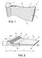
- This hollow blade 1, of the rotor blade type large rope blower has a foot 2 extended by a blade 4 in a radial direction.
- the blade 4 intended to be placed in the vein of circulation of an air flow from the turbomachine, is provided with two outer surfaces 6 and 8, respectively called extrados surface 6 and surface of intrados 8, connected by a leading edge 10 and a trailing edge 12.
- Figure 2 shows an external part 14 of a dawn preform, such as that intended to be obtained following a step of producing two pieces 14, during the implementation of the method of manufacture according to the present invention.
- This external part 14 has a part foot 16 of significant and variable thickness, which is extended in a radial direction by a party 18.
- the foot part 16 has an internal radial portion 20 of a medium thickness E high, this portion 20 being extended radially externally by a outer radial portion 22 of an average thickness e lower than the average thickness E.
- the inner radial portion 20 is subsequently intended to ensure the setting of dawn in a rotor disk of the turbomachine, in particular thanks to the projection portion 23a integral with a central portion 23b arranged in the extension of the outer radial portion 22 of the foot portion 16.
- the pale part 18 of the piece external 14 has a radially inner end 24 of a thickness e 'substantially equal to the thickness average e, and a radially outer end 26 of a thickness e "smaller than the thickness e '.
- the pale portion 18 of Exhibit 14 is of substantially homogeneous thickness.
- the radially inner end 24 establishes the junction between the blade portion 18 and the outer radial portion 22 of the foot part 16 of the outer piece 14, as schematically shows the fictitious plane of junction P shown in Figure 2.
- a step of producing the two external parts 14 of the blade preform is made in the manner described above, with reference to Figures 3a to 3c. AT this title, it is noted that the two external parts 14 being usually done in the same way, only the manufacture of one of these two pieces 14 goes so be presented.
- a primary element 28 presenting a inner surface 28a and an outer surface 28b.
- the primary element 28 is manufactured so that it only forms the blade portion 18 of this outer piece 14. Therefore, the thickness of this primary element 28 is substantially homogeneous, and the technique of making the latter by Forging, preferably by rolling, is therefore particularly adapted, and quite optimized in terms of material costs and machining costs. This can be explained by the fact that the element supply necessary for its manufacture may easily have dimensions close to final dimensions that must present this same element 28.
- the secondary element 34 therefore comprises a portion 36 of significant thickness and similar to the serving internal radial 20 shown in FIG. than a part 38 of smaller thickness similar to the outer radial portion 22 shown on this same Figure 2.
- Element 34 can therefore easily be made by spinning in any other technique of forging, this preferred spinning / extrusion technique proven low cost consisting of, from a billet of matter and through a die appropriate, to create a profile of the element secondary 34 having the desired geometry. Of this way, with such a technique, it is possible to make secondary elements 34 one to the following the others, by simply slicing pieces of great length.
- This assembly can then be done by welding, by contacting a radial surface internal 40 of the primary element 28 with a surface external radial 42 of the secondary element 34.
- surfaces 40 and 42 are substantially flat and jointly define a flat contact area 44, disposed substantially at a location identical to that of the fictitious junction plane P represented on the FIG. 2, with respect to the foot parts 16 and the blade 18 of the outer part 14.
- the operation of the secondary element 34 on the element primary 28 is preferably performed by welding by linear friction, or by friction welding stir welding ".
- These known welding techniques advantageously allow the welded zone to retain metallurgical characteristics compatible with diffusion welding technique and that of superplastic inflation, and ensure mechanical properties in accordance with the specifications of the finished external part.
- this welding operation can be followed by a machining operation of geometric reconditioning of the welded zone, in the goal of obtaining an external part 14 including a surface 14a and an outer surface 14b have the expected geometry.
- the preform 30 can be performed conventionally using two external parts 14 identical to the internal faces 14a grooved, or with three pieces two identical external parts 14 have substantially smooth internal surfaces 14a in contact with a third intermediate piece (no represented), intended to constitute subsequently a stiffener.
- the preform 30 is only consisting of two external parts identical 14, once they are manufactured as described above, they are then welded together by diffusion, in a manner similar to that encountered in the prior art to perform the assembly of the various constituent parts of the preform.
- the diffusion welding operation is preceded an operation to deposit anti-diffusion barriers (not shown) in a specific barriers being arranged at the level of the surfaces internal contacts 14a external parts 14.
- the assembly step by welding by diffusion of two pieces 14 is then carried out from a analogous and classical way, by interposing this piece intermediate between the two outer pieces 14 so that these are each fixed by welding by diffusion to the intermediate piece.
- the dawn preform 30 Following the completion stage of the dawn preform 30 which has just been described, it is then proceeded to conventional steps aimed at all first to put in the aerodynamic profile the preform 30, so that it has a shape substantially twisted as shown in Figure 3e. Then, always in a known way, a step of inflation by gas pressure and forming superplastic makes it possible to get the dawn 1 such that that represented in FIG. 1, this step being usually followed by a final machining intended for give the dawn 1 rigorously the profile desired aerodynamics.
- Figure 4 shows an external part 14 obtained following the implementation of the realization of the two external parts 14, during the implementation of the manufacturing process according to a second preferred embodiment of the present invention.
- a primary element 128 is similar to the one encountered for the realization of the primary element 28, unlike that the primary element 128 is intended to form the portion 18 of the outer piece 14, as well as a central portion of the foot part 16 of this same Exhibit 14.
- the central part of the foot part 16, not referenced on the Figure 2 should be understood as substantially consisting of the entire outer radial portion 22 as well than the central portion 23b of the radial portion internal 20.
- the primary element 128 therefore extends over the entire radial length of part 14, while keeping a homogeneous thickness. Therefore, here still, the technique of obtaining pieces 128 by rolling is therefore particularly suitable, and everything to optimized in terms of material costs and machining costs, insofar as the elements supplies necessary for the manufacture of these 128 external parts can easily have dimensions close to the final dimensions that must present these same pieces 128.
- a unique secondary element 134 is manufactured in such a way that forms a portion of the foot portion 16 of the piece 14, when assembled on the primary element 128.
- the element secondary 134 is manufactured and assembled on a surface 128b of the primary element 128, the latter having a substantially parallelepipedic shape and being intended to constitute the projection part 23a of the inner radial portion 20 of the foot portion 16, shown in Figure 2.
- the simplified geometry of the secondary element 134 by compared to that of secondary element 34 allows further facilitate the realization of this element, preferably always using the spinning technique described above.
- the primary element 128 and the secondary element 134 were simultaneously made, preferably in a titanium alloy, it is then assembled so as to to obtain substantially the geometry of the external part 14, as shown in Figure 4.
- the operation of the secondary element 134 on the element primary 128 is preferably carried out by linear friction welding or welding by friction stir welding.
- the two external pieces 14 made as indicated above are then conventionally assembled by diffusion welding, in order to obtain the preform 30 desired.
- Figure 5 shows an external part 14 obtained following the implementation of the realization of the two external parts 14, during the implementation of the manufacturing process according to a third preferred embodiment of this invention.
- the primary element 128 is realized in a similar way to that encountered in the second preferred embodiment, so that it form the blade portion 18 of the piece 14, as well as a central portion of the foot part 16 of this same external part 14.
- the primary element 128 therefore extends also over the entire radial length of part 14, while maintaining a homogeneous thickness.
- the third preferred embodiment provides that two 234 secondary elements are manufactured and assembled on this surface 128b, always so as to obtain a form substantially identical to that of the part of projection 23a of the inner radial portion 20 of the foot part 16.
- the division into two elements 234 of the projection part 23a allows to facilitate friction welding operations linear of these elements 234 on the primary element 128, and therefore require an industrial apparatus less efficient than that required for the implementation of the second preferred embodiment of the method according to the present invention.
Landscapes
- Engineering & Computer Science (AREA)
- Mechanical Engineering (AREA)
- Architecture (AREA)
- General Engineering & Computer Science (AREA)
- Pressure Welding/Diffusion-Bonding (AREA)
- Structures Of Non-Positive Displacement Pumps (AREA)
- Turbine Rotor Nozzle Sealing (AREA)
- Forging (AREA)
Abstract
- la fabrication par forgeage d'un élément primaire (28) constituant au moins une partie pale de la pièce externe,
- la fabrication par forgeage d'au moins un élément secondaire (34) destiné à former au moins partiellement une partie pied de la pièce externe, et
- l'assemblage de chaque élément secondaire sur l'élément primaire afin d'obtenir la pièce externe.
Description
- la fabrication par forgeage, de préférence par laminage d'un élément primaire constituant au moins la partie pale de la pièce externe,
- la fabrication par forgeage, de préférence par filage, d'au moins un élément secondaire destiné à former au moins partiellement la partie pied de la pièce externe, et
- l'assemblage de chaque élément secondaire sur l'élément primaire afin d'obtenir la pièce externe.
- mise au profil aérodynamique de la préforme, et
- gonflage par pression gazeuse et formage superplastique de la préforme mise au profil aérodynamique.
- la figure 1 représente une vue en perspective d'une aube creuse classique pour turbomachine,
- la figure 2 représente une vue schématique en perspective d'une pièce externe d'une préforme d'aube, obtenue lors de la mise en oeuvre de l'étape de réalisation des deux pièces externes du procédé de fabrication selon la présente invention,
- les figures 3a à 3e illustrent schématiquement des étapes d'un premier mode de réalisation préféré du procédé de fabrication selon la présente invention, et
- les figures 4 et 5 représentent une pièce externe de préforme d'aube, obtenue lors de la mise en oeuvre de l'étape de réalisation des deux pièces externes du procédé de fabrication, respectivement selon un second mode et un troisième mode de réalisation préférés de la présente invention.
Claims (7)
- Procédé de fabrication d'une aube creuse pour turbomachine comprenant un pied (2) et une pale (4), ledit procédé comportant une étape de réalisation de deux pièces externes (14) présentant chacune une partie pale (18) et une partie pied (16) et étant destinées à former au moins partiellement une préforme d'aube (30), le procédé comprenant en outre une étape d'assemblage par soudage par diffusion des deux pièces externes (14) de manière à obtenir ladite préforme d'aube (30), caractérisé en ce que l'étape de réalisation des deux pièces externes (14) comprend, pour chacune desdites pièces externes (14), les opérations suivantes :la fabrication par forgeage d'un élément primaire (28,128) constituant au moins ladite partie pale (18) de la pièce externe (14),la fabrication par forgeage d'au moins un élément secondaire (34,134,234) destiné à former au moins partiellement ladite partie pied (16) de la pièce externe (14), etl'assemblage de chaque élément secondaire (34,134,234) sur l'élément primaire (28,128) afin d'obtenir ladite pièce externe (14).
- Procédé de fabrication selon la revendication 1, caractérisé en ce que l'opération d'assemblage de chaque élément secondaire (34,134,234) sur l'élément primaire (28,128) est mise en oeuvre à l'aide d'une technique prise parmi le groupe constitué du soudage par friction linéaire, et du soudage par « friction stir welding ».
- Procédé de fabrication selon la revendication 1 ou la revendication 2, caractérisé en ce que l'étape d'assemblage par soudage par diffusion des deux pièces externes (14) de manière à obtenir ladite préforme d'aube (30) est suivie des étapes suivantes :mise au profil aérodynamique de ladite préforme (30), etgonflage par pression gazeuse et formage superplastique de ladite préforme (30) mise au profil aérodynamique.
- Procédé de fabrication selon l'une quelconque des revendications précédentes, caractérisé en ce que chaque élément secondaire (34,134,234) destiné à former au moins partiellement ladite partie pied (16) de chacune des deux pièces externes (14) est réalisé par filage.
- Procédé de fabrication selon l'une quelconque des revendications précédentes, caractérisé en ce que pour chacune des deux pièces externes (14), ledit procédé est mis en oeuvre de telle sorte que l'élément primaire (28) est fabriqué de manière à former uniquement ladite partie pale (18) de la pièce externe (14), et de telle sorte qu'un unique élément secondaire (34) est fabriqué de façon à former intégralement ladite partie pied (16) de cette préforme (14).
- Procédé de fabrication selon l'une quelconque des revendications 1 à 4, caractérisé en ce que pour chacune des deux pièces externes (14), il est mis en oeuvre de telle sorte que l'élément primaire (128) est fabriqué de manière à former ladite partie pale (18) de la pièce externe (14) ainsi qu'une portion centrale de ladite partie pied (16) de cette pièce externe (14), et de telle sorte qu'au moins un élément secondaire (134,234) est fabriqué de façon à former une portion de ladite partie pied (16) de la pièce externe (14), lorsqu'il est assemblé sur l'élément primaire (128).
- Procédé de fabrication selon la revendication 6, caractérisé en ce que pour chacune des deux pièces externes (14), l'élément primaire (128) est fabriqué de manière à présenter une surface externe (128b), et en ce que lesdits éléments secondaires (134,234) sont assemblés sur ladite surface externe (128b) de cet élément primaire (128).
Applications Claiming Priority (2)
| Application Number | Priority Date | Filing Date | Title |
|---|---|---|---|
| FR0350183 | 2003-05-27 | ||
| FR0350183A FR2855439B1 (fr) | 2003-05-27 | 2003-05-27 | Procede de fabrication d'une aube creuse pour turbomachine. |
Publications (2)
| Publication Number | Publication Date |
|---|---|
| EP1481756A1 true EP1481756A1 (fr) | 2004-12-01 |
| EP1481756B1 EP1481756B1 (fr) | 2011-02-02 |
Family
ID=33104532
Family Applications (1)
| Application Number | Title | Priority Date | Filing Date |
|---|---|---|---|
| EP04102300A Expired - Lifetime EP1481756B1 (fr) | 2003-05-27 | 2004-05-25 | Procédé de fabrication d'une aube creuse pour turbomachine |
Country Status (9)
| Country | Link |
|---|---|
| US (1) | US7334332B2 (fr) |
| EP (1) | EP1481756B1 (fr) |
| JP (1) | JP2004353669A (fr) |
| CA (1) | CA2467810C (fr) |
| DE (1) | DE602004031276D1 (fr) |
| ES (1) | ES2359913T3 (fr) |
| FR (1) | FR2855439B1 (fr) |
| RU (1) | RU2349437C2 (fr) |
| UA (1) | UA84260C2 (fr) |
Cited By (4)
| Publication number | Priority date | Publication date | Assignee | Title |
|---|---|---|---|---|
| WO2011064406A1 (fr) * | 2009-11-30 | 2011-06-03 | Snecma | Procede de realisation d' un renfort metallique d' aube de turbomachine |
| EP2226134A3 (fr) * | 2009-03-04 | 2014-01-08 | Rolls-Royce plc | Procédé de fabrication d'une surface portante |
| EP2226133A3 (fr) * | 2009-03-04 | 2014-01-08 | Rolls-Royce plc | Procédé de fabrication d'une surface portante |
| EP3783196A1 (fr) * | 2019-08-02 | 2021-02-24 | Raytheon Technologies Corporation | Profil aérodynamique hybride pour un moteur à turbine à gaz |
Families Citing this family (18)
| Publication number | Priority date | Publication date | Assignee | Title |
|---|---|---|---|---|
| FR2855439B1 (fr) | 2003-05-27 | 2006-07-14 | Snecma Moteurs | Procede de fabrication d'une aube creuse pour turbomachine. |
| US7398911B2 (en) * | 2003-12-16 | 2008-07-15 | The Boeing Company | Structural assemblies and preforms therefor formed by friction welding |
| US7225967B2 (en) * | 2003-12-16 | 2007-06-05 | The Boeing Company | Structural assemblies and preforms therefor formed by linear friction welding |
| US7380321B2 (en) * | 2006-03-28 | 2008-06-03 | The Boeing Company | Machining technique with selective and localized placement of tooling material |
| US20100068550A1 (en) * | 2007-06-15 | 2010-03-18 | United Technologies Corporation | Hollow structures formed with friction stir welding |
| US20080308610A1 (en) * | 2007-06-15 | 2008-12-18 | United Technologies Corporation | Hollow structures formed with friction stir welding |
| US20080311421A1 (en) * | 2007-06-15 | 2008-12-18 | United Technologies Corporation | Friction stir welded structures derived from AL-RE-TM alloys |
| US20080308197A1 (en) * | 2007-06-15 | 2008-12-18 | United Technologies Corporation | Secondary processing of structures derived from AL-RE-TM alloys |
| US7762447B2 (en) * | 2008-03-20 | 2010-07-27 | Ut-Battelle, Llc | Multiple pass and multiple layer friction stir welding and material enhancement processes |
| FR2929149B1 (fr) * | 2008-03-25 | 2010-04-16 | Snecma | Procede de fabrication d'une aube creuse |
| GB0913655D0 (en) * | 2009-08-06 | 2009-09-16 | Rolls Royce Plc | A method of friction welding |
| RU2450881C1 (ru) * | 2010-12-27 | 2012-05-20 | Открытое акционерное общество Научно-производственное объединение "Центральный научно-исследовательский институт технологии машиностроения" ОАО НПО "ЦНИИТМАШ" | Способ изготовления лопатки |
| JP5936530B2 (ja) | 2012-12-19 | 2016-06-22 | 三菱日立パワーシステムズ株式会社 | タービンの動翼の製造方法 |
| CN103586634A (zh) * | 2013-11-01 | 2014-02-19 | 哈尔滨汽轮机厂有限责任公司 | 一种燃气轮机透平空心静叶片导流芯的制备方法 |
| FR3036640B1 (fr) * | 2015-05-26 | 2017-05-12 | Snecma | Procede de fabrication d'une aube de turbomachine en tial |
| GB201701236D0 (en) * | 2017-01-25 | 2017-03-08 | Rolls Royce Plc | Bladed disc and method of manufacturing the same |
| US10525548B2 (en) | 2017-07-20 | 2020-01-07 | General Electric Company | Friction welding method |
| DE102019202054A1 (de) * | 2019-02-15 | 2020-08-20 | Siemens Aktiengesellschaft | Laufschaufel für eine thermische Rotationsmaschine sowie Verfahren zum Herstellen einer solchen Laufschaufel |
Citations (5)
| Publication number | Priority date | Publication date | Assignee | Title |
|---|---|---|---|---|
| GB817660A (en) * | 1955-05-27 | 1959-08-06 | Bristol Aero Engines Ltd | Improvements in or relating to blades for gas turbines |
| US3768147A (en) * | 1971-12-20 | 1973-10-30 | Gen Electric | Method of friction welding |
| US4583274A (en) * | 1982-03-01 | 1986-04-22 | Trw Inc. | Method of making an airfoil |
| US5636440A (en) * | 1994-09-07 | 1997-06-10 | Societe Nationale D'etude Et De Construction De Moteurs D'aviation "Snecma" | Process for manufacturing a hollow blade for a turbo-machine |
| US6331217B1 (en) * | 1997-10-27 | 2001-12-18 | Siemens Westinghouse Power Corporation | Turbine blades made from multiple single crystal cast superalloy segments |
Family Cites Families (25)
| Publication number | Priority date | Publication date | Assignee | Title |
|---|---|---|---|---|
| US1516556A (en) * | 1922-11-21 | 1924-11-25 | Gen Electric | Method of manufacturing turbine blades |
| CH238023A (de) | 1943-07-31 | 1945-06-15 | Sulzer Ag | Schaufel für Turbomaschinen und Verfahren zu deren Herstellung. |
| FR970578A (fr) | 1948-08-19 | 1951-01-05 | Bohler & Cie Ag Geb | Aubes creuses pour turbines, notamment pour turbines à gaz, et procédé pour leur fabrication |
| US2767460A (en) * | 1950-02-08 | 1956-10-23 | Robbins Engineering Company | Turbine blade and method of making same |
| US3045967A (en) * | 1952-04-12 | 1962-07-24 | Stalker Corp | Hollow blades and manufacture thereof |
| GB789659A (en) | 1956-08-31 | 1958-01-22 | Gen Motors Corp | Improvements relating to the manufacture of metal blades having curved surfaces |
| US3196526A (en) * | 1961-06-13 | 1965-07-27 | Bristol Siddeley Engines Ltd | Method of making turbine blades |
| US3653110A (en) * | 1970-01-05 | 1972-04-04 | North American Rockwell | Method of fabricating hollow blades |
| US3982854A (en) * | 1971-12-20 | 1976-09-28 | General Electric Company | Friction welded metallic turbomachinery blade element |
| US3936920A (en) * | 1972-08-14 | 1976-02-10 | Tre Corporation | Aerodynamic shell structure with fittings and method for fabricating same |
| US4882823A (en) * | 1988-01-27 | 1989-11-28 | Ontario Technologies Corp. | Superplastic forming diffusion bonding process |
| SU1722747A1 (ru) * | 1990-03-07 | 1992-03-30 | Институт проблем сверхпластичности металлов АН СССР | Способ изготовлени изделий |
| US5063662A (en) * | 1990-03-22 | 1991-11-12 | United Technologies Corporation | Method of forming a hollow blade |
| US5269058A (en) * | 1992-12-16 | 1993-12-14 | General Electric Company | Design and processing method for manufacturing hollow airfoils |
| US5429877A (en) * | 1993-10-20 | 1995-07-04 | The United States Of America As Represented By The Secretary Of The Air Force | Internally reinforced hollow titanium alloy components |
| US5469618A (en) | 1993-12-06 | 1995-11-28 | General Electric Company | Method for manufacturing hollow airfoils (two-piece concept) |
| US5469681A (en) * | 1994-03-09 | 1995-11-28 | Wu; Ming-Hsin | Vinyl ceiling grid structure |
| GB2306353B (en) * | 1995-10-28 | 1998-10-07 | Rolls Royce Plc | A method of manufacturing a blade |
| FR2754478B1 (fr) * | 1996-10-16 | 1998-11-20 | Snecma | Procede de fabrication d'une aube creuse de turbomachine |
| US6219916B1 (en) * | 1997-12-19 | 2001-04-24 | United Technologies Corporation | Method for linear friction welding and product made by such method |
| US6022191A (en) * | 1998-05-15 | 2000-02-08 | The Moore Company | Fan blade mounting |
| GB0022531D0 (en) | 2000-09-14 | 2000-11-01 | Rolls Royce Plc | A method of manufacturing an article by diffusion bonding |
| GB0100695D0 (en) * | 2001-01-11 | 2001-02-21 | Rolls Royce Plc | a turbomachine blade |
| US6537682B2 (en) | 2001-03-27 | 2003-03-25 | The Boeing Company | Application of friction stir welding to superplastically formed structural assemblies |
| FR2855439B1 (fr) | 2003-05-27 | 2006-07-14 | Snecma Moteurs | Procede de fabrication d'une aube creuse pour turbomachine. |
-
2003
- 2003-05-27 FR FR0350183A patent/FR2855439B1/fr not_active Expired - Fee Related
-
2004
- 2004-05-19 CA CA2467810A patent/CA2467810C/fr not_active Expired - Lifetime
- 2004-05-19 US US10/847,863 patent/US7334332B2/en not_active Expired - Lifetime
- 2004-05-25 EP EP04102300A patent/EP1481756B1/fr not_active Expired - Lifetime
- 2004-05-25 JP JP2004154579A patent/JP2004353669A/ja active Pending
- 2004-05-25 ES ES04102300T patent/ES2359913T3/es not_active Expired - Lifetime
- 2004-05-25 DE DE602004031276T patent/DE602004031276D1/de not_active Expired - Lifetime
- 2004-05-26 RU RU2004116119/02A patent/RU2349437C2/ru active
- 2004-05-27 UA UA20040504058A patent/UA84260C2/ru unknown
Patent Citations (5)
| Publication number | Priority date | Publication date | Assignee | Title |
|---|---|---|---|---|
| GB817660A (en) * | 1955-05-27 | 1959-08-06 | Bristol Aero Engines Ltd | Improvements in or relating to blades for gas turbines |
| US3768147A (en) * | 1971-12-20 | 1973-10-30 | Gen Electric | Method of friction welding |
| US4583274A (en) * | 1982-03-01 | 1986-04-22 | Trw Inc. | Method of making an airfoil |
| US5636440A (en) * | 1994-09-07 | 1997-06-10 | Societe Nationale D'etude Et De Construction De Moteurs D'aviation "Snecma" | Process for manufacturing a hollow blade for a turbo-machine |
| US6331217B1 (en) * | 1997-10-27 | 2001-12-18 | Siemens Westinghouse Power Corporation | Turbine blades made from multiple single crystal cast superalloy segments |
Cited By (6)
| Publication number | Priority date | Publication date | Assignee | Title |
|---|---|---|---|---|
| EP2226134A3 (fr) * | 2009-03-04 | 2014-01-08 | Rolls-Royce plc | Procédé de fabrication d'une surface portante |
| EP2226133A3 (fr) * | 2009-03-04 | 2014-01-08 | Rolls-Royce plc | Procédé de fabrication d'une surface portante |
| WO2011064406A1 (fr) * | 2009-11-30 | 2011-06-03 | Snecma | Procede de realisation d' un renfort metallique d' aube de turbomachine |
| EP3783196A1 (fr) * | 2019-08-02 | 2021-02-24 | Raytheon Technologies Corporation | Profil aérodynamique hybride pour un moteur à turbine à gaz |
| US11248477B2 (en) | 2019-08-02 | 2022-02-15 | Raytheon Technologies Corporation | Hybridized airfoil for a gas turbine engine |
| US11781436B2 (en) | 2019-08-02 | 2023-10-10 | Rtx Corporation | Hybridized airfoil for a gas turbine engine |
Also Published As
| Publication number | Publication date |
|---|---|
| JP2004353669A (ja) | 2004-12-16 |
| UA84260C2 (ru) | 2008-10-10 |
| RU2349437C2 (ru) | 2009-03-20 |
| US20050005445A1 (en) | 2005-01-13 |
| RU2004116119A (ru) | 2006-02-27 |
| CA2467810C (fr) | 2011-12-06 |
| CA2467810A1 (fr) | 2004-11-27 |
| ES2359913T3 (es) | 2011-05-30 |
| DE602004031276D1 (de) | 2011-03-17 |
| FR2855439B1 (fr) | 2006-07-14 |
| US7334332B2 (en) | 2008-02-26 |
| EP1481756B1 (fr) | 2011-02-02 |
| FR2855439A1 (fr) | 2004-12-03 |
Similar Documents
| Publication | Publication Date | Title |
|---|---|---|
| EP1481756B1 (fr) | Procédé de fabrication d'une aube creuse pour turbomachine | |
| EP1462609B1 (fr) | Aube allégée de turbomachine et son procédé de fabrication | |
| EP2844841B1 (fr) | Renfort structurel metallique d'aube en composite de turbomachine | |
| EP2252770B1 (fr) | Aube avec plateforme non axisymetrique | |
| EP0395498B1 (fr) | Aube de stator à calage variable à coupelle rapportée | |
| FR2867095A1 (fr) | Procede de fabrication d'une aube creuse pour turbomachine. | |
| EP1516690B1 (fr) | Procédé de fabrication ou de réparation d'un disque aubage monobloc | |
| EP2254729B1 (fr) | Procédé de fabrication d'une aube creuse | |
| CA2442952C (fr) | Tambour formant en particulier un rotor de turbo machine, compresseur et turbo moteur comprenant un tel tambour | |
| FR2941487A1 (fr) | Aube de turbomachine en materiau composite a pied renforce | |
| EP3253970B1 (fr) | Aube de soufflante | |
| CA2514106C (fr) | Procede de fabrication de pieces constitutives d'une aube creuse par laminage | |
| EP1452741A1 (fr) | Aube en flèche de turboréacteur | |
| WO2009112774A2 (fr) | Aube avec plateforme 3d comportant un bulbe interaubes | |
| FR2926322A1 (fr) | Aube bi-pale avec lames. | |
| EP1481755B1 (fr) | Procédé de fabrication d'une aube creuse pour turbomachine | |
| FR2855441A1 (fr) | Aube creuse pour turbomachine et procede de fabrication d'une telle aube. | |
| EP3607211A1 (fr) | Diffuseur axial renforcé | |
| WO2013088078A1 (fr) | Secteur de redresseur pour un compresseur de turbomachine réalisé par brasage d'une plate-forme de ses aubes sur une virole | |
| FR3118891A1 (fr) | Fabrication d’un injecteur de turbine par fusion laser sur lit de poudre | |
| WO2016038282A1 (fr) | Procédé de réparation d'un rail amont d'un carter de turbine de turbomachine | |
| FR2514072A1 (fr) | Procede de fabrication d'une aube pour moteur a turbine a gaz | |
| FR3067625A1 (fr) | Procede de fabrication d’une aube de rotor pour une turbomachine d’aeronef | |
| FR3127985A1 (fr) | Clinquant pour diminuer les contraintes dans un col de pied d’aube de turbine |
Legal Events
| Date | Code | Title | Description |
|---|---|---|---|
| PUAI | Public reference made under article 153(3) epc to a published international application that has entered the european phase |
Free format text: ORIGINAL CODE: 0009012 |
|
| AK | Designated contracting states |
Kind code of ref document: A1 Designated state(s): AT BE BG CH CY CZ DE DK EE ES FI FR GB GR HU IE IT LI LU MC NL PL PT RO SE SI SK TR |
|
| AX | Request for extension of the european patent |
Extension state: AL HR LT LV MK |
|
| 17P | Request for examination filed |
Effective date: 20050524 |
|
| AKX | Designation fees paid |
Designated state(s): DE ES FR GB IT |
|
| RAP1 | Party data changed (applicant data changed or rights of an application transferred) |
Owner name: SNECMA |
|
| 17Q | First examination report despatched |
Effective date: 20080609 |
|
| GRAP | Despatch of communication of intention to grant a patent |
Free format text: ORIGINAL CODE: EPIDOSNIGR1 |
|
| GRAS | Grant fee paid |
Free format text: ORIGINAL CODE: EPIDOSNIGR3 |
|
| GRAA | (expected) grant |
Free format text: ORIGINAL CODE: 0009210 |
|
| AK | Designated contracting states |
Kind code of ref document: B1 Designated state(s): DE ES FR GB IT |
|
| REG | Reference to a national code |
Ref country code: GB Ref legal event code: FG4D Free format text: NOT ENGLISH |
|
| REF | Corresponds to: |
Ref document number: 602004031276 Country of ref document: DE Date of ref document: 20110317 Kind code of ref document: P |
|
| REG | Reference to a national code |
Ref country code: DE Ref legal event code: R096 Ref document number: 602004031276 Country of ref document: DE Effective date: 20110317 |
|
| REG | Reference to a national code |
Ref country code: ES Ref legal event code: FG2A Ref document number: 2359913 Country of ref document: ES Kind code of ref document: T3 Effective date: 20110530 |
|
| PLBE | No opposition filed within time limit |
Free format text: ORIGINAL CODE: 0009261 |
|
| STAA | Information on the status of an ep patent application or granted ep patent |
Free format text: STATUS: NO OPPOSITION FILED WITHIN TIME LIMIT |
|
| 26N | No opposition filed |
Effective date: 20111103 |
|
| REG | Reference to a national code |
Ref country code: DE Ref legal event code: R097 Ref document number: 602004031276 Country of ref document: DE Effective date: 20111103 |
|
| PGFP | Annual fee paid to national office [announced via postgrant information from national office to epo] |
Ref country code: ES Payment date: 20120508 Year of fee payment: 9 |
|
| REG | Reference to a national code |
Ref country code: ES Ref legal event code: FD2A Effective date: 20140606 |
|
| PG25 | Lapsed in a contracting state [announced via postgrant information from national office to epo] |
Ref country code: ES Free format text: LAPSE BECAUSE OF NON-PAYMENT OF DUE FEES Effective date: 20130526 |
|
| REG | Reference to a national code |
Ref country code: FR Ref legal event code: PLFP Year of fee payment: 13 |
|
| REG | Reference to a national code |
Ref country code: FR Ref legal event code: PLFP Year of fee payment: 14 |
|
| REG | Reference to a national code |
Ref country code: FR Ref legal event code: CD Owner name: SNECMA, FR Effective date: 20170713 |
|
| REG | Reference to a national code |
Ref country code: FR Ref legal event code: PLFP Year of fee payment: 15 |
|
| PGFP | Annual fee paid to national office [announced via postgrant information from national office to epo] |
Ref country code: IT Payment date: 20230420 Year of fee payment: 20 Ref country code: FR Payment date: 20230420 Year of fee payment: 20 Ref country code: DE Payment date: 20230419 Year of fee payment: 20 |
|
| PGFP | Annual fee paid to national office [announced via postgrant information from national office to epo] |
Ref country code: GB Payment date: 20230420 Year of fee payment: 20 |
|
| REG | Reference to a national code |
Ref country code: DE Ref legal event code: R071 Ref document number: 602004031276 Country of ref document: DE |
|
| REG | Reference to a national code |
Ref country code: GB Ref legal event code: PE20 Expiry date: 20240524 |
|
| PG25 | Lapsed in a contracting state [announced via postgrant information from national office to epo] |
Ref country code: GB Free format text: LAPSE BECAUSE OF EXPIRATION OF PROTECTION Effective date: 20240524 |
|
| PG25 | Lapsed in a contracting state [announced via postgrant information from national office to epo] |
Ref country code: GB Free format text: LAPSE BECAUSE OF EXPIRATION OF PROTECTION Effective date: 20240524 |