EP1481719A2 - Engine exhaust gas treatment system and exhaust gas treatment process - Google Patents
Engine exhaust gas treatment system and exhaust gas treatment process Download PDFInfo
- Publication number
- EP1481719A2 EP1481719A2 EP20040012440 EP04012440A EP1481719A2 EP 1481719 A2 EP1481719 A2 EP 1481719A2 EP 20040012440 EP20040012440 EP 20040012440 EP 04012440 A EP04012440 A EP 04012440A EP 1481719 A2 EP1481719 A2 EP 1481719A2
- Authority
- EP
- European Patent Office
- Prior art keywords
- exhaust gas
- urea solution
- ammonia
- urea
- heater
- Prior art date
- Legal status (The legal status is an assumption and is not a legal conclusion. Google has not performed a legal analysis and makes no representation as to the accuracy of the status listed.)
- Withdrawn
Links
Images




Classifications
-
- F—MECHANICAL ENGINEERING; LIGHTING; HEATING; WEAPONS; BLASTING
- F01—MACHINES OR ENGINES IN GENERAL; ENGINE PLANTS IN GENERAL; STEAM ENGINES
- F01N—GAS-FLOW SILENCERS OR EXHAUST APPARATUS FOR MACHINES OR ENGINES IN GENERAL; GAS-FLOW SILENCERS OR EXHAUST APPARATUS FOR INTERNAL-COMBUSTION ENGINES
- F01N3/00—Exhaust or silencing apparatus having means for purifying, rendering innocuous, or otherwise treating exhaust
- F01N3/08—Exhaust or silencing apparatus having means for purifying, rendering innocuous, or otherwise treating exhaust for rendering innocuous
- F01N3/10—Exhaust or silencing apparatus having means for purifying, rendering innocuous, or otherwise treating exhaust for rendering innocuous by thermal or catalytic conversion of noxious components of exhaust
- F01N3/18—Exhaust or silencing apparatus having means for purifying, rendering innocuous, or otherwise treating exhaust for rendering innocuous by thermal or catalytic conversion of noxious components of exhaust characterised by methods of operation; Control
- F01N3/20—Exhaust or silencing apparatus having means for purifying, rendering innocuous, or otherwise treating exhaust for rendering innocuous by thermal or catalytic conversion of noxious components of exhaust characterised by methods of operation; Control specially adapted for catalytic conversion
- F01N3/206—Adding periodically or continuously substances to exhaust gases for promoting purification, e.g. catalytic material in liquid form, NOx reducing agents
- F01N3/208—Control of selective catalytic reduction [SCR], e.g. by adjusting the dosing of reducing agent
-
- B—PERFORMING OPERATIONS; TRANSPORTING
- B01—PHYSICAL OR CHEMICAL PROCESSES OR APPARATUS IN GENERAL
- B01D—SEPARATION
- B01D53/00—Separation of gases or vapours; Recovering vapours of volatile solvents from gases; Chemical or biological purification of waste gases, e.g. engine exhaust gases, smoke, fumes, flue gases, aerosols
- B01D53/34—Chemical or biological purification of waste gases
- B01D53/92—Chemical or biological purification of waste gases of engine exhaust gases
- B01D53/94—Chemical or biological purification of waste gases of engine exhaust gases by catalytic processes
- B01D53/9404—Removing only nitrogen compounds
- B01D53/9409—Nitrogen oxides
- B01D53/9431—Processes characterised by a specific device
-
- B—PERFORMING OPERATIONS; TRANSPORTING
- B01—PHYSICAL OR CHEMICAL PROCESSES OR APPARATUS IN GENERAL
- B01D—SEPARATION
- B01D53/00—Separation of gases or vapours; Recovering vapours of volatile solvents from gases; Chemical or biological purification of waste gases, e.g. engine exhaust gases, smoke, fumes, flue gases, aerosols
- B01D53/34—Chemical or biological purification of waste gases
- B01D53/92—Chemical or biological purification of waste gases of engine exhaust gases
- B01D53/94—Chemical or biological purification of waste gases of engine exhaust gases by catalytic processes
- B01D53/9495—Controlling the catalytic process
-
- B—PERFORMING OPERATIONS; TRANSPORTING
- B01—PHYSICAL OR CHEMICAL PROCESSES OR APPARATUS IN GENERAL
- B01F—MIXING, e.g. DISSOLVING, EMULSIFYING OR DISPERSING
- B01F23/00—Mixing according to the phases to be mixed, e.g. dispersing or emulsifying
- B01F23/20—Mixing gases with liquids
- B01F23/21—Mixing gases with liquids by introducing liquids into gaseous media
- B01F23/213—Mixing gases with liquids by introducing liquids into gaseous media by spraying or atomising of the liquids
- B01F23/2132—Mixing gases with liquids by introducing liquids into gaseous media by spraying or atomising of the liquids using nozzles
-
- B—PERFORMING OPERATIONS; TRANSPORTING
- B01—PHYSICAL OR CHEMICAL PROCESSES OR APPARATUS IN GENERAL
- B01F—MIXING, e.g. DISSOLVING, EMULSIFYING OR DISPERSING
- B01F25/00—Flow mixers; Mixers for falling materials, e.g. solid particles
- B01F25/10—Mixing by creating a vortex flow, e.g. by tangential introduction of flow components
-
- B—PERFORMING OPERATIONS; TRANSPORTING
- B01—PHYSICAL OR CHEMICAL PROCESSES OR APPARATUS IN GENERAL
- B01F—MIXING, e.g. DISSOLVING, EMULSIFYING OR DISPERSING
- B01F25/00—Flow mixers; Mixers for falling materials, e.g. solid particles
- B01F25/30—Injector mixers
- B01F25/32—Injector mixers wherein the additional components are added in a by-pass of the main flow
-
- F—MECHANICAL ENGINEERING; LIGHTING; HEATING; WEAPONS; BLASTING
- F01—MACHINES OR ENGINES IN GENERAL; ENGINE PLANTS IN GENERAL; STEAM ENGINES
- F01N—GAS-FLOW SILENCERS OR EXHAUST APPARATUS FOR MACHINES OR ENGINES IN GENERAL; GAS-FLOW SILENCERS OR EXHAUST APPARATUS FOR INTERNAL-COMBUSTION ENGINES
- F01N13/00—Exhaust or silencing apparatus characterised by constructional features
- F01N13/08—Other arrangements or adaptations of exhaust conduits
-
- F—MECHANICAL ENGINEERING; LIGHTING; HEATING; WEAPONS; BLASTING
- F01—MACHINES OR ENGINES IN GENERAL; ENGINE PLANTS IN GENERAL; STEAM ENGINES
- F01N—GAS-FLOW SILENCERS OR EXHAUST APPARATUS FOR MACHINES OR ENGINES IN GENERAL; GAS-FLOW SILENCERS OR EXHAUST APPARATUS FOR INTERNAL-COMBUSTION ENGINES
- F01N3/00—Exhaust or silencing apparatus having means for purifying, rendering innocuous, or otherwise treating exhaust
- F01N3/08—Exhaust or silencing apparatus having means for purifying, rendering innocuous, or otherwise treating exhaust for rendering innocuous
- F01N3/10—Exhaust or silencing apparatus having means for purifying, rendering innocuous, or otherwise treating exhaust for rendering innocuous by thermal or catalytic conversion of noxious components of exhaust
- F01N3/24—Exhaust or silencing apparatus having means for purifying, rendering innocuous, or otherwise treating exhaust for rendering innocuous by thermal or catalytic conversion of noxious components of exhaust characterised by constructional aspects of converting apparatus
- F01N3/28—Construction of catalytic reactors
- F01N3/2892—Exhaust flow directors or the like, e.g. upstream of catalytic device
-
- F—MECHANICAL ENGINEERING; LIGHTING; HEATING; WEAPONS; BLASTING
- F01—MACHINES OR ENGINES IN GENERAL; ENGINE PLANTS IN GENERAL; STEAM ENGINES
- F01N—GAS-FLOW SILENCERS OR EXHAUST APPARATUS FOR MACHINES OR ENGINES IN GENERAL; GAS-FLOW SILENCERS OR EXHAUST APPARATUS FOR INTERNAL-COMBUSTION ENGINES
- F01N2470/00—Structure or shape of exhaust gas passages, pipes or tubes
- F01N2470/24—Concentric tubes or tubes being concentric to housing, e.g. telescopically assembled
-
- F—MECHANICAL ENGINEERING; LIGHTING; HEATING; WEAPONS; BLASTING
- F01—MACHINES OR ENGINES IN GENERAL; ENGINE PLANTS IN GENERAL; STEAM ENGINES
- F01N—GAS-FLOW SILENCERS OR EXHAUST APPARATUS FOR MACHINES OR ENGINES IN GENERAL; GAS-FLOW SILENCERS OR EXHAUST APPARATUS FOR INTERNAL-COMBUSTION ENGINES
- F01N2560/00—Exhaust systems with means for detecting or measuring exhaust gas components or characteristics
- F01N2560/02—Exhaust systems with means for detecting or measuring exhaust gas components or characteristics the means being an exhaust gas sensor
- F01N2560/026—Exhaust systems with means for detecting or measuring exhaust gas components or characteristics the means being an exhaust gas sensor for measuring or detecting NOx
-
- F—MECHANICAL ENGINEERING; LIGHTING; HEATING; WEAPONS; BLASTING
- F01—MACHINES OR ENGINES IN GENERAL; ENGINE PLANTS IN GENERAL; STEAM ENGINES
- F01N—GAS-FLOW SILENCERS OR EXHAUST APPARATUS FOR MACHINES OR ENGINES IN GENERAL; GAS-FLOW SILENCERS OR EXHAUST APPARATUS FOR INTERNAL-COMBUSTION ENGINES
- F01N2560/00—Exhaust systems with means for detecting or measuring exhaust gas components or characteristics
- F01N2560/06—Exhaust systems with means for detecting or measuring exhaust gas components or characteristics the means being a temperature sensor
-
- F—MECHANICAL ENGINEERING; LIGHTING; HEATING; WEAPONS; BLASTING
- F01—MACHINES OR ENGINES IN GENERAL; ENGINE PLANTS IN GENERAL; STEAM ENGINES
- F01N—GAS-FLOW SILENCERS OR EXHAUST APPARATUS FOR MACHINES OR ENGINES IN GENERAL; GAS-FLOW SILENCERS OR EXHAUST APPARATUS FOR INTERNAL-COMBUSTION ENGINES
- F01N2560/00—Exhaust systems with means for detecting or measuring exhaust gas components or characteristics
- F01N2560/07—Exhaust systems with means for detecting or measuring exhaust gas components or characteristics the means being an exhaust gas flow rate or velocity meter or sensor, intake flow meters only when exclusively used to determine exhaust gas parameters
-
- F—MECHANICAL ENGINEERING; LIGHTING; HEATING; WEAPONS; BLASTING
- F01—MACHINES OR ENGINES IN GENERAL; ENGINE PLANTS IN GENERAL; STEAM ENGINES
- F01N—GAS-FLOW SILENCERS OR EXHAUST APPARATUS FOR MACHINES OR ENGINES IN GENERAL; GAS-FLOW SILENCERS OR EXHAUST APPARATUS FOR INTERNAL-COMBUSTION ENGINES
- F01N2570/00—Exhaust treating apparatus eliminating, absorbing or adsorbing specific elements or compounds
- F01N2570/14—Nitrogen oxides
-
- F—MECHANICAL ENGINEERING; LIGHTING; HEATING; WEAPONS; BLASTING
- F01—MACHINES OR ENGINES IN GENERAL; ENGINE PLANTS IN GENERAL; STEAM ENGINES
- F01N—GAS-FLOW SILENCERS OR EXHAUST APPARATUS FOR MACHINES OR ENGINES IN GENERAL; GAS-FLOW SILENCERS OR EXHAUST APPARATUS FOR INTERNAL-COMBUSTION ENGINES
- F01N2610/00—Adding substances to exhaust gases
- F01N2610/02—Adding substances to exhaust gases the substance being ammonia or urea
-
- F—MECHANICAL ENGINEERING; LIGHTING; HEATING; WEAPONS; BLASTING
- F01—MACHINES OR ENGINES IN GENERAL; ENGINE PLANTS IN GENERAL; STEAM ENGINES
- F01N—GAS-FLOW SILENCERS OR EXHAUST APPARATUS FOR MACHINES OR ENGINES IN GENERAL; GAS-FLOW SILENCERS OR EXHAUST APPARATUS FOR INTERNAL-COMBUSTION ENGINES
- F01N2610/00—Adding substances to exhaust gases
- F01N2610/08—Adding substances to exhaust gases with prior mixing of the substances with a gas, e.g. air
-
- F—MECHANICAL ENGINEERING; LIGHTING; HEATING; WEAPONS; BLASTING
- F01—MACHINES OR ENGINES IN GENERAL; ENGINE PLANTS IN GENERAL; STEAM ENGINES
- F01N—GAS-FLOW SILENCERS OR EXHAUST APPARATUS FOR MACHINES OR ENGINES IN GENERAL; GAS-FLOW SILENCERS OR EXHAUST APPARATUS FOR INTERNAL-COMBUSTION ENGINES
- F01N2610/00—Adding substances to exhaust gases
- F01N2610/10—Adding substances to exhaust gases the substance being heated, e.g. by heating tank or supply line of the added substance
- F01N2610/102—Adding substances to exhaust gases the substance being heated, e.g. by heating tank or supply line of the added substance after addition to exhaust gases, e.g. by a passively or actively heated surface in the exhaust conduit
-
- F—MECHANICAL ENGINEERING; LIGHTING; HEATING; WEAPONS; BLASTING
- F01—MACHINES OR ENGINES IN GENERAL; ENGINE PLANTS IN GENERAL; STEAM ENGINES
- F01N—GAS-FLOW SILENCERS OR EXHAUST APPARATUS FOR MACHINES OR ENGINES IN GENERAL; GAS-FLOW SILENCERS OR EXHAUST APPARATUS FOR INTERNAL-COMBUSTION ENGINES
- F01N2610/00—Adding substances to exhaust gases
- F01N2610/14—Arrangements for the supply of substances, e.g. conduits
- F01N2610/1426—Filtration means
-
- F—MECHANICAL ENGINEERING; LIGHTING; HEATING; WEAPONS; BLASTING
- F01—MACHINES OR ENGINES IN GENERAL; ENGINE PLANTS IN GENERAL; STEAM ENGINES
- F01N—GAS-FLOW SILENCERS OR EXHAUST APPARATUS FOR MACHINES OR ENGINES IN GENERAL; GAS-FLOW SILENCERS OR EXHAUST APPARATUS FOR INTERNAL-COMBUSTION ENGINES
- F01N2610/00—Adding substances to exhaust gases
- F01N2610/14—Arrangements for the supply of substances, e.g. conduits
- F01N2610/1453—Sprayers or atomisers; Arrangement thereof in the exhaust apparatus
- F01N2610/146—Control thereof, e.g. control of injectors or injection valves
-
- F—MECHANICAL ENGINEERING; LIGHTING; HEATING; WEAPONS; BLASTING
- F01—MACHINES OR ENGINES IN GENERAL; ENGINE PLANTS IN GENERAL; STEAM ENGINES
- F01N—GAS-FLOW SILENCERS OR EXHAUST APPARATUS FOR MACHINES OR ENGINES IN GENERAL; GAS-FLOW SILENCERS OR EXHAUST APPARATUS FOR INTERNAL-COMBUSTION ENGINES
- F01N2610/00—Adding substances to exhaust gases
- F01N2610/14—Arrangements for the supply of substances, e.g. conduits
- F01N2610/1473—Overflow or return means for the substances, e.g. conduits or valves for the return path
-
- Y—GENERAL TAGGING OF NEW TECHNOLOGICAL DEVELOPMENTS; GENERAL TAGGING OF CROSS-SECTIONAL TECHNOLOGIES SPANNING OVER SEVERAL SECTIONS OF THE IPC; TECHNICAL SUBJECTS COVERED BY FORMER USPC CROSS-REFERENCE ART COLLECTIONS [XRACs] AND DIGESTS
- Y02—TECHNOLOGIES OR APPLICATIONS FOR MITIGATION OR ADAPTATION AGAINST CLIMATE CHANGE
- Y02A—TECHNOLOGIES FOR ADAPTATION TO CLIMATE CHANGE
- Y02A50/00—TECHNOLOGIES FOR ADAPTATION TO CLIMATE CHANGE in human health protection, e.g. against extreme weather
- Y02A50/20—Air quality improvement or preservation, e.g. vehicle emission control or emission reduction by using catalytic converters
-
- Y—GENERAL TAGGING OF NEW TECHNOLOGICAL DEVELOPMENTS; GENERAL TAGGING OF CROSS-SECTIONAL TECHNOLOGIES SPANNING OVER SEVERAL SECTIONS OF THE IPC; TECHNICAL SUBJECTS COVERED BY FORMER USPC CROSS-REFERENCE ART COLLECTIONS [XRACs] AND DIGESTS
- Y02—TECHNOLOGIES OR APPLICATIONS FOR MITIGATION OR ADAPTATION AGAINST CLIMATE CHANGE
- Y02T—CLIMATE CHANGE MITIGATION TECHNOLOGIES RELATED TO TRANSPORTATION
- Y02T10/00—Road transport of goods or passengers
- Y02T10/10—Internal combustion engine [ICE] based vehicles
- Y02T10/12—Improving ICE efficiencies
Definitions
- the present invention relates to an exhaust gas treatment system and treatment process there of, and more particularly, to an exhaust gas treatment system and process which use urea as a reducing agent and can efficiently remove nitrogen oxide in the exhaust gas even in a low temperature region.
- Nitrogen oxide (hereinafter referred to as NOx) included in the exhaust gas emitted from the diesel engines used in vehicles such as a heavy truck and a bus is a material that can cause photochemical smog. Effluent control of NOx that is to be enhanced for these vehicles urgently needs the installation of an exhaust gas denitration system.
- an exhaust gas cleaning system that utilizes a urea solution as the reducing agent, and includes a NOx reduction catalyst provided in the exhaust pipe to make it possible to obtain a high rate of NOx reduction even in a relatively low temperature region, and is configured to add the urea solution as the reducing agent upstream of NOx reduction catalyst.
- a urea decomposition catalyst is provided between two positions in the longitudinal direction of the exhaust pipe, the position where the urea solution is added and the position where NOx reduction catalyst is provided.
- This pre-step urea decomposing catalyst can decompose the urea solution into ammonia and carbon dioxide.
- the ammonia thus obtained is highly reactive with NOx and enables efficient execution of reduction treatment of NOx to make it possible to reduce and clean NOx in a relatively lower temperature region than for the direct reaction of the urea solution with NOx (see, for example, Japanese Application Patent Laid-open Publication No. 2002-161732 (pp. 2-4, Figure 1)).
- Japanese Application Patent Laid-open Publication No. 2002-89241 describes a denitration system that includes a denitration catalyst in the exhaust gas pipe of the internal combustion engine, and that introduces a reducing agent into the pipe to add the agent in the exhaust gas and then brings the exhaust gas into contact with the denitration catalyst, thereby denitrating the exhaust gas.
- This system comprises a reactor, which can store urea in solid state and zeolite together, a heating means for heating the reactor, and a water vessel for storing water.
- the water vessel introduces the water into the reactor, while the heating means heats the reactor to hydrolyze the urea into ammonia gas that is added into the exhaust gas as the reducing agent.
- a urea SCR system is known as the exhaust gas cleaning system that includes no urea decomposition catalyst of the exhaust gas cleaning system described above (see, for example, Matsuo Odaka, "Challenge for Ultra Low Emission Diesel Engine,” Journal of the Japan Society of Mechanical Engineers, 2002.10, Vol. 105, No. 1007, p.23).
- the first conventional technique provides the urea decomposition catalyst between the position where the urea solution is added and the position where the NOx reduction catalyst is provided and adds (injects) directly the urea solution on the urea decomposition catalyst.
- the urea decomposition catalyst can thus decompose the urea solution into ammonia and carbon dioxide, and the ammonia from decomposition can then react with NOx on the NOx reduction catalyst to denitrate the NOx efficiently.
- One way for this is to ensure a predetermined distance between the injection nozzle and the urea decomposition catalyst in such a way that the exhaust heat of the exhaust gas can heat and help evaporate the urea solution before the solution reaches the urea decomposition catalyst.
- the evaporation of the urea-solution spray injected needs a flue length of, for example, about 1.5 m for a urea solution spray with a droplet diameter of about 100 ⁇ m, and needs a flue length of about 6.2 m for a droplet diameter of about 200 ⁇ m. This may cause a large system that is unsuitable for automobile use.
- the above-described way to obtain an amount of heat from the exhaust heat of the exhaust gas for the evaporation may be effective in view of high exhaust gas temperatures generating a large amount of NOx that needs more urea solution.
- this way can achieve insufficient efficiency of evaporation due to lower temperatures and a smaller amount of the exhaust gas. It is thus difficult to efficiently reduce and clean NOx at lower temperatures such as at the startup.
- the second conventional technique Japanese Application Patent Laid-open Publication No. 2002-89241 is an exhaust gas treatment system that evaporates the urea solution and uses ammonia from the hydrolysis as the reducing agent for the denitration catalyst reaction. If this exhaust gas treatment system is applied to vehicles with diesel engines such as a heavy truck and bus, the evaporation and hydrolysis of the maximum required amount of the urea solution (50 cc/min, 32.5 wt%, 25°C) needs about 2.4 kW of the minimum required amount of heat. It is difficult to obtain such an amount of power from the automobile battery.
- the present invention achieves the above-described objects, generally according to the following concepts.
- the urea solution is atomized and the exhaust gas is used as the carrier gas.
- the heater evaporates the urea solution in the operating area with relatively a smaller amount and lower temperatures of the exhaust gas such as at the startup of the diesel engine. Because smaller amount of NOx is generated in this operating area, less urea solution is to be treated and the heater can have the minimum required capacity and power consumption.
- the heat from the exhaust gas is used to make it possible to evaporate a plenty of urea solution, in case of higher temperatures of the exhaust gas and a plenty of NOx generation.
- the urea solution and exhaust gas are circled and more than one restriction is provided in the flue and evaporator passage to effectively exchange heat between the urea solution and exhaust gas and mix the urea solution with exhaust gas in a space-saving manner.
- An exhaust gas diversion means is provided to make it possible to supply the exhaust gas onto the denitration catalyst over the shortest distance to warm up the denitration catalyst in the shortest time, in the operating area with relatively a smaller amount and lower temperatures of the exhaust gas such as at the startup of the diesel engine.
- the present invention can thus be illustrated as follows.
- FIG. 1 shows the overall configuration of the exhaust gas treatment system of an embodiment according to the present invention.
- the diesel engine 1 determines the fuel injection amount and injection timing based on various signals that are input to the ECU (Electric Control Unit) 2.
- the diesel engine also has a not-shown EGR (exhaust gas recirculation) valve and an intake throttle that is used together with the EGR valve to expand the control region of the EGR rate.
- EGR exhaust gas recirculation
- DPF Diesel Particulate Filter 4 4, which is a diesel particulate removal device, resides in the flue 3 that is an exhaust passage of the exhaust gas 22 emitted from the diesel engine 1. Downstream of the DPF, a denitration catalyst (SCR: Selective Catalytic Reduction: selective reduction type NOx catalyst) 5 (denitration catalyst reactor) resides downstream of the SCR. Further downstream of the SCR, a not-shown muffler and the like reside. An exhaust flow control valve 6 resides in the flue 3 between the DPF 4 and denitration catalyst 5.
- SCR Selective Catalytic Reduction: selective reduction type NOx catalyst
- a valve drive unit 28 controls the open/close of the exhaust flow control valve 6 using the control signals from the ECU 2 based on signals from sensors such as an exhaust gas temperature sensor 15, a NOx sensor 16, and an NH 3 sensor, according to the operating condition of the diesel engine 1.
- the diversion pipe 7 has a urea solution injection valve 9 for injecting and supplying the urea solution spray 29 into the diversion pipe 7.
- a heater 30 as a heating means resides outside the diversion pipe 7 downstream of the urea solution injection valve 9. This can make up an ammonia generation portion for generating ammonia by decomposing the particulate droplets of the injected urea solution and urea. The exhaust gas that flows during the ammonia generation will mix with the ammonia.
- a thermal insulation member 31 resides outside the heater 30 for improving the thermal insulation to the ambient air.
- an evaporation mixer 10 Downstream of the heater 30, an evaporation mixer 10 resides outside the flue 3 in a ring shape at a predetermined height from the flue 3 with a length in the axial flow direction of the flue 3. Another heater 11 resides outside the evaporation mixer 10 which can heat the inner surface (heating surface) of the evaporation mixer depending upon a predetermined operating condition.
- a thermal insulation member 56 resides outside the heater 11 for improving the thermal insulation to the ambient air. This can make up another ammonia generation portion for generating ammonia by decomposing the particulate droplets of residual urea solution and urea. More than one restriction 13 in a ring shape resides on the heating surface 12 that is the inner surface of the evaporation mixer 10.
- the restrictions 13 can change the cross section area of the evaporation mixer 10 passage along the axial flow direction. Downstream of the evaporation mixer 10, an evaporation mixer outlet 14 resides which communicates with the flue 3 downstream of the exhaust flow control valve 6.
- the flue 3 contains various sensors such as the exhaust gas temperature sensor 15, NOx sensor 16, NH 3 sensor 17, and not-shown engine crank angle sensor. These sensors can keep track of the operating conditions of the diesel engine 1 or the like so that the ECU 2 can set the optimum opening of the exhaust flow control valve 6 to control the exhaust gas diversion ratio for flows into the flue 3 and diversion pipe 7.
- the ECU 2 can also control the setting temperature of the heaters 11, 30 and injection amount from the urea solution injection valve 9 or the like.
- the urea solution 8 stored in the urea solution tank 17 is supplied through the filter 18 and pump 19 to the urea solution injection valve 9.
- a regulator 20 can adjust the urea solution supply pressure to the urea solution injection valve 9 at a predetermined urea solution supply pressure.
- the return urea solution 8 from the regulator 20 flows into the urea solution tank 17.
- a pipe 21 connects the above-described urea solution tank 17, filter 18, pump 19 and regulator 20.
- FIG. 2 shows an enlarged view of the A section in FIG. 1.
- FIG. 2 shows an enlarged view of the A section in FIG. 1.
- the detailed configuration of the engine exhaust gas treatment system, exhaust gas flow, spray 29 injected from the urea solution injection valve 9, and mixed gas flow 26, 27 of exhaust gas 22 (FIG. 1), 23, 24 will be described.
- the exhaust gas 22 emitted from the diesel engine 1 passes through the DPF 4.
- the open/close control of the exhaust flow control valve 6 downstream of the DPF 4 then flows the exhaust gas 22 into the diversion pipe 7 upstream of the exhaust flow control valve 6 via a diversion pipe inlet 54 and into the flue 3 downstream of the exhaust flow control valve 6. This can control the flow ratio of the each exhaust flow 23 and 24.
- the opening of the exhaust flow control valve 6 is controlled to flow more exhaust gas 24 into the flue 3. This can activate early the denitration catalyst 5 (FIG. 1) to ensure high denitration efficiency.
- the catalyst is thus most preferentially heated to remove efficiently NOx.
- the diversion ratio of the each exhaust gases 23, 24 is preferably controlled to a predetermined value.
- the diversion pipe 7 has the urea solution injection valve 9 that makes up a urea solution injection device.
- the urea solution injection valve 9 can control the urea solution injection amount depending on the engine operating conditions.
- the urea solution injection valve 9 injects the urea solution 8 as the spray 29.
- the high temperature exhaust gas 23 and the droplets in the urea solution spray 29 mix together to exchange heat and help evaporate the spray 29.
- the exhaust gas 23 carries the urea solution spray 29 as the mixed gas 26 into the evaporation mixer 10 through the evaporation mixer inlet 25.
- the heater 30 resides outside the diversion pipe 7 downstream of the urea solution injection valve 9 and is set at a predetermined temperature or more. These can help evaporate the urea solution spray 29 and prevent the urea from being precipitated out of the urea solution spray 29 that adheres to the wall surface in the diversion pipe 7. The ammonia carbonate or the like is also prevented from occurring.
- the evaporation mixer 10 has the evaporation mixer inlet 25 that is connected off center thereto by a predetermined distance from the center line of the flue cross section that is perpendicular to the flue axial flow direction of the evaporation mixer 10. Therefore, the exhaust gas 23 and urea solution spray 29 help mix and evaporation through the flue 7, and the mixed gas 26 forms a circling flow 65 in the evaporation mixer 10.
- the circling flow 65 helps further mix the mixed gas 26 and allows the relatively heavy urea solution droplets in the mixed gas 26 that are not completely evaporated to actively adhere to the heating surface 12 that is the inner surface of the evaporation mixer 10.
- Restrictions in ring shapes reside with a predetermined height and a distance on the heating surface 12 inside the evaporation mixer 10 in the axial flow direction of the flue. The restrictions can form flow stagnation areas where the urea solution droplets can dwell.
- the heater 11 resides outside the evaporation mixer 10, the heat of which can help evaporate the urea solution droplet groups that actively adhere to and dwell on the heating surface 12 inside the evaporation mixer 10.
- the heating surface 12 is preferably set at about 300°C.
- the above-described configurations and mixed gas flow 26 can completely evaporate the urea solution spray 29 and highly efficiently hydrolyze the urea solution 8 into ammonia. The ammonia can thus be generated highly quickly.
- the evaporation mixer 10 generates ammonia that is carried and supplied into the flue 3 through the evaporation mixer outlet 14. In this way, the evaporation mixer 10 can also act as a mixed gas carrier portion. More than one evaporation mixer outlet 14 resides off center from the centerline of the flue 3 cross section that is perpendicular to the flue 3 axial flow direction to allow the mixed gas 27 to form a circling flow 66 in the flue 3. The mixed gas 27 including a plenty of ammonia can thus form a circling flow 66 in the flue 3.
- the circling flow 66 can help mix the exhaust gas 24 and mixed gas 27 to supply the ammonia in the mixed fluid 27 uniformly to the denitration catalyst 5. High denitration efficiency can thus be achieved to reduce effectively NOx emitted from the diesel engine 1.
- the heat from the heaters 30 and 11 and the exhaust heat from the exhaust gases 23 and 24 can definitely hydrolyze the urea solution into ammonia with low power consumption, thereby reducing NOx at high denitration efficiency.
- the heating surface 12 of the evaporation mixer can transfer more heat to the urea solution droplets that dwell on the heating surface 12. This allows a compact evaporation mixer to completely hydrolyze the urea solution into the ammonia.
- a urea decomposition catalyst preferably adheres to the heating surface 12 of the evaporation mixer 10.
- the urea decomposition catalyst can further improve the urea decomposition rate to improve the denitration efficiency on the denitration catalyst even in an early relatively low temperature atmosphere.
- the active ingredient of the urea decomposition catalyst is preferably a metal oxide or metal oxide composite.
- the heaters 30 and 11 can generate more heat to actively evaporate the urea solution.
- the exhaust flow control valve 6 is controlled to obtain the adequate flow of the exhaust gas 23 by adjusting the diversion ratio of the exhaust gas 24 flowing downstream of the exhaust flow control valve 6 and the exhaust gas 23 flowing into the diversion pipe 7.
- the exhaust flow control valve 6 is also controlled to effectively use the exhaust heat from the exhaust gas 23 and to allow the urea solution droplets to adhere to the heating surface 12 of the evaporation mixer 10 to help evaporate the urea solution. Because smaller amount of NOx is generated in the above-described operating area, less urea solution is to be treated and the heaters can need the minimum required capacity and power consumption.
- the exhaust flow control valve 6 is thus controlled to allow more exhaust gas 23 to flow into the diversion pipe 7. This can supply the urea solution spray 29 in a large quantity of the high temperature exhaust gas and help evaporate the urea solution spray 29 without increasing the heat from the heaters 30 and 11.
- the urea solution injection valve 9 is an upstream circling type injection valve that can atomize the urea solution spray 29 by circling the urea solution 8 upstream of the valve seat that is upstream of the injection holes 47 of the urea solution injection valve 9.
- the injection valve 9 is not limited to this type of valve and may be any injection valve with a structure that can help atomize the urea solution 8.
- the injection valve 9 may thus be any injection valve of excellent evaporation performance that can help atomize the urea solution 8 injected from the injection valve to improve the evaporation performance of the urea solution 8.
- the diversion control of the flow ratio of the exhaust gases 23 and 24 by the exhaust flow control valve 6, the urea solution spray 29 injected from the urea solution injection valve 9 into the high temperature exhaust gas 23 flowing through the diversion pipe 7, and the stagnation area formed in the evaporation mixer 10 by the circling flow 65 and restrictions 13 can circle and mix the mixed gas 26 (including the exhaust gas 23, urea vapor, and water vapor) and ensure the dwell time and help evaporate the urea solution and facilitate the hydrolysis, in order to make it possible to generate the ammonia (NH 3 ) and carbon dioxide (CO 2 ).
- the mix of the ammonia and exhaust gas is also facilitated.
- the mixed fluid 27 including ammonia and carbon dioxide is emitted from the evaporation mixer outlet 14.
- the mixed gas 27 is emitted into the flue 3 as the circling flow 6 to help mix with the exhaust gas 24 before being supplied onto the denitration catalyst 5.
- the ammonia can thus be uniformly supplied onto the denitration catalyst 5.
- the urea solution 8 injected as the reducing agent can be hydrolyzed efficiently and the ammonia generated can be dispersed uniformly (without any drift and uniformized) into the exhaust gas 24 to effectively reduce and remove NOx in the exhaust gas 22 on the denitration catalyst 5.
- the diversion pipe 7 resides outside the flue 3 independently or integrally.
- the diversion pipe (diversion passage) may also reside inside the flue 3. This can provide a more compact structure.
- FIG. 3 shows the overall configuration of the exhaust gas treatment system of an embodiment according to the present invention. This embodiment differs from the above described first embodiment mainly in the mounting position at which the diversion pipe inlet 54, configuration of the evaporation mixer 10a, and configuration of the mixed gas outlet 14.
- This embodiment does not provide the exhaust flow control valve 6 that is provided in the first embodiment.
- the diversion pipe inlet mounting structure and diversion pipe 7 can thus make up the exhaust gas diversion means.
- Other configurations are the same as in the first embodiment, so their description is omitted here.
- the diversion pipe inlet 54 opens in a part of the flue 3 in countercurrent with the flow direction of the exhaust gas 22 to divert the exhaust gas 22 from the diesel engine 1 into the flue 3 and diversion pipe 7. This can split the exhaust gas 22 into the exhaust gas 23 flowing into the diversion pipe 7 and the exhaust gas 24 flowing into the flue 3 downstream of the diversion pipe inlet 54.
- FIG. 4 shows an enlarged view of the B section in FIG. 3.
- the flue 3 and diversion pipe 7 communicate with each other through the diversion pipe inlet 54, and the evaporation mixer 10a communicates with the diversion pipe 7.
- the urea solution injection valve 9, heater 49 as a heating element, and more than one ring shaped restriction 48 on the heating surface 50 reside on the evaporation mixer 10a.
- a urea decomposition catalyst 32 in a honeycomb shape resides downstream of the evaporation mixer 10a.
- the urea decomposition catalyst 32 is not limited to the honeycomb shape, and apart from the honeycomb shape, may be a plate-like parallel flow type, and a granular type.
- the heater 33 also resides outside the passage that contains the urea decomposition catalyst 32. The heater 33 can keep the temperature of the passage above a predetermined value and can early warm up the urea decomposition catalyst 32 to early activate it.
- the thermal insulation member 34 resides outside the heater 33 for thermal insulation. These can prevent the urea from being precipitated out of the urea solution spray 29 that adheres to the passage wall surface downstream of the evaporation mixer 10a. The ammonia carbonate or the like is also prevented from occurring.
- the mixed gas outlet 58 Downstream of the urea decomposition catalyst 32, the mixed gas outlet 58 resides in the flue 3.
- the above-described configurations can provide communication from the diversion pipe inlet 54 through the evaporation mixer 10a, urea decomposition catalyst 32, and mixed gas outlet 58 into the flue 3.
- the mixed gas outlet 58 has a bell mouth shape that can disperse and supply the mixed fluid 27 into the flue 3.
- the heater body 42 contains a sub passage 60.
- a heater 49 such as a sheathed heater resides outside the sub passage 60.
- the present embodiment uses the sheathed heater for the heater 49, but the heater 49 is not limited thereto.
- Other heaters such as a plate-like PTC (Positive Temperature Coefficient Thermistor) heater may be used.
- the PTC heater has upper and lower flat surfaces as electrodes. The upper and lower electrodes through which current passes can heat up.
- the PTC is a ceramic heater that at temperatures greater than or equal to a predetermined value can rapidly increase its resistance to decrease the current through it and thus keep the constant temperature.
- More than one restriction 48 is press fitted and fastened into the sub passage 60 at a predetermined distance along the passage axial flow direction.
- the body 39 has the urea solution injection valve 9 that is coaxial with the heater body 42.
- the urea solution pipe 36 and urea solution pipe holder 61 fasten the urea solution injection valve 9 onto the body 39.
- the injection holes 47 of the urea solution injection valve 9 reside in the mixing chamber 46.
- the urea solution spray 29 injected from the urea solution injection valve 9 is thus supplied into the mixing chamber 46 and also into the sub passage 60 downstream thereof.
- the exhaust gas 23 flows into the diversion pipe 7 through the diversion pipe inlet 54 and then flows into the evaporation mixer 10a downstream of the diversion pipe 7.
- the exhaust heat from the exhaust gas 23 that flows into the evaporation mixer 10a and the heat from the heater 49 can evaporate the urea solution spray 29 injected from the urea solution injection valve 9 into the urea vapor and water vapor and then hydrolyze the urea vapor into ammonia.
- the mixed gas 27a of the exhaust gas 23 and ammonia can thus be generated.
- Urea not decomposed into ammonia in the evaporation mixer 10a is completely hydrolyzed into ammonia on the urea decomposition catalyst 32 downstream of the evaporation mixer 10a.
- the evaporation mixer outlet 58 can thus supply into the flue 3 the ammonia from the urea spray 29 completely hydrolyzed.
- the mixed fluid 27 supplied into flue 3 can help mix with the exhaust gas 24 and be dispersed and supplied uniformly onto the denitration catalyst 5 and effectively reduce and remove NOx in the exhaust gas on the denitration catalyst 5. NOx removed is then exhausted.
- FIG. 5(a) shows a perspective view of the B section in FIG. 3.
- FIGS. 5(b) and (c) show perspective views as viewed in the direction of the arrows C and D in FIG. 5 (a).
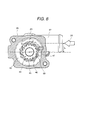
- FIG. 6 shows a cross-sectional view taken along line F-F in FIG. 5 (c).
- FIG. 4 shows a cross-sectional view taken along line E-E in FIG. 5(b).
- FIG. 6 shows a cross-sectional view of the body 39 of the evaporation mixer 10a taken along line F-F in FIG. 5(c).
- the body 39 has an exhaust gas introduction pipe 37, which communicates with a regulator chamber 43 in the body 39.
- the regulator chamber 43 contains a circling nozzle 59.
- the exhaust gas introduction pipe 37 is arranged offset by a distance L from the central axis of the cross section of the regulator chamber 43 of the figure. The exhaust gas 23 is thus introduced, after passing through the exhaust gas introduction pipe 37, at a position offset from the central axis of the cross section of the regulator chamber 43.
- the circling nozzle 59 includes more than one fin 44 with a wing-shaped cross section, which is formed circumferentially therein at regular intervals. Passages formed between each fin 44 have a larger cross section on the exhaust gas 23 inlet side and a smaller cross section on the outlet side.
- the cross section of the regulator chamber 43 is a swirl shape that gradually decreases in size with distance downstream in such a way that the exhaust gas flow 45 through each fin 44 can have a constant flow rate.
- the swirl shape is a structure that can employ a swirl structure in a limited space for a constant external diameter of the regulator chamber 43 and for a gradually smaller cross section perpendicular to the axial flow direction of the urea solution injection.
- a mixing chamber 46 resides inside the cross section of the circling nozzle 59 of the figure. Upstream of the mixing chamber 46, the urea solution injection valve 9 resides.
- the operation of the diesel engine 1 can flow the exhaust gas 22 into the flue 3. This can flow the exhaust gas 23 into the diversion pipe 7 and the exhaust gas introduction pipe 37 and into the evaporation mixer 10a.
- the urea solution spray 29 injected from the urea solution injection valve 9 in the evaporation mixer 10a is supplied into the mixing chamber 46 downstream of the injection holes 47.
- the exhaust gas 23 diverted at the diversion pipe 7 is supplied into the mixing chamber 46 from the exhaust gas introduction pipe 37 through between each fin 44 formed in the circling nozzle 59 at a constant flow rate as the exhaust gas flow 45.
- the exhaust gas flow 45 supplied into the mixing chamber 46 provides a circling flow 62 of the exhaust gas in the mixing chamber 46.
- the combination of the urea solution spray 29 and circling flow 62 can supply the urea solution spray 29 circumferentially and nearly uniformly on the heating surface 50.
- the urea solution spray 29 supplied on the heating surface 50 moves along the circling flow 62 by circling on the heating surface 50 of the sub passage 60 downstream of the mixing chamber 46.
- Restrictions 48 reside on the heating surface 50 of the sub passage 60.
- the step between the internal diameters of the heating surface 50 and restriction 48 can allow a predetermined amount of the urea solution spray (droplets) 29 to dwell on the heating surface 50 to help evaporate the urea solution spray.
- the urea solution spray (droplets) 29 can move downstream in the axial flow direction along the exhaust gas circling flow 62 by circling on the cylindrical heating surface 50 of the sub passage 60.
- the exhaust gas circling flow 62 and urea solution spray (droplets) 29 have velocity components in the axial flow direction and in the circling direction.
- the restrictions 48 on the heating surface 50 of the sub passage 60 can convert the velocity component in the axial flow direction of the urea solution spray (droplets) 20 moving on the heating surface 50 to the velocity component in the circling direction.
- the velocity component in the axial flow direction decreases and the velocity component in the circling direction increases.
- the restrictions 48 can change the cross-section area of the sub passage 60 perpendicular to the axial flow to form the stagnation area where the urea solution spray (droplets) 29 can dwell.
- the restrictions 48 in the sub passage 60 can help evaporate the urea solution spray (droplets) 29 supplied from the urea solution injection valve 9 and prevent the urea solution liquid flow from occurring outside the evaporation mixer 10a.
- the urea solution spray (droplets) 29 can dwell on the heating surface 50 for an extended time to evaporate more urea solution.
- the extended dwell time can cause the evaporation of the same amount of the urea solution with less heating capacity, thereby providing a compact evaporation mixer 10a.
- the denitration catalyst 5 can effectively reduce and remove NOx in the exhaust gas 22 as in the first embodiment.
- FIG. 7 shows the overall configuration of the exhaust gas treatment system of an embodiment according to the present invention.
- FIG. 8 shows an enlarged view of the G section in FIG. 7.
- This embodiment differs from the first embodiment mainly in the configuration of the evaporation mixer 10a, and configuration of the diversion pipe 7 downstream of the urea solution injection valve 9. Other configurations are the same as in the first embodiment, so their description is omitted here.
- This embodiment provides a ring shaped restriction 51 in the diversion pipe 7 downstream of the urea solution injection valve 9.
- the heater 30 resides outside the diversion pipe 7 downstream of the urea solution injection valve 9 as in the first embodiment.
- the thermal insulation member 31 resides outside the heater 30 for improving the thermal insulation to the ambient air.
- the diversion pipe 7 has the diversion pipe outlet 63 that opens in the flue 3 downstream of the diversion control valve 6.
- the diversion pipe outlet 63 has a bell mouth shape that can disperse and supply the mixed fluid 27 into the flue 3.
- the flue 3 downstream of the diversion pipe 63 contains a circling member 52 with a wing 53 for helping mix the fluid in the flue 3 and allowing the urea solution droplets to adhere on the heating surface that is the inner surface of the flue 3 (described below).
- the heater 11 as a heating element resides outside the flue 3 downstream of the vicinity of the wing 53 as in FIG. 2.
- the heater 11 can heat the heating surface 55 that is the wall surface in the flue 3.
- the thermal insulation member 64 resides outside the heater 11 for improving the thermal insulation to the ambient air.
- Ring shaped restrictions 67 reside on the heating surface 55 at a predetermined distance along the axial flow direction of the flue 3.
- the urea solution injection valve 9 injects the urea solution spray 29 into the exhaust gas 23 to help evaporate the urea solution.
- the heater 30 downstream of the urea solution injection valve 9 can further help evaporate the urea solution by its heat.
- the restrictions 51 in the diversion pipe 7 can allow the mixed fluid flow of the exhaust gas 23 and urea solution spray 29 to form stagnation areas upstream and downstream of the restrictions 51 and dwell there. This can supply heat to the mixed fluid more effectively to help evaporate the fluid. This can help hydrolysis to generate a mixed fluid 27 including ammonia decomposed from the urea. The mixed fluid 27 is then emitted from the diversion pipe outlet 63 downstream.
- the diversion pipe outlet 63 has a bell mouth shape that can disperse and supply the mixed fluid 27 upstream of the circling member 52 in the flue 3.
- the wing 52 of the circling member 53 can change the mixed fluid 27 supplied upstream of the circling member 52 to a circling flow 66 downstream of the circling member 52.
- the circling flow 66 can allow relatively heavy things such as the residual urea solution droplets in the mixed fluid 27 to adhere to the heating surface 55 in the flue 3.
- more than one restriction 13 on the heating surface 55 along the axial flow direction of the flue can allow the mixed fluid 27 to form stagnation areas upstream and downstream of the restrictions 13 and dwell there. This can help evaporate and hydrolyze completely the residual urea solution droplets in the mixed fluid 27 into ammonia. In this way, the urea solution spray 29 injected from the urea solution injection valve 9 can be completely hydrolyzed into ammonia.
- the mixed fluid 27 can form on the heating surface 55 in the flue 3 the circling flow 66 that can help mix the fluid 27 with the exhaust gas 24 and supply the fluid 27 uniformly on the denitration catalyst 5.
- the denitration catalyst 5 can thus effectively reduce and remove NOx in the exhaust gas 22.
- a urea decomposition catalyst preferably adheres to the heating surface 55 of the evaporation mixer 10a.
- the urea decomposition catalyst can further improve the urea decomposition rate to improve the denitration efficiency on the denitration catalyst even in a relatively low temperature atmosphere.
- the active ingredient of the urea decomposition catalyst is preferably a metal oxide or metal oxide composite.
- an exhaust gas treatment system in which an exhaust gas is introduced into a denitration catalyst reactor 5 provided in an exhaust gas flue 3, where nitrogen oxide is reduced in the presence of the denitration catalyst, comprising: an exhaust gas diversion passage portion such as a diversion pipe 7 provided in the exhaust gas flue 3; a urea solution injection valve 9 or a liquid reducing agent injection device, which is provided in the exhaust gas diversion passage portion 7 and in which part or all of the exhaust gas 23 is introduced, for injecting a urea solution into the exhaust gas introduced, or for injecting a liquid reducing agent into the exhaust gas introduced, respectively; an ammonia generation portion, which has heating means by heaters 30 and 11, for decomposing particulate droplets of the urea solution or liquid reducing agent, and the urea or liquid reducing agent, to generate ammonia by one or both of heat from the exhaust gas and heat from the heater; a mixing portion such as an evaporation mixer 10 for mixing the generated ammonia with the exhaust gas; and the denitration catalyst
- an exhaust gas treatment system in which an exhaust gas is introduced into a denitration catalyst reactor 5 provided in an exhaust gas flue 3, where nitrogen oxide is reduced in the presence of the denitration catalyst, comprising: a urea solution injection valve 9 for injecting a urea solution into the exhaust gas introduced from the exhaust gas flue 3; an ammonia generation portion, which has heating means by a heater 30, for decomposing particulate droplets of the urea solution and urea to generate ammonia by at least heat of the above-described heater; a mixed gas carrier portion, which has another heating means by a heater 11, for decomposing particulate droplets of a residual urea solution and urea, and for mixing the generated ammonia with the exhaust gas, and for carrying the mixed gas; and the denitration catalyst reactor 5 in which the mixed gas of the heated ammonia and exhaust gas is introduced.
- the exhaust gas diversion passage portion 7 may comprise an exhaust flow control valve 6 which changes a diversion amount of the exhaust gas into the urea solution injection valve 9 depending on output from part or all of an exhaust gas temperature sensor, an exhaust gas flow rate sensor, and a nitrogen oxide sensor.
- the above-described mixing portion may be provided in the exhaust gas diversion passage portion 7.
- the above-described mixing portion may be provided in the exhaust gas flue 3.
- the above-described ammonia generation portion comprises a urea decomposition catalyst reactor.
- a urea solution injection device including the urea solution injection valve 9 may be provided, wherein the above-described urea solution injection device may comprise a urea solution injection amount control device which changes an amount of the injected urea solution depending on output from part or all of an exhaust gas temperature sensor, an exhaust gas flow rate sensor, and a nitrogen oxide sensor.
- a heater temperature control device may be provided which changes an amount of heat generated depending on output from part or all of an exhaust gas temperature sensor, an exhaust gas flow rate sensor, and a nitrogen oxide sensor.
- the above-described heater temperature control device may comprise a heat amount change pattern for changing the amount of heat generated according to a previously stored heat generation pattern depending on an engine operating condition.
- the above-described heat amount change pattern is that a smaller amount of heat is generated for higher temperatures and a greater flow rate of the exhaust gas.
- a circling means mixes the particulate droplets of the urea solution and ammonia with the exhaust gas.
- an exhaust gas treatment system in which an exhaust gas is introduced into a denitration catalyst reactor 5 provided in an exhaust gas flue 3, where nitrogen oxide is reduced in the presence of the denitration catalyst, comprising: a urea solution injection valve 9 for injecting a urea solution into part of the exhaust gas 23 introduced from the exhaust gas flue 3; a first ammonia generation portion, which has a heating means by a heater 30, for decomposing particulate droplets of the urea solution and urea to generate ammonia by at least heat of the heater 30; a second ammonia generation portion, which has another heating means by a heater 11, for decomposing particulate droplets of a residual urea solution and urea to generate ammonia; a mixed gas carrier portion for mixing the generated ammonia with the exhaust gas by a circling means, and for carrying the mixed gas of the heated ammonia and exhaust gas with allowing its temporal dwelling between a plurality of restrictions 13 and 67; and the denitration catalyst reactor 5 in which the above-de
- an exhaust gas diversion means is mounted, and a heating element such as a heater is positively used to help evaporate a liquid reducing agent such as a urea solution for lower temperatures and a smaller amount of the exhaust gas, such as at the startup of the engine.
- the exhaust heat is positively used to help evaporate the urea solution for higher temperatures and a larger amount of the exhaust gas, such as at a high-load engine area.
- the exhaust gas 23 and urea solution spray 29 are circled and mixed and more than one restriction is mounted in a passage downstream of the urea solution injection valve 9 to allow the urea solution spray 29 to dwell and to help evaporate it.
- An exhaust gas treatment system and exhaust gas treatment process are thus provided that can efficiently remove the nitrogen oxide (NOx) in the exhaust gas in the whole operating area from the engine start up area to the full load area.
- An exhaust gas treatment system and exhaust gas treatment process are also provided that can achieve the compact structure and low power consumption.
Landscapes
- Chemical & Material Sciences (AREA)
- Engineering & Computer Science (AREA)
- Chemical Kinetics & Catalysis (AREA)
- Combustion & Propulsion (AREA)
- Health & Medical Sciences (AREA)
- General Engineering & Computer Science (AREA)
- Mechanical Engineering (AREA)
- General Chemical & Material Sciences (AREA)
- Analytical Chemistry (AREA)
- Oil, Petroleum & Natural Gas (AREA)
- Environmental & Geological Engineering (AREA)
- Biomedical Technology (AREA)
- Toxicology (AREA)
- Exhaust Gas After Treatment (AREA)
- Treating Waste Gases (AREA)
- Exhaust Gas Treatment By Means Of Catalyst (AREA)
Abstract
Description
- The present invention relates to an exhaust gas treatment system and treatment process there of, and more particularly, to an exhaust gas treatment system and process which use urea as a reducing agent and can efficiently remove nitrogen oxide in the exhaust gas even in a low temperature region.
- Nitrogen oxide (hereinafter referred to as NOx) included in the exhaust gas emitted from the diesel engines used in vehicles such as a heavy truck and a bus is a material that can cause photochemical smog. Effluent control of NOx that is to be enhanced for these vehicles urgently needs the installation of an exhaust gas denitration system.
- One of the removal (denitration) methods considered is to use nontoxic urea as the reducing agent to make it possible to reduce NOx highly efficiently. For example, an exhaust gas cleaning system is provided that utilizes a urea solution as the reducing agent, and includes a NOx reduction catalyst provided in the exhaust pipe to make it possible to obtain a high rate of NOx reduction even in a relatively low temperature region, and is configured to add the urea solution as the reducing agent upstream of NOx reduction catalyst.
- In this system, a urea decomposition catalyst is provided between two positions in the longitudinal direction of the exhaust pipe, the position where the urea solution is added and the position where NOx reduction catalyst is provided. This pre-step urea decomposing catalyst can decompose the urea solution into ammonia and carbon dioxide.
- The ammonia thus obtained is highly reactive with NOx and enables efficient execution of reduction treatment of NOx to make it possible to reduce and clean NOx in a relatively lower temperature region than for the direct reaction of the urea solution with NOx (see, for example, Japanese Application Patent Laid-open Publication No. 2002-161732 (pp. 2-4, Figure 1)).
- Japanese Application Patent Laid-open Publication No. 2002-89241 describes a denitration system that includes a denitration catalyst in the exhaust gas pipe of the internal combustion engine, and that introduces a reducing agent into the pipe to add the agent in the exhaust gas and then brings the exhaust gas into contact with the denitration catalyst, thereby denitrating the exhaust gas.
- This system comprises a reactor, which can store urea in solid state and zeolite together, a heating means for heating the reactor, and a water vessel for storing water. The water vessel introduces the water into the reactor, while the heating means heats the reactor to hydrolyze the urea into ammonia gas that is added into the exhaust gas as the reducing agent.
- Also known is a disclosure of Japanese Application Patent Laid-open Publication No. 2002-332827.
- A urea SCR system is known as the exhaust gas cleaning system that includes no urea decomposition catalyst of the exhaust gas cleaning system described above (see, for example, Matsuo Odaka, "Challenge for Ultra Low Emission Diesel Engine," Journal of the Japan Society of Mechanical Engineers, 2002.10, Vol. 105, No. 1007, p.23).
- The first conventional technique (Japanese Application Patent Laid-open Publication No. 2002-161732) provides the urea decomposition catalyst between the position where the urea solution is added and the position where the NOx reduction catalyst is provided and adds (injects) directly the urea solution on the urea decomposition catalyst. The urea decomposition catalyst can thus decompose the urea solution into ammonia and carbon dioxide, and the ammonia from decomposition can then react with NOx on the NOx reduction catalyst to denitrate the NOx efficiently.
- It is difficult, however, to disperse and supply directly and uniformly the urea solution onto the urea decomposition catalyst. It may also take a relatively long time for the urea decomposition catalyst to decompose the urea solution. From these, it is preferable to help mix the urea solution with the exhaust gas to evaporate it. The mixture can then be provided onto the urea decomposition catalyst in urea vapor or the like.
- One way for this is to ensure a predetermined distance between the injection nozzle and the urea decomposition catalyst in such a way that the exhaust heat of the exhaust gas can heat and help evaporate the urea solution before the solution reaches the urea decomposition catalyst. The evaporation of the urea-solution spray injected, however, needs a flue length of, for example, about 1.5 m for a urea solution spray with a droplet diameter of about 100 µm, and needs a flue length of about 6.2 m for a droplet diameter of about 200 µm. This may cause a large system that is unsuitable for automobile use.
- The above-described way to obtain an amount of heat from the exhaust heat of the exhaust gas for the evaporation may be effective in view of high exhaust gas temperatures generating a large amount of NOx that needs more urea solution. At the startup of the engine, however, this way can achieve insufficient efficiency of evaporation due to lower temperatures and a smaller amount of the exhaust gas. It is thus difficult to efficiently reduce and clean NOx at lower temperatures such as at the startup.
- The second conventional technique (Japanese Application Patent Laid-open Publication No. 2002-89241) is an exhaust gas treatment system that evaporates the urea solution and uses ammonia from the hydrolysis as the reducing agent for the denitration catalyst reaction. If this exhaust gas treatment system is applied to vehicles with diesel engines such as a heavy truck and bus, the evaporation and hydrolysis of the maximum required amount of the urea solution (50 cc/min, 32.5 wt%, 25°C) needs about 2.4 kW of the minimum required amount of heat. It is difficult to obtain such an amount of power from the automobile battery.
- It is an object of the present invention to provide an exhaust gas treatment system and an exhaust gas treatment process suitable for an automobile use, which can remove NOx, and use as the reducing agent easy-to-handle materials such as urea, and can respond to the whole operating area from an area with low temperatures and a small amount of exhaust gas, such as at the startup, to a full load area with high temperatures and a large amount of exhaust gas, and has a compact structure, good response, and low power consumption,
- The present invention achieves the above-described objects, generally according to the following concepts.
- The urea solution is atomized and the exhaust gas is used as the carrier gas.
- The heater evaporates the urea solution in the operating area with relatively a smaller amount and lower temperatures of the exhaust gas such as at the startup of the diesel engine. Because smaller amount of NOx is generated in this operating area, less urea solution is to be treated and the heater can have the minimum required capacity and power consumption.
- The heat from the exhaust gas is used to make it possible to evaporate a plenty of urea solution, in case of higher temperatures of the exhaust gas and a plenty of NOx generation.
- The urea solution and exhaust gas are circled and more than one restriction is provided in the flue and evaporator passage to effectively exchange heat between the urea solution and exhaust gas and mix the urea solution with exhaust gas in a space-saving manner.
- An exhaust gas diversion means is provided to make it possible to supply the exhaust gas onto the denitration catalyst over the shortest distance to warm up the denitration catalyst in the shortest time, in the operating area with relatively a smaller amount and lower temperatures of the exhaust gas such as at the startup of the diesel engine.
- The present invention can thus be illustrated as follows.
- (1) An exhaust gas treatment system and process in which an exhaust gas is introduced into a denitration catalyst reactor provided in an exhaust gas flue, where nitrogen oxide is reduced and removed in the presence of the denitration catalyst, comprising: an exhaust gas diversion means in the exhaust gas flue; a urea solution injection evaporator including a urea solution injection valve for injecting a urea solution into part or all of the exhaust gas introduced by the above-described diversion means and an evaporation mixer; a heating means by a heater; a mixing means for decomposing particulate droplets of the urea solution and urea by one or both of heat from the exhaust gas and heat from the heater, and for mixing the generated ammonia with the exhaust gas; and a mixed gas introduction portion for introducing the above-described mixed gas into the denitration catalyst reactor, wherein the above-described ammonia is used as the reducing agent for the denitration catalyst reaction. The urea solution injection valve may be replaced with a liquid reducing agent injection device for injecting a liquid reducing agent of the urea solution and hydrocarbon (HC).
- (2) An exhaust gas treatment system and process according to the above-described (1), wherein the above-described exhaust gas diversion means changes the diversion amount into the urea solution injection evaporator depending on output from part or all of an exhaust gas temperature sensor, an exhaust gas flow rate sensor, and a nitrogen oxide sensor.
- (3) An exhaust gas treatment system and process according to the above-described (1) or (2), wherein the above-described urea solution injection device changes the amount of the urea solution injected depending on output from part or all of an exhaust gas temperature sensor, an exhaust gas flow rate sensor, and a nitrogen oxide sensor.
- (4) An exhaust gas treatment system and process according to the above-described (3), wherein the above-described heater changes the amount of heat generated depending on output from part or all of an exhaust gas temperature sensor, an exhaust gas flow rate sensor, and a nitrogen oxide sensor.
- (5) An exhaust gas treatment system and process according to the above-described (3), wherein the above-described heater changes the amount of heat generated according to a previously stored heat generation pattern depending on an engine operating condition.
- (6) An exhaust gas treatment system and process according to the above-described (4), wherein the above-described heater generates a smaller amount of heat for higher temperatures and a greater flow rate of the exhaust gas.
- (7) An exhaust gas treatment system and process according to the above described (1) - (6), wherein the above-described mixing means mixes the particulate droplets of the urea solution and ammonia with the exhaust gas by circling them.
- (8) An exhaust gas treatment system and process according to the above described (1) - (7), wherein a plurality of restrictions are provided in the flue and evaporator passage through which the particulate droplets of the urea solution, ammonia, and exhaust gas pass, for an extended dwell time of the particulate droplets.
- (9) An exhaust gas treatment system and process according to the above-described (7) and (8), wherein a urea decomposition catalyst reactor is provided in the connection between the above-described mixed gas introduction portion and exhaust gas flue.
- (10) An exhaust gas treatment system and process according to the above-described (9), wherein the above-described urea decomposition catalyst uses a metal oxide or metal oxide composite as its active ingredient.
-
-
- Figure 1 shows an engine exhaust gas treatment system of the first embodiment according to the present invention.
- Figure 2 shows an enlarged cross-sectional view of the A section in the engine exhaust gas treatment system shown in Figure 1 according to the present invention.
- Figure 3 shows an engine exhaust gas treatment system of the second embodiment according to the present invention.
- Figure 4 shows a cross-sectional view taken along line E-E of the exhaust gas treatment system shown in Figure 5 (b) according to the present invention, which is also an enlarged view of the B section in Figure 3.
- Figure 5 shows (a) a perspective view, (b) a front view, and (c) a side view of the exhaust gas treatment system shown in Figure 3 according to the present invention.
- Figure 6 shows a cross-sectional view taken along line F-F of the exhaust gas treatment system shown in Figure 5 (c) according to the present invention.
- Figure 7 shows an engine exhaust gas treatment system of the third embodiment according to the present invention.
- Figure 8 shows an enlarged cross-sectional view of the G section in the engine exhaust gas treatment system shown in Figure 7 according to the present invention.
-
- The present invention will be described below with reference to the drawings and embodiments.
- The first embodiment according to the present invention will now be described with reference to FIGS. 1 and 2. FIG. 1 shows the overall configuration of the exhaust gas treatment system of an embodiment according to the present invention. The
diesel engine 1 determines the fuel injection amount and injection timing based on various signals that are input to the ECU (Electric Control Unit) 2. The diesel engine also has a not-shown EGR (exhaust gas recirculation) valve and an intake throttle that is used together with the EGR valve to expand the control region of the EGR rate. - DPF (Diesel Particulate Filter) 4, which is a diesel particulate removal device, resides in the
flue 3 that is an exhaust passage of theexhaust gas 22 emitted from thediesel engine 1. Downstream of the DPF, a denitration catalyst (SCR: Selective Catalytic Reduction: selective reduction type NOx catalyst) 5 (denitration catalyst reactor) resides. Further downstream of the SCR, a not-shown muffler and the like reside. An exhaustflow control valve 6 resides in theflue 3 between theDPF 4 anddenitration catalyst 5. - A
valve drive unit 28 controls the open/close of the exhaustflow control valve 6 using the control signals from theECU 2 based on signals from sensors such as an exhaustgas temperature sensor 15, aNOx sensor 16, and an NH3 sensor, according to the operating condition of thediesel engine 1. Adiversion pipe 7, which is an exhaust gas diversion passage, connects to theflue 3 between theDPF 4 and exhaustflow control valve 6. Thediversion pipe 7 has a ureasolution injection valve 9 for injecting and supplying theurea solution spray 29 into thediversion pipe 7. - A
heater 30 as a heating means resides outside thediversion pipe 7 downstream of the ureasolution injection valve 9. This can make up an ammonia generation portion for generating ammonia by decomposing the particulate droplets of the injected urea solution and urea. The exhaust gas that flows during the ammonia generation will mix with the ammonia. Athermal insulation member 31 resides outside theheater 30 for improving the thermal insulation to the ambient air. - Downstream of the
heater 30, anevaporation mixer 10 resides outside theflue 3 in a ring shape at a predetermined height from theflue 3 with a length in the axial flow direction of theflue 3. Anotherheater 11 resides outside theevaporation mixer 10 which can heat the inner surface (heating surface) of the evaporation mixer depending upon a predetermined operating condition. - A
thermal insulation member 56 resides outside theheater 11 for improving the thermal insulation to the ambient air. This can make up another ammonia generation portion for generating ammonia by decomposing the particulate droplets of residual urea solution and urea. More than onerestriction 13 in a ring shape resides on theheating surface 12 that is the inner surface of theevaporation mixer 10. - The
restrictions 13 can change the cross section area of theevaporation mixer 10 passage along the axial flow direction. Downstream of theevaporation mixer 10, anevaporation mixer outlet 14 resides which communicates with theflue 3 downstream of the exhaustflow control valve 6. - The
flue 3 contains various sensors such as the exhaustgas temperature sensor 15,NOx sensor 16, NH3 sensor 17, and not-shown engine crank angle sensor. These sensors can keep track of the operating conditions of thediesel engine 1 or the like so that theECU 2 can set the optimum opening of the exhaustflow control valve 6 to control the exhaust gas diversion ratio for flows into theflue 3 anddiversion pipe 7. - The
ECU 2 can also control the setting temperature of theheaters solution injection valve 9 or the like. Theurea solution 8 stored in theurea solution tank 17 is supplied through thefilter 18 and pump 19 to the ureasolution injection valve 9. - A
regulator 20 can adjust the urea solution supply pressure to the ureasolution injection valve 9 at a predetermined urea solution supply pressure. Thereturn urea solution 8 from theregulator 20 flows into theurea solution tank 17. Apipe 21 connects the above-describedurea solution tank 17,filter 18, pump 19 andregulator 20. - FIG. 2 shows an enlarged view of the A section in FIG. 1. Referring to FIG. 2, the detailed configuration of the engine exhaust gas treatment system, exhaust gas flow,
spray 29 injected from the ureasolution injection valve 9, andmixed gas flow - The
exhaust gas 22 emitted from thediesel engine 1 passes through theDPF 4. The open/close control of the exhaustflow control valve 6 downstream of theDPF 4 then flows theexhaust gas 22 into thediversion pipe 7 upstream of the exhaustflow control valve 6 via adiversion pipe inlet 54 and into theflue 3 downstream of the exhaustflow control valve 6. This can control the flow ratio of the eachexhaust flow - In the cold state at the startup of the
diesel engine 1, the opening of the exhaustflow control valve 6 is controlled to flowmore exhaust gas 24 into theflue 3. This can activate early the denitration catalyst 5 (FIG. 1) to ensure high denitration efficiency. - The catalyst is thus most preferentially heated to remove efficiently NOx. After the
exhaust gas 24 activates thedenitration catalyst 5, the diversion ratio of the eachexhaust gases - The
diversion pipe 7 has the ureasolution injection valve 9 that makes up a urea solution injection device. The ureasolution injection valve 9 can control the urea solution injection amount depending on the engine operating conditions. When the hightemperatures exhaust gas 23 flows into thediversion pipe 7, the ureasolution injection valve 9 injects theurea solution 8 as thespray 29. - The high
temperature exhaust gas 23 and the droplets in theurea solution spray 29 mix together to exchange heat and help evaporate thespray 29. Theexhaust gas 23 carries theurea solution spray 29 as themixed gas 26 into theevaporation mixer 10 through theevaporation mixer inlet 25. - The
heater 30 resides outside thediversion pipe 7 downstream of the ureasolution injection valve 9 and is set at a predetermined temperature or more. These can help evaporate theurea solution spray 29 and prevent the urea from being precipitated out of theurea solution spray 29 that adheres to the wall surface in thediversion pipe 7. The ammonia carbonate or the like is also prevented from occurring. - The
evaporation mixer 10 has theevaporation mixer inlet 25 that is connected off center thereto by a predetermined distance from the center line of the flue cross section that is perpendicular to the flue axial flow direction of theevaporation mixer 10. Therefore, theexhaust gas 23 andurea solution spray 29 help mix and evaporation through theflue 7, and themixed gas 26 forms a circlingflow 65 in theevaporation mixer 10. - The circling
flow 65 helps further mix themixed gas 26 and allows the relatively heavy urea solution droplets in themixed gas 26 that are not completely evaporated to actively adhere to theheating surface 12 that is the inner surface of theevaporation mixer 10. Restrictions in ring shapes reside with a predetermined height and a distance on theheating surface 12 inside theevaporation mixer 10 in the axial flow direction of the flue. The restrictions can form flow stagnation areas where the urea solution droplets can dwell.] - The
heater 11 resides outside theevaporation mixer 10, the heat of which can help evaporate the urea solution droplet groups that actively adhere to and dwell on theheating surface 12 inside theevaporation mixer 10. Theheating surface 12 is preferably set at about 300°C. The above-described configurations andmixed gas flow 26 can completely evaporate theurea solution spray 29 and highly efficiently hydrolyze theurea solution 8 into ammonia. The ammonia can thus be generated highly quickly. - The
evaporation mixer 10 generates ammonia that is carried and supplied into theflue 3 through theevaporation mixer outlet 14. In this way, theevaporation mixer 10 can also act as a mixed gas carrier portion. More than oneevaporation mixer outlet 14 resides off center from the centerline of theflue 3 cross section that is perpendicular to theflue 3 axial flow direction to allow themixed gas 27 to form a circlingflow 66 in theflue 3. Themixed gas 27 including a plenty of ammonia can thus form a circlingflow 66 in theflue 3. - The circling
flow 66 can help mix theexhaust gas 24 andmixed gas 27 to supply the ammonia in themixed fluid 27 uniformly to thedenitration catalyst 5. High denitration efficiency can thus be achieved to reduce effectively NOx emitted from thediesel engine 1. - The heat from the
heaters exhaust gases heating surface 12 of the evaporation mixer can transfer more heat to the urea solution droplets that dwell on theheating surface 12. This allows a compact evaporation mixer to completely hydrolyze the urea solution into the ammonia. - A urea decomposition catalyst preferably adheres to the
heating surface 12 of theevaporation mixer 10. The urea decomposition catalyst can further improve the urea decomposition rate to improve the denitration efficiency on the denitration catalyst even in an early relatively low temperature atmosphere. The active ingredient of the urea decomposition catalyst is preferably a metal oxide or metal oxide composite. - In the operating area with relatively a smaller amount and lower temperatures of the
exhaust gas 22 such as at the startup of thediesel engine 1, theheaters flow control valve 6 is controlled to obtain the adequate flow of theexhaust gas 23 by adjusting the diversion ratio of theexhaust gas 24 flowing downstream of the exhaustflow control valve 6 and theexhaust gas 23 flowing into thediversion pipe 7. - The exhaust
flow control valve 6 is also controlled to effectively use the exhaust heat from theexhaust gas 23 and to allow the urea solution droplets to adhere to theheating surface 12 of theevaporation mixer 10 to help evaporate the urea solution. Because smaller amount of NOx is generated in the above-described operating area, less urea solution is to be treated and the heaters can need the minimum required capacity and power consumption. - In the operating area with relatively a larger amount and higher temperatures of the
exhaust gas 23, a plenty of NOx occurs and a plenty of urea solution needs to be evaporated. The exhaustflow control valve 6 is thus controlled to allowmore exhaust gas 23 to flow into thediversion pipe 7. This can supply theurea solution spray 29 in a large quantity of the high temperature exhaust gas and help evaporate theurea solution spray 29 without increasing the heat from theheaters - In this embodiment, the urea
solution injection valve 9 is an upstream circling type injection valve that can atomize theurea solution spray 29 by circling theurea solution 8 upstream of the valve seat that is upstream of the injection holes 47 of the ureasolution injection valve 9. But theinjection valve 9 is not limited to this type of valve and may be any injection valve with a structure that can help atomize theurea solution 8. Theinjection valve 9 may thus be any injection valve of excellent evaporation performance that can help atomize theurea solution 8 injected from the injection valve to improve the evaporation performance of theurea solution 8. - With the above-described configurations and exhaust gas flows and the like, the diversion control of the flow ratio of the
exhaust gases flow control valve 6, theurea solution spray 29 injected from the ureasolution injection valve 9 into the hightemperature exhaust gas 23 flowing through thediversion pipe 7, and the stagnation area formed in theevaporation mixer 10 by the circlingflow 65 andrestrictions 13 can circle and mix the mixed gas 26 (including theexhaust gas 23, urea vapor, and water vapor) and ensure the dwell time and help evaporate the urea solution and facilitate the hydrolysis, in order to make it possible to generate the ammonia (NH3) and carbon dioxide (CO2). - The mix of the ammonia and exhaust gas is also facilitated. The
mixed fluid 27 including ammonia and carbon dioxide is emitted from theevaporation mixer outlet 14. Themixed gas 27 is emitted into theflue 3 as the circlingflow 6 to help mix with theexhaust gas 24 before being supplied onto thedenitration catalyst 5. The ammonia can thus be uniformly supplied onto thedenitration catalyst 5. - Consequently, the
urea solution 8 injected as the reducing agent can be hydrolyzed efficiently and the ammonia generated can be dispersed uniformly (without any drift and uniformized) into theexhaust gas 24 to effectively reduce and remove NOx in theexhaust gas 22 on thedenitration catalyst 5. - In the above embodiment, the
diversion pipe 7 resides outside theflue 3 independently or integrally. The diversion pipe (diversion passage) may also reside inside theflue 3. This can provide a more compact structure. - The second embodiment according to the present invention will now be described with reference to FIGS. 3 to 6.
- FIG. 3 shows the overall configuration of the exhaust gas treatment system of an embodiment according to the present invention. This embodiment differs from the above described first embodiment mainly in the mounting position at which the
diversion pipe inlet 54, configuration of theevaporation mixer 10a, and configuration of themixed gas outlet 14. - This embodiment does not provide the exhaust
flow control valve 6 that is provided in the first embodiment. The diversion pipe inlet mounting structure anddiversion pipe 7 can thus make up the exhaust gas diversion means. Other configurations are the same as in the first embodiment, so their description is omitted here. - In this embodiment, the
diversion pipe inlet 54 opens in a part of theflue 3 in countercurrent with the flow direction of theexhaust gas 22 to divert theexhaust gas 22 from thediesel engine 1 into theflue 3 anddiversion pipe 7. This can split theexhaust gas 22 into theexhaust gas 23 flowing into thediversion pipe 7 and theexhaust gas 24 flowing into theflue 3 downstream of thediversion pipe inlet 54. - FIG. 4 shows an enlarged view of the B section in FIG. 3. In FIGS. 3 and 4, the
flue 3 anddiversion pipe 7 communicate with each other through thediversion pipe inlet 54, and theevaporation mixer 10a communicates with thediversion pipe 7. The ureasolution injection valve 9,heater 49 as a heating element, and more than one ring shapedrestriction 48 on theheating surface 50 reside on theevaporation mixer 10a. - A
urea decomposition catalyst 32 in a honeycomb shape resides downstream of theevaporation mixer 10a. Theurea decomposition catalyst 32 is not limited to the honeycomb shape, and apart from the honeycomb shape, may be a plate-like parallel flow type, and a granular type. Theheater 33 also resides outside the passage that contains theurea decomposition catalyst 32. Theheater 33 can keep the temperature of the passage above a predetermined value and can early warm up theurea decomposition catalyst 32 to early activate it. - The
thermal insulation member 34 resides outside theheater 33 for thermal insulation. These can prevent the urea from being precipitated out of theurea solution spray 29 that adheres to the passage wall surface downstream of theevaporation mixer 10a. The ammonia carbonate or the like is also prevented from occurring. - Downstream of the
urea decomposition catalyst 32, themixed gas outlet 58 resides in theflue 3. The above-described configurations can provide communication from thediversion pipe inlet 54 through theevaporation mixer 10a,urea decomposition catalyst 32, andmixed gas outlet 58 into theflue 3. Themixed gas outlet 58 has a bell mouth shape that can disperse and supply themixed fluid 27 into theflue 3. - The
heater body 42 contains asub passage 60. Aheater 49 such as a sheathed heater resides outside thesub passage 60. The present embodiment uses the sheathed heater for theheater 49, but theheater 49 is not limited thereto. Other heaters such as a plate-like PTC (Positive Temperature Coefficient Thermistor) heater may be used. The PTC heater has upper and lower flat surfaces as electrodes. The upper and lower electrodes through which current passes can heat up. - The PTC is a ceramic heater that at temperatures greater than or equal to a predetermined value can rapidly increase its resistance to decrease the current through it and thus keep the constant temperature.
- More than one
restriction 48 is press fitted and fastened into thesub passage 60 at a predetermined distance along the passage axial flow direction. - The
body 39 has the ureasolution injection valve 9 that is coaxial with theheater body 42. Theurea solution pipe 36 and ureasolution pipe holder 61 fasten the ureasolution injection valve 9 onto thebody 39. The injection holes 47 of the ureasolution injection valve 9 reside in the mixingchamber 46. Theurea solution spray 29 injected from the ureasolution injection valve 9 is thus supplied into the mixingchamber 46 and also into thesub passage 60 downstream thereof. - The
exhaust gas 23 flows into thediversion pipe 7 through thediversion pipe inlet 54 and then flows into theevaporation mixer 10a downstream of thediversion pipe 7. The exhaust heat from theexhaust gas 23 that flows into theevaporation mixer 10a and the heat from theheater 49 can evaporate theurea solution spray 29 injected from the ureasolution injection valve 9 into the urea vapor and water vapor and then hydrolyze the urea vapor into ammonia. Themixed gas 27a of theexhaust gas 23 and ammonia can thus be generated. - Urea not decomposed into ammonia in the
evaporation mixer 10a is completely hydrolyzed into ammonia on theurea decomposition catalyst 32 downstream of theevaporation mixer 10a. Theevaporation mixer outlet 58 can thus supply into theflue 3 the ammonia from theurea spray 29 completely hydrolyzed. Themixed fluid 27 supplied intoflue 3 can help mix with theexhaust gas 24 and be dispersed and supplied uniformly onto thedenitration catalyst 5 and effectively reduce and remove NOx in the exhaust gas on thedenitration catalyst 5. NOx removed is then exhausted. - FIG. 5(a) shows a perspective view of the B section in FIG. 3. FIGS. 5(b) and (c) show perspective views as viewed in the direction of the arrows C and D in FIG. 5 (a). FIG. 6 shows a cross-sectional view taken along line F-F in FIG. 5 (c). FIG. 4 shows a cross-sectional view taken along line E-E in FIG. 5(b).
- FIG. 6 shows a cross-sectional view of the
body 39 of theevaporation mixer 10a taken along line F-F in FIG. 5(c). Thebody 39 has an exhaustgas introduction pipe 37, which communicates with aregulator chamber 43 in thebody 39. Theregulator chamber 43 contains a circlingnozzle 59. The exhaustgas introduction pipe 37 is arranged offset by a distance L from the central axis of the cross section of theregulator chamber 43 of the figure. Theexhaust gas 23 is thus introduced, after passing through the exhaustgas introduction pipe 37, at a position offset from the central axis of the cross section of theregulator chamber 43. - The circling
nozzle 59 includes more than onefin 44 with a wing-shaped cross section, which is formed circumferentially therein at regular intervals. Passages formed between eachfin 44 have a larger cross section on theexhaust gas 23 inlet side and a smaller cross section on the outlet side. The cross section of theregulator chamber 43 is a swirl shape that gradually decreases in size with distance downstream in such a way that theexhaust gas flow 45 through eachfin 44 can have a constant flow rate. - The swirl shape is a structure that can employ a swirl structure in a limited space for a constant external diameter of the
regulator chamber 43 and for a gradually smaller cross section perpendicular to the axial flow direction of the urea solution injection. - A mixing
chamber 46 resides inside the cross section of the circlingnozzle 59 of the figure. Upstream of the mixingchamber 46, the ureasolution injection valve 9 resides. - A description is now given of the fluid flow emitted from the
internal combustion engine 1 with the above-describedevaporation mixer 10a. In this embodiment, the operation of thediesel engine 1 can flow theexhaust gas 22 into theflue 3. This can flow theexhaust gas 23 into thediversion pipe 7 and the exhaustgas introduction pipe 37 and into theevaporation mixer 10a. Theurea solution spray 29 injected from the ureasolution injection valve 9 in theevaporation mixer 10a is supplied into the mixingchamber 46 downstream of the injection holes 47. - The
exhaust gas 23 diverted at thediversion pipe 7 is supplied into the mixingchamber 46 from the exhaustgas introduction pipe 37 through between eachfin 44 formed in the circlingnozzle 59 at a constant flow rate as theexhaust gas flow 45. Theexhaust gas flow 45 supplied into the mixingchamber 46 provides a circlingflow 62 of the exhaust gas in the mixingchamber 46. The combination of theurea solution spray 29 and circlingflow 62 can supply theurea solution spray 29 circumferentially and nearly uniformly on theheating surface 50. - The
urea solution spray 29 supplied on theheating surface 50, as the urea solution spray (droplets) on theheating surface 50, moves along the circlingflow 62 by circling on theheating surface 50 of thesub passage 60 downstream of the mixingchamber 46.Restrictions 48 reside on theheating surface 50 of thesub passage 60. The step between the internal diameters of theheating surface 50 andrestriction 48 can allow a predetermined amount of the urea solution spray (droplets) 29 to dwell on theheating surface 50 to help evaporate the urea solution spray. - In the
evaporation mixer 10a with therestrictions 48, the urea solution spray (droplets) 29 can move downstream in the axial flow direction along the exhaustgas circling flow 62 by circling on thecylindrical heating surface 50 of thesub passage 60. The exhaustgas circling flow 62 and urea solution spray (droplets) 29 have velocity components in the axial flow direction and in the circling direction. - The
restrictions 48 on theheating surface 50 of thesub passage 60 can convert the velocity component in the axial flow direction of the urea solution spray (droplets) 20 moving on theheating surface 50 to the velocity component in the circling direction. In other words, the velocity component in the axial flow direction decreases and the velocity component in the circling direction increases. - This can increase the number of circling of the exhaust
gas circling flow 62 and urea solution spray (droplets) flowing along theflow 62 and can extremely increase the dwell time of the urea solution spray (droplets) on theheating surface 50. Therestrictions 48 can change the cross-section area of thesub passage 60 perpendicular to the axial flow to form the stagnation area where the urea solution spray (droplets) 29 can dwell. - The effect of the
restrictions 48 of this embodiment will now be described. Therestrictions 48 in thesub passage 60 can help evaporate the urea solution spray (droplets) 29 supplied from the ureasolution injection valve 9 and prevent the urea solution liquid flow from occurring outside theevaporation mixer 10a. - In other words, the urea solution spray (droplets) 29 can dwell on the
heating surface 50 for an extended time to evaporate more urea solution. Specifically, the extended dwell time can cause the evaporation of the same amount of the urea solution with less heating capacity, thereby providing acompact evaporation mixer 10a. - In addition, the
denitration catalyst 5 can effectively reduce and remove NOx in theexhaust gas 22 as in the first embodiment. - The third embodiment according to the present invention will now be described with reference to FIGS. 7 and 8. FIG. 7 shows the overall configuration of the exhaust gas treatment system of an embodiment according to the present invention. FIG. 8 shows an enlarged view of the G section in FIG. 7.
- This embodiment differs from the first embodiment mainly in the configuration of the
evaporation mixer 10a, and configuration of thediversion pipe 7 downstream of the ureasolution injection valve 9. Other configurations are the same as in the first embodiment, so their description is omitted here. - This embodiment provides a ring shaped
restriction 51 in thediversion pipe 7 downstream of the ureasolution injection valve 9. Theheater 30 resides outside thediversion pipe 7 downstream of the ureasolution injection valve 9 as in the first embodiment. Thethermal insulation member 31 resides outside theheater 30 for improving the thermal insulation to the ambient air. - The
diversion pipe 7 has thediversion pipe outlet 63 that opens in theflue 3 downstream of thediversion control valve 6. Thediversion pipe outlet 63 has a bell mouth shape that can disperse and supply themixed fluid 27 into theflue 3. Theflue 3 downstream of thediversion pipe 63 contains a circlingmember 52 with awing 53 for helping mix the fluid in theflue 3 and allowing the urea solution droplets to adhere on the heating surface that is the inner surface of the flue 3 (described below). - In addition, the
heater 11 as a heating element resides outside theflue 3 downstream of the vicinity of thewing 53 as in FIG. 2. Theheater 11 can heat theheating surface 55 that is the wall surface in theflue 3. Thethermal insulation member 64 resides outside theheater 11 for improving the thermal insulation to the ambient air. Ring shapedrestrictions 67 reside on theheating surface 55 at a predetermined distance along the axial flow direction of theflue 3. - A description is now given of the fluid flow emitted from the
internal combustion engine 1 of the above-described configuration. The hightemperature exhaust gas 23 flows into thediversion pipe 7. The ureasolution injection valve 9 injects theurea solution spray 29 into theexhaust gas 23 to help evaporate the urea solution. Theheater 30 downstream of the ureasolution injection valve 9 can further help evaporate the urea solution by its heat. - The
restrictions 51 in thediversion pipe 7 can allow the mixed fluid flow of theexhaust gas 23 andurea solution spray 29 to form stagnation areas upstream and downstream of therestrictions 51 and dwell there. This can supply heat to the mixed fluid more effectively to help evaporate the fluid. This can help hydrolysis to generate amixed fluid 27 including ammonia decomposed from the urea. Themixed fluid 27 is then emitted from thediversion pipe outlet 63 downstream. - The
diversion pipe outlet 63 has a bell mouth shape that can disperse and supply themixed fluid 27 upstream of the circlingmember 52 in theflue 3. Thewing 52 of the circlingmember 53 can change themixed fluid 27 supplied upstream of the circlingmember 52 to a circlingflow 66 downstream of the circlingmember 52. The circlingflow 66 can allow relatively heavy things such as the residual urea solution droplets in themixed fluid 27 to adhere to theheating surface 55 in theflue 3. - In addition, more than one
restriction 13 on theheating surface 55 along the axial flow direction of the flue can allow themixed fluid 27 to form stagnation areas upstream and downstream of therestrictions 13 and dwell there. This can help evaporate and hydrolyze completely the residual urea solution droplets in themixed fluid 27 into ammonia. In this way, theurea solution spray 29 injected from the ureasolution injection valve 9 can be completely hydrolyzed into ammonia. - Further, the
mixed fluid 27 can form on theheating surface 55 in theflue 3 the circlingflow 66 that can help mix the fluid 27 with theexhaust gas 24 and supply the fluid 27 uniformly on thedenitration catalyst 5. Thedenitration catalyst 5 can thus effectively reduce and remove NOx in theexhaust gas 22. - A urea decomposition catalyst preferably adheres to the
heating surface 55 of theevaporation mixer 10a. The urea decomposition catalyst can further improve the urea decomposition rate to improve the denitration efficiency on the denitration catalyst even in a relatively low temperature atmosphere. The active ingredient of the urea decomposition catalyst is preferably a metal oxide or metal oxide composite. - As described above, an exhaust gas treatment system is provided in which an exhaust gas is introduced into a
denitration catalyst reactor 5 provided in anexhaust gas flue 3, where nitrogen oxide is reduced in the presence of the denitration catalyst, comprising: an exhaust gas diversion passage portion such as adiversion pipe 7 provided in theexhaust gas flue 3; a ureasolution injection valve 9 or a liquid reducing agent injection device, which is provided in the exhaust gasdiversion passage portion 7 and in which part or all of theexhaust gas 23 is introduced, for injecting a urea solution into the exhaust gas introduced, or for injecting a liquid reducing agent into the exhaust gas introduced, respectively; an ammonia generation portion, which has heating means byheaters evaporation mixer 10 for mixing the generated ammonia with the exhaust gas; and thedenitration catalyst reactor 5 in which a mixed gas of the ammonia and exhaust gas is introduced. - In addition, an exhaust gas treatment system is provided in which an exhaust gas is introduced into a
denitration catalyst reactor 5 provided in anexhaust gas flue 3, where nitrogen oxide is reduced in the presence of the denitration catalyst, comprising: a ureasolution injection valve 9 for injecting a urea solution into the exhaust gas introduced from theexhaust gas flue 3; an ammonia generation portion, which has heating means by aheater 30, for decomposing particulate droplets of the urea solution and urea to generate ammonia by at least heat of the above-described heater; a mixed gas carrier portion, which has another heating means by aheater 11, for decomposing particulate droplets of a residual urea solution and urea, and for mixing the generated ammonia with the exhaust gas, and for carrying the mixed gas; and thedenitration catalyst reactor 5 in which the mixed gas of the heated ammonia and exhaust gas is introduced. - The exhaust gas
diversion passage portion 7 may comprise an exhaustflow control valve 6 which changes a diversion amount of the exhaust gas into the ureasolution injection valve 9 depending on output from part or all of an exhaust gas temperature sensor, an exhaust gas flow rate sensor, and a nitrogen oxide sensor. - The above-described mixing portion may be provided in the exhaust gas
diversion passage portion 7. - The above-described mixing portion may be provided in the
exhaust gas flue 3. - The above-described ammonia generation portion comprises a urea decomposition catalyst reactor.
- A urea solution injection device including the urea
solution injection valve 9 may be provided, wherein the above-described urea solution injection device may comprise a urea solution injection amount control device which changes an amount of the injected urea solution depending on output from part or all of an exhaust gas temperature sensor, an exhaust gas flow rate sensor, and a nitrogen oxide sensor. - A heater temperature control device may be provided which changes an amount of heat generated depending on output from part or all of an exhaust gas temperature sensor, an exhaust gas flow rate sensor, and a nitrogen oxide sensor.
- The above-described heater temperature control device may comprise a heat amount change pattern for changing the amount of heat generated according to a previously stored heat generation pattern depending on an engine operating condition.
- The above-described heat amount change pattern is that a smaller amount of heat is generated for higher temperatures and a greater flow rate of the exhaust gas.
- For example, a circling means mixes the particulate droplets of the urea solution and ammonia with the exhaust gas.
- Further, an exhaust gas treatment system is provided in which an exhaust gas is introduced into a
denitration catalyst reactor 5 provided in anexhaust gas flue 3, where nitrogen oxide is reduced in the presence of the denitration catalyst, comprising: a ureasolution injection valve 9 for injecting a urea solution into part of theexhaust gas 23 introduced from theexhaust gas flue 3; a first ammonia generation portion, which has a heating means by aheater 30, for decomposing particulate droplets of the urea solution and urea to generate ammonia by at least heat of theheater 30; a second ammonia generation portion, which has another heating means by aheater 11, for decomposing particulate droplets of a residual urea solution and urea to generate ammonia; a mixed gas carrier portion for mixing the generated ammonia with the exhaust gas by a circling means, and for carrying the mixed gas of the heated ammonia and exhaust gas with allowing its temporal dwelling between a plurality ofrestrictions denitration catalyst reactor 5 in which the above-described mixed gas is introduced. - Of course, the different components of the embodiments 1-3 of the exhaust gas systems described above may be combined in different ways in order to fit with particular demands of a respective desired application, according to the knowledge of an expert skilled in the art.
- According to the present invention, an exhaust gas diversion means is mounted, and a heating element such as a heater is positively used to help evaporate a liquid reducing agent such as a urea solution for lower temperatures and a smaller amount of the exhaust gas, such as at the startup of the engine. The exhaust heat is positively used to help evaporate the urea solution for higher temperatures and a larger amount of the exhaust gas, such as at a high-load engine area.
- The
exhaust gas 23 andurea solution spray 29 are circled and mixed and more than one restriction is mounted in a passage downstream of the ureasolution injection valve 9 to allow theurea solution spray 29 to dwell and to help evaporate it. - An exhaust gas treatment system and exhaust gas treatment process are thus provided that can efficiently remove the nitrogen oxide (NOx) in the exhaust gas in the whole operating area from the engine start up area to the full load area. An exhaust gas treatment system and exhaust gas treatment process are also provided that can achieve the compact structure and low power consumption.
Claims (13)
- An exhaust gas treatment system in which an exhaust gas is introduced into a denitration catalyst reactor (5) provided in an exhaust gas flue (3), where nitrogen oxide is reduced in presence of the denitration catalyst (5), comprising:an exhaust gas diversion passage (7) portion provided in the exhaust gas flue (3);a urea solution injection valve (9), which is provided in said exhaust gas diversion passage portion and in which a part or all of the exhaust gas (22, 23, 24) is introduced, for injecting a urea solution into the introduced exhaust gas (22, 23, 24);an ammonia generation portion, which has heating means by a heater (30, 11), for decomposing particulate droplets of the urea solution and urea to generate ammonia by one or both of heat from the exhaust gas (22, 23, 24) and heat from the heater (30);a mixing portion (10) for mixing the generated ammonia with the exhaust gas (22, 23, 24); andsaid denitration catalyst reactor (5) in which a mixed gas (26, 27) of the ammonia and exhaust gas (22, 23, 24) is introduced.
- An exhaust gas treatment system in which an exhaust gas (22, 23, 24) is introduced into a denitration catalyst reactor (5) provided in an exhaust gas flue (3), where nitrogen oxide is reduced in a presence of the denitration catalyst (5), comprising:a urea solution injection valve (9) for injecting a urea solution (8) into part of the exhaust gas (22, 23, 24) introduced from the exhaust gas flue (3);an ammonia generation portion, which has heating means by a heater (30, 11), for decomposing particulate droplets of the urea solution and urea to generate ammonia by at least heat of said heater (30);a mixed gas carrier portion (10), which has another heating means by a heater, for decomposing particulate droplets of a residual urea solution and urea, and for mixing the generated ammonia with the exhaust gas (22, 23, 24), and for carrying a mixed gas (26, 27) andsaid denitration catalyst reactor (5) in which the mixed gas of the heated ammonia and exhaust gas (22, 23, 24) is introduced.
- Exhaust gas treatment system according to claim 1, characterized in that said exhaust gas diversion passage (7) portion comprises an exhaust flow control valve (6) which changes a diversion amount of the exhaust gas (22, 23, 24) into the urea solution injection valve (9) depending on output from part or all of an exhaust gas temperature sensor (15), an exhaust gas flow rate sensor, and a nitrogen oxide sensor (16).
- Exhaust gas treatment system according to claim 1 or 3, characterized in that said mixing portion is provided in said exhaust gas diversion passage (7) portion.
- Exhaust gas treatment system according to claim 1 or 3, characterized in that said mixing portion is provided in said exhaust gas flue (3).
- Exhaust gas treatment system according to any of the preceding claims, characterized in that said ammonia generation portion comprises a urea decomposition catalyst reactor.
- Exhaust gas treatment system according to any of the preceding claims, characterized by further comprising a urea solution injection device including said urea solution injection valve (9), wherein said urea solution injection device comprises a urea solution injection amount control device which changes an amount of the injected urea solution depending on output from part or all of an exhaust gas temperature sensor, an exhaust gas flow rate sensor, and a nitrogen oxide sensor.
- Exhaust gas treatment system according to any of the preceding claims, characterized by comprising a heater temperature control device which changes an amount of heat generated depending on output from part or all of an exhaust gas temperature sensor (15), an exhaust gas flow rate sensor, and a nitrogen oxide sensor (16).
- Exhaust gas treatment system according to claim 8, characterized in that said heater temperature control device comprises a heat amount change pattern for changing the amount of heat generated according to a previously stored heat generation pattern depending on an engine operating condition.
- Exhaust gas treatment system according to claim 9, characterized in that said heat amount change pattern is that a smaller amount of heat is generated for higher temperatures and a greater flow rate of the exhaust gas (22, 23, 24).
- Exhaust gas treatment system according to any of the preceding claims, characterized in that circling means mixes the particulate droplets of the urea solution and ammonia with the exhaust gas.
- An exhaust gas treatment system in which an exhaust gas is introduced into a denitration catalyst reactor (5) provided in an exhaust gas flue, where nitrogen oxide is reduced in a presence of the denitration catalyst, comprising:a urea solution injection valve (9) for injecting a urea solution into part of the exhaust gas (22, 23) introduced from the exhaust gas flue (3);a first ammonia generation portion, which has heating means by a heater (30), for decomposing particulate droplets of the urea solution and urea to generate ammonia by at least heat of said heater (30);a second ammonia generation portion, which has another heating means by a heater (11), for decomposing particulate droplets of a residual urea solution and urea to generate ammonia;a mixed gas carrier portion (10) for mixing the generated ammonia with the exhaust gas (22, 23) by circling means, and for carrying a mixed gas of the heated ammonia and exhaust gas (22, 23) with allowing its temporal dwelling between a plurality of restrictions; and
said denitration catalyst reactor (5) in which said mixed gas is introduced. - An exhaust gas treatment process in which an exhaust gas is introduced into a denitration catalyst reactor (5) provided in an exhaust gas flue, where nitrogen oxide is reduced in a presence of the denitration catalyst, comprising the steps of:introducing a part or all of the exhaust gas (22, 23, 24) from an exhaust gas diversion passage portion provided in the exhaust gas flue (3), and injecting a liquid reducing agent into the introduced exhaust gas from a liquid reducing agent injection device;having heating means by a heater (11, 30) and decomposing particulate droplets of the liquid reducing agent and the liquid reducing agent to generate ammonia by one or both of heat from the exhaust gas (22, 23, 24) and heat from the heater (11, 30);mixing the generated ammonia with the exhaust gas; andintroducing a mixed gas of the ammonia and exhaust gas (22, 23, 24) into said denitration catalyst reactor (5).
Applications Claiming Priority (2)
| Application Number | Priority Date | Filing Date | Title |
|---|---|---|---|
| JP2003150775 | 2003-05-28 | ||
| JP2003150775A JP4262522B2 (en) | 2003-05-28 | 2003-05-28 | Exhaust gas treatment device for engine and exhaust gas treatment method |
Publications (2)
| Publication Number | Publication Date |
|---|---|
| EP1481719A2 true EP1481719A2 (en) | 2004-12-01 |
| EP1481719A3 EP1481719A3 (en) | 2005-04-13 |
Family
ID=33128246
Family Applications (1)
| Application Number | Title | Priority Date | Filing Date |
|---|---|---|---|
| EP04012440A Withdrawn EP1481719A3 (en) | 2003-05-28 | 2004-05-26 | Engine exhaust gas treatment system and exhaust gas treatment process |
Country Status (3)
| Country | Link |
|---|---|
| US (1) | US7509799B2 (en) |
| EP (1) | EP1481719A3 (en) |
| JP (1) | JP4262522B2 (en) |
Cited By (49)
| Publication number | Priority date | Publication date | Assignee | Title |
|---|---|---|---|---|
| WO2006014129A1 (en) * | 2004-08-06 | 2006-02-09 | Scania Cv Ab (Publ) | Arrangement for supplying a medium into an exhaust gas conduit in an internal combustion engine |
| EP1698768A1 (en) * | 2005-03-02 | 2006-09-06 | Hydraulik-Ring Gmbh | Injection device for the treatment of exhaust fumes motor vehicles |
| EP1715151A1 (en) * | 2005-04-18 | 2006-10-25 | DBK David + Baader GmbH | Heating device and thermal reactor for heating and vaporizing urea |
| WO2007131787A1 (en) * | 2006-05-16 | 2007-11-22 | Emitec Gesellschaft Für Emissionstechnologie Mbh | Method and device for providing a gaseous mixture |
| WO2008020207A1 (en) * | 2006-08-15 | 2008-02-21 | Imi Vision Limited | Exhaust gas treatment |
| WO2008020194A1 (en) * | 2006-08-15 | 2008-02-21 | Imi Vision Limited | Exhaust gas treatment |
| EP1944479A1 (en) | 2007-01-09 | 2008-07-16 | Pierburg GmbH | Thermolysis reactor |
| EP1956206A3 (en) * | 2007-02-09 | 2008-10-08 | Sulzer Chemtech AG | Exhaust gas cleaning system |
| WO2008135535A1 (en) * | 2007-05-08 | 2008-11-13 | Emitec Gesellschaft Für Emissionstechnologie Mbh | Method for providing ammonia for the selective catalytic reduction of nitrogen oxides, and corresponding device |
| FR2921438A1 (en) * | 2007-09-25 | 2009-03-27 | Renault Sas | Fuel vaporizing device for e.g. particle filter, of heat engine of motor vehicle, has vaporizing chamber formed by bell connected and welded on exhaust manifold, where wall of chamber is joined with wall of exhaust manifold |
| FR2921967A1 (en) * | 2007-10-03 | 2009-04-10 | Renault Sas | Reactive fluid e.g. fuel, and exhaust gas mixing device for internal combustion engine of motor vehicle, has controller sending positioning control signal to actuator by communication link and injection control signal to injector |
| WO2009049714A1 (en) | 2007-10-09 | 2009-04-23 | Audi Ag | Device for post-treatment of exhaust gases of a lean-burning internal combustion engine |
| WO2009098096A1 (en) * | 2008-02-08 | 2009-08-13 | Robert Bosch Gmbh | Metering device for pollution reduction in exhaust gases |
| WO2009098484A1 (en) * | 2008-02-06 | 2009-08-13 | Norgren Limited | Urea-hydrolysis and injection system for exhaust gas treatment |
| EP2095866A1 (en) * | 2008-02-25 | 2009-09-02 | JGC Catalysts and Chemicals Ltd. | Exhaust gas treatment apparatus |
| EP2075051A3 (en) * | 2007-12-14 | 2009-09-30 | Hyundai Motor Company | Apparatus for reducing nitrogen oxide in exhaust pipe |
| EP2166207A1 (en) * | 2008-09-23 | 2010-03-24 | MAN Nutzfahrzeuge AG | Device and method for cleaning an exhaust gas flow of an internal combustion engine, in particular an internal combustion engine which is capable to operate under lean conditions |
| EP2101049A3 (en) * | 2008-02-19 | 2010-04-21 | MAN Nutzfahrzeuge Aktiengesellschaft | Compact exhaust gas after treatment system |
| RU2426892C2 (en) * | 2008-08-12 | 2011-08-20 | Ман Трак Унд Бас Аг | Method and device for reconditioning of solid filter located in exhaust channel of internal combustion engine |
| CN102171423A (en) * | 2008-10-16 | 2011-08-31 | 康明斯过滤Ip公司 | Separable decomposition reactor with integral mixer |
| US8071037B2 (en) * | 2008-06-25 | 2011-12-06 | Cummins Filtration Ip, Inc. | Catalytic devices for converting urea to ammonia |
| US8155509B2 (en) * | 2006-05-16 | 2012-04-10 | Emitec Gesellschaft Fuer Emissionstechnologie Mbh | Method and device for providing a gaseous substance mixture |
| CN102658022A (en) * | 2012-05-29 | 2012-09-12 | 福建龙净环保股份有限公司 | SNCR (Selective non-catalytic reaction) denitration system |
| DE102011106233A1 (en) * | 2011-07-01 | 2013-01-03 | Alzchem Ag | Continuous production of ammonia from a solution of an ammonia precursor substance by an ammonia gas generator comprising a catalyst unit, useful to reduce nitrogen oxides in exhaust gases from e.g. industrial plants and gas engines |
| RU2490482C2 (en) * | 2008-08-12 | 2013-08-20 | Ман Трак Унд Бас Аг | Method and device for renovation of solid particle filter located in outlet path of internal combustion engine |
| WO2013004629A3 (en) * | 2011-07-01 | 2013-10-03 | Alzchem Ag | Ammonia gas generator and method for producing ammonia in order to reduce nitrogen oxides in exhaust gases |
| EP2662547A1 (en) * | 2012-05-07 | 2013-11-13 | Electro-Motive Diesel, Inc. | Exhaust system having a pre-heater |
| CN104021273A (en) * | 2014-05-08 | 2014-09-03 | 广东电网公司电力科学研究院 | Method for evaluating influences of denitration system on coal consumption of coal-fired unit |
| EP2687695A4 (en) * | 2011-03-18 | 2015-01-21 | Hino Motors Ltd | UREA SOLUTION REFORMER AND EXHAUST GAS PURIFIER USING THE SAME |
| WO2015071234A1 (en) * | 2013-11-15 | 2015-05-21 | Robert Bosch Gmbh | Device for mixing a liquid medium with a gas stream |
| CN104806328A (en) * | 2009-06-18 | 2015-07-29 | 康明斯知识产权公司 | Apparatus, System, and Method for Reductant Line Heating Control |
| FR3028286A1 (en) * | 2014-11-12 | 2016-05-13 | Peugeot Citroen Automobiles Sa | DEVICE FOR TREATING EXHAUST GASES OF A MOTOR VEHICLE |
| EP2628913A4 (en) * | 2010-10-14 | 2016-07-20 | Mitsubishi Heavy Ind Ltd | MARINE EXHAUST GAS DENITTING DEVICE |
| CN106495184A (en) * | 2016-12-28 | 2017-03-15 | 宁波立达智能控制技术有限公司 | Solid-state ammonium SCR system ammonia generating means |
| CN107327332A (en) * | 2017-06-27 | 2017-11-07 | 中国第汽车股份有限公司 | SSCR systems based on solid ammonia storage material |
| DE102016119306A1 (en) * | 2016-10-11 | 2018-04-12 | Witzenmann Gmbh | Device for mixing fluid streams |
| EP3321484A1 (en) * | 2016-11-14 | 2018-05-16 | Eberspächer Exhaust Technology GmbH & Co. KG | Reaction agent dispensing assembly |
| WO2018202503A1 (en) * | 2017-05-03 | 2018-11-08 | Continental Automotive Gmbh | Exhaust gas system with evaporation element |
| DE102018105514A1 (en) * | 2018-03-09 | 2019-09-12 | Oberland Mangold Gmbh | Method and device for reducing the nitrogen oxides in the exhaust gas of an internal combustion engine |
| US10458301B2 (en) | 2016-11-14 | 2019-10-29 | Eberspächer Exhaust Technology GmbH & Co. KG | Reactant release arrangement |
| DE102007051510B4 (en) * | 2007-10-29 | 2021-02-25 | Emcon Technologies Germany (Augsburg) Gmbh | Assembly for introducing a reducing agent into the exhaust line of an exhaust system of an internal combustion engine |
| CN113167156A (en) * | 2018-12-04 | 2021-07-23 | 日本碍子株式会社 | Reducing agent injection device, exhaust gas treatment device, and exhaust gas treatment method |
| WO2021180721A1 (en) * | 2020-03-13 | 2021-09-16 | Tenneco Gmbh | Mixer arrangement and method for operating a mixer arrangement |
| GB2598712A (en) * | 2020-08-14 | 2022-03-16 | Jaguar Land Rover Ltd | Fluid mixing device and mixer assembly for an exhaust system |
| CN114278950A (en) * | 2021-12-23 | 2022-04-05 | 上海大学无锡产业研究院 | Waste gas treatment equipment |
| CN115434787A (en) * | 2021-06-01 | 2022-12-06 | 沃尔沃卡车集团 | Exhaust gas aftertreatment device for cleaning exhaust gas |
| CN115770404A (en) * | 2022-11-24 | 2023-03-10 | 中船动力(集团)有限公司 | A marine diesel engine tail gas denitrification system and its evaporation and mixing device |
| CN116371160A (en) * | 2023-02-10 | 2023-07-04 | 广东海洋大学 | Integrated device and method for marine diesel engine tail gas denitrification based on data analysis |
| DE102022132123A1 (en) * | 2022-12-05 | 2024-06-06 | Purem GmbH | Exhaust gas treatment arrangement |
Families Citing this family (115)
| Publication number | Priority date | Publication date | Assignee | Title |
|---|---|---|---|---|
| DE602004024434D1 (en) * | 2003-09-30 | 2010-01-14 | Nissan Diesel Motor Co | EXHAUST GAS CLEANING DEVICE FOR ONE ENGINE |
| JP2005105970A (en) * | 2003-09-30 | 2005-04-21 | Nissan Diesel Motor Co Ltd | Exhaust emission control device of engine |
| DE102004025062B4 (en) | 2004-05-18 | 2006-09-14 | Hydraulik-Ring Gmbh | Freezer-compatible metering valve |
| JP2005344597A (en) * | 2004-06-02 | 2005-12-15 | Hitachi Ltd | Exhaust gas treatment device for engine |
| DE102005002317A1 (en) * | 2005-01-17 | 2006-07-27 | Robert Bosch Gmbh | Apparatus for aftertreatment of exhaust gases |
| JP2006233906A (en) * | 2005-02-25 | 2006-09-07 | Toyota Motor Corp | Exhaust gas purification device for internal combustion engine |
| JP4581753B2 (en) * | 2005-03-07 | 2010-11-17 | トヨタ自動車株式会社 | Exhaust gas purification device for internal combustion engine |
| JP4989062B2 (en) * | 2005-04-28 | 2012-08-01 | バブコック日立株式会社 | Fluid mixing device |
| DE102005032823A1 (en) * | 2005-07-12 | 2007-01-18 | Eichenauer Heizelemente Gmbh & Co. Kg | tank heater |
| DE102005035554A1 (en) * | 2005-07-29 | 2007-02-01 | Emitec Gesellschaft Für Emissionstechnologie Mbh | Exhaust gas`s nitrogen oxides reduction method for internal combustion engine, involves increasing temperature of hydrolysis catalyzer and exhaust gas temperature until temperature of catalyzer is larger or equal to marginal temperature |
| JP5296291B2 (en) | 2005-12-08 | 2013-09-25 | いすゞ自動車株式会社 | Exhaust gas purification system |
| JP4728124B2 (en) * | 2006-01-06 | 2011-07-20 | 日野自動車株式会社 | Exhaust purification device |
| JP4672567B2 (en) * | 2006-02-08 | 2011-04-20 | 愛三工業株式会社 | Exhaust gas purification device for internal combustion engine |
| JP4622903B2 (en) * | 2006-03-17 | 2011-02-02 | 三菱自動車工業株式会社 | Additive supply device |
| DE102006015964A1 (en) * | 2006-04-05 | 2007-10-18 | Arvinmeritor Emissions Technologies Gmbh | Assembly for mixing a medium with the exhaust gas flow of a motor vehicle exhaust system |
| DE102006023145A1 (en) * | 2006-05-16 | 2007-11-22 | Emitec Gesellschaft Für Emissionstechnologie Mbh | Method and device for the treatment of the exhaust gas of an internal combustion engine |
| US7497077B2 (en) * | 2006-07-26 | 2009-03-03 | Southwest Research Institute | System and method for dispensing an aqueous urea solution into an exhaust gas stream |
| JP4888171B2 (en) | 2006-07-27 | 2012-02-29 | 株式会社デンソー | Exhaust purification device |
| US8899020B2 (en) | 2006-08-21 | 2014-12-02 | Southwest Research Institute | Apparatus and method for assisting selective catalytic reduction |
| JP4696039B2 (en) * | 2006-09-21 | 2011-06-08 | 日立オートモティブシステムズ株式会社 | Urea water injection device for exhaust treatment equipment |
| DE102006058402A1 (en) * | 2006-12-12 | 2008-06-19 | Bayerische Motoren Werke Ag | Device for admixing a reducing agent in an exhaust gas stream of an internal combustion engine |
| US20080141662A1 (en) * | 2006-12-14 | 2008-06-19 | Markus Schuster | Fluid injecting and mixing systems for exhaust after-treatment devices |
| DE102007004687B4 (en) | 2007-01-25 | 2012-03-01 | Hydraulik-Ring Gmbh | Volume quantity dispensing unit and method for calibrating the pressure output signal volume quantity characteristic |
| US7930878B2 (en) | 2007-02-27 | 2011-04-26 | Ford Global Technologies, Llc | Method and apparatus for rapidly thawing frozen NOx reductant |
| US8006482B2 (en) * | 2007-03-02 | 2011-08-30 | Caterpillar Inc. | Method of purging fluid injector by heating |
| DE102007019460A1 (en) * | 2007-04-25 | 2008-11-06 | Man Nutzfahrzeuge Ag | aftertreatment system |
| US20080267837A1 (en) * | 2007-04-27 | 2008-10-30 | Phelps Calvin E | Conversion of urea to reactants for NOx reduction |
| WO2008143828A1 (en) * | 2007-05-14 | 2008-11-27 | Clyde Meriwether Smith | Systems and methods for supplying and/or dispensing fluid |
| US8915064B2 (en) * | 2007-05-15 | 2014-12-23 | Donaldson Company, Inc. | Exhaust gas flow device |
| US7958721B2 (en) * | 2007-06-29 | 2011-06-14 | Caterpillar Inc. | Regeneration system having integral purge and ignition device |
| JP5066400B2 (en) * | 2007-07-13 | 2012-11-07 | 日野自動車株式会社 | Exhaust purification device |
| DE202008001547U1 (en) * | 2007-07-24 | 2008-04-10 | Emcon Technologies Germany (Augsburg) Gmbh | Assembly for introducing a reducing agent into the exhaust pipe of an exhaust system of an internal combustion engine |
| US7976712B2 (en) | 2007-10-01 | 2011-07-12 | Cummins Filtration Ip, Inc. | Apparatus, system, and method for filtration of a dosing fluid in an exhaust aftertreatment system |
| EP2205836B1 (en) * | 2007-10-25 | 2016-10-19 | Continental Automotive Systems, Inc. | Fluid supply connection for reductant delivery unit for selective catalytic reduction systems |
| US8061123B2 (en) * | 2007-10-30 | 2011-11-22 | Caterpillar Inc. | Method and system of thermal management in an exhaust system |
| JP5041151B2 (en) * | 2007-11-09 | 2012-10-03 | 三菱自動車工業株式会社 | Exhaust gas purification device for internal combustion engine |
| JP5090890B2 (en) * | 2007-12-21 | 2012-12-05 | 三菱ふそうトラック・バス株式会社 | Engine exhaust purification system |
| ES2494790T3 (en) * | 2007-12-21 | 2014-09-16 | Volvo Technology Corporation | Particle filtration device |
| JP4332756B2 (en) * | 2007-12-25 | 2009-09-16 | 三菱自動車工業株式会社 | Exhaust gas purification device for internal combustion engine |
| DE102008012780B4 (en) | 2008-03-05 | 2012-10-04 | Hydraulik-Ring Gmbh | exhaust treatment device |
| US7856807B2 (en) * | 2008-03-17 | 2010-12-28 | Cummins Filtration Ip, Inc. | Flow reversal chambers for increased residence time |
| ATE462065T1 (en) * | 2008-03-28 | 2010-04-15 | Magneti Marelli Spa | HOLDING DEVICE FOR AN INJECTOR IN AN EXHAUST SYSTEM OF AN INTERNAL COMBUSTION ENGINE |
| US20090282813A1 (en) * | 2008-05-17 | 2009-11-19 | The Itb Group Ltd. | Thermal Stability for Exhaust Emissions Treatment Materials |
| CL2009001300A1 (en) * | 2008-05-27 | 2009-08-21 | Fuel Tech Inc | Process to gasify urea to reduce nitrogen oxides in combustion gases; with the step of providing a gas distribution plate with hole arrangement and spacing; and apparatus for carrying out said process. |
| DE102008033984B4 (en) * | 2008-07-21 | 2016-03-24 | Friedrich Boysen Gmbh & Co. Kg | exhaust system |
| JP5426863B2 (en) * | 2008-10-24 | 2014-02-26 | 株式会社タクマ | Exhaust gas treatment method and exhaust gas treatment apparatus |
| US8079211B2 (en) * | 2008-11-06 | 2011-12-20 | Ford Global Technologies, Llc | Bypass purge for protecting against formation of reductant deposits |
| WO2010056793A1 (en) | 2008-11-13 | 2010-05-20 | Donaldson Company, Inc. | Injector mounting configuration for an exhaust treatment system |
| CN101751089B (en) * | 2008-12-04 | 2012-02-29 | 鸿富锦精密工业(深圳)有限公司 | Reception device for electronic components |
| DE102010014037B4 (en) * | 2009-04-02 | 2026-08-06 | Cummins Filtration Ip, Inc. | Reducing agent decomposition system |
| JP2010270624A (en) * | 2009-05-19 | 2010-12-02 | Toyota Motor Corp | Exhaust device for internal combustion engine |
| JP5471089B2 (en) * | 2009-07-03 | 2014-04-16 | いすゞ自動車株式会社 | Reducing agent supply device for urea SCR catalyst |
| DE102009035940C5 (en) | 2009-08-03 | 2017-04-20 | Cummins Ltd. | SCR exhaust treatment device |
| US8490390B2 (en) * | 2009-08-27 | 2013-07-23 | Cummins Ip, Inc. | Exhaust flow segregator and associated systems and methods |
| US8291696B2 (en) * | 2009-10-13 | 2012-10-23 | International Engine Intellectual Property Company, Llc | SCR mixer |
| RU2547748C2 (en) | 2009-11-05 | 2015-04-10 | Джонсон Мэтью Инк. | System and method of converting aqueous urea solution into ammonia vapour using secondary combustion products |
| US20110131958A1 (en) * | 2009-12-04 | 2011-06-09 | International Engine Intellectual Property Company, Llc | System and method for mitigating potential for formation of urea deposits in an engine exhaust system during cold ambient conditions |
| EP2524123B1 (en) | 2010-01-12 | 2016-11-23 | Donaldson Company, Inc. | Flow device for exhaust treatment system |
| US8677736B2 (en) | 2010-03-05 | 2014-03-25 | Toyota Jidosha Kabushiki Kaisha | Exhaust gas purification apparatus of an internal combustion engine |
| DE102010031852A1 (en) * | 2010-07-22 | 2012-01-26 | J. Eberspächer GmbH & Co. KG | Exhaust system with reactive heating system |
| JP2012082708A (en) * | 2010-10-07 | 2012-04-26 | Toyota Motor Corp | Exhaust gas control apparatus, and internal combustion engine |
| US8438839B2 (en) * | 2010-10-19 | 2013-05-14 | Tenneco Automotive Operating Company Inc. | Exhaust gas stream vortex breaker |
| DE102010061222B4 (en) | 2010-12-14 | 2015-05-07 | Cummins Ltd. | SCR exhaust treatment device |
| JP5865074B2 (en) * | 2011-12-28 | 2016-02-17 | 日野自動車株式会社 | Exhaust gas purification device |
| US9896980B2 (en) | 2011-07-26 | 2018-02-20 | Paccar Inc | Exhaust aftertreatment supplying a reducing agent |
| US9726063B2 (en) | 2011-09-08 | 2017-08-08 | Tenneco Automotive Operating Company Inc. | In-line flow diverter |
| US9347355B2 (en) | 2011-09-08 | 2016-05-24 | Tenneco Automotive Operating Company Inc. | In-line flow diverter |
| US20130074936A1 (en) * | 2011-09-27 | 2013-03-28 | Caterpillar Inc. | Mis-fill prevention system |
| WO2013133805A1 (en) * | 2012-03-06 | 2013-09-12 | International Engine Intellectual Property Company, Llc | Self-centering heating jackets to maximize conduction (clam shell hinged at end) |
| US9381466B2 (en) * | 2012-04-03 | 2016-07-05 | Korea Institute Of Machinery & Materials | Exhaust gas purification system |
| DE102014201579B4 (en) * | 2013-02-13 | 2017-06-14 | Ford Global Technologies, Llc | Internal combustion engine with selective catalyst for reducing nitrogen oxides and method for operating such an internal combustion engine |
| DE102014201709B4 (en) * | 2013-02-15 | 2016-12-29 | Ford Global Technologies, Llc | Exhaust-engine-loaded internal combustion engine with exhaust aftertreatment and method for operating such an internal combustion engine |
| KR101480163B1 (en) | 2013-03-22 | 2015-01-07 | 한국기계연구원 | Urea decomposition device and exhaust gas system using the same |
| CN105050692A (en) * | 2013-03-22 | 2015-11-11 | 日本碍子株式会社 | Reductant injection device, exhaust gas treatment device, and exhaust gas treatment method |
| DE102014105836B4 (en) * | 2013-04-29 | 2023-02-23 | GM Global Technology Operations LLC (n. d. Ges. d. Staates Delaware) | Internal combustion engine with an exhaust aftertreatment system |
| KR101445038B1 (en) * | 2013-06-28 | 2014-09-26 | 두산엔진주식회사 | System for selective catalytic reuction and catalytic regeneration |
| FR3014136B1 (en) | 2013-12-03 | 2018-04-20 | Faurecia Systemes D'echappement | REDUCER INJECTION DEVICE AND CORRESPONDING EXHAUST LINE |
| JP6136960B2 (en) * | 2014-01-31 | 2017-05-31 | トヨタ自動車株式会社 | Exhaust system structure of internal combustion engine |
| US9616383B2 (en) * | 2014-02-06 | 2017-04-11 | Johnson Matthey Catalysts (Germany) Gmbh | Compact selective catalytic reduction system for nitrogen oxide reduction in the oxygen-rich exhaust of 500 to 4500 kW internal combustion engines |
| EP3152419B1 (en) | 2014-06-03 | 2020-03-04 | Faurecia Emissions Control Technologies, USA, LLC | Doser cone assembly |
| US20160074809A1 (en) * | 2014-09-15 | 2016-03-17 | Paccar Inc | Urea hydrolysis reactor for selective catalytic reduction |
| JP6553405B2 (en) * | 2015-05-25 | 2019-07-31 | 日本特殊陶業株式会社 | Ammonia generation controller |
| US10300435B2 (en) | 2015-02-26 | 2019-05-28 | Ngk Spark Plug Co., Ltd. | Ammonia generation apparatus and ammonia generation control apparatus |
| US9828897B2 (en) | 2015-04-30 | 2017-11-28 | Faurecia Emissions Control Technologies Usa, Llc | Mixer for a vehicle exhaust system |
| US10058819B2 (en) | 2015-11-06 | 2018-08-28 | Paccar Inc | Thermally integrated compact aftertreatment system |
| JP6818884B2 (en) | 2016-10-21 | 2021-01-20 | フォルシア エミッションズ コントロール テクノロジーズ ユーエスエー エルエルシー | Reducing agent mixer |
| CN106955592A (en) * | 2017-03-21 | 2017-07-18 | 华电电力科学研究院 | The urea pyrolysis ammonia structures and methods of SCR denitration system sulfur dioxide/sulphur trioxide conversion rate can be reduced |
| CN106890567B (en) * | 2017-04-06 | 2023-07-18 | 北京烨晶科技有限公司 | Fluidized bed urea and decomposition and denitration system and process of derivative thereof |
| US10675586B2 (en) | 2017-06-02 | 2020-06-09 | Paccar Inc | Hybrid binary catalysts, methods and uses thereof |
| US10835866B2 (en) | 2017-06-02 | 2020-11-17 | Paccar Inc | 4-way hybrid binary catalysts, methods and uses thereof |
| US10239018B2 (en) * | 2017-07-13 | 2019-03-26 | Sisu Energy & Environmental, LLC | Exhaust gas reagent vaporization system |
| US10577995B2 (en) * | 2017-08-25 | 2020-03-03 | Faurecia Emissions Control Technologies, Usa, Llc | Double wall mixer with active heat transfer |
| US10273854B1 (en) | 2017-12-20 | 2019-04-30 | Cnh Industrial America Llc | Exhaust system for a work vehicle |
| US10563557B2 (en) | 2017-12-20 | 2020-02-18 | Cnh Industrial America Llc | Exhaust system for a work vehicle |
| JP6954109B2 (en) * | 2017-12-27 | 2021-10-27 | いすゞ自動車株式会社 | Urea water injection device |
| KR102900012B1 (en) * | 2018-03-29 | 2025-12-16 | 에미솔 엘엘씨 | A heating mixture control method and a heating mixture control device for controlling a heating mixture located downstream of a urea-water solution injector to reduce NOx emissions from an exhaust system from a combustion engine |
| DE102018114755A1 (en) | 2018-06-20 | 2019-12-24 | Eberspächer Exhaust Technology GmbH & Co. KG | mixer |
| DE102018214922A1 (en) * | 2018-09-03 | 2020-03-05 | Continental Automotive Gmbh | Exhaust system |
| US10787946B2 (en) | 2018-09-19 | 2020-09-29 | Faurecia Emissions Control Technologies, Usa, Llc | Heated dosing mixer |
| GB2604235B (en) * | 2018-11-06 | 2023-01-04 | Cummins Emission Solutions Inc | Systems and Methods for Reducing Reductant Deposit Formation in a Decomposition Reactor of an Exhaust Gas Aftertreatment System for an internal combustion eng |
| CN113167157B (en) * | 2018-12-10 | 2023-03-28 | 日本碍子株式会社 | Reducing agent injection device, exhaust gas treatment device, and exhaust gas treatment method |
| CN109395581B (en) * | 2018-12-17 | 2024-03-22 | 青岛双瑞海洋环境工程股份有限公司 | Ship exhaust gas denitration system |
| US11007514B2 (en) | 2019-04-05 | 2021-05-18 | Paccar Inc | Ammonia facilitated cation loading of zeolite catalysts |
| US10906031B2 (en) | 2019-04-05 | 2021-02-02 | Paccar Inc | Intra-crystalline binary catalysts and uses thereof |
| US11808192B2 (en) | 2019-08-14 | 2023-11-07 | Cummins Emission Solutions Inc. | Exhaust gas aftertreatment system |
| US10934918B1 (en) | 2019-10-14 | 2021-03-02 | Paccar Inc | Combined urea hydrolysis and selective catalytic reduction for emissions control |
| CN111167307A (en) * | 2020-01-16 | 2020-05-19 | 东莞市应天环保工程有限公司 | High-temperature dust removal and denitration system and method |
| CN111412048B (en) * | 2020-04-17 | 2021-08-17 | 义乌市义心科技有限责任公司 | An automobile exhaust gas processor |
| US11732628B1 (en) | 2020-08-12 | 2023-08-22 | Old World Industries, Llc | Diesel exhaust fluid |
| US11421573B1 (en) * | 2021-02-17 | 2022-08-23 | Deere & Company | DEF system |
| AU2022327125A1 (en) * | 2021-08-13 | 2024-03-28 | ECC TEC MSJ Incorporated | Exhaust system and components thereof |
| US11506099B1 (en) * | 2021-08-24 | 2022-11-22 | Tenneco Automotive Operating Company Inc. | Electrically-heated mix pipe for processing diesel exhaust fluid in a selective catalytic reduction system |
| US11674429B1 (en) * | 2021-12-30 | 2023-06-13 | Ford Global Technologies, Llc | Method and system for controlling SCR temperature |
| CN115711167A (en) * | 2022-10-28 | 2023-02-24 | 重庆交通大学 | Exhaust gas temperature compensation device of ship low-pressure SCR system |
| CN116857044B (en) * | 2023-06-27 | 2024-05-14 | 沪东重机有限公司 | Marine diesel engine exhaust treatment system |
Family Cites Families (18)
| Publication number | Priority date | Publication date | Assignee | Title |
|---|---|---|---|---|
| DE420514C (en) * | 1924-10-10 | 1925-10-24 | Borsig G M B H A | Closing device for the rear end of traveling grids |
| CA2088713C (en) * | 1992-02-24 | 1999-11-16 | Hans Thomas Hug | Cleaning exhaust gases from combustion installations |
| US5992141A (en) * | 1996-04-02 | 1999-11-30 | Kleen Air Systems, Inc. | Ammonia injection in NOx control |
| WO1998022209A1 (en) * | 1996-11-20 | 1998-05-28 | Clean Diesel Technologies, Inc. | SELECTIVE CATALYTIC NOx REDUCTION UTILIZING UREA WITHOUT CATALYST FOULING |
| US6077491A (en) | 1997-03-21 | 2000-06-20 | Ec&C Technologies | Methods for the production of ammonia from urea and/or biuret, and uses for NOx and/or particulate matter removal |
| DE19731865C2 (en) * | 1997-07-24 | 1999-05-06 | Siemens Ag | Exhaust gas purification system for the exhaust gas of a diesel engine |
| DE19740702C1 (en) * | 1997-09-16 | 1998-11-19 | Siemens Ag | Exhaust purification system management for e.g. lean-running diesel engine |
| DE19855385A1 (en) * | 1998-12-01 | 2000-06-08 | Bosch Gmbh Robert | Device for the aftertreatment of exhaust gases from an internal combustion engine |
| DE19913462A1 (en) * | 1999-03-25 | 2000-09-28 | Man Nutzfahrzeuge Ag | Urea hydrolysis to generate ammonia for reducing nitrogen oxides in an exhaust gas catalytic converter comprises reacting urea with a side stream of exhaust gas |
| DE19938854C5 (en) * | 1999-08-17 | 2006-12-28 | Emitec Gesellschaft Für Emissionstechnologie Mbh | Device for reducing the nitrogen oxide content in an exhaust gas of an internal combustion engine |
| JP4269504B2 (en) | 2000-09-12 | 2009-05-27 | 株式会社明電舎 | Denitration device and moving means equipped with denitration device |
| JP2002161732A (en) | 2000-11-30 | 2002-06-07 | Hino Motors Ltd | Exhaust gas purification device |
| CN101066520B (en) * | 2000-12-01 | 2010-06-16 | 燃料技术公司 | Selective catalytic reduction of NOx enabled by sidestream urea decomposition |
| JP4131784B2 (en) | 2001-05-09 | 2008-08-13 | 日産ディーゼル工業株式会社 | Exhaust gas purification device for internal combustion engine |
| US6722123B2 (en) * | 2001-10-17 | 2004-04-20 | Fleetguard, Inc. | Exhaust aftertreatment device, including chemical mixing and acoustic effects |
| US6601385B2 (en) * | 2001-10-17 | 2003-08-05 | Fleetguard, Inc. | Impactor for selective catalytic reduction system |
| US7065958B2 (en) * | 2002-05-07 | 2006-06-27 | Extengine Transport Systems | Emission control system |
| US6871490B2 (en) * | 2002-12-19 | 2005-03-29 | Caterpillar Inc | Emissions control system for increasing selective catalytic reduction efficiency |
-
2003
- 2003-05-28 JP JP2003150775A patent/JP4262522B2/en not_active Expired - Fee Related
-
2004
- 2004-05-26 EP EP04012440A patent/EP1481719A3/en not_active Withdrawn
- 2004-05-27 US US10/854,757 patent/US7509799B2/en not_active Expired - Fee Related
Non-Patent Citations (1)
| Title |
|---|
| None |
Cited By (75)
| Publication number | Priority date | Publication date | Assignee | Title |
|---|---|---|---|---|
| WO2006014129A1 (en) * | 2004-08-06 | 2006-02-09 | Scania Cv Ab (Publ) | Arrangement for supplying a medium into an exhaust gas conduit in an internal combustion engine |
| US7877983B2 (en) | 2004-08-06 | 2011-02-01 | Scania Cv Ab | Arrangement for supplying a medium into an exhaust gas conduit in an internal combustion engine |
| EP1698768A1 (en) * | 2005-03-02 | 2006-09-06 | Hydraulik-Ring Gmbh | Injection device for the treatment of exhaust fumes motor vehicles |
| EP1715151A1 (en) * | 2005-04-18 | 2006-10-25 | DBK David + Baader GmbH | Heating device and thermal reactor for heating and vaporizing urea |
| US7537740B2 (en) | 2005-04-18 | 2009-05-26 | Dbk David + Baader Gmbh | Heating device and thermal reactor for the heating and gasification of urea |
| WO2007131787A1 (en) * | 2006-05-16 | 2007-11-22 | Emitec Gesellschaft Für Emissionstechnologie Mbh | Method and device for providing a gaseous mixture |
| CN101443097B (en) * | 2006-05-16 | 2012-07-11 | 排放技术有限公司 | Method and device for providing a gaseous mixture |
| US8155509B2 (en) * | 2006-05-16 | 2012-04-10 | Emitec Gesellschaft Fuer Emissionstechnologie Mbh | Method and device for providing a gaseous substance mixture |
| US7986870B2 (en) | 2006-05-16 | 2011-07-26 | Emitec Gesellschaft Fuer Emissionstechnologie Mbh | Method and device for providing a gaseous substance mixture |
| WO2008020194A1 (en) * | 2006-08-15 | 2008-02-21 | Imi Vision Limited | Exhaust gas treatment |
| WO2008020207A1 (en) * | 2006-08-15 | 2008-02-21 | Imi Vision Limited | Exhaust gas treatment |
| EP1944479A1 (en) | 2007-01-09 | 2008-07-16 | Pierburg GmbH | Thermolysis reactor |
| EP1956206A3 (en) * | 2007-02-09 | 2008-10-08 | Sulzer Chemtech AG | Exhaust gas cleaning system |
| WO2008135535A1 (en) * | 2007-05-08 | 2008-11-13 | Emitec Gesellschaft Für Emissionstechnologie Mbh | Method for providing ammonia for the selective catalytic reduction of nitrogen oxides, and corresponding device |
| US8341942B2 (en) | 2007-05-08 | 2013-01-01 | Emitec Gesellschaft Fuer Emissionstechnologie Mbh | Method for providing ammonia for the selective catalytic reduction of nitrogen oxides and corresponding device |
| FR2921438A1 (en) * | 2007-09-25 | 2009-03-27 | Renault Sas | Fuel vaporizing device for e.g. particle filter, of heat engine of motor vehicle, has vaporizing chamber formed by bell connected and welded on exhaust manifold, where wall of chamber is joined with wall of exhaust manifold |
| FR2921967A1 (en) * | 2007-10-03 | 2009-04-10 | Renault Sas | Reactive fluid e.g. fuel, and exhaust gas mixing device for internal combustion engine of motor vehicle, has controller sending positioning control signal to actuator by communication link and injection control signal to injector |
| DE102007048560A1 (en) * | 2007-10-09 | 2009-04-23 | Audi Ag | Device for post-treatment of exhaust gases of a lean-running internal combustion engine |
| CN101821486B (en) * | 2007-10-09 | 2013-04-10 | 奥迪股份公司 | Device for post-treatment of exhaust gases of a lean-burning internal combustion engine |
| US9803528B2 (en) | 2007-10-09 | 2017-10-31 | Audi Ag | Device for post-treatment of exhaust gases of a lean burning internal combustion engine |
| WO2009049714A1 (en) | 2007-10-09 | 2009-04-23 | Audi Ag | Device for post-treatment of exhaust gases of a lean-burning internal combustion engine |
| DE102007051510B4 (en) * | 2007-10-29 | 2021-02-25 | Emcon Technologies Germany (Augsburg) Gmbh | Assembly for introducing a reducing agent into the exhaust line of an exhaust system of an internal combustion engine |
| EP2075051A3 (en) * | 2007-12-14 | 2009-09-30 | Hyundai Motor Company | Apparatus for reducing nitrogen oxide in exhaust pipe |
| US8336295B2 (en) | 2007-12-14 | 2012-12-25 | Hyundai Motor Company | Apparatus for reducing nitrogen oxide in exhaust pipe |
| WO2009098484A1 (en) * | 2008-02-06 | 2009-08-13 | Norgren Limited | Urea-hydrolysis and injection system for exhaust gas treatment |
| WO2009098096A1 (en) * | 2008-02-08 | 2009-08-13 | Robert Bosch Gmbh | Metering device for pollution reduction in exhaust gases |
| US8261538B2 (en) | 2008-02-19 | 2012-09-11 | Man Nutzfahrzeuge Ag | Compact exhaust gas aftertreatment system |
| EP2101049A3 (en) * | 2008-02-19 | 2010-04-21 | MAN Nutzfahrzeuge Aktiengesellschaft | Compact exhaust gas after treatment system |
| US8080209B2 (en) | 2008-02-25 | 2011-12-20 | Jgc Catalysts And Chemicals Ltd. | Exhaust gas treatment apparatus |
| EP2095866A1 (en) * | 2008-02-25 | 2009-09-02 | JGC Catalysts and Chemicals Ltd. | Exhaust gas treatment apparatus |
| US8071037B2 (en) * | 2008-06-25 | 2011-12-06 | Cummins Filtration Ip, Inc. | Catalytic devices for converting urea to ammonia |
| RU2426892C2 (en) * | 2008-08-12 | 2011-08-20 | Ман Трак Унд Бас Аг | Method and device for reconditioning of solid filter located in exhaust channel of internal combustion engine |
| RU2490482C2 (en) * | 2008-08-12 | 2013-08-20 | Ман Трак Унд Бас Аг | Method and device for renovation of solid particle filter located in outlet path of internal combustion engine |
| EP2166207A1 (en) * | 2008-09-23 | 2010-03-24 | MAN Nutzfahrzeuge AG | Device and method for cleaning an exhaust gas flow of an internal combustion engine, in particular an internal combustion engine which is capable to operate under lean conditions |
| CN102171423A (en) * | 2008-10-16 | 2011-08-31 | 康明斯过滤Ip公司 | Separable decomposition reactor with integral mixer |
| CN102171423B (en) * | 2008-10-16 | 2013-08-07 | 康明斯过滤Ip公司 | Separable decomposition reactor with integral mixer |
| CN104806328A (en) * | 2009-06-18 | 2015-07-29 | 康明斯知识产权公司 | Apparatus, System, and Method for Reductant Line Heating Control |
| EP2628913A4 (en) * | 2010-10-14 | 2016-07-20 | Mitsubishi Heavy Ind Ltd | MARINE EXHAUST GAS DENITTING DEVICE |
| EP2687695A4 (en) * | 2011-03-18 | 2015-01-21 | Hino Motors Ltd | UREA SOLUTION REFORMER AND EXHAUST GAS PURIFIER USING THE SAME |
| WO2013004629A3 (en) * | 2011-07-01 | 2013-10-03 | Alzchem Ag | Ammonia gas generator and method for producing ammonia in order to reduce nitrogen oxides in exhaust gases |
| US9315391B2 (en) | 2011-07-01 | 2016-04-19 | Alzchem Ag | Ammonia gas generator and method for producing ammonia in order to reduce nitrogen oxides in exhaust gases |
| US9371240B2 (en) | 2011-07-01 | 2016-06-21 | Alzchem Ag | Ammonia gas generator for producing ammonia in order to reduce nitrogen oxides in exhaust gases |
| RU2598467C2 (en) * | 2011-07-01 | 2016-09-27 | Альцхем Аг | Ammonia gas generator and method for producing ammonia in order to reduce nitrogen oxides in exhaust gases |
| US9731976B2 (en) | 2011-07-01 | 2017-08-15 | Alzchem Ag | Method for the production of ammonia from an ammonia precursor substance in order to reduce nitrogen oxides in exhaust gases |
| DE102011106233A1 (en) * | 2011-07-01 | 2013-01-03 | Alzchem Ag | Continuous production of ammonia from a solution of an ammonia precursor substance by an ammonia gas generator comprising a catalyst unit, useful to reduce nitrogen oxides in exhaust gases from e.g. industrial plants and gas engines |
| EP2662547A1 (en) * | 2012-05-07 | 2013-11-13 | Electro-Motive Diesel, Inc. | Exhaust system having a pre-heater |
| CN102658022A (en) * | 2012-05-29 | 2012-09-12 | 福建龙净环保股份有限公司 | SNCR (Selective non-catalytic reaction) denitration system |
| CN105722586A (en) * | 2013-11-15 | 2016-06-29 | 罗伯特·博世有限公司 | Devices for mixing liquid media with gas streams |
| WO2015071234A1 (en) * | 2013-11-15 | 2015-05-21 | Robert Bosch Gmbh | Device for mixing a liquid medium with a gas stream |
| CN105722586B (en) * | 2013-11-15 | 2019-04-12 | 罗伯特·博世有限公司 | Device for mixing liquid medium with gas flow |
| CN104021273A (en) * | 2014-05-08 | 2014-09-03 | 广东电网公司电力科学研究院 | Method for evaluating influences of denitration system on coal consumption of coal-fired unit |
| FR3028286A1 (en) * | 2014-11-12 | 2016-05-13 | Peugeot Citroen Automobiles Sa | DEVICE FOR TREATING EXHAUST GASES OF A MOTOR VEHICLE |
| DE102016119306A1 (en) * | 2016-10-11 | 2018-04-12 | Witzenmann Gmbh | Device for mixing fluid streams |
| EP3321484A1 (en) * | 2016-11-14 | 2018-05-16 | Eberspächer Exhaust Technology GmbH & Co. KG | Reaction agent dispensing assembly |
| US10458301B2 (en) | 2016-11-14 | 2019-10-29 | Eberspächer Exhaust Technology GmbH & Co. KG | Reactant release arrangement |
| CN106495184A (en) * | 2016-12-28 | 2017-03-15 | 宁波立达智能控制技术有限公司 | Solid-state ammonium SCR system ammonia generating means |
| WO2018202503A1 (en) * | 2017-05-03 | 2018-11-08 | Continental Automotive Gmbh | Exhaust gas system with evaporation element |
| CN107327332A (en) * | 2017-06-27 | 2017-11-07 | 中国第汽车股份有限公司 | SSCR systems based on solid ammonia storage material |
| DE102018105514A1 (en) * | 2018-03-09 | 2019-09-12 | Oberland Mangold Gmbh | Method and device for reducing the nitrogen oxides in the exhaust gas of an internal combustion engine |
| CN113167156A (en) * | 2018-12-04 | 2021-07-23 | 日本碍子株式会社 | Reducing agent injection device, exhaust gas treatment device, and exhaust gas treatment method |
| WO2021180721A1 (en) * | 2020-03-13 | 2021-09-16 | Tenneco Gmbh | Mixer arrangement and method for operating a mixer arrangement |
| CN115397548A (en) * | 2020-03-13 | 2022-11-25 | 天纳克有限责任公司 | Mixer device and method for operating a mixer device |
| CN115397548B (en) * | 2020-03-13 | 2024-07-26 | 天纳克有限责任公司 | Mixer device and method for operating a mixer device |
| US11738313B2 (en) | 2020-03-13 | 2023-08-29 | Tenneco Gmbh | Mixer arrangement and method for operating a mixer arrangement |
| GB2598712A (en) * | 2020-08-14 | 2022-03-16 | Jaguar Land Rover Ltd | Fluid mixing device and mixer assembly for an exhaust system |
| GB2598712B (en) * | 2020-08-14 | 2023-02-01 | Jaguar Land Rover Ltd | Fluid mixing device and mixer assembly for an exhaust system |
| US11781458B2 (en) | 2021-06-01 | 2023-10-10 | Volvo Truck Corporation | Exhaust aftertreatment arrangement for cleaning exhaust gases |
| CN115434787A (en) * | 2021-06-01 | 2022-12-06 | 沃尔沃卡车集团 | Exhaust gas aftertreatment device for cleaning exhaust gas |
| EP4098853A1 (en) * | 2021-06-01 | 2022-12-07 | Volvo Truck Corporation | An exhaust aftertreatment system |
| CN114278950A (en) * | 2021-12-23 | 2022-04-05 | 上海大学无锡产业研究院 | Waste gas treatment equipment |
| CN115770404A (en) * | 2022-11-24 | 2023-03-10 | 中船动力(集团)有限公司 | A marine diesel engine tail gas denitrification system and its evaporation and mixing device |
| DE102022132123A1 (en) * | 2022-12-05 | 2024-06-06 | Purem GmbH | Exhaust gas treatment arrangement |
| US12680485B2 (en) | 2022-12-05 | 2026-07-14 | Purem GmbH | Exhaust-gas treatment arrangement |
| CN116371160B (en) * | 2023-02-10 | 2024-04-12 | 广东海洋大学 | Ship diesel engine tail gas denitration integrated device and method based on data analysis |
| CN116371160A (en) * | 2023-02-10 | 2023-07-04 | 广东海洋大学 | Integrated device and method for marine diesel engine tail gas denitrification based on data analysis |
Also Published As
| Publication number | Publication date |
|---|---|
| JP4262522B2 (en) | 2009-05-13 |
| EP1481719A3 (en) | 2005-04-13 |
| US20050013756A1 (en) | 2005-01-20 |
| US7509799B2 (en) | 2009-03-31 |
| JP2004353523A (en) | 2004-12-16 |
Similar Documents
| Publication | Publication Date | Title |
|---|---|---|
| US7509799B2 (en) | Engine exhaust gas treatment system and exhaust gas treatment process | |
| CN103069119B (en) | There is the compact type exhaust treatment unit that reagent adds | |
| EP1781908B1 (en) | Arrangement for supplying a medium into an exhaust gas conduit in an internal combustion engine | |
| US8539758B2 (en) | Exhaust-gas purification system for diesel engines | |
| EP2388451B1 (en) | Exhaust purification apparatus for internal combustion engine | |
| EP3030767B1 (en) | Method, apparatus and system for aftertreatment of exhaust gas | |
| KR101163426B1 (en) | Method and device for providing a reducing agent-comprising gas flow | |
| US10012124B2 (en) | Angled and compact exhaust gas aftertreatment device | |
| US20120039779A1 (en) | Method for feeding reducing agent into an exhaust gas system and corresponding exhaust gas system and motor vehicle | |
| US7971433B2 (en) | Helical exhaust passage | |
| JP2005344597A (en) | Exhaust gas treatment device for engine | |
| US8291696B2 (en) | SCR mixer | |
| JP4445866B2 (en) | Exhaust gas purification device for internal combustion engine and exhaust gas purification method for internal combustion engine | |
| KR20150096328A (en) | Combustion engine | |
| JP2006507445A (en) | Exhaust gas purification device | |
| JP4430524B2 (en) | Engine exhaust treatment device and treatment method | |
| US9677440B2 (en) | Aftertreatment system incorporating hydrolysis catalyst with particulate filtration and SCR | |
| CN101306307A (en) | Exhaust gas cleaning system | |
| US20090084088A1 (en) | Exhaust gas purifying system | |
| US9644515B2 (en) | Gaseous ammonia injection system | |
| US20240183297A1 (en) | Exhaust-gas treatment arrangement | |
| US10082065B2 (en) | Heating system for an exhaust gas treatment system | |
| DK201970656A1 (en) | Injector for injecting a gaseous reducing agent into the exhaust gas stream of an internal combustion engine | |
| US20200063622A1 (en) | Device and method for injecting a mixing gas into an exhaust line | |
| CN112096489A (en) | Exhaust gas system for exhaust gas aftertreatment |
Legal Events
| Date | Code | Title | Description |
|---|---|---|---|
| PUAI | Public reference made under article 153(3) epc to a published international application that has entered the european phase |
Free format text: ORIGINAL CODE: 0009012 |
|
| AK | Designated contracting states |
Kind code of ref document: A2 Designated state(s): AT BE BG CH CY CZ DE DK EE ES FI FR GB GR HU IE IT LI LU MC NL PL PT RO SE SI SK TR |
|
| AX | Request for extension of the european patent |
Extension state: AL HR LT LV MK |
|
| PUAL | Search report despatched |
Free format text: ORIGINAL CODE: 0009013 |
|
| AK | Designated contracting states |
Kind code of ref document: A3 Designated state(s): AT BE BG CH CY CZ DE DK EE ES FI FR GB GR HU IE IT LI LU MC NL PL PT RO SE SI SK TR |
|
| AX | Request for extension of the european patent |
Extension state: AL HR LT LV MK |
|
| RIC1 | Information provided on ipc code assigned before grant |
Ipc: 7B 01D 53/90 B Ipc: 7B 01D 53/94 A |
|
| 17P | Request for examination filed |
Effective date: 20050804 |
|
| AKX | Designation fees paid |
Designated state(s): DE FR |
|
| 17Q | First examination report despatched |
Effective date: 20071227 |
|
| RAP1 | Party data changed (applicant data changed or rights of an application transferred) |
Owner name: BABCOCK HITACHI K.K. Owner name: HITACHI HIGH-TECHNOLOGIES CORPORATION |
|
| STAA | Information on the status of an ep patent application or granted ep patent |
Free format text: STATUS: THE APPLICATION IS DEEMED TO BE WITHDRAWN |
|
| 18D | Application deemed to be withdrawn |
Effective date: 20110319 |