EP2205836B1 - Fluid supply connection for reductant delivery unit for selective catalytic reduction systems - Google Patents
Fluid supply connection for reductant delivery unit for selective catalytic reduction systems Download PDFInfo
- Publication number
- EP2205836B1 EP2205836B1 EP08767784.5A EP08767784A EP2205836B1 EP 2205836 B1 EP2205836 B1 EP 2205836B1 EP 08767784 A EP08767784 A EP 08767784A EP 2205836 B1 EP2205836 B1 EP 2205836B1
- Authority
- EP
- European Patent Office
- Prior art keywords
- heat shield
- urea solution
- unit
- flange
- supply structure
- Prior art date
- Legal status (The legal status is an assumption and is not a legal conclusion. Google has not performed a legal analysis and makes no representation as to the accuracy of the status listed.)
- Active
Links
- 239000012530 fluid Substances 0.000 title claims description 49
- 239000003638 chemical reducing agent Substances 0.000 title claims description 15
- 238000010531 catalytic reduction reaction Methods 0.000 title claims description 7
- 239000000243 solution Substances 0.000 claims description 35
- XSQUKJJJFZCRTK-UHFFFAOYSA-N Urea Chemical compound NC(N)=O XSQUKJJJFZCRTK-UHFFFAOYSA-N 0.000 claims description 31
- 239000004202 carbamide Substances 0.000 claims description 31
- 238000000034 method Methods 0.000 claims description 10
- 230000003197 catalytic effect Effects 0.000 claims description 6
- 238000002347 injection Methods 0.000 claims description 6
- 239000007924 injection Substances 0.000 claims description 6
- 238000010438 heat treatment Methods 0.000 claims description 4
- 238000011144 upstream manufacturing Methods 0.000 claims description 4
- 230000008878 coupling Effects 0.000 claims description 3
- 238000010168 coupling process Methods 0.000 claims description 3
- 238000005859 coupling reaction Methods 0.000 claims description 3
- 238000000465 moulding Methods 0.000 claims description 3
- MWUXSHHQAYIFBG-UHFFFAOYSA-N Nitric oxide Chemical compound O=[N] MWUXSHHQAYIFBG-UHFFFAOYSA-N 0.000 description 27
- QGZKDVFQNNGYKY-UHFFFAOYSA-N Ammonia Chemical compound N QGZKDVFQNNGYKY-UHFFFAOYSA-N 0.000 description 19
- 239000007789 gas Substances 0.000 description 13
- 229910021529 ammonia Inorganic materials 0.000 description 9
- 238000005516 engineering process Methods 0.000 description 5
- CURLTUGMZLYLDI-UHFFFAOYSA-N Carbon dioxide Chemical compound O=C=O CURLTUGMZLYLDI-UHFFFAOYSA-N 0.000 description 4
- 238000006243 chemical reaction Methods 0.000 description 4
- 229910002092 carbon dioxide Inorganic materials 0.000 description 3
- 230000008014 freezing Effects 0.000 description 3
- 238000007710 freezing Methods 0.000 description 3
- 238000004519 manufacturing process Methods 0.000 description 3
- 239000000126 substance Substances 0.000 description 3
- XLYOFNOQVPJJNP-UHFFFAOYSA-N water Substances O XLYOFNOQVPJJNP-UHFFFAOYSA-N 0.000 description 3
- QVGXLLKOCUKJST-UHFFFAOYSA-N atomic oxygen Chemical compound [O] QVGXLLKOCUKJST-UHFFFAOYSA-N 0.000 description 2
- 230000008901 benefit Effects 0.000 description 2
- 239000001569 carbon dioxide Substances 0.000 description 2
- 239000003054 catalyst Substances 0.000 description 2
- 238000000354 decomposition reaction Methods 0.000 description 2
- 239000000446 fuel Substances 0.000 description 2
- 230000007062 hydrolysis Effects 0.000 description 2
- 238000006460 hydrolysis reaction Methods 0.000 description 2
- 238000002156 mixing Methods 0.000 description 2
- 239000001301 oxygen Substances 0.000 description 2
- 229910052760 oxygen Inorganic materials 0.000 description 2
- 238000002360 preparation method Methods 0.000 description 2
- 238000003860 storage Methods 0.000 description 2
- 238000010257 thawing Methods 0.000 description 2
- 238000001149 thermolysis Methods 0.000 description 2
- NLXLAEXVIDQMFP-UHFFFAOYSA-N Ammonium chloride Substances [NH4+].[Cl-] NLXLAEXVIDQMFP-UHFFFAOYSA-N 0.000 description 1
- VHUUQVKOLVNVRT-UHFFFAOYSA-N Ammonium hydroxide Chemical compound [NH4+].[OH-] VHUUQVKOLVNVRT-UHFFFAOYSA-N 0.000 description 1
- IJGRMHOSHXDMSA-UHFFFAOYSA-N Atomic nitrogen Chemical compound N#N IJGRMHOSHXDMSA-UHFFFAOYSA-N 0.000 description 1
- OWIKHYCFFJSOEH-UHFFFAOYSA-N Isocyanic acid Chemical compound N=C=O OWIKHYCFFJSOEH-UHFFFAOYSA-N 0.000 description 1
- 235000011114 ammonium hydroxide Nutrition 0.000 description 1
- XLJMAIOERFSOGZ-UHFFFAOYSA-N anhydrous cyanic acid Natural products OC#N XLJMAIOERFSOGZ-UHFFFAOYSA-N 0.000 description 1
- 238000000889 atomisation Methods 0.000 description 1
- 230000005540 biological transmission Effects 0.000 description 1
- 238000006555 catalytic reaction Methods 0.000 description 1
- 230000008859 change Effects 0.000 description 1
- 238000002485 combustion reaction Methods 0.000 description 1
- 230000006835 compression Effects 0.000 description 1
- 238000007906 compression Methods 0.000 description 1
- 238000010276 construction Methods 0.000 description 1
- 230000002255 enzymatic effect Effects 0.000 description 1
- 239000007788 liquid Substances 0.000 description 1
- VPKDCDLSJZCGKE-UHFFFAOYSA-N methanediimine Chemical compound N=C=N VPKDCDLSJZCGKE-UHFFFAOYSA-N 0.000 description 1
- 239000000203 mixture Substances 0.000 description 1
- 230000004048 modification Effects 0.000 description 1
- 238000012986 modification Methods 0.000 description 1
- 229910000069 nitrogen hydride Inorganic materials 0.000 description 1
- 230000009467 reduction Effects 0.000 description 1
- 238000006722 reduction reaction Methods 0.000 description 1
- 238000007789 sealing Methods 0.000 description 1
- 239000007921 spray Substances 0.000 description 1
- 238000005979 thermal decomposition reaction Methods 0.000 description 1
- 230000003685 thermal hair damage Effects 0.000 description 1
- 230000001131 transforming effect Effects 0.000 description 1
Images
Classifications
-
- F—MECHANICAL ENGINEERING; LIGHTING; HEATING; WEAPONS; BLASTING
- F01—MACHINES OR ENGINES IN GENERAL; ENGINE PLANTS IN GENERAL; STEAM ENGINES
- F01N—GAS-FLOW SILENCERS OR EXHAUST APPARATUS FOR MACHINES OR ENGINES IN GENERAL; GAS-FLOW SILENCERS OR EXHAUST APPARATUS FOR INTERNAL COMBUSTION ENGINES
- F01N3/00—Exhaust or silencing apparatus having means for purifying, rendering innocuous, or otherwise treating exhaust
- F01N3/08—Exhaust or silencing apparatus having means for purifying, rendering innocuous, or otherwise treating exhaust for rendering innocuous
- F01N3/10—Exhaust or silencing apparatus having means for purifying, rendering innocuous, or otherwise treating exhaust for rendering innocuous by thermal or catalytic conversion of noxious components of exhaust
- F01N3/18—Exhaust or silencing apparatus having means for purifying, rendering innocuous, or otherwise treating exhaust for rendering innocuous by thermal or catalytic conversion of noxious components of exhaust characterised by methods of operation; Control
- F01N3/20—Exhaust or silencing apparatus having means for purifying, rendering innocuous, or otherwise treating exhaust for rendering innocuous by thermal or catalytic conversion of noxious components of exhaust characterised by methods of operation; Control specially adapted for catalytic conversion ; Methods of operation or control of catalytic converters
- F01N3/2066—Selective catalytic reduction [SCR]
-
- F—MECHANICAL ENGINEERING; LIGHTING; HEATING; WEAPONS; BLASTING
- F01—MACHINES OR ENGINES IN GENERAL; ENGINE PLANTS IN GENERAL; STEAM ENGINES
- F01N—GAS-FLOW SILENCERS OR EXHAUST APPARATUS FOR MACHINES OR ENGINES IN GENERAL; GAS-FLOW SILENCERS OR EXHAUST APPARATUS FOR INTERNAL COMBUSTION ENGINES
- F01N2530/00—Selection of materials for tubes, chambers or housings
- F01N2530/18—Plastics material, e.g. polyester resin
-
- F—MECHANICAL ENGINEERING; LIGHTING; HEATING; WEAPONS; BLASTING
- F01—MACHINES OR ENGINES IN GENERAL; ENGINE PLANTS IN GENERAL; STEAM ENGINES
- F01N—GAS-FLOW SILENCERS OR EXHAUST APPARATUS FOR MACHINES OR ENGINES IN GENERAL; GAS-FLOW SILENCERS OR EXHAUST APPARATUS FOR INTERNAL COMBUSTION ENGINES
- F01N2610/00—Adding substances to exhaust gases
- F01N2610/02—Adding substances to exhaust gases the substance being ammonia or urea
-
- F—MECHANICAL ENGINEERING; LIGHTING; HEATING; WEAPONS; BLASTING
- F01—MACHINES OR ENGINES IN GENERAL; ENGINE PLANTS IN GENERAL; STEAM ENGINES
- F01N—GAS-FLOW SILENCERS OR EXHAUST APPARATUS FOR MACHINES OR ENGINES IN GENERAL; GAS-FLOW SILENCERS OR EXHAUST APPARATUS FOR INTERNAL COMBUSTION ENGINES
- F01N2610/00—Adding substances to exhaust gases
- F01N2610/10—Adding substances to exhaust gases the substance being heated, e.g. by heating tank or supply line of the added substance
-
- F—MECHANICAL ENGINEERING; LIGHTING; HEATING; WEAPONS; BLASTING
- F01—MACHINES OR ENGINES IN GENERAL; ENGINE PLANTS IN GENERAL; STEAM ENGINES
- F01N—GAS-FLOW SILENCERS OR EXHAUST APPARATUS FOR MACHINES OR ENGINES IN GENERAL; GAS-FLOW SILENCERS OR EXHAUST APPARATUS FOR INTERNAL COMBUSTION ENGINES
- F01N2610/00—Adding substances to exhaust gases
- F01N2610/14—Arrangements for the supply of substances, e.g. conduits
- F01N2610/1453—Sprayers or atomisers; Arrangement thereof in the exhaust apparatus
-
- Y—GENERAL TAGGING OF NEW TECHNOLOGICAL DEVELOPMENTS; GENERAL TAGGING OF CROSS-SECTIONAL TECHNOLOGIES SPANNING OVER SEVERAL SECTIONS OF THE IPC; TECHNICAL SUBJECTS COVERED BY FORMER USPC CROSS-REFERENCE ART COLLECTIONS [XRACs] AND DIGESTS
- Y02—TECHNOLOGIES OR APPLICATIONS FOR MITIGATION OR ADAPTATION AGAINST CLIMATE CHANGE
- Y02A—TECHNOLOGIES FOR ADAPTATION TO CLIMATE CHANGE
- Y02A50/00—TECHNOLOGIES FOR ADAPTATION TO CLIMATE CHANGE in human health protection, e.g. against extreme weather
- Y02A50/20—Air quality improvement or preservation, e.g. vehicle emission control or emission reduction by using catalytic converters
-
- Y—GENERAL TAGGING OF NEW TECHNOLOGICAL DEVELOPMENTS; GENERAL TAGGING OF CROSS-SECTIONAL TECHNOLOGIES SPANNING OVER SEVERAL SECTIONS OF THE IPC; TECHNICAL SUBJECTS COVERED BY FORMER USPC CROSS-REFERENCE ART COLLECTIONS [XRACs] AND DIGESTS
- Y02—TECHNOLOGIES OR APPLICATIONS FOR MITIGATION OR ADAPTATION AGAINST CLIMATE CHANGE
- Y02T—CLIMATE CHANGE MITIGATION TECHNOLOGIES RELATED TO TRANSPORTATION
- Y02T10/00—Road transport of goods or passengers
- Y02T10/10—Internal combustion engine [ICE] based vehicles
- Y02T10/12—Improving ICE efficiencies
Definitions
- the invention relates to a reductant delivery unit (RDU) that supplies reductant to an engine exhaust system and, more particularly, to an improved fluid supply connection between a Selective Catalytic Reduction (SCR) injection unit and heated supply tube.
- RDU reductant delivery unit
- SCR Selective Catalytic Reduction
- Ammonia is difficult to handle in its pure form in the automotive environment. Therefore, it is customary with these systems to use a liquid aqueous urea solution, typically at a 32% concentration of urea solution (CO (NH 2 ) 2 )
- the solution is referred to as AUS-32, and is also known under its commercial name of AdBlue.
- the urea solution is delivered to the hot exhaust stream and is transformed into ammonia in the exhaust after undergoing thermolysis, or thermal decomposition, into ammonia and isocyanic acid (HNCO).
- HNCO isocyanic acid
- the isocyanic acid then undergoes a hydrolysis with the water present in the exhaust and is transformed into ammonia and carbon dioxide (C02).
- C02 ammonia resulting from the thermolysis and the hydrolysis then undergoes a catalyzed reaction with the nitrogen oxides as described previously.
- the delivery of the AUS-32 solution to the exhaust involves precise metering of the fluid and proper preparation of the fluid to facilitate the later mixing of the ammonia in the exhaust stream.
- the precise metering is typically provided by the use of a low-cost, high volume solenoid injector commonly used in gasoline fuel systems.
- the injector is supplied with AUS-32 via tubing that must be heated due to the relatively high freezing point of -11C of the fluid.
- the tubing interface 10 to the RDU 12 is generally a fluid connection that permits rapid coupling or decoupling of heated tubing (not shown) from the interface 10 for ease of assembly or for servicing.
- the RDU 12 is shown coupled to an exhaust flow path 13.
- the injector side of the connection is then welded or joined to the injector cup 14, into which is placed the injector inlet connector with O-ring 15 providing sealing.
- This connection results in an unheated volume (indicated by dimension A in FIG. 2 ) of fluid that is difficult to reach by the electrical heating element emanating from the tubing, thus increasing thaw times to thaw this volume.
- the metering control is carried out by a Siemens Deka IV injector mounted in a control block.
- the metered fluid is transported via a tube to the exhaust.
- the fluid is also exposed to compressed air to aid with atomization which will ensure subsequent good mixing with the exhaust gas.
- the pressurized mixture is then injected into the exhaust.
- tubes supplying the dosing unit are heated and the system is purged with air at shutdown minimizing the amount of fluid that freezes.
- the fluid connection is made with a standard SAE J2044 quick connect fitting, creating the thawing problem noted above.
- the Bosch production air-assist system also comprises a dosing module with heated supply tubes.
- Bosch has also disclosed a system concept that does not use air. Since air compression is not expected to be available on many future applications of the SCR technology, there is a need to have delivery of the AUS-32 without air-assistance while using a solenoid injector.
- the supply tubes to the injection unit are heated, with the injection unit interface to the fluid supply tubes employing the SAE J2044 quick connect fittings, creating the thawing problem noted above.
- WO 2003/039718 A1 concerns a method and a device for reducing nitrogen oxides in exhaust gases, in particular in a motor vehicle exhaust gases.
- the method is characterized in that it consists in introducing an aqueous urea solution in a reactor and converting it by thermal, catalytic or enzymatic treatment into a decomposition product containing ammonia and carbon dioxide, the ammonia being added to the exhaust gases.
- the aqueous urea solution contains a substance for heat transmission and for lowering freezing point.
- the device includes a tank for the aqueous urea solution.
- a pump is connected downstream of tank, via which the aqueous urea solution including the substance is conveyed into a helical reactor.
- the reactor is situated in an exhaust system of a motor vehicle having a diesel engine. Using the exhaust gas, it is thus possible to heat the urea solution including the substance for transferring heat and for lowering the freezing point to a temperature higher than 180°C. Downstream of reactor, a line leads out of exhaust system to a heat exchanger. The decomposition product heated in reactor designed as a helical pipe is cooled in heat exchanger so that a downstream metering valve again leading into exhaust system is protected against thermal damage.
- WO 2006/050547 A1 relates to a device for transforming or removing nitrogen oxides of an exhaust gas, comprising: a storage reservoir for storing a reducing agent, particularly a solution such as a urea/water solution or an ammonia solution; a delivery means connected to the storage reservoir; a dosing means connected downstream from the delivery means, and; a reaction chamber for purifying the exhaust gas, for example, an exhaust gas tract of a motor vehicle.
- the delivery means enable the reducing agent to be delivered to the dosing means and to be introduced via this dosing means into the reaction chamber.
- the invention provides that the dosing means is provided in the form of a valve that is directly connected to the reaction chamber while projecting therein.
- DE 10241698 A1 discloses an exhaust emission control device mounted in an exhaust pipe for an diesel engine for injecting a reducer to the upstream side of a NOx catalyst.
- the device has a functioning part consisting of an opening/closing valve and driving means for driving the opening/closing valve, the functioning part being constructed separately from a housing connector and a housing body of a holding and mounting part as well as a nozzle part.
- the exhaust emission control device is mounted suitable to the construction and configuration of the applicable engine without changing the shape of the functioning part.
- the reductant delivery unit includes a solenoid fluid injector constructed and arranged to be associated with an exhaust gas flow path upstream of a SCR catalytic converter.
- the fluid injector has a fluid inlet and a fluid outlet. The fluid inlet being constructed and arranged to receive a source of urea solution and the fluid outlet being constructed and arranged to communicate directly with the exhaust flow path so as to control injection of urea solution into the exhaust gas flow path.
- Supply structure defines the fluid inlet.
- the supply structure includes a portion coupled to a body of the injector and a supply tube integral with the cup to define a single member.
- the supply tube is constructed and arranged to be coupled with the source of urea solution to deliver urea solution to the fluid inlet.
- the supply tube is constructed and arranged to be heated by a heat source so that an entire volume of the urea solution delivered to the fluid inlet is heated.
- the unit further comprises, according to the invention, a heat shield substantially surrounding the injector.
- a method ensures that urea solution provided to a reductant delivery unit (RDU) for selective catalytic reduction (SCR) after-treatment for vehicles is heated.
- the RDU is mounted with respect to an exhaust gas flow path so as to inject urea solution directly into the exhaust gas flow path.
- the method provides supply structure defining a fluid inlet of the RDU.
- the supply structure includes a supply tube integral with a portion of the RDU so as to define a single member.
- the supply tube is coupled with the source of urea solution to deliver urea solution to the fluid inlet.
- the supply tube is heated so that an entire volume of the urea solution delivered to the fluid inlet of the RDU is heated.
- the method further comprises, according to the invention, providing a heat shield to substantially surround the injector.
- a reductant delivery unit for the delivery of AUS-32 to the engine exhaust is shown, generally indicated at 16, in accordance with an embodiment of the invention.
- the RDU 16 is used in SCR exhaust after-treatment systems on vehicles.
- the metering function of the RDU 16 is performed by a specially adapted and packaged solenoid fluid injector 18.
- the injector 18 also provides the spray preparation of the fluid in the exhaust path 13 that is upstream of an SCR catalytic converter 20 ( FIG. 5 ). More particularly, a flange 22 of the RDU 16 with injector 18 is mounted on a boss 24 of the exhaust path 13 preferably between an oxygen catalytic converter 26 and the SCR catalytic converter 20.
- the fluid injector 18 is preferably a gasoline, electrically operated, solenoid fluid injector such as the type disclosed in U.S. Patent No 6,685,112 and co-pending U.S. Application No. 12/078,252, filed on March 28, 2008 .
- the injector 18 also has a fluid inlet 28 and a fuel outlet 30 that extends through the flange 24.
- the inlet 28 receives a source of urea solution or AUS-32 via a supply tube 29 from a tank 27 ( FIG. 5 ).
- the fluid outlet 30 communicates with the exhaust flow path 13 so the solution can be injected directly into the exhaust flow path 13.
- Power is provided to the injector 18 at electrical connector 23.
- the injector 18 controls the flow rate of AUS-32 into the exhaust flow path 13 and also shuts-off the flow.
- the supply tube 29 is made integral with a supply structure 32, generally indicated at 32, of the injector 18.
- the supply structure 32 defines the fluid inlet 28 of the injector 18.
- a heat source 33 heats the entire supply tube 29 so that an entire volume of the urea solution delivered to the inlet 28 of the injector 18 is heated. Therefore, this configuration provides an advantage over the conventional RDU 12 of FIG. 2 since no time is needed to thaw fluid that would otherwise freeze in the unheated volume A of FIG. 2 .
- the supply structure 32 preferably molded of plastic, includes an integral flange 35, from which the integral supply tube 29 extends, and an integral cup 37 that is sealed with respect to the injector body 41 via an O-ring 39.
- the flange 35 can be considered to be part of the cup 37.
- the supply structure 32 is mechanically joined to the RDU 16. In the embodiment, this mechanical coupling is achieved by providing multiple flexible tangs 34 extending from the flange 35.
- the tangs 34 are defined during molding of the supply structure 32.
- Each tang 34 passes through opening 36 in a heat shield 38 of the RDU 16 and engages a surface 40 of the heat shield 38 at a first end 42 thereof.
- the heat shield 38 is generally cylindrical having an open end 42.
- the flange 35 closes the open end 42.
- the heat shield is constructed and arranged to substantially surround the injector 18 with the other, opposing end 44 of the heat shield 38 being coupled with the flange 22 that mounts to the boss 24.
- access openings to access the tangs 34 are provided in the heat shield 38 for a tool to push the tangs 34 back toward the openings 36.
- other removable securing means can be used such as, for example, bolts, clips, snap fits, etc.
Landscapes
- Chemical & Material Sciences (AREA)
- Engineering & Computer Science (AREA)
- Chemical Kinetics & Catalysis (AREA)
- Health & Medical Sciences (AREA)
- Toxicology (AREA)
- Combustion & Propulsion (AREA)
- Mechanical Engineering (AREA)
- General Engineering & Computer Science (AREA)
- Exhaust Gas After Treatment (AREA)
Description
- The invention relates to a reductant delivery unit (RDU) that supplies reductant to an engine exhaust system and, more particularly, to an improved fluid supply connection between a Selective Catalytic Reduction (SCR) injection unit and heated supply tube.
- The advent of a new round of stringent emissions legislation in Europe and North America is driving the implementation of new exhaust after-treatment systems, particularly for lean-burn technologies such as compression-ignition (diesel) engines, and stratified-charge spark-ignited engines (usually with direct injection) that are operating under lean and ultra-lean conditions. Lean-burn engines exhibit high levels of nitrogen oxide (NOx) emissions that are difficult to treat in oxygen-rich exhaust environments characteristic of lean-burn combustion. Exhaust after-treatment technologies are currently being developed that will treat NOx under these conditions. One of these technologies comprises a catalyst that facilitates the reactions of ammonia (NH3) with the exhaust nitrogen oxides (NOx) to produce nitrogen (N2) and water (H20). This technology is referred to as Selective Catalytic Reduction (SCR).
- Ammonia is difficult to handle in its pure form in the automotive environment. Therefore, it is customary with these systems to use a liquid aqueous urea solution, typically at a 32% concentration of urea solution (CO (NH2)2) The solution is referred to as AUS-32, and is also known under its commercial name of AdBlue. The urea solution is delivered to the hot exhaust stream and is transformed into ammonia in the exhaust after undergoing thermolysis, or thermal decomposition, into ammonia and isocyanic acid (HNCO). The isocyanic acid then undergoes a hydrolysis with the water present in the exhaust and is transformed into ammonia and carbon dioxide (C02). The ammonia resulting from the thermolysis and the hydrolysis then undergoes a catalyzed reaction with the nitrogen oxides as described previously.
- The delivery of the AUS-32 solution to the exhaust involves precise metering of the fluid and proper preparation of the fluid to facilitate the later mixing of the ammonia in the exhaust stream. The precise metering is typically provided by the use of a low-cost, high volume solenoid injector commonly used in gasoline fuel systems.
- The injector is supplied with AUS-32 via tubing that must be heated due to the relatively high freezing point of -11C of the fluid. With reference to
FIG. 1 , thetubing interface 10 to theRDU 12 is generally a fluid connection that permits rapid coupling or decoupling of heated tubing (not shown) from theinterface 10 for ease of assembly or for servicing. TheRDU 12 is shown coupled to anexhaust flow path 13. The injector side of the connection is then welded or joined to theinjector cup 14, into which is placed the injector inlet connector with O-ring 15 providing sealing. This connection results in an unheated volume (indicated by dimension A inFIG. 2 ) of fluid that is difficult to reach by the electrical heating element emanating from the tubing, thus increasing thaw times to thaw this volume. - Robert Bosch and Purem each have SCR systems in limited volume production for the heavy-duty diesel engine sector.
- In the case of the Purem system, the metering control is carried out by a Siemens Deka IV injector mounted in a control block. The metered fluid is transported via a tube to the exhaust. After the metering valve, the fluid is also exposed to compressed air to aid with atomization which will ensure subsequent good mixing with the exhaust gas. The pressurized mixture is then injected into the exhaust. There is no provision for heating the fluid in the dosing unit. However, tubes supplying the dosing unit are heated and the system is purged with air at shutdown minimizing the amount of fluid that freezes. The fluid connection is made with a standard SAE J2044 quick connect fitting, creating the thawing problem noted above.
- The Bosch production air-assist system also comprises a dosing module with heated supply tubes. Bosch has also disclosed a system concept that does not use air. Since air compression is not expected to be available on many future applications of the SCR technology, there is a need to have delivery of the AUS-32 without air-assistance while using a solenoid injector. In the conventional Bosch system without air assistance, the supply tubes to the injection unit are heated, with the injection unit interface to the fluid supply tubes employing the SAE J2044 quick connect fittings, creating the thawing problem noted above.
- Thus, there is also a need to provide an improved fluid connection for an RDU that minimizes the volume of unheated fluid at the supply system interface.
-
WO 2003/039718 A1 concerns a method and a device for reducing nitrogen oxides in exhaust gases, in particular in a motor vehicle exhaust gases. The method is characterized in that it consists in introducing an aqueous urea solution in a reactor and converting it by thermal, catalytic or enzymatic treatment into a decomposition product containing ammonia and carbon dioxide, the ammonia being added to the exhaust gases. The aqueous urea solution contains a substance for heat transmission and for lowering freezing point. The device includes a tank for the aqueous urea solution. A pump is connected downstream of tank, via which the aqueous urea solution including the substance is conveyed into a helical reactor. The reactor is situated in an exhaust system of a motor vehicle having a diesel engine. Using the exhaust gas, it is thus possible to heat the urea solution including the substance for transferring heat and for lowering the freezing point to a temperature higher than 180°C. Downstream of reactor, a line leads out of exhaust system to a heat exchanger. The decomposition product heated in reactor designed as a helical pipe is cooled in heat exchanger so that a downstream metering valve again leading into exhaust system is protected against thermal damage. -
WO 2006/050547 A1 relates to a device for transforming or removing nitrogen oxides of an exhaust gas, comprising: a storage reservoir for storing a reducing agent, particularly a solution such as a urea/water solution or an ammonia solution; a delivery means connected to the storage reservoir; a dosing means connected downstream from the delivery means, and; a reaction chamber for purifying the exhaust gas, for example, an exhaust gas tract of a motor vehicle. The delivery means enable the reducing agent to be delivered to the dosing means and to be introduced via this dosing means into the reaction chamber. In order to be able to operate a device of the aforementioned type without assistance provided by compressed air and with a precise dosability of reducing agent and to make it possible to avoid, at least to a large extent, a blockage along a reducing agent feed line, the invention provides that the dosing means is provided in the form of a valve that is directly connected to the reaction chamber while projecting therein. -
DE 10241698 A1 discloses an exhaust emission control device mounted in an exhaust pipe for an diesel engine for injecting a reducer to the upstream side of a NOx catalyst. The device has a functioning part consisting of an opening/closing valve and driving means for driving the opening/closing valve, the functioning part being constructed separately from a housing connector and a housing body of a holding and mounting part as well as a nozzle part. Thus, only by changing the configuration of the housing connector or the housing body of the holding and mounting part, the exhaust emission control device is mounted suitable to the construction and configuration of the applicable engine without changing the shape of the functioning part. - An object of the invention is to fulfill the needs referred to above. In accordance with the principles of the present invention, this objective is obtained by providing a reductant delivery unit for selective catalytic reduction (SCR) after-treatment for vehicles. The reductant delivery unit includes a solenoid fluid injector constructed and arranged to be associated with an exhaust gas flow path upstream of a SCR catalytic converter. The fluid injector has a fluid inlet and a fluid outlet. The fluid inlet being constructed and arranged to receive a source of urea solution and the fluid outlet being constructed and arranged to communicate directly with the exhaust flow path so as to control injection of urea solution into the exhaust gas flow path. Supply structure defines the fluid inlet. The supply structure includes a portion coupled to a body of the injector and a supply tube integral with the cup to define a single member. The supply tube is constructed and arranged to be coupled with the source of urea solution to deliver urea solution to the fluid inlet. The supply tube is constructed and arranged to be heated by a heat source so that an entire volume of the urea solution delivered to the fluid inlet is heated. The unit further comprises, according to the invention, a heat shield substantially surrounding the injector.
- In accordance with yet another aspect of a disclosed embodiment, a method ensures that urea solution provided to a reductant delivery unit (RDU) for selective catalytic reduction (SCR) after-treatment for vehicles is heated. The RDU is mounted with respect to an exhaust gas flow path so as to inject urea solution directly into the exhaust gas flow path. The method provides supply structure defining a fluid inlet of the RDU. The supply structure includes a supply tube integral with a portion of the RDU so as to define a single member. The supply tube is coupled with the source of urea solution to deliver urea solution to the fluid inlet. The supply tube is heated so that an entire volume of the urea solution delivered to the fluid inlet of the RDU is heated. The method further comprises, according to the invention, providing a heat shield to substantially surround the injector.
- Other objects, features and characteristics of the present invention, as well as the methods of operation and the functions of the related elements of the structure, the combination of parts and economics of manufacture will become more apparent upon consideration of the following detailed description and appended claims with reference to the accompanying drawings, all of which form a part of this specification.
- BRIEF DESCRIPTION OF THE DRAWINGS
- The invention will be better understood from the following detailed description of the preferred embodiments thereof, taken in conjunction with the accompanying drawings, wherein like reference numerals refer to like parts, in which:
-
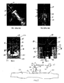
FIG. 1 is a view of a conventional RDU, connected to an exhaust flow path, showing a fluid supply connection thereof. -
FIG. 2 is a sectional view of a portion of the RDU ofFIG. 1 . -
FIG. 3 . is a perspective view of an RDU, provided in accordance with an embodiment of the present invention, having supply structure including a heated supply tube integrated into an injector cup. -
FIG. 4 is a sectional view of a portion of the RDU ofFIG. 3 . -
FIG. 5 is schematic view of the RDU ofFIG. 2 shown mounted to an exhaust flow path. - With reference to
FIG. 3 , a reductant delivery unit (RDU) for the delivery of AUS-32 to the engine exhaust is shown, generally indicated at 16, in accordance with an embodiment of the invention. TheRDU 16 is used in SCR exhaust after-treatment systems on vehicles. - The metering function of the
RDU 16 is performed by a specially adapted and packagedsolenoid fluid injector 18. Theinjector 18 also provides the spray preparation of the fluid in theexhaust path 13 that is upstream of an SCR catalytic converter 20 (FIG. 5 ). More particularly, aflange 22 of theRDU 16 withinjector 18 is mounted on aboss 24 of theexhaust path 13 preferably between an oxygencatalytic converter 26 and the SCRcatalytic converter 20. An advantage of using thefluid injector 18 is a reduction in cost afforded by using a high volume automotive component. - The
fluid injector 18 is preferably a gasoline, electrically operated, solenoid fluid injector such as the type disclosed inU.S. Patent No 6,685,112 and co-pendingU.S. Application No. 12/078,252, filed on March 28, 2008 . - The
injector 18 also has afluid inlet 28 and a fuel outlet 30 that extends through theflange 24. Theinlet 28 receives a source of urea solution or AUS-32 via asupply tube 29 from a tank 27 (FIG. 5 ). The fluid outlet 30 communicates with theexhaust flow path 13 so the solution can be injected directly into theexhaust flow path 13. Power is provided to theinjector 18 atelectrical connector 23. Theinjector 18 controls the flow rate of AUS-32 into theexhaust flow path 13 and also shuts-off the flow. - In accordance with an embodiment of the invention and as best shown in
FIG. 4 , thesupply tube 29 is made integral with asupply structure 32, generally indicated at 32, of theinjector 18. Thesupply structure 32 defines thefluid inlet 28 of theinjector 18. Thus, with the embodiment, there is no connection between thesupply tube 29 and thesupply structure 32 since they are integral and define a single member. As shown inFIG. 5 , aheat source 33 heats theentire supply tube 29 so that an entire volume of the urea solution delivered to theinlet 28 of theinjector 18 is heated. Therefore, this configuration provides an advantage over theconventional RDU 12 ofFIG. 2 since no time is needed to thaw fluid that would otherwise freeze in the unheated volume A ofFIG. 2 . - The
supply structure 32, preferably molded of plastic, includes anintegral flange 35, from which theintegral supply tube 29 extends, and an integral cup 37 that is sealed with respect to theinjector body 41 via an O-ring 39. Theflange 35 can be considered to be part of the cup 37. Thesupply structure 32 is mechanically joined to theRDU 16. In the embodiment, this mechanical coupling is achieved by providing multiple flexible tangs 34 extending from theflange 35. The tangs 34 are defined during molding of thesupply structure 32. Each tang 34 passes through opening 36 in aheat shield 38 of theRDU 16 and engages asurface 40 of theheat shield 38 at afirst end 42 thereof. Theheat shield 38 is generally cylindrical having anopen end 42. Theflange 35 closes theopen end 42. The heat shield is constructed and arranged to substantially surround theinjector 18 with the other, opposingend 44 of theheat shield 38 being coupled with theflange 22 that mounts to theboss 24. - In the event that servicing is required without disassembly of the
RDU 16 from theexhaust gas path 13, access openings to access the tangs 34 are provided in theheat shield 38 for a tool to push the tangs 34 back toward theopenings 36. Instead of providing the tangs, other removable securing means can be used such as, for example, bolts, clips, snap fits, etc. - In the event that servicing is not desirable, another embodiment would involve the molding of the
plastic supply structure 32 directly to theheat shield 38. Theheat shield 38 would subsequently be assembled to the rest of theRDU 16. - The foregoing preferred embodiments have been shown and described for the purposes of illustrating the structural and functional principles of the present invention, as well as illustrating the methods of employing the preferred embodiments and are subject to change without departing from such principles. Therefore, this invention includes all modifications encompassed within the scope of the following claims.
Claims (12)
- A reductant delivery unit (16) for selective catalytic reduction (SCR) after-treatment for vehicles, the reductant delivery unit (16) comprising:a solenoid fluid injector (18) constructed and arranged to be associated with an exhaust gas flow path (13) upstream of a SCR catalytic converter (20), the fluid injector (18) having a fluid inlet (28) and a fluid outlet (30), the fluid inlet (28) being constructed and arranged to receive a source of urea solution and the fluid outlet (30) being constructed and arranged to communicate directly with the exhaust flow path (13) so as to control injection of urea solution into the exhaust gas flow path (13), anda supply structure (32) defining the fluid inlet (28), the supply structure (32) including a portion (37) coupled to a body of the injector (18) and a supply tube (29), the supply tube (29) being constructed and arranged to be coupled with the source of urea solution to deliver urea solution to the fluid inlet (28),wherein the supply tube (29) is constructed and arranged to be heated by a heat source (33) so that an entire volume of the urea solution delivered to the fluid inlet (28) is heated,
characterized in that
the supply tube (29) is integral with the portion (37) to define a single member, and
the unit further comprises a heat shield (38) substantially surrounding the injector (18), the supply structure (29) being associated with the heat shield (38). - The unit (16) of claim 1, wherein the supply structure (32) includes an integral flange (35), the supply tube (29) being integral with the flange (35) and extending from the flange (35), the flange (35) being constructed and arranged to be removably coupled to the heat shield (38).
- The unit (16) of claim 2, wherein the flange (35) includes means for removably securing the flange (35) to an end of the heat shield (38).
- The unit (16) of claim 2 or 3, wherein the flange (35) includes a plurality of flexible tangs (34) extending there-from, an end of the heat shield (38) including a plurality of openings (36), a tang (34) being received in an associated opening (36), with the tangs (34) engaging a surface (40) of the heat shield (38) to removably secure the supply structure (32) to the heat shield (38).
- The unit (16) of claim 1 or 2, wherein the supply structure (32) is molded from plastic.
- The unit (16) of claim 2, wherein the heat shield (38) is generally cylindrical having an open end (42) with the flange (35) closing the open end (42).
- The unit of claim 4, wherein the heat shield (38) is generally cylindrical having an open end (42) with the flange (35) closing the open end (42), and wherein the heat shield (38) includes openings (36) constructed and arranged to access the tangs (34).
- The unit (16) of claim 1, wherein heat shield (38) has opposing ends (42, 44), a portion of the supply structure (32) being coupled to one of the ends (42), and a flange (22), constructed and arranged to be coupled to the exhaust gas flow path (13) being coupled to the other end (44).
- The unit (16) of claim 1, in combination with a heater (33) heating the entire supply tube.
- The unit (16) of one of the preceding claims, wherein the portion (37) is a cup.
- A method of ensuring that urea solution provided to a reductant delivery unit (RDU) (16) for selective catalytic reduction (SCR) after-treatment for vehicles is heated, the RDU (16) being mounted with respect to an exhaust gas flow path (13) so as to inject urea solution directly into the exhaust gas flow path (13), the method comprising:providing supply structure (32) defining a fluid inlet (28) of the RDU (16), the supply structure (32) including a supply tube (29) integral with a portion of the RDU (16) so as to define a single member, the supply tube (29) being coupled with the source of urea solution to deliver urea solution to the fluid inlet (28),providing a heat shield (38) to substantially surround the injector (16), andcoupling, in a removable manner, the supply structure (32) to the heat shield (38), andheating the supply tube (29) so that an entire volume of the urea solution delivered to the fluid inlet (28) of the RDU (16) is heated.
- The method of claim 11, wherein the step of providing the supply structure (32) includes molding the supply structure (32) from plastic.
Applications Claiming Priority (2)
| Application Number | Priority Date | Filing Date | Title |
|---|---|---|---|
| US98253107P | 2007-10-25 | 2007-10-25 | |
| PCT/US2008/006351 WO2009054865A1 (en) | 2007-10-25 | 2008-05-16 | Fluid supply connection for reductant delivery unit for selective catalytic reduction systems |
Publications (2)
| Publication Number | Publication Date |
|---|---|
| EP2205836A1 EP2205836A1 (en) | 2010-07-14 |
| EP2205836B1 true EP2205836B1 (en) | 2016-10-19 |
Family
ID=39689503
Family Applications (1)
| Application Number | Title | Priority Date | Filing Date |
|---|---|---|---|
| EP08767784.5A Active EP2205836B1 (en) | 2007-10-25 | 2008-05-16 | Fluid supply connection for reductant delivery unit for selective catalytic reduction systems |
Country Status (4)
| Country | Link |
|---|---|
| US (1) | US8087239B2 (en) |
| EP (1) | EP2205836B1 (en) |
| JP (1) | JP5091324B2 (en) |
| WO (1) | WO2009054865A1 (en) |
Families Citing this family (34)
| Publication number | Priority date | Publication date | Assignee | Title |
|---|---|---|---|---|
| DE102008038984A1 (en) * | 2008-08-13 | 2010-02-18 | Emitec Gesellschaft Für Emissionstechnologie Mbh | Method for selective heating of a reducing agent line |
| DE102009048514A1 (en) * | 2009-10-07 | 2011-04-14 | Emitec Gesellschaft Für Emissionstechnologie Mbh | Injektorhalterung |
| US8240137B2 (en) * | 2009-10-27 | 2012-08-14 | Cummins Filtration Ip, Inc. | Reductant injection and decomposition system |
| US8429903B2 (en) * | 2009-12-22 | 2013-04-30 | Caterpillar Inc. | Radial mounting for regeneration device |
| EP2339138A1 (en) * | 2009-12-24 | 2011-06-29 | Inergy Automotive Systems Research (Société Anonyme) | Flange equipped with a heating element |
| BR112012031838B1 (en) | 2010-06-15 | 2020-12-08 | Shaw Development, Llc | head unit and combination |
| US8822887B2 (en) | 2010-10-27 | 2014-09-02 | Shaw Arrow Development, LLC | Multi-mode heater for a diesel emission fluid tank |
| US8756921B2 (en) * | 2011-01-10 | 2014-06-24 | Paccar Inc | Reductant delivery device |
| US9115624B2 (en) * | 2011-07-29 | 2015-08-25 | Continental Automotive Systems, Inc. | Anti-rotation structure for a valve installed in an exhaust boss of a reductant delivery system |
| US20150004083A1 (en) * | 2012-01-26 | 2015-01-01 | International Engine Intellectual Property Company, Llc | Injector boss and system and method of injecting liquid into a gas stream |
| DE102012004727A1 (en) * | 2012-03-07 | 2013-09-12 | Emitec Gesellschaft Für Emissionstechnologie Mbh | Device for providing liquid additive |
| US9416709B2 (en) * | 2012-06-15 | 2016-08-16 | Continental Automotive Systems, Inc. | Coking resistant after-treatment dosing value |
| US9777859B2 (en) | 2012-11-19 | 2017-10-03 | Continental Automotive Systems, Inc. | Purging and sealing-reductant delivery unit for selective catalytic reduction systems |
| US9341295B2 (en) | 2013-03-27 | 2016-05-17 | Cummins Emission Solutions, Inc. | Fluid connectors for reductant systems |
| US8997463B2 (en) | 2013-04-17 | 2015-04-07 | Continental Automotive Systems, Inc. | Reductant delivery unit for automotive selective catalytic reduction with reducing agent heating |
| US9366167B2 (en) * | 2013-11-08 | 2016-06-14 | Continental Automotive Systems, Inc. | Injector water intrusion seal with blow out volume |
| USD729141S1 (en) | 2014-05-28 | 2015-05-12 | Shaw Development LLC | Diesel emissions fluid tank |
| USD729722S1 (en) | 2014-05-28 | 2015-05-19 | Shaw Development LLC | Diesel emissions fluid tank floor |
| FR3022582B1 (en) * | 2014-06-19 | 2016-07-01 | Peugeot Citroen Automobiles Sa | CATALYTIC SELECTIVE REDUCTION SYSTEM HAVING INSERT HEATER ON ITS INJECTOR |
| DE102015006517A1 (en) | 2015-04-01 | 2016-10-06 | Cummins Emission Solutions Inc. | Valve solenoid |
| US9828897B2 (en) * | 2015-04-30 | 2017-11-28 | Faurecia Emissions Control Technologies Usa, Llc | Mixer for a vehicle exhaust system |
| US9719397B2 (en) | 2015-04-30 | 2017-08-01 | Faurecia Emissions Control Technologies Usa, Llc | Mixer with integrated doser cone |
| WO2016176076A1 (en) * | 2015-04-30 | 2016-11-03 | Faurecia Emissions Control Technologies, Usa, Llc | Full rotation mixer |
| US9714598B2 (en) | 2015-04-30 | 2017-07-25 | Faurecia Emissions Control Technologies, Usa, Llc | Mixer with integrated doser cone |
| DE102015217673A1 (en) | 2015-09-15 | 2017-03-16 | Continental Automotive Gmbh | Injection device for metering a fluid and motor vehicle with such an injection device |
| WO2018075061A1 (en) | 2016-10-21 | 2018-04-26 | Faurecia Emissions Control Technologies Usa, Llc | Reducing agent mixer |
| FR3069280A1 (en) * | 2017-07-18 | 2019-01-25 | Psa Automobiles Sa | CATALYTIC SELECTIVE REDUCTION SYSTEM WITH THERMAL PROTECTION DEVICE |
| US10539057B2 (en) * | 2017-09-14 | 2020-01-21 | Vitesco Technologies USA, LLC | Injector for reductant delivery unit having reduced fluid volume |
| US10502112B2 (en) * | 2017-09-14 | 2019-12-10 | Vitesco Technologies USA, LLC | Injector for reductant delivery unit having fluid volume reduction assembly |
| US10947880B2 (en) | 2018-02-01 | 2021-03-16 | Continental Powertrain USA, LLC | Injector for reductant delivery unit having fluid volume reduction assembly |
| US10287948B1 (en) | 2018-04-23 | 2019-05-14 | Faurecia Emissions Control Technologies, Usa, Llc | High efficiency mixer for vehicle exhaust system |
| US10316721B1 (en) | 2018-04-23 | 2019-06-11 | Faurecia Emissions Control Technologies, Usa, Llc | High efficiency mixer for vehicle exhaust system |
| US10787946B2 (en) | 2018-09-19 | 2020-09-29 | Faurecia Emissions Control Technologies, Usa, Llc | Heated dosing mixer |
| US10767533B1 (en) * | 2019-02-28 | 2020-09-08 | Tenneco Automotive Operating Company Inc. | Reagent injector |
Family Cites Families (26)
| Publication number | Priority date | Publication date | Assignee | Title |
|---|---|---|---|---|
| DE3586265T2 (en) * | 1984-04-02 | 1992-12-17 | Hitachi Ltd | OXYGEN SENSOR. |
| US4742964A (en) * | 1985-10-30 | 1988-05-10 | Aisan Kogyo Kabushiki Kaisha | Electromagnetic fuel injector |
| JPH0199981U (en) * | 1987-12-25 | 1989-07-05 | ||
| US5224343A (en) * | 1990-02-22 | 1993-07-06 | Erno Raumfahrttechnik Gmbh | Constant fuel supply device for a thruster |
| NL1003980C2 (en) * | 1996-09-06 | 1998-03-13 | Vialle Beheer B V | Injection device. |
| DE19726392A1 (en) * | 1997-06-21 | 1998-12-24 | Bosch Gmbh Robert | Mixture dispenser |
| DE19739435A1 (en) * | 1997-09-09 | 1999-03-11 | Bosch Gmbh Robert | Sensor |
| US6047907A (en) | 1997-12-23 | 2000-04-11 | Siemens Automotive Corporation | Ball valve fuel injector |
| JP2000027627A (en) * | 1998-07-13 | 2000-01-25 | Hino Motors Ltd | Reducing agent thermal insulating device for exhaust gas cleaning catalyst, and exhaust emission control device provided with this thermal insulating device |
| US6526746B1 (en) * | 2000-08-02 | 2003-03-04 | Ford Global Technologies, Inc. | On-board reductant delivery assembly |
| US6481420B2 (en) * | 2001-01-30 | 2002-11-19 | Visteon Global Technologies, Inc. | Method and apparatus for maintaining the alignment of a fuel injector |
| JP3888518B2 (en) | 2001-09-10 | 2007-03-07 | 株式会社デンソー | Exhaust purification device |
| US6913210B2 (en) * | 2001-09-28 | 2005-07-05 | Holley Performance Products | Fuel injector nozzle adapter |
| DE10154421A1 (en) | 2001-11-06 | 2003-05-22 | Bosch Gmbh Robert | Method and device for reducing nitrogen oxides in an exhaust gas |
| US6814303B2 (en) * | 2002-04-03 | 2004-11-09 | Cleaire Advanced Emission Controls | Fluid-cooled mount for an injector |
| US6996976B2 (en) * | 2002-04-03 | 2006-02-14 | Cleaire Advanced Emmision Controls | Apparatus and method for mounting a device to a pipe |
| JP4262522B2 (en) * | 2003-05-28 | 2009-05-13 | 株式会社日立ハイテクノロジーズ | Exhaust gas treatment device for engine and exhaust gas treatment method |
| WO2005005797A2 (en) * | 2003-06-12 | 2005-01-20 | Donaldson Company, Inc. | Method of dispensing fuel into transient flow of an exhaust system |
| JP2005127318A (en) * | 2003-09-19 | 2005-05-19 | Nissan Diesel Motor Co Ltd | Engine exhaust emission control device |
| FR2874075B1 (en) | 2004-08-03 | 2007-11-09 | Espa Sarl | FLUID TRANSPORT TUBE |
| AT501091B1 (en) * | 2004-11-15 | 2006-12-15 | Pankl Emission Control Systems | EMISSION CONTROL DEVICE |
| US20060101810A1 (en) * | 2004-11-15 | 2006-05-18 | Angelo Theodore G | System for dispensing fuel into an exhaust system of a diesel engine |
| DE102004056791B4 (en) * | 2004-11-24 | 2007-04-19 | J. Eberspächer GmbH & Co. KG | exhaust system |
| JP2007113403A (en) * | 2005-10-18 | 2007-05-10 | Nissan Diesel Motor Co Ltd | Outside air temperature detecting device and exhaust emission control device |
| FR2897644B1 (en) | 2006-02-20 | 2011-08-05 | Renault Sas | DEVICE FOR DEPOLLUTING THE EXHAUST GASES OF AN INTERNAL COMBUSTION ENGINE |
| DE102006058402A1 (en) * | 2006-12-12 | 2008-06-19 | Bayerische Motoren Werke Ag | Device for admixing a reducing agent in an exhaust gas stream of an internal combustion engine |
-
2008
- 2008-05-16 EP EP08767784.5A patent/EP2205836B1/en active Active
- 2008-05-16 JP JP2010530990A patent/JP5091324B2/en active Active
- 2008-05-16 US US12/153,353 patent/US8087239B2/en not_active Expired - Fee Related
- 2008-05-16 WO PCT/US2008/006351 patent/WO2009054865A1/en active Application Filing
Also Published As
| Publication number | Publication date |
|---|---|
| US20090107126A1 (en) | 2009-04-30 |
| JP5091324B2 (en) | 2012-12-05 |
| EP2205836A1 (en) | 2010-07-14 |
| WO2009054865A1 (en) | 2009-04-30 |
| JP2011501042A (en) | 2011-01-06 |
| US8087239B2 (en) | 2012-01-03 |
Similar Documents
| Publication | Publication Date | Title |
|---|---|---|
| EP2205836B1 (en) | Fluid supply connection for reductant delivery unit for selective catalytic reduction systems | |
| US8997463B2 (en) | Reductant delivery unit for automotive selective catalytic reduction with reducing agent heating | |
| EP2134939B1 (en) | Reductant delivery unit for selective catalytic reduction | |
| KR102309229B1 (en) | Combustion engine | |
| US8528322B2 (en) | Reductant delivery unit for selective catalytic reduction with freeze accommodation structure | |
| US9689293B2 (en) | Reductant delivery unit for automotive selective catalytic reduction with optimized fluid heating | |
| EP2860369B1 (en) | System and device for reducing reductant deposit formation in exhaust aftertreatment systems | |
| US9273581B2 (en) | Purge system for reductant delivery unit for a selective catalytic reduction system | |
| CN104074576B (en) | Fluid connector for a reduction system | |
| US9074511B2 (en) | Reductant delivery unit for SCR systems having improved deposit resistance | |
| EP1989411A1 (en) | Ammonia precursor conversion reactor | |
| CN108301905B (en) | Ammonia urea double-injection system and control method thereof | |
| US12060822B2 (en) | Dosing module for use in aftertreatment systems for internal combustion engines | |
| WO2021021127A1 (en) | Systems and methods for decreasing time to reach light-off temperature | |
| EP3500741B1 (en) | Reductant dosing unit compact side feed inlet port | |
| WO2023244576A1 (en) | Exhaust conduit assembly | |
| WO2024006240A1 (en) | Doser mount for exhaust aftertreatment system | |
| GB2602209A (en) | Dosing module for use in aftertreatment systems for internal combustion engines |
Legal Events
| Date | Code | Title | Description |
|---|---|---|---|
| PUAI | Public reference made under article 153(3) epc to a published international application that has entered the european phase |
Free format text: ORIGINAL CODE: 0009012 |
|
| 17P | Request for examination filed |
Effective date: 20100525 |
|
| AK | Designated contracting states |
Kind code of ref document: A1 Designated state(s): AT BE BG CH CY CZ DE DK EE ES FI FR GB GR HR HU IE IS IT LI LT LU LV MC MT NL NO PL PT RO SE SI SK TR |
|
| AX | Request for extension of the european patent |
Extension state: AL BA MK RS |
|
| DAX | Request for extension of the european patent (deleted) | ||
| RAP1 | Party data changed (applicant data changed or rights of an application transferred) |
Owner name: CONTINENTAL AUTOMOTIVE SYSTEMS US, INC. |
|
| 17Q | First examination report despatched |
Effective date: 20150603 |
|
| RAP1 | Party data changed (applicant data changed or rights of an application transferred) |
Owner name: CONTINENTAL AUTOMOTIVE SYSTEMS, INC. |
|
| GRAP | Despatch of communication of intention to grant a patent |
Free format text: ORIGINAL CODE: EPIDOSNIGR1 |
|
| INTG | Intention to grant announced |
Effective date: 20160510 |
|
| GRAS | Grant fee paid |
Free format text: ORIGINAL CODE: EPIDOSNIGR3 |
|
| GRAA | (expected) grant |
Free format text: ORIGINAL CODE: 0009210 |
|
| AK | Designated contracting states |
Kind code of ref document: B1 Designated state(s): AT BE BG CH CY CZ DE DK EE ES FI FR GB GR HR HU IE IS IT LI LT LU LV MC MT NL NO PL PT RO SE SI SK TR |
|
| REG | Reference to a national code |
Ref country code: GB Ref legal event code: FG4D |
|
| REG | Reference to a national code |
Ref country code: CH Ref legal event code: EP |
|
| REG | Reference to a national code |
Ref country code: AT Ref legal event code: REF Ref document number: 838549 Country of ref document: AT Kind code of ref document: T Effective date: 20161115 |
|
| REG | Reference to a national code |
Ref country code: IE Ref legal event code: FG4D |
|
| REG | Reference to a national code |
Ref country code: DE Ref legal event code: R096 Ref document number: 602008046923 Country of ref document: DE |
|
| REG | Reference to a national code |
Ref country code: NL Ref legal event code: MP Effective date: 20161019 |
|
| REG | Reference to a national code |
Ref country code: LT Ref legal event code: MG4D |
|
| PG25 | Lapsed in a contracting state [announced via postgrant information from national office to epo] |
Ref country code: LV Free format text: LAPSE BECAUSE OF FAILURE TO SUBMIT A TRANSLATION OF THE DESCRIPTION OR TO PAY THE FEE WITHIN THE PRESCRIBED TIME-LIMIT Effective date: 20161019 |
|
| REG | Reference to a national code |
Ref country code: AT Ref legal event code: MK05 Ref document number: 838549 Country of ref document: AT Kind code of ref document: T Effective date: 20161019 |
|
| PG25 | Lapsed in a contracting state [announced via postgrant information from national office to epo] |
Ref country code: LT Free format text: LAPSE BECAUSE OF FAILURE TO SUBMIT A TRANSLATION OF THE DESCRIPTION OR TO PAY THE FEE WITHIN THE PRESCRIBED TIME-LIMIT Effective date: 20161019 Ref country code: NO Free format text: LAPSE BECAUSE OF FAILURE TO SUBMIT A TRANSLATION OF THE DESCRIPTION OR TO PAY THE FEE WITHIN THE PRESCRIBED TIME-LIMIT Effective date: 20170119 Ref country code: SE Free format text: LAPSE BECAUSE OF FAILURE TO SUBMIT A TRANSLATION OF THE DESCRIPTION OR TO PAY THE FEE WITHIN THE PRESCRIBED TIME-LIMIT Effective date: 20161019 Ref country code: GR Free format text: LAPSE BECAUSE OF FAILURE TO SUBMIT A TRANSLATION OF THE DESCRIPTION OR TO PAY THE FEE WITHIN THE PRESCRIBED TIME-LIMIT Effective date: 20170120 |
|
| REG | Reference to a national code |
Ref country code: FR Ref legal event code: PLFP Year of fee payment: 10 |
|
| PG25 | Lapsed in a contracting state [announced via postgrant information from national office to epo] |
Ref country code: AT Free format text: LAPSE BECAUSE OF FAILURE TO SUBMIT A TRANSLATION OF THE DESCRIPTION OR TO PAY THE FEE WITHIN THE PRESCRIBED TIME-LIMIT Effective date: 20161019 Ref country code: HR Free format text: LAPSE BECAUSE OF FAILURE TO SUBMIT A TRANSLATION OF THE DESCRIPTION OR TO PAY THE FEE WITHIN THE PRESCRIBED TIME-LIMIT Effective date: 20161019 Ref country code: IS Free format text: LAPSE BECAUSE OF FAILURE TO SUBMIT A TRANSLATION OF THE DESCRIPTION OR TO PAY THE FEE WITHIN THE PRESCRIBED TIME-LIMIT Effective date: 20170219 Ref country code: NL Free format text: LAPSE BECAUSE OF FAILURE TO SUBMIT A TRANSLATION OF THE DESCRIPTION OR TO PAY THE FEE WITHIN THE PRESCRIBED TIME-LIMIT Effective date: 20161019 Ref country code: PT Free format text: LAPSE BECAUSE OF FAILURE TO SUBMIT A TRANSLATION OF THE DESCRIPTION OR TO PAY THE FEE WITHIN THE PRESCRIBED TIME-LIMIT Effective date: 20170220 Ref country code: PL Free format text: LAPSE BECAUSE OF FAILURE TO SUBMIT A TRANSLATION OF THE DESCRIPTION OR TO PAY THE FEE WITHIN THE PRESCRIBED TIME-LIMIT Effective date: 20161019 Ref country code: BE Free format text: LAPSE BECAUSE OF FAILURE TO SUBMIT A TRANSLATION OF THE DESCRIPTION OR TO PAY THE FEE WITHIN THE PRESCRIBED TIME-LIMIT Effective date: 20161019 Ref country code: ES Free format text: LAPSE BECAUSE OF FAILURE TO SUBMIT A TRANSLATION OF THE DESCRIPTION OR TO PAY THE FEE WITHIN THE PRESCRIBED TIME-LIMIT Effective date: 20161019 Ref country code: FI Free format text: LAPSE BECAUSE OF FAILURE TO SUBMIT A TRANSLATION OF THE DESCRIPTION OR TO PAY THE FEE WITHIN THE PRESCRIBED TIME-LIMIT Effective date: 20161019 |
|
| REG | Reference to a national code |
Ref country code: DE Ref legal event code: R097 Ref document number: 602008046923 Country of ref document: DE |
|
| PG25 | Lapsed in a contracting state [announced via postgrant information from national office to epo] |
Ref country code: DK Free format text: LAPSE BECAUSE OF FAILURE TO SUBMIT A TRANSLATION OF THE DESCRIPTION OR TO PAY THE FEE WITHIN THE PRESCRIBED TIME-LIMIT Effective date: 20161019 Ref country code: SK Free format text: LAPSE BECAUSE OF FAILURE TO SUBMIT A TRANSLATION OF THE DESCRIPTION OR TO PAY THE FEE WITHIN THE PRESCRIBED TIME-LIMIT Effective date: 20161019 Ref country code: EE Free format text: LAPSE BECAUSE OF FAILURE TO SUBMIT A TRANSLATION OF THE DESCRIPTION OR TO PAY THE FEE WITHIN THE PRESCRIBED TIME-LIMIT Effective date: 20161019 Ref country code: RO Free format text: LAPSE BECAUSE OF FAILURE TO SUBMIT A TRANSLATION OF THE DESCRIPTION OR TO PAY THE FEE WITHIN THE PRESCRIBED TIME-LIMIT Effective date: 20161019 Ref country code: CZ Free format text: LAPSE BECAUSE OF FAILURE TO SUBMIT A TRANSLATION OF THE DESCRIPTION OR TO PAY THE FEE WITHIN THE PRESCRIBED TIME-LIMIT Effective date: 20161019 |
|
| PLBE | No opposition filed within time limit |
Free format text: ORIGINAL CODE: 0009261 |
|
| STAA | Information on the status of an ep patent application or granted ep patent |
Free format text: STATUS: NO OPPOSITION FILED WITHIN TIME LIMIT |
|
| PG25 | Lapsed in a contracting state [announced via postgrant information from national office to epo] |
Ref country code: BG Free format text: LAPSE BECAUSE OF FAILURE TO SUBMIT A TRANSLATION OF THE DESCRIPTION OR TO PAY THE FEE WITHIN THE PRESCRIBED TIME-LIMIT Effective date: 20170119 Ref country code: LU Free format text: LAPSE BECAUSE OF NON-PAYMENT OF DUE FEES Effective date: 20170531 |
|
| 26N | No opposition filed |
Effective date: 20170720 |
|
| PG25 | Lapsed in a contracting state [announced via postgrant information from national office to epo] |
Ref country code: SI Free format text: LAPSE BECAUSE OF FAILURE TO SUBMIT A TRANSLATION OF THE DESCRIPTION OR TO PAY THE FEE WITHIN THE PRESCRIBED TIME-LIMIT Effective date: 20161019 |
|
| REG | Reference to a national code |
Ref country code: CH Ref legal event code: PL |
|
| GBPC | Gb: european patent ceased through non-payment of renewal fee |
Effective date: 20170516 |
|
| PG25 | Lapsed in a contracting state [announced via postgrant information from national office to epo] |
Ref country code: MC Free format text: LAPSE BECAUSE OF FAILURE TO SUBMIT A TRANSLATION OF THE DESCRIPTION OR TO PAY THE FEE WITHIN THE PRESCRIBED TIME-LIMIT Effective date: 20161019 |
|
| REG | Reference to a national code |
Ref country code: IE Ref legal event code: MM4A |
|
| PG25 | Lapsed in a contracting state [announced via postgrant information from national office to epo] |
Ref country code: CH Free format text: LAPSE BECAUSE OF NON-PAYMENT OF DUE FEES Effective date: 20170531 Ref country code: LI Free format text: LAPSE BECAUSE OF NON-PAYMENT OF DUE FEES Effective date: 20170531 |
|
| PG25 | Lapsed in a contracting state [announced via postgrant information from national office to epo] |
Ref country code: LU Free format text: LAPSE BECAUSE OF NON-PAYMENT OF DUE FEES Effective date: 20170516 |
|
| PG25 | Lapsed in a contracting state [announced via postgrant information from national office to epo] |
Ref country code: IE Free format text: LAPSE BECAUSE OF NON-PAYMENT OF DUE FEES Effective date: 20170516 Ref country code: GB Free format text: LAPSE BECAUSE OF NON-PAYMENT OF DUE FEES Effective date: 20170516 |
|
| REG | Reference to a national code |
Ref country code: FR Ref legal event code: PLFP Year of fee payment: 11 |
|
| PG25 | Lapsed in a contracting state [announced via postgrant information from national office to epo] |
Ref country code: MT Free format text: LAPSE BECAUSE OF NON-PAYMENT OF DUE FEES Effective date: 20170516 |
|
| PG25 | Lapsed in a contracting state [announced via postgrant information from national office to epo] |
Ref country code: HU Free format text: LAPSE BECAUSE OF FAILURE TO SUBMIT A TRANSLATION OF THE DESCRIPTION OR TO PAY THE FEE WITHIN THE PRESCRIBED TIME-LIMIT; INVALID AB INITIO Effective date: 20080516 |
|
| PGFP | Annual fee paid to national office [announced via postgrant information from national office to epo] |
Ref country code: DE Payment date: 20190531 Year of fee payment: 12 |
|
| PG25 | Lapsed in a contracting state [announced via postgrant information from national office to epo] |
Ref country code: CY Free format text: LAPSE BECAUSE OF NON-PAYMENT OF DUE FEES Effective date: 20161019 |
|
| PG25 | Lapsed in a contracting state [announced via postgrant information from national office to epo] |
Ref country code: TR Free format text: LAPSE BECAUSE OF FAILURE TO SUBMIT A TRANSLATION OF THE DESCRIPTION OR TO PAY THE FEE WITHIN THE PRESCRIBED TIME-LIMIT Effective date: 20161019 |
|
| REG | Reference to a national code |
Ref country code: DE Ref legal event code: R119 Ref document number: 602008046923 Country of ref document: DE |
|
| PG25 | Lapsed in a contracting state [announced via postgrant information from national office to epo] |
Ref country code: DE Free format text: LAPSE BECAUSE OF NON-PAYMENT OF DUE FEES Effective date: 20201201 |
|
| P01 | Opt-out of the competence of the unified patent court (upc) registered |
Effective date: 20230530 |
|
| PGFP | Annual fee paid to national office [announced via postgrant information from national office to epo] |
Ref country code: IT Payment date: 20230526 Year of fee payment: 16 |
|
| PGFP | Annual fee paid to national office [announced via postgrant information from national office to epo] |
Ref country code: FR Payment date: 20240529 Year of fee payment: 17 |