EP1480496B1 - Controllable lighting equipment with a second communication protocol, and apparatus therefor - Google Patents
Controllable lighting equipment with a second communication protocol, and apparatus therefor Download PDFInfo
- Publication number
- EP1480496B1 EP1480496B1 EP04009349A EP04009349A EP1480496B1 EP 1480496 B1 EP1480496 B1 EP 1480496B1 EP 04009349 A EP04009349 A EP 04009349A EP 04009349 A EP04009349 A EP 04009349A EP 1480496 B1 EP1480496 B1 EP 1480496B1
- Authority
- EP
- European Patent Office
- Prior art keywords
- ballast
- communication protocol
- lamp
- control
- ballasts
- Prior art date
- Legal status (The legal status is an assumption and is not a legal conclusion. Google has not performed a legal analysis and makes no representation as to the accuracy of the status listed.)
- Revoked
Links
Images


Classifications
-
- H—ELECTRICITY
- H05—ELECTRIC TECHNIQUES NOT OTHERWISE PROVIDED FOR
- H05B—ELECTRIC HEATING; ELECTRIC LIGHT SOURCES NOT OTHERWISE PROVIDED FOR; CIRCUIT ARRANGEMENTS FOR ELECTRIC LIGHT SOURCES, IN GENERAL
- H05B41/00—Circuit arrangements or apparatus for igniting or operating discharge lamps
- H05B41/14—Circuit arrangements
- H05B41/26—Circuit arrangements in which the lamp is fed by power derived from dc by means of a converter, e.g. by high-voltage dc
- H05B41/28—Circuit arrangements in which the lamp is fed by power derived from dc by means of a converter, e.g. by high-voltage dc using static converters
- H05B41/295—Circuit arrangements in which the lamp is fed by power derived from dc by means of a converter, e.g. by high-voltage dc using static converters with semiconductor devices and specially adapted for lamps with preheating electrodes, e.g. for fluorescent lamps
-
- H—ELECTRICITY
- H05—ELECTRIC TECHNIQUES NOT OTHERWISE PROVIDED FOR
- H05B—ELECTRIC HEATING; ELECTRIC LIGHT SOURCES NOT OTHERWISE PROVIDED FOR; CIRCUIT ARRANGEMENTS FOR ELECTRIC LIGHT SOURCES, IN GENERAL
- H05B47/00—Circuit arrangements for operating light sources in general, i.e. where the type of light source is not relevant
- H05B47/10—Controlling the light source
- H05B47/175—Controlling the light source by remote control
- H05B47/18—Controlling the light source by remote control via data-bus transmission
Definitions
- the invention is directed to electronic ballasts for lamps, so as ballasts for discharge lamps or LEDs (which are here subsumed under the term "lamp") or transformers or relays for incandescent lamps. It also relates, in addition to or in combination therewith, to control devices for controlling electronic ballasts for lamps.
- the ballast or the control unit should be designed for digital communication, the ballast should therefore be controlled digitally using a communication protocol and the controller for a digital control of a ballast be designed with a communication protocol.
- ballasts and control devices are known per se.
- DALI digital addressable lighting interface
- the US 2002/0154025 A1 discloses a method and a device for the wireless addressing of lighting systems
- EP 0 714 224 A2 describes a method and a device for controlling lighting systems.
- ballasts also installed in combination with a lamp, such as an energy-saving lamp, and control units are particularly used in larger lighting systems, in which complex control functions can be achieved by digital addressing.
- the present invention is based on the technical problem of providing an improved ballast and an improved control unit, which are designed for a digital control communication with a communication protocol.
- the invention is directed to an electronic ballast and a control device for controlling an electronic ballast, which are each designed for a digital control of the ballast with a second additional communication protocol.
- the basic idea of the invention is therefore that it offers particular advantages, the devices mentioned, wherein the term device hereinafter means both the control device and the ballast according to the invention to interpret two different communication protocols out.
- the term device hereinafter means both the control device and the ballast according to the invention to interpret two different communication protocols out.
- an inventive device can then communicate so via an additional protocol and exchange further information accordingly.
- the invention has the considerable advantage that this increase in performance without departing from a predetermined and in practice possibly very common or determined by a certain standardization Protocol can be achieved.
- the devices according to the invention continue to remain compatible with the first protocol.
- An additional aspect may be that the second communication protocol, in contrast to a first protocol standardized by manufacturer agreement or otherwise, is manufacturer-specific or in an individual case even application-specific or customer-specific can be set and possibly also with less effort or shorter time intervals changed and in particular can be extended.
- the invention thus goes the way of a "two-pronged" communication between the devices.
- the devices according to the invention are of course present in combination.
- the invention is therefore directed in particular to lighting systems in which both the ballasts and control devices are designed according to the invention.
- advantages are already achieved if only a single device of the invention corresponds or if in a lighting system only the ballasts or control units or a part thereof correspond to the invention.
- this results in an extended retrofittability and functional extension by subsequent connection of suitable inventive devices (control devices to existing ballasts or vice versa).
- the individual devices can be read or reprogrammed by an external service device designed for the second communication protocol without being restricted by the first protocol.
- An inventive ballast is preferably equipped so that it can determine automatically upon receipt of a drive signal to which communication protocol the drive signal belongs, and accordingly can set to an evaluation of this drive signal.
- the invention would be so executable that the ballast can be switched by an external signal or a switch on the ballast or in a similar manner from the first to the second communication protocol or vice versa.
- a control unit is preferably equipped such that it can send drive signals in accordance with the first communication protocol and further drive signals in accordance with the second communication protocol "at the same time".
- "at the same time” means that the transmission takes place without switching by external action, that is to say either actually in parallel, for instance at different carrier frequencies, or in some way time-interleaved, ie with a change according to specific bit numbers or specific command numbers.
- the control unit transmits drive signals in a time-interleaved manner in accordance with both communication protocols, the signals alternating in a command-specific manner without a fixed predetermined alternating sequence. The alternation takes place as needed.
- commands of the second protocol are interposed as needed between commands of the first protocol.
- the already mentioned preferred ballast independently make an assignment to the protocols.
- a preferred way of distinguishing between the protocols is that the corresponding instruction words have different word lengths.
- the instruction words Preferably, however, the instruction words have identical start bits to initially enable synchronization or triggering.
- the communication protocols may differ in their stop bits. With simultaneous use of the two differentiation possibilities, an increased recognition reliability is ensured.
- the communication protocols according to the invention are preferred biphasencodiert.
- an ascending level jump can mean a logical 0 and a falling level jump a logical 1, and vice versa.
- a particular utility of the invention is to read devices according to the invention by utilizing the second, for example, manufacturer-specific communication protocol with regard to defect analysis or operational history and reprogramming with regard to maintenance or update.
- the contents of an electronic memory of a microcontroller can be read out, for example, in terms of operating hours or error messages, or can be described with a more up-to-date operating software or operating software adapted to a newly used lamp type.
- the present invention in a further aspect, more specifically, it is a lighting system in which at least one gas discharge lamp with preheatable electrodes is contained.
- electrodes are preheatable to improve ignition conditions and extend the life of the discharge lamp. Turning on such a discharge lamp is done via a preheat and subsequent ignition in the lamp.
- the invention provides in this respect, by the control unit to the ballast to send a ready command, down to the ballast operates the discharge lamp in such a way that it heats the electrodes at non-burning discharge lamp, so that the control unit by a switch-on the discharge lamp whose Electrodes are heated, can ignite again without delay by a preheating.
- the delay caused by the preheat time can be detrimental between a turn-on command and the actual light generation. This applies in particular to the field of stage and effect lighting, but may also be of interest in other contexts, especially with more complex timing schemes.
- the invention provides for a standby state of the ballast and consequently of the discharge lamp in which the electrodes continue to be heated.
- the heating continues at least to the extent that a new start without damaging the lamp and virtually no time delay is possible.
- This standby state is caused by a standby command provided for this purpose being sent by the control unit to the ballast.
- the readiness command can have the consequence, on the one hand, that the ballast does not convert a subsequent switch-off command in the sense of a complete switch-off, but rather in the sense of a transition to the standby state, ie, the electrodes continue to be heated when the discharge lamp is not burning.
- the ready command can also be received when the lamp is switched off and have a preheating or heating of the electrodes until the next switch-on with a corresponding immediate start result.
- the standby command is simultaneously a turn-off, so is sent to a ballast of a burning discharge lamp, whereupon the discharge lamp goes out, but the electrodes remain heated.
- the invention thus has the overall advantage of enabling a quasi-instantaneous instant start of discharge lamps in lighting systems by introducing a further command and a corresponding standby state as needed.
- the standby state or electrode heating process following the standby command is limited in time and is switched off again, if after a predetermined time no switch-on or renewing another standby command has been received.
- the standby state can be prevented from being unnecessarily or even indefinitely long in case of a mis-control or an unexpected end of operation of the lighting system.
- This time limit is preferably carried out by the ballast and not by the control unit.
- the ballast in the case of a switch-on command, the ballast is queried as to whether the standby state, that is to say the electrode heating process, is still continuing. Then, depending on the result of the query, a preheat operation may be inserted before a restart or not.
- This query is preferably carried out by the ballast itself, so it checks the state of the lamp operated by it or its own operating state.
- the standby state can be terminated even before the expiration of the time limit or, if this feature is not provided, at all by a standby off command.
- An inventive ballast is configured accordingly, that is configured to respond to the standby command according to the invention in the manner described.
- An inventive control device is designed to be able to send a described ready command, thus providing the relevant additional command.
- a lighting system according to the invention has at least one corresponding ballast and at least one corresponding control unit in order to be able to work in accordance with the described method.
- the invention further includes in this respect the aspect that the ballasts are provided before installation in the lighting system with individual for the respective ballasts, externally signal technically addressable codes, read these codes during installation of the lighting system and the control unit are entered so that they the control unit are assigned to the installation positions of the respective ballasts, the control unit assigns respective control addresses to the respective ballasts for activation and the control unit controls the ballasts using the control addresses.
- the invention also relates to a correspondingly manufactured and put into operation lighting system and finally to a manufacturing method for a ballast, in which the ballast is provided in a manner adapted to the invention with an externally signal technically addressable code.
- the invention provides that during installation of the lighting system, d. H.
- the code is read out, that is detected in any way to enter it together with the installation position to the control unit.
- the installer may write off a code written thereon and create an appropriately coded installation plan that can be used during programming of the controller.
- he can also type the code into a file or, for example, read it with a bar code reader or record in other ways data or electrical.
- the controller is programmed, there is already an association between the codes of the ballasts and their positions in the lighting system, because the installer has made this assignment already during assembly of the ballasts, so at this time in knowledge of the positions of the lighting system.
- the control unit now only has to assign control addresses to the respective ballasts, which could also be the codes themselves and in the future will address and control the ballasts with these control addresses.
- ballasts and not lamps, although in the lighting system ultimately the lamp operation should be controlled.
- pure lamps without ballast per se are not addressable.
- ballast here means the operating devices, which are, as it were, directly assigned to the lamps, that is to say those devices which are only connected via electrical lines or other simple electrical devices without their own data-related function and meaning, are connected to the lamps. In this sense, therefore, the ballasts are connected directly to the lamps.
- the connections between the control unit and the ballasts can be without line, that is to say based on radio links, for example.
- lighting system is to be understood here very generally and is not limited to lighting in the classical sense, so the above-mentioned examples of room or exterior lighting with conventional lamps. Rather, z. B. also LED applications are installed according to the invention, provided appropriate control devices and ballasts are present.
- the term “externally signal-technically addressable” is also to be understood generally and may mean, on the one hand, that the codes in the ballasts can be read from the outside, so that the control unit or a service unit can interrogate which code has a ballast.
- responsive can also mean that the ballasts are code-specific selectable, so the corresponding ballast "addressed” when a control command is received with the appropriate code.
- the inventive method thus has the advantage of a clear and relatively labor-intensive installation and address assignment.
- these benefits also apply to the appropriately manufactured and commissioned lighting system.
- these advantages are also transferred to the appropriate ballasts and thus to a manufacturing process for a ballast in which an integratable in the above manner in an address-sensitive lighting system ballast with one of outside signal technically addressable code is provided in the above sense.
- a preferred embodiment of the invention provides that the codes of the ballasts are addressed via lines to the ballasts from the outside, which lines connect the ballasts to the controller.
- these cables can also be optical lines, such as fiber optic cables, in addition to conventional electrical lines.
- the codes contained in the ballasts can there preferably be stored in a semiconductor memory. Furthermore, according to the invention, they can preferably be mounted on the ballast in an optically readable manner, that is to say in the described manner as a barcode print or sticker or as an alphanumeric label.
- a particularly preferred application of the invention provides discharge lamps and / or LEDs as lamps, whereby, of course, other types of lamps can occur in addition.
- Discharge lamps and LEDs or LED modules are within lighting systems i. d. R. can not be operated without ballasts.
- relays or dimmers for incandescent lamps may be ballasts within the meaning of the invention.
- More complex control options in lighting systems are in demand especially in the field of interior lighting, so that the invention is preferably directed to this area. Examples are conference and event rooms, theaters and the like.
- the lighting system according to the invention can in turn be part of a larger system, the control unit can therefore in turn be connected to a building control system in the sense of a more general home automation control and controlled by this system.
- the associated with the mentioned addressing function commands can of course ultimately by the Building control system generated and entered by the lighting system control unit only in the lighting system.
- the invention also makes it possible to upgrade an existing lighting system in a particularly simple manner.
- the inventive method thus also includes the case that an existing lighting system is expanded by adding at least one ballast and thus produced in the expanded form. Both the case is conceivable that the previous smaller lighting system was already designed according to the invention, as well as the case that by conventional retrofitting or replacement of the controller, a conventional lighting system is made compatible with the inventive method. The conventional smaller lighting system then already has an address assignment, so that the advantages of the invention for the present or future expansion stages can be used.
- ballast code date and / or place of manufacture of the ballast and / or information on the ballast type, the connectable lamp type or the connectable Number of lamps contains or even exclusively consists of this information.
- software updates in microcontroller controls or in the search of parts to be replaced or to be tested parts of the affected ballasts can be particularly easily selected in this way.
- Fig. 1 shows a schematic block diagram of a ballast according to the invention for a discharge lamp in a lighting system.
- the numbered with 2 discharge lamp is started and operated by the figured with 1 electronic ballast and has in particular preheatable electrodes.
- the electronic ballast (in the following for the sake of brevity ECG) has, on the one hand, a mains connection 31 for connecting a mains supply line 32 and, on the other hand, a control connection 41 for connecting a control line 42.
- the power supply 31 leads via a radio-protection filter 11 and a rectifier with power factor correction circuit (PFC circuit) to a smoothing capacitor 13, which supplies an inverter 14, such as half-bridge topology, with DC power.
- the inverter 14 essentially contains the functional blocks lamp circuit 14a and heating circuit 14b and is connected to the lamp 2 via a transformer 15 with taps for heating the electrodes (as indicated graphically).
- control terminal 41 is connected to a digital electronic interface 17 and provides via this a control signal to a microcontroller 16 with memory 16a.
- This microcontroller 16 is used to control the inverter, d. H. ultimately, to control lamp operation including preheat, ignition and dimming.
- Fig. 2 again shows in a schematic way a lighting system according to the invention, wherein with 1-11 to 1-n and 1-21 to 1-m ECGs of in Fig. 1 of the type shown and having discharge lamps corresponding to the lamp 2 connected thereto at 2-11 to 2-n and 2-21 to 2-m Fig. 1 are designated.
- the approximately in the middle of the Fig. 2 Dashed horizontal line symbolically divides a first space above it from a second space below it.
- Some of the ECGs and lamps are located aiso in the first room and another in the second room. In reality, of course, more rooms and possibly also other electronic ballasts and lamps are provided so that you can Fig. 2 can continue thinking downwards.
- control unit 3a In the left area are provided with 7a and 7b controls for operating the lighting system, the controls are connected to two controllers 3a and 3b. Both controllers are in this example in the first room. There are also the controls 7a and 7b top left. However, there is a similar second operating element 7a, which is interconnected with the upper control element 7a and has identical functions, also in the second room.
- the control unit 3a thus fulfills functions that can be operated from both rooms, while the control unit 3b is accessible only in the first room.
- the control devices 3a and 3b are connected with control signal outputs to two bus signal lines 42, whose branches of in Fig. 1 drawn control line 42 correspond.
- the control signal line 42 is thus bipolar and designed as a pure bus, because both controllers 3a and 3b and all ECGs are connected to it.
- the respective network power supply 32 of the ECGs is in Fig. 2 not shown and carried out according to the invention not of interest principles locally. It is thus clear that functions of the individual lamps or electronic ballasts can be controlled purely by signal technology via a bus line 42 via the operating elements and control units, wherein the control signals will be discussed in more detail below.
- Fig. 3 shows an alternative to Fig. 2 , wherein identical reference numerals designate corresponding elements.
- a control unit 3 is used for inputting control commands in the control signal line 42, which in turn receives commands via a bus system in the form of the symbolic line 6 of a more general building control system.
- the control unit 3 designates the interface or the gateway between the building technology control system shown on the left side thereof by the line 6 and the actual lighting installation beginning with the control unit 3.
- the design of the building control system and in particular the command input are not shown here in detail; it is only a question of demonstrating that the lighting system according to the invention can be integrated into such a system.
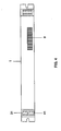
- Fig. 4 shows a concrete example of an ECG 1 according to the Fig. 1-3 , Here, a cuboidal sheet metal housing is shown, in which the basis Fig. 1 closer circuit explained is housed. On the left, one recognizes the network connection 31 and the control connection 41; on the right four individual connections for the lamp 2 are shown, but not numbered.
- the electronic ballast 1 can easily be fixed in luminaires via visible recesses on the left and right.
- the TOE has 1 Fig. 4 an imprint 8 with a barcode and an alphanumeric representation of the corresponding code.
- the corresponding code is in the in Fig. 1 shown semiconductor memory 16a of the microcontroller 16 stored in the ECG. It reflects the place of manufacture, time and line (at the factory) of the TOE and can also contain information about the device type, such as the number of lamp outputs and operable lamp types.
- the installer can now in a correspondingly generated installation plan on paper and / or a corresponding file (reading by a bar code reader or typing in a notebook) between the predetermined by its installation position of the individual electronic ballast 1 in the lighting system according to Fig. 2 or Fig. 3 (ie whether it is there, for example, the electronic ballast 1-12 to the discharge lamp 2-12, for example, the back right on the ceiling of the first room or the ECG 1-21 to the discharge lamp 2-21, for example, on the flur departmenten wall of second space), and make an assignment to the codes 8 and make this database available to the programmer of the control units 3.
- the control unit (s) is now informed which ECG code 8 corresponds to which position.
- the corresponding ECG 1 is then signal-technically addressable, ie responds to appropriate commands with the correct code input or indicates the code to general request the control unit off.
- the control unit can therefore assign the respective ECGs 1 or codes 8 internal control addresses (in principle, also use the existing codes 8 as addresses).
- Fig. 5a and 5b schematically show the word structure (frame) of control commands between the control units 3 and ECGs 1 according to the two biphase-coded protocols.
- the biphase coding is explained, wherein the left falling edge is to correspond from the high level to the low level of the logical 1 and the right complementary rising edge to the logical zero.
- the upper protocol 1 in this embodiment corresponds to the already mentioned DALI protocol and consists of a start bit (logical 1) and subsequently 16 information bits no. 15-0 and finally a stop bit, which is a two bit lengths (plotted as T BIT ) persisting high level equivalent. MSB and LSB stand for the most significant or least significant bit.
- the second protocol namely in the present case OSRAMspecific communication protocol, drawn, which corresponds to the start bit the DALI protocol 1, but has a lengthened by one bit word length and an inverse inverse stop bit.
- the ECGs 1 can therefore unambiguously determine whether it is a DALI command or an OSRAM-specific command both by means of the word length and by the nature of the stop bit.
- Fig. 6 shows one of the various uses of the additional communication protocol, namely with a vendor-specific standby command.
- Links are the meanings of horizontal running Plotted diagram lines, wherein a high level of the line means a "turned on” and a low level means “off". In the illustrated diagram, the time sequence running from left to right thus begins with the standby mode switched off.
- a helical preheat state for the time duration T P first follows with an on command, to which duration an ignition and thus a lamp operation (lowest horizontal line in the diagram jumps to "on”) follows.
- an inventive standby command takes place (top line jumps to "on"), which initially does not change the lamp operation itself. He has the consequence, however, that after a again indeterminate, but not over a certain maximum duration time, following Ausbetation leads on the one hand to an end of the lamp operation, but on the other hand at the same time to a restart of the filament heating. If after a certain time, again not over a certain maximum time, a new command follows, the lamp can unleash immediately in contrast to the first command (far left) without having to wait for a new preheat phase T P.
- a new standby command follows during turn-on, which in turn leads to a transition to the standby state, that is, to the filament heater, to the next exit command and the simultaneous lamp end of operation.
- the standby state ie the filament heating
- the standby state is to end after another specific time because either after the standby command or after the command has expired a time period exceeding a certain predetermined maximum time or a command to terminate the standby state has been received.
- the filament heater goes out. Consequently, as shown on the right-hand side, a preheat preheat must be carried out again at the next command.
- the lighting system is thus able to enable an immediate restart of the lamp with virtually no time delay by switching on a standby state by the standby command provided with the second protocol. This comes to light systems according to the invention, especially in the field of effect lighting to good.
Abstract
Description
Die Erfindung richtet sich auf elektronische Vorschaltgeräte für Lampen, also etwa Vorschaltgeräte für Entladungslampen oder auch LEDs (die hier unter dem Begriff "Lampe" subsumiert werden) oder Transformatoren oder Relais für Glühlampen. Sie bezieht sich ferner daneben oder in Kombination damit auch auf Steuergeräte zur Ansteuerung von elektronischen Vorschaltgeräten für Lampen. Das Vorschaltgerät bzw. das Steuergerät sollen für eine digitale Kommunikation ausgelegt sein, das Vorschaltgerät soll also digital unter Verwendung eines Kommunikationsprotokolls ansteuerbar sein und das Steuergerät für eine digitale Ansteuerung eines Vorschaltgeräts mit einem Kommunikationsprotokoll ausgelegt sein.The invention is directed to electronic ballasts for lamps, so as ballasts for discharge lamps or LEDs (which are here subsumed under the term "lamp") or transformers or relays for incandescent lamps. It also relates, in addition to or in combination therewith, to control devices for controlling electronic ballasts for lamps. The ballast or the control unit should be designed for digital communication, the ballast should therefore be controlled digitally using a communication protocol and the controller for a digital control of a ballast be designed with a communication protocol.
Solche Vorschaltgeräte und Steuergeräte sind an sich bekannt. Insbesondere haben verschiedene Hersteller sich jüngst auf ein gemeinsames Kommunikationsprotokoll unter der Bezeichnung "digital addressable lighting interface" (= "DALI") geeinigt.Such ballasts and control devices are known per se. In particular, several manufacturers have recently agreed on a common communication protocol called "digital addressable lighting interface" (= "DALI").
Die
Die entsprechenden Vorschaltgeräte, auch in Kombination mit einer Lampe verbaut, etwa als Energiesparlampe, und Steuergeräte sind insbesondere in größeren Lichtanlagen einsetzbar, in denen komplexe Steuerfunktionen durch digitale Adressierung erzielt werden können.The corresponding ballasts, also installed in combination with a lamp, such as an energy-saving lamp, and control units are particularly used in larger lighting systems, in which complex control functions can be achieved by digital addressing.
Der vorliegenden Erfindung liegt das technische Problem zu Grunde, ein verbessertes Vorschaltgerät und ein verbessertes Steuergerät anzugeben, die für eine digitale Steuerkommunikation mit einem Kommunikationsprotokoll ausgelegt sind.The present invention is based on the technical problem of providing an improved ballast and an improved control unit, which are designed for a digital control communication with a communication protocol.
Die Erfindung richtet sich auf ein elektronisches Vorschaltgerät und ein Steuergerät zur Steuerung eines elektronischen Vorschaltgerät, die jeweils für eine digitale Ansteuerung des Vorschaltgeräts mit einem zweiten zusätzlichen Kommunikationsprotokoll ausgelegt sind.The invention is directed to an electronic ballast and a control device for controlling an electronic ballast, which are each designed for a digital control of the ballast with a second additional communication protocol.
Der Grundgedanke der Erfindung besteht also darin, dass es besondere Vorteile bietet, die erwähnten Geräte, wobei der Begriff Gerät im Folgenden sowohl das Steuergerät als auch das Vorschaltgerät gemäß der Erfindung meint, auf zwei verschiedene Kommunikationsprotokolle hin auszulegen. Neben einem vorgegebenen Protokoll, etwa dem erwähnten DALI-Protokoll, kann ein erfindungsgemäßes Gerät dann also über ein zusätzliches Protokoll kommunizieren und entsprechend weitere Informationen austauschen.The basic idea of the invention is therefore that it offers particular advantages, the devices mentioned, wherein the term device hereinafter means both the control device and the ballast according to the invention to interpret two different communication protocols out. In addition to a given protocol, such as the aforementioned DALI protocol, an inventive device can then communicate so via an additional protocol and exchange further information accordingly.
Neben der schieren Erweiterung der Kommunikationsmöglichkeiten über die durch das erste Kommunikationsprotokoll gegebene Steigerung der technischen Leistungsfähigkeit hinaus, hat die Erfindung dabei den erheblichen Vorteil, dass diese Leistungssteigerung ohne ein Abweichen von einem vorgegebenen und in der Praxis womöglich stark verbreiteten bzw. durch eine gewisse Standardisierung festgelegten Protokoll erzielt werden kann. Die erfindungsgemäßen Geräte bleiben nämlich weiterhin mit dem ersten Protokoll kompatibel. Ein zusätzlicher Aspekt kann darin liegen, dass das zweite Kommunikationsprotokoll im Gegensatz zu einem nach Herstellerübereinkunft oder in anderer Weise standardisierten ersten Protokoll herstellerspezifisch oder im Einzelfall sogar anwendungsspezifisch oder kundenspezifisch festgelegt werden kann und möglicherweise auch mit geringerem Aufwand oder kürzeren Zeitabständen geändert und insbesondere erweitert werden kann.In addition to the sheer expansion of the communication options over the given by the first communication protocol increase in technical performance, the invention has the considerable advantage that this increase in performance without departing from a predetermined and in practice possibly very common or determined by a certain standardization Protocol can be achieved. The devices according to the invention continue to remain compatible with the first protocol. An additional aspect may be that the second communication protocol, in contrast to a first protocol standardized by manufacturer agreement or otherwise, is manufacturer-specific or in an individual case even application-specific or customer-specific can be set and possibly also with less effort or shorter time intervals changed and in particular can be extended.
Dabei bleibt es jedoch bei einer uneingeschränkten Funktionsfähigkeit der Kommunikation über das erste Protokoll, also insbesondere bei einer einwandfreien Erstellbarkeit bzw. Verständlichkeit der zugehörigen Befehle. Statt der technisch im Grunde einfacheren und direkteren Ersetzung eines abzuwandelnden oder zu erweiternden Protokolls durch ein anderes, geht die Erfindung also den Weg einer "zweigleisigen" Kommunikation zwischen den Geräten.However, it remains at an unrestricted functionality of the communication on the first protocol, so in particular at a flawless operability or intelligibility of the associated commands. Instead of the technically basically simpler and more direct replacement of a protocol to be modified or extended by another, the invention thus goes the way of a "two-pronged" communication between the devices.
Vorzugsweise sind die erfindungsgemäßen Geräte natürlich in Kombination vorhanden. Die Erfindung richtet sich also insbesondere auch auf Lichtanlagen, in denen sowohl die Vorschaltgeräte als auch Steuergeräte erfindungsgemäß ausgestaltet sind. Andererseits werden bereits Vorteile erzielt, wenn nur ein einzelnes Gerät der Erfindung entspricht bzw. wenn in einer Lichtanlage nur die Vorschaltgeräte oder Steuergeräte oder ein Teil derselben der Erfindung entsprechen. Zum einen ergibt sich dadurch eine erweiterte Nachrüstbarkeit und Funktionserweiterung durch späteren Anschluss passender erfindungsgemäßer Geräte (Steuergeräte zu vorhandenen Vorschaltgeräten oder umgekehrt). Zum Zweiten lassen sich die einzelnen Geräte durch ein externes, auf das zweite Kommunikationsprotokoll ausgelegte Servicegerät auslesen oder umprogrammieren, ohne dabei durch das erste Protokoll eingeschränkt zu sein.The devices according to the invention are of course present in combination. The invention is therefore directed in particular to lighting systems in which both the ballasts and control devices are designed according to the invention. On the other hand, advantages are already achieved if only a single device of the invention corresponds or if in a lighting system only the ballasts or control units or a part thereof correspond to the invention. On the one hand this results in an extended retrofittability and functional extension by subsequent connection of suitable inventive devices (control devices to existing ballasts or vice versa). Secondly, the individual devices can be read or reprogrammed by an external service device designed for the second communication protocol without being restricted by the first protocol.
Bevorzugte Ausgestaltungen der Erfindung sind in den abhängigen Ansprüchen angegeben. Die Einzelmerkmale beziehen sich dabei sowohl auf die Vorrichtungskategorie als auch die Verfahrenskategorie der Erfindung.Preferred embodiments of the invention are specified in the dependent claims. The individual features relate both to the device category and the method category of the invention.
Ein erfindungsgemäßes Vorschaltgerät ist vorzugsweise so ausgestattet, dass es bei Empfang eines Ansteuersignals selbständig feststellen kann, zu welchem Kommunikationsprotokoll das Ansteuersignal gehört, und sich entsprechend auf eine Auswertung dieses Ansteuersignals einstellen kann. Im Prinzip wäre die Erfindung jedoch auch so ausführbar, dass das Vorschaltgerät durch ein externes Signal oder einen Schalter an dem Vorschaltgerät oder in ähnlicher Weise von dem ersten auf das zweite Kommunikationsprotokoll umgeschaltet werden kann oder umgekehrt.An inventive ballast is preferably equipped so that it can determine automatically upon receipt of a drive signal to which communication protocol the drive signal belongs, and accordingly can set to an evaluation of this drive signal. In principle, however, the invention would be so executable that the ballast can be switched by an external signal or a switch on the ballast or in a similar manner from the first to the second communication protocol or vice versa.
Ein erfindungsgemäßes Steuergerät wiederum ist vorzugsweise so ausgestattet, dass es Ansteuersignale entsprechend dem ersten Kommunikationsprotokoll und weitere Ansteuersignale entsprechend dem zweiten Kommunikationsprotokoll "zeitgleich" versenden kann. Hierbei meint "zeitgleich", dass das Versenden ohne Umschalten durch Außeneinwirkung erfolgt, also entweder tatsächlich parallel, etwa auf unterschiedlichen Trägerfrequenzen, oder in irgendeiner Weise zeitverschachtelt, also mit Wechsel nach bestimmten Bitzahlen oder bestimmten Befehlszahlen. Insbesondere ist bevorzugt, dass das Steuergerät zeitverschachtelt Ansteuersignale gemäß beiden Kommunikationsprotokollen versendet, wobei sich die Signale ohne fest vorgegebene Alternierungsreihenfolge befehlsweise abwechseln. Das Abwechseln erfolgt dabei bedarfsabhängig. Es werden also beispielsweise Befehle des zweiten Protokolls nach Bedarf zwischen Befehle des ersten Protokolls zwischengeschoben. Dabei kann das bereits erwähnte bevorzugte Vorschaltgerät selbständig eine Zuordnung zu den Protokollen vornehmen.In turn, a control unit according to the invention is preferably equipped such that it can send drive signals in accordance with the first communication protocol and further drive signals in accordance with the second communication protocol "at the same time". In this case, "at the same time" means that the transmission takes place without switching by external action, that is to say either actually in parallel, for instance at different carrier frequencies, or in some way time-interleaved, ie with a change according to specific bit numbers or specific command numbers. In particular, it is preferred that the control unit transmits drive signals in a time-interleaved manner in accordance with both communication protocols, the signals alternating in a command-specific manner without a fixed predetermined alternating sequence. The alternation takes place as needed. Thus, for example, commands of the second protocol are interposed as needed between commands of the first protocol. In this case, the already mentioned preferred ballast independently make an assignment to the protocols.
Eine bevorzugte Möglichkeit der Unterscheidung zwischen den Protokollen besteht darin, dass die entsprechenden Befehlsworte unterschiedliche Wortlängen aufweisen. Vorzugsweise weisen die Befehlsworte jedoch identische Startbits auf, um zunächst eine Synchronisierung oder Triggerung zu ermöglichen. Ferner kann alternativ zu den verschiedenen Wortlängen oder zusätzlich dazu vorgesehen sein, dass sich die Kommunikationsprotokolle in ihren Stoppbits unterscheiden. Bei gleichzeitiger Verwendung der beiden Unterscheidungsmöglichkeiten wird eine erhöhte Erkennungssicherheit gewährleistet.A preferred way of distinguishing between the protocols is that the corresponding instruction words have different word lengths. Preferably, however, the instruction words have identical start bits to initially enable synchronization or triggering. Furthermore, as an alternative to the different word lengths or in addition, it may be provided that the communication protocols differ in their stop bits. With simultaneous use of the two differentiation possibilities, an increased recognition reliability is ensured.
Ferner sind die erfindungsgemäßen Kommunikationsprotokolle vorzugsweise biphasencodiert. Dies bedeutet, dass die logische 1 und die logische 0 nicht einem elektrischen Niedrigpegel oder Hochpegel oder umgekehrt entsprechen sondern einem vorgegebenen Pegelwechsel. Beispielsweise kann ein aufsteigender Pegelsprung eine logische 0 und ein abfallender Pegelsprung eine logische 1 bedeuten und umgekehrt. Dies hat den Vorteil, dass das Vorliegen eines Bits eindeutig erkannt werden kann. Hierzu wird ergänzend auf die
Eine besondere Nutzanwendung der Erfindung besteht darin, erfindungsgemäße Geräte unter Ausnutzung des zweiten, beispielsweise herstellerspezifischen Kommunikationsprotokolls im Hinblick auf Defektanalyse oder Betriebsvorgeschichte auslesen und im Hinblick auf Wartung bzw. Update umprogrammieren zu können. Insbesondere kann der Inhalt eines elektronischen Speichers einer Mikrocontrollersteuerung beispielsweise auf Betriebsstundenzahl oder Fehlermeldungen ausgelesen werden oder mit einer aktuelleren Betriebssoftware oder einer an einen neu eingesetzten Lampentyp angepassten Betriebssoftware beschrieben werden.A particular utility of the invention is to read devices according to the invention by utilizing the second, for example, manufacturer-specific communication protocol with regard to defect analysis or operational history and reprogramming with regard to maintenance or update. In particular, the contents of an electronic memory of a microcontroller can be read out, for example, in terms of operating hours or error messages, or can be described with a more up-to-date operating software or operating software adapted to a newly used lamp type.
Bei der vorliegenden Erfindung geht es bei einem weiteren Aspekt spezieller um eine Lichtanlage, in der zumindest eine Gasentladungslampe mit vorheizbaren Elektroden enthalten ist. Bei vielen Entladungslampentypen sind Elektroden vorheizbar, um die Zündbedingungen zu verbessern und die Lebensdauer der Entladungslampe zu verlängern. Ein Einschalten einer solchen Entladungslampe geschieht über einen Vorheizvorgang und darauf folgenden Zündvorgang in der Lampe.In the present invention, in a further aspect, more specifically, it is a lighting system in which at least one gas discharge lamp with preheatable electrodes is contained. In many types of discharge lamps, electrodes are preheatable to improve ignition conditions and extend the life of the discharge lamp. Turning on such a discharge lamp is done via a preheat and subsequent ignition in the lamp.
Die Erfindung sieht diesbezüglich vor, durch das Steuergerät an das Vorschaltgerät einen Bereitschaftsbefehl zu schicken, auf den hin das Vorschaltgerät die Entladungslampe in der Weise betreibt, dass es die Elektroden bei nicht brennender Entladungslampe weiterheizt, so dass das Steuergerät durch einen Einschaltbefehl die Entladungslampe, deren Elektroden geheizt sind, ohne Verzögerung durch ein Vorheizzeit wieder zünden kann.The invention provides in this respect, by the control unit to the ballast to send a ready command, down to the ballast operates the discharge lamp in such a way that it heats the electrodes at non-burning discharge lamp, so that the control unit by a switch-on the discharge lamp whose Electrodes are heated, can ignite again without delay by a preheating.
Bei manchen Anwendungen hat es sich herausgestellt, dass die durch die Vorheizzeit bedingte Verzögerung zwischen einem Einschaltbefehl und der tatsächlichen Lichterzeugung nachteilig sein kann. Dies betrifft insbesondere den Bereich der Bühnen- und Effektbeleuchtung, kann jedoch auch in anderen Zusammenhängen vor allem bei komplexeren zeitlichen Steuerungsschemen von Interesse sein.In some applications, it has been found that the delay caused by the preheat time can be detrimental between a turn-on command and the actual light generation. This applies in particular to the field of stage and effect lighting, but may also be of interest in other contexts, especially with more complex timing schemes.
Die Erfindung sieht dementsprechend einen Bereitschaftszustand des Vorschaltgeräts und folglich der Entladungslampe vor, in dem die Elektroden weitergeheizt bleiben. Das Weiterheizen erfolgt zumindest in dem Umfang, dass ein neuer Start ohne Schädigung der Lampe und quasi ohne Zeitverzögerung möglich ist. Dieser Bereitschaftszustand wird dadurch hervorgerufen, dass ein hierzu vorgesehener Bereitschaftsbefehl von dem Steuergerät an das Vorschaltgerät geschickt wird. Der Bereitschaftsbefehl kann zum einen zur Folge haben, dass das Vorschaltgerät einen nachfolgenden Ausschaltbefehl nicht im Sinne eines vollständigen Ausschaltens sondern im Sinne eines Übergangs in den Bereitschaftszustand umsetzt, also die Elektroden bei nicht brennender Entladungslampe weiterheizt. Zum anderen kann der Bereitschaftsbefehl aber auch bei ausgeschalteter Lampe empfangen werden und ein Vorheizen bzw. Heizen der Elektroden bis zum nächsten Einschaltbefehl mit entsprechendem Sofortstart zur Folge haben. Zum Dritten, und diese Variante ist bei der Erfindung bevorzugt, ist der Bereitschaftsbefehl gleichzeitig ein Ausschaltbefehl, wird also an ein Vorschaltgerät einer brennenden Entladungslampe geschickt, worauf hin die Entladungslampe erlischt, jedoch die Elektroden weitergeheizt bleiben.Accordingly, the invention provides for a standby state of the ballast and consequently of the discharge lamp in which the electrodes continue to be heated. The heating continues at least to the extent that a new start without damaging the lamp and virtually no time delay is possible. This standby state is caused by a standby command provided for this purpose being sent by the control unit to the ballast. The readiness command can have the consequence, on the one hand, that the ballast does not convert a subsequent switch-off command in the sense of a complete switch-off, but rather in the sense of a transition to the standby state, ie, the electrodes continue to be heated when the discharge lamp is not burning. On the other hand, the ready command can also be received when the lamp is switched off and have a preheating or heating of the electrodes until the next switch-on with a corresponding immediate start result. Third, and this variant is preferred in the invention, the standby command is simultaneously a turn-off, so is sent to a ballast of a burning discharge lamp, whereupon the discharge lamp goes out, but the electrodes remain heated.
Die Erfindung hat also insgesamt den Vorteil, durch Einführen eines weiteren Befehls und eines entsprechenden Bereitschaftszustands bei Bedarf einen quasi instantanen Sofortstart von Entladungslampen in Lichtanlagen zu ermöglichen.The invention thus has the overall advantage of enabling a quasi-instantaneous instant start of discharge lamps in lighting systems by introducing a further command and a corresponding standby state as needed.
Ferner kann vorgesehen sein, dass der auf den Bereitschaftsbefehl folgende Bereitschaftszustand bzw. Elektrodenheizvorgang zeitlich begrenzt ist und wieder abgeschaltet wird, wenn nach einer vorgegebenen Zeit kein Einschaltbefehl oder auch erneuernder weiterer Bereitschaftsbefehl eingegangen ist. Damit kann verhindert werden, dass der Bereitschaftzustand im Fall einer Fehlsteuerung oder eines unerwarteten Betriebsendes der Lichtanlage unnötig oder sogar unbegrenzt lang andauert.Furthermore, it can be provided that the standby state or electrode heating process following the standby command is limited in time and is switched off again, if after a predetermined time no switch-on or renewing another standby command has been received. Thus, the standby state can be prevented from being unnecessarily or even indefinitely long in case of a mis-control or an unexpected end of operation of the lighting system.
Diese zeitliche Begrenzung erfolgt vorzugsweise durch das Vorschaltgerät und nicht durch das Steuergerät. In diesem Zusammenhang kann ferner vorgesehen sein, dass bei einem Einschaltbefehl bei dem Vorschaltgerät abgefragt wird, ob der Bereitschaftszustand, also der Elektrodenheizvorgang, noch andauert. Dann kann abhängig von dem Ergebnis der Abfrage vor einem Neustart ein Vorheizvorgang eingeschoben werden oder nicht. Auch diese Abfrage erfolgt vorzugsweise durch das Vorschaltgerät selbst, es prüft also den Zustand der von ihm betriebenen Lampe bzw. den eigenen Betriebszustand.This time limit is preferably carried out by the ballast and not by the control unit. In this context, it can also be provided that, in the case of a switch-on command, the ballast is queried as to whether the standby state, that is to say the electrode heating process, is still continuing. Then, depending on the result of the query, a preheat operation may be inserted before a restart or not. This query is preferably carried out by the ballast itself, so it checks the state of the lamp operated by it or its own operating state.
Ferner kann bei der Erfindung vorgesehen sein, dass der Bereitschaftszustand auch vor Ablauf der zeitlichen Begrenzung oder, falls dieses Merkmal nicht vorgesehen ist, überhaupt durch einen Bereitschafts-Aus-Befehl beendet werden kann.Furthermore, it can be provided in the invention that the standby state can be terminated even before the expiration of the time limit or, if this feature is not provided, at all by a standby off command.
Ein erfindungsgemäßes Vorschaltgerät ist entsprechend ausgestaltet, also dazu eingerichtet, auf den erfindungsgemäßen Bereitschaftsbefehl in der geschilderten Weise zu reagieren.An inventive ballast is configured accordingly, that is configured to respond to the standby command according to the invention in the manner described.
Ein erfindungsgemäßes Steuergerät wiederum ist dazu ausgelegt, einen beschriebenen Bereitschaftsbefehl abschicken zu können, sieht also den einschlägigen zusätzlichen Befehl vor. Ferner weist eine erfindungsgemäße Lichtanlage zumindest ein entsprechendes Vorschaltgerät und zumindest ein entsprechendes Steuergerät auf, um entsprechend dem geschilderten Verfahren arbeiten zu können.An inventive control device, in turn, is designed to be able to send a described ready command, thus providing the relevant additional command. Furthermore, a lighting system according to the invention has at least one corresponding ballast and at least one corresponding control unit in order to be able to work in accordance with the described method.
Bei der Installation einer erfindungsgemäßen Lichtanlage muss eine Zuordnung zwischen den Positionen der einzelnen Lampen bzw. von einem gemeinsamen Betriebsgerät betriebenen Lampengruppen und ihrer Adresse vorgenommen werden. Anschaulich gesprochen muss das Steuergerät also wissen, welche Adresse anzusteuern ist, wenn eine bestimmte Lampe oder Lampengruppe in ihrer Funktion beeinflusst werden soll.When installing a lighting system according to the invention, an association must be made between the positions of the individual lamps or lamp groups operated by a common operating device and their address. Clearly speaking, the control unit must therefore know which address is to be controlled if a particular lamp or lamp group is to be influenced in their function.
Die Erfindung beinhaltet diesbezüglich ferner den Aspekt, dass die Vorschaltgeräte vor der Installation in der Lichtanlage mit für die jeweiligen Vorschaltgeräte individuellen, von außen signaltechnisch ansprechbaren Codes versehen sind, diese Codes während der Installation der Lichtanlage ausgelesen und dem Steuergerät eingegeben werden, so dass sie durch das Steuergerät den Installationspositionen der jeweiligen Vorschaltgeräte zuzuordnen sind, das Steuergerät den jeweiligen Vorschaltgeräten jeweilige Ansteueradressen zur Ansteuerung zuweist und das Steuergerät die Vorschaltgeräte unter Benutzung der Ansteueradressen steuert.The invention further includes in this respect the aspect that the ballasts are provided before installation in the lighting system with individual for the respective ballasts, externally signal technically addressable codes, read these codes during installation of the lighting system and the control unit are entered so that they the control unit are assigned to the installation positions of the respective ballasts, the control unit assigns respective control addresses to the respective ballasts for activation and the control unit controls the ballasts using the control addresses.
Daneben bezieht sich die Erfindung aber auch auf eine entsprechend hergestellte und in Betrieb genommene Lichtanlage sowie schließlich auf ein Herstellungsverfahren für ein Vorschaltgerät, bei dem das Vorschaltgerät in einer an die Erfindung angepassten Weise mit einem von außen signaltechnisch ansprechbaren Code versehen wird.In addition, however, the invention also relates to a correspondingly manufactured and put into operation lighting system and finally to a manufacturing method for a ballast, in which the ballast is provided in a manner adapted to the invention with an externally signal technically addressable code.
Der wesentliche Punkt liegt hier in der individuellen Codierung von Vorschaitgeräten, um sie beim Installieren der Lichtanlage voneinander unterscheidbar zu machen. Konventionellerweise sind die Vorschaltgeräte - ob nun für sich oder bereits als Modul mit Lampe ausgeführt - untereinander im Prinzip ununterscheidbar. Daher muss der Installateur beispielsweise bei der Zuordnung einer Vorschaltgerätadresse in dem Steuergerät über das Steuergerät das entsprechende Vorschaltgerät ansteuern und tatsächlich prüfen, welche Lampe oder Lampen eingeschaltet worden ist/sind. Erst darüber kann die Zuordnung zwischen Adresse und Position in der Lichtanlage erfolgen.The essential point here is the individual encoding of Vorschaitgeräten to make them distinguishable when installing the lighting system. Conventionally, the ballasts - whether by themselves or already implemented as a module with lamp - in principle indistinguishable among themselves. Therefore, for example, when assigning a ballast address in the controller via the controller, the installer must drive the appropriate ballast and actually check which lamp or lamps have been turned on. Only then can the assignment between address and position in the lighting system take place.
Dies kann bei größeren Lichtanlagen oder bei über mehrere Räume oder gar Gebäude verteilten Lichtanlagen außerordentlich mühsam sein.This can be extremely cumbersome in larger lighting systems or distributed over several rooms or even buildings lighting systems.
Demgegenüber sieht die Erfindung vor, dass während der Installation der Lichtanlage, d. h. während der Montage des Vorschaltgeräts, der Code ausgelesen, also in irgendeiner Weise erfasst wird, um ihn zusammen mit der Installationsposition dem Steuergerät eingeben zu können. Beispielsweise kann der Installateur bei der Montage des Vorschaltgeräts einen darauf geschriebenen Code abschreiben und einen entsprechend mit Codes bezifferten Installationsplan erstellen, der während der Programmierung des Steuergeräts verwendet werden kann. Er kann jedoch auch den Code in eine Datei abtippen oder beispielsweise mit einem Barcodeleser auslesen oder in anderer Weise datentechnisch oder elektrisch erfassen. Wenn nun das Steuergerät programmiert wird, existiert bereits eine Zuordnung zwischen den Codes der Vorschaltgeräte und ihren Positionen in der Lichtanlage, weil der Installateur diese Zuordnung bereits bei der Montage der Vorschaltgeräte, also zu diesem Zeitpunkt in Kenntnis der Positionen der Lichtanlage, vorgenommen hat.In contrast, the invention provides that during installation of the lighting system, d. H. During assembly of the ballast, the code is read out, that is detected in any way to enter it together with the installation position to the control unit. For example, during assembly of the ballast, the installer may write off a code written thereon and create an appropriately coded installation plan that can be used during programming of the controller. However, he can also type the code into a file or, for example, read it with a bar code reader or record in other ways data or electrical. Now, if the controller is programmed, there is already an association between the codes of the ballasts and their positions in the lighting system, because the installer has made this assignment already during assembly of the ballasts, so at this time in knowledge of the positions of the lighting system.
Das Steuergerät muss nunmehr den jeweiligen Vorschaltgeräten lediglich Ansteueradressen zuweisen, welche auch die Codes selbst sein könnten und künftig die Vorschaltgeräte mit diesen Ansteueradressen adressieren und steuern.The control unit now only has to assign control addresses to the respective ballasts, which could also be the codes themselves and in the future will address and control the ballasts with these control addresses.
Vorstehend wurde von Vorschaltgeräten und nicht von Lampen gesprochen, obwohl in der Lichtanlage letztlich der Lampenbetrieb gesteuert werden soll. Allerdings sind reine Lampen ohne Vorschaltgerät per se nicht adressierbar. Es wird davon ausgegangen, dass der Begriff Vorschaltgerät hier die sozusagen unmittelbar den Lampen zugeordneten Betriebsgeräte meint, also solche Geräte, die lediglich über elektrische Leitungen oder andere einfache elektrische Einrichtungen ohne eigene datentechnische Funktion und Bedeutung, an die Lampen angeschlossen sind. In diesem Sinn ist also von direkt an die Lampen angeschlossenen Vorschaltgeräten die Rede.Above, we talked about ballasts and not lamps, although in the lighting system ultimately the lamp operation should be controlled. However, pure lamps without ballast per se are not addressable. It is assumed that the term "ballast" here means the operating devices, which are, as it were, directly assigned to the lamps, that is to say those devices which are only connected via electrical lines or other simple electrical devices without their own data-related function and meaning, are connected to the lamps. In this sense, therefore, the ballasts are connected directly to the lamps.
Dem steht nicht im Wege, dass auch indirekt an die Lampen angeschlossene Geräte, also solche, die ihrerseits wiederum über Vorschaltgeräte mit den Lampen verbunden sind, adressiert und in der erfindungsgemäßen Weise codiert werden können.This is not in the way that also indirectly connected to the lamps devices, ie those that in turn are connected via ballasts with the lamps, addressed and coded in the manner according to the invention.
Die Verbindungen zwischen dem Steuergerät und den Vorschaltgeräten können im Übrigen leitungslos sein, also etwa auf Funkstrecken beruhen. Ferner ist der Begriff Lichtanlage hier sehr allgemein zu verstehen und beschränkt sich nicht auf Beleuchtungen im klassischen Sinn, also die eingangs erwähnten Beispiele der Raum- oder Außenbeleuchtung mit konventionellen Lampen. Vielmehr können z. B. auch LED-Anwendungen erfindungsgemäß installiert werden, sofern entsprechende Steuergeräte und Vorschaltgeräte vorliegen. Der Begriff "von außen signaltechnisch ansprechbar" ist ebenfalls allgemein zu verstehen und kann zum einen bedeuten, dass die Codes in den Vorschaltgeräten von außen ausgelesen werden können, so dass das Steuergerät oder ein Servicegerät abfragen kann, welchen Code ein Vorschaltgerät hat. "Ansprechbar" kann aber auch bedeuten, dass die Vorschaltgeräte codespezifisch selektierbar sind, sich also das entsprechende Vorschaltgerät "angesprochen fühlt", wenn ein Ansteuerbefehl mit dem zutreffenden Code empfangen wird.Incidentally, the connections between the control unit and the ballasts can be without line, that is to say based on radio links, for example. Furthermore, the term lighting system is to be understood here very generally and is not limited to lighting in the classical sense, so the above-mentioned examples of room or exterior lighting with conventional lamps. Rather, z. B. also LED applications are installed according to the invention, provided appropriate control devices and ballasts are present. The term "externally signal-technically addressable" is also to be understood generally and may mean, on the one hand, that the codes in the ballasts can be read from the outside, so that the control unit or a service unit can interrogate which code has a ballast. However, "responsive" can also mean that the ballasts are code-specific selectable, so the corresponding ballast "addressed" when a control command is received with the appropriate code.
Das erfindungsgemäße Verfahren hat somit den Vorteil einer klaren und vergleichsweise wenig arbeitsaufwendigen Installation und Adresszuordnung. Diese Vorteile gelten natürlich auch für die entsprechend hergestellte und in Betrieb genommenen Lichtanlage. Durch ihre Anwendbarkeit in dem geschilderten Herstellungsverfahren übertragen sich diese Vorteile ferner auf die passenden Vorschaltgeräte und damit auf ein Herstellungsverfahren für ein Vorschaltgerät bei dem ein in der oben stehenden Weise in einer adressbehaftet gesteuerte Lichtanlage integrierbares Vorschaltgerät mit einem von außen signaltechnisch ansprechbaren Code im oben stehenden Sinn versehen wird.The inventive method thus has the advantage of a clear and relatively labor-intensive installation and address assignment. Of course, these benefits also apply to the appropriately manufactured and commissioned lighting system. By their applicability in the described manufacturing process, these advantages are also transferred to the appropriate ballasts and thus to a manufacturing process for a ballast in which an integratable in the above manner in an address-sensitive lighting system ballast with one of outside signal technically addressable code is provided in the above sense.
Eine bevorzugte Ausführungsform der Erfindung sieht vor, dass die Codes der Vorschaltgeräte über Leitungen an den Vorschaltgeräten von außen ansprechbar sind, welche Leitungen die Vorschaltgeräte an dem Steuergerät anschließen. Diese Leitungen können neben klassischen elektrischen Leitungen allerdings auch optische Leitungen, etwa Glasfaserleitungen, sein.A preferred embodiment of the invention provides that the codes of the ballasts are addressed via lines to the ballasts from the outside, which lines connect the ballasts to the controller. However, these cables can also be optical lines, such as fiber optic cables, in addition to conventional electrical lines.
Die in den Vorschaltgeräten enthaltenen Codes können dort vorzugsweise in einem Halbleiterspeicher abgelegt sein. Ferner können sie erfindungsgemäß vorzugsweise optisch ablesbar auf dem Vorschaltgerät angebracht sein, also etwa in der beschriebenen Weise als Barcodeaufdruck oder -aufkleber oder als alphanumerische Beschriftung.The codes contained in the ballasts can there preferably be stored in a semiconductor memory. Furthermore, according to the invention, they can preferably be mounted on the ballast in an optically readable manner, that is to say in the described manner as a barcode print or sticker or as an alphanumeric label.
Ein besonders bevorzugter Anwendungsfall der Erfindung sieht Entladungslampen und/oder LEDs als Lampen vor, wobei natürlich daneben auch andere Lampentypen auftreten können. Entladungslampen und LEDs bzw. LED-Module sind innerhalb von Lichtanlagen i. d. R. nicht ohne Vorschaltgeräte betreibbar. Allerdings können auch Relais oder Dimmer für Glühlampen Vorschaltgeräte im Sinne der Erfindung sein.A particularly preferred application of the invention provides discharge lamps and / or LEDs as lamps, whereby, of course, other types of lamps can occur in addition. Discharge lamps and LEDs or LED modules are within lighting systems i. d. R. can not be operated without ballasts. However, relays or dimmers for incandescent lamps may be ballasts within the meaning of the invention.
Komplexere Steuermöglichkeiten bei Lichtanlagen sind vor allem im Bereich der Innenraumbeleuchtung gefragt, so dass sich die Erfindung bevorzugt auf diesen Bereich richtet. Beispiele sind Konferenz- und Veranstaltungsräume, Theater und dgl..More complex control options in lighting systems are in demand especially in the field of interior lighting, so that the invention is preferably directed to this area. Examples are conference and event rooms, theaters and the like.
Die erfindungsgemäße Lichtanlage kann ihrerseits Teil eines größeren Systems sein, das Steuergerät kann also seinerseits an ein Gebäudesteuersystem im Sinn einer allgemeineren Haustechniksteuerung angeschlossen und durch dieses System gesteuert sein. Die mit der erwähnten Adressierung verbundenen Funktionsbefehle können dabei natürlich letztlich durch das Gebäudesteuersystem erzeugt und durch das Lichtanlagensteuergerät lediglich in die Lichtanlage eingegeben werden.The lighting system according to the invention can in turn be part of a larger system, the control unit can therefore in turn be connected to a building control system in the sense of a more general home automation control and controlled by this system. The associated with the mentioned addressing function commands can of course ultimately by the Building control system generated and entered by the lighting system control unit only in the lighting system.
Die Erfindung ermöglicht es auch in besonders einfacher Weise, eine bestehende Lichtanlage aufzurüsten. Das erfindungsgemäße Verfahren umfasst also auch den Fall, dass eine bestehende Lichtanlage durch Hinzufügen zumindest eines Vorschaltgeräts erweitert und damit in der erweiterten Form hergestellt wird. Dabei ist sowohl der Fall denkbar, dass die vorherige kleinere Lichtanlage bereits erfindungsgemäß konzipiert war, als auch der Fall, dass durch entsprechende Nachrüstung oder Ersetzung des Steuergeräts eine konventionelle Lichtanlage mit dem erfindungsgemäßen Verfahren kompatibel gemacht wird. Die konventionelle kleinere Lichtanlage verfügt dann ja bereits über eine Adresszuordnung, so dass die Vorteile der Erfindung für die vorliegende oder auch zukünftige Erweiterungsstufen genutzt werden können.The invention also makes it possible to upgrade an existing lighting system in a particularly simple manner. The inventive method thus also includes the case that an existing lighting system is expanded by adding at least one ballast and thus produced in the expanded form. Both the case is conceivable that the previous smaller lighting system was already designed according to the invention, as well as the case that by conventional retrofitting or replacement of the controller, a conventional lighting system is made compatible with the inventive method. The conventional smaller lighting system then already has an address assignment, so that the advantages of the invention for the present or future expansion stages can be used.
Eine einfache und gerade im Fall von späteren Fehlersuchen, Reklamationen oder von statistischer Datenerfassung vorteilhafte Art der Codierung der Vorschaltgeräte besteht darin, dass der Code Datum und/oder Ort der Fertigung des Vorschaltgeräts und/oder Angaben über den Vorschaltgerätetyp, den anschließbaren Lampentyp oder die anschließbare Lampenanzahl enthält oder auch nur ausschließlich aus diesen Angaben besteht. Auch beim späteren Nachrüsten beispielsweise von Softwareupdates in Mikrocontrollersteuerungen oder bei der Suche von auszutauschenden oder zu überprüfenden Anlagenteilen können in dieser Weise die betroffenen Vorschaltgeräte besonders einfach selektiert werden.A simple and advantageous in the event of later troubleshooting, complaints or statistical data collection type of ballast is that the code date and / or place of manufacture of the ballast and / or information on the ballast type, the connectable lamp type or the connectable Number of lamps contains or even exclusively consists of this information. Also in the later retrofitting, for example, software updates in microcontroller controls or in the search of parts to be replaced or to be tested parts of the affected ballasts can be particularly easily selected in this way.
- Fig. 1Fig. 1
- zeigt ein schematisches Blockschaltbilds eines erfindungsgemäßen Vorschaltgeräts.shows a schematic block diagram of a ballast according to the invention.
- Fig. 2Fig. 2
- zeigt schematisch eine erfindungsgemäße Lichtanlage.shows schematically a lighting system according to the invention.
- Fig. 3Fig. 3
- zeigt ein zweites Ausführungsbeispiel einer erfindungsgemäßen Lichtanlage.shows a second embodiment of a lighting system according to the invention.
- Fig. 4Fig. 4
-
zeigt das Vorschaltgerät aus
Fig. 1 von außen.shows the ballast offFig. 1 from the outside. - Fig. 5a - 5cFig. 5a - 5c
- zeigt schematisch den Wortaufbau von Steuerbefehlen gemäß der Erfindung.schematically shows the word structure of control commands according to the invention.
- Fig. 6Fig. 6
- zeigt schematische Zeitverlaufsdiagramme zur Erläuterung des erfindungsgemäßen Bereitschaftszustands.shows schematic timing diagrams for explaining the standby state according to the invention.
Im Folgenden wird die Erfindung anhand eines anschaulichen Ausführungsbeispiels näher erläutert, wobei auf die beiliegenden Figuren Bezug genommen wird. Dabei bezieht sich die Offenbarung, wie auch die vorstehende Beschreibung bereits, sowohl auf den Vorrichtungscharakter als auch auf den Verfahrenscharakter der Erfindung. Die Einzelmerkmale können auch in anderen Kombinationen erfindungswesentlich sein.In the following the invention will be explained in more detail with reference to an illustrative embodiment, reference being made to the attached figures. The disclosure, as well as the above description, already relates both to the device character and to the method character of the invention. The individual features may also be essential to the invention in other combinations.
Die mit 2 bezifferte Entladungslampe wird durch das mit 1 bezifferte eiektronische Vorschaltgerät gestartet und betrieben und weist insbesondere vorheizbare Elektroden auf. Das elektronische Vorschaltgerät (im Folgenden der Kürze halber EVG) weist einerseits einen Netzanschluss 31 zum Anschließen einer Netzversorgungsleitung 32 und andererseits einen Steueranschluss 41 zum Anschließen einer Steuerleitung 42 auf.The numbered with 2 discharge lamp is started and operated by the figured with 1 electronic ballast and has in particular preheatable electrodes. The electronic ballast (in the following for the sake of brevity ECG) has, on the one hand, a
Im Folgenden werden an sich konventionelle Einrichtungen nur kursorisch beschrieben, weil der Fachmann ihren technischen Aufbau ohnehin kennt und sie für das Verständnis der Erfindung nur von untergeordneter Bedeutung sind.In the following, conventional devices are described only cursorily, because the person skilled in the art knows their technical structure anyway and they are only of minor importance to the understanding of the invention.
Der Netzanschluss 31 führt über ein Funkschutzfilter 11 und einen Gleichrichter mit Leistungsfaktorkorrekturschaltung (PFC-Schaltung) zu einem Glättungskondensator 13, der einen Wechselrichter 14, etwa mit Halbbrückentopologie, mit Gleichspannungsleistung versorgt. Der Wechselrichter 14 enthält im Wesentlichen die Funktionsblöcke Lampenschaltung 14a und Heizschaltung 14b und ist über einen Transformator 15 mit Abgriffen für das Heizen der Elektroden (wie grafisch angedeutet) an die Lampe 2 angeschlossen.The
Andererseits ist der Steueranschluss 41 an eine digitale elektronische Schnittstelle 17 angeschlossen und liefert über diese ein Steuersignal an einen Mikrocontroller 16 mit Speicher 16a. Dieser Mikrocontroller 16 dient zur Steuerung des Wechselrichters, d. h. letztlich zur Steuerung des Lampenbetriebs einschl. Vorheizen, Zündung und Dimmfunktion.On the other hand, the
Die Steuergeräte 3a und 3b sind mit Steuersignalausgängen an zwei Bussignalleitungen 42 angeschlossen, deren Abzweige der in
Insbesondere weist das EVG 1 aus
Der Installateur kann nun in einem entsprechend erzeugten Installationsplan auf Papier und/oder einer entsprechenden Datei (Einlesen durch einen Barcodeleser oder Eintippen beispielsweise in ein Notebook) zwischen der durch seine Installation vorgegebenen Position des einzelnen EVGs 1 in der Lichtanlage gemäß
Das obere Protokoll 1 entspricht bei diesem Ausführungsbeispiel dem bereits erwähnten DALI-Protokoll und besteht aus einem Startbit (logisch 1) sowie nachfolgend 16 Informationsbits Nr. 15-0 sowie schließlich einem Stopbit, das einem über zwei Bitlängen (eingezeichnet als TBIT) andauernden Hochpegel entspricht. MSB und LSB stehen dabei für das signifikanteste bzw. am wenigsten signifikante Bit.The
Darunter ist das zweite Protokoll, nämlich ein im vorliegenden Fall OSRAMspezifisches Kommunikationsprotokoll, eingezeichnet, das im Startbit dem DALI-Protokoll 1 entspricht, jedoch eine um ein Bit verlängerte Wortlänge und ein im Pegel inverses Stopbit aufweist. Die EVGs 1 können also sowohl anhand der Wortlänge als auch anhand der Natur des Stopbits eindeutig feststellen, ob es sich um einen DALI-Befehl oder um einen OSRAMspezifischen Befehl handelt.Including the second protocol, namely in the present case OSRAMspecific communication protocol, drawn, which corresponds to the start bit the
Damit ist es insbesondere möglich, unabhängig von dem Funktionieren und Betrieb der DALI-Kommunikation zwischen den Steuergeräten 3 und EVGs 1 herstellerspezifische Zusatz-Befehle oder Abfragen sowie Programmierungsvorgänge in den dargestellten Lichtanlagen vorzunehmen.This makes it possible, in particular, independently of the functioning and operation of the DALI communication between the
Von links beginnend folgt zuerst mit einem Einbefehl ein Wendelvorheizungszustand für die Zeitdauer TP, auf welche Zeitdauer eine Zündung und damit ein Lampenbetrieb (unterste waagrechte Linie im Diagramm springt auf "ein") folgt. Während des nun für eine bestimmte Zeit dauernden Lampenbetriebs erfolgt ein erfindungsgemäßer Bereitschaftsbefehl (oberste Linie springt auf "ein"), der den Lampenbetrieb an sich zunächst nicht ändert. Er hat aber zur Folge, dass der nach einer wiederum unbestimmten, jedoch nicht über einer bestimmten Maximaldauer liegende Zeit, folgende Ausbefehl zwar zum einen zu einem Ende des Lampenbetriebs, aber andererseits gleichzeitig zu einem Wiedereinschalten der Wendelheizung führt. Folgt nun nach einer bestimmten Zeit, wiederum nicht über einer bestimmten Maximalzeit, ein neuer Einbefehl, so kann die Lampe im Gegensatz zu dem ersten Einbefehl (ganz links) sofort wieder zünden, ohne eine neue Vorheizphase TP abwarten zu müssen.Starting from the left, a helical preheat state for the time duration T P first follows with an on command, to which duration an ignition and thus a lamp operation (lowest horizontal line in the diagram jumps to "on") follows. During the now for a certain time continuous lamp operation, an inventive standby command takes place (top line jumps to "on"), which initially does not change the lamp operation itself. He has the consequence, however, that after a again indeterminate, but not over a certain maximum duration time, following Ausbefehl leads on the one hand to an end of the lamp operation, but on the other hand at the same time to a restart of the filament heating. If after a certain time, again not over a certain maximum time, a new command follows, the lamp can unleash immediately in contrast to the first command (far left) without having to wait for a new preheat phase T P.
In dem dargestellten Beispiel folgt während des Eingeschaltetseins ein neuer Bereitschaftsbefehl, der wiederum zu einem Übergang in den Bereitschaftszustand, also in die Wendelheizung, nach dem nächsten Ausbefehl und dem gleichzeitigen Lampenbetriebsende führt. Bei diesem Beispiel soll jedoch nach einer weiteren bestimmten Zeit der Bereitschaftszustand, also die Wendelheizung, enden, weil entweder nach dem Bereitschaftsbefehl oder nach dem Ausbefehl eine über einer bestimmten vorgegebenen Maximalzeit liegende Zeitspanne abgelaufen ist oder ein Befehl zum Beenden des Bereitschaftszustands empfangen wurde. Die Wendelheizung erlischt also. Folglich muss, wie ganz rechts eingezeichnet, beim nächsten Einbefehl wieder eine Wendelvorheizung erfolgen.In the illustrated example, a new standby command follows during turn-on, which in turn leads to a transition to the standby state, that is, to the filament heater, to the next exit command and the simultaneous lamp end of operation. In this example, however, the standby state, ie the filament heating, is to end after another specific time because either after the standby command or after the command has expired a time period exceeding a certain predetermined maximum time or a command to terminate the standby state has been received. The filament heater goes out. Consequently, as shown on the right-hand side, a preheat preheat must be carried out again at the next command.
Insgesamt ist die Lichtanlage damit in der Lage, durch Einschalten eines Bereitschaftszustands durch den mit dem zweiten Protokoll zur Verfügung gestellten Bereitschaftsbefehl einen sofortigen Neustart der Lampe praktisch ohne Zeitverzögerung zu ermöglichen. Dies kommt erfindungsgemäßen Lichtanlagen vor allem im Bereich der Effektbeleuchtung zu Gute.Overall, the lighting system is thus able to enable an immediate restart of the lamp with virtually no time delay by switching on a standby state by the standby command provided with the second protocol. This comes to light systems according to the invention, especially in the field of effect lighting to good.
Claims (7)
- Electronic ballast (1) for a lamp (2), in which the operation of the lamp (2) can be controlled by a digital drive for the ballast (1) by means of a communication protocol, characterized in that the ballast (1) is designed to be driven digitally to allow interchanges of further information by means of at least one further communication protocol, with the communication protocols occurring alternatively during operation.
- Appliance (1) according to Claim 1, which, on reception of drive signals, can determine the communication protocol to which the drive signals correspond, and can evaluate the drive signals in accordance with the determined communication protocol.
- Appliance (1) according to one of the preceding claims, in which the first and the second communication protocol have an identical start bit.
- Appliance (1) according to one of the preceding claims, in which the first and the second communication protocol have different word lengths.
- Appliance (1) according to one of the preceding claims, in which the first and the second communication protocol have different stop bits.
- Appliance (1) according to one of the preceding claims, in which the first and the second communication protocol are biphase-coded.
- Lighting system having an electronic ballast (1) according to Claim 1 or 2, in conjunction with one of Claims 3-6 as well.
Applications Claiming Priority (2)
| Application Number | Priority Date | Filing Date | Title |
|---|---|---|---|
| DE10323689 | 2003-05-22 | ||
| DE10323689A DE10323689A1 (en) | 2003-05-22 | 2003-05-22 | Controllable lighting system with a second communication protocol and devices therefor |
Publications (3)
| Publication Number | Publication Date |
|---|---|
| EP1480496A2 EP1480496A2 (en) | 2004-11-24 |
| EP1480496A3 EP1480496A3 (en) | 2008-09-10 |
| EP1480496B1 true EP1480496B1 (en) | 2011-03-02 |
Family
ID=33039309
Family Applications (1)
| Application Number | Title | Priority Date | Filing Date |
|---|---|---|---|
| EP04009349A Revoked EP1480496B1 (en) | 2003-05-22 | 2004-04-20 | Controllable lighting equipment with a second communication protocol, and apparatus therefor |
Country Status (6)
| Country | Link |
|---|---|
| US (1) | US7042173B2 (en) |
| EP (1) | EP1480496B1 (en) |
| JP (1) | JP4582620B2 (en) |
| AT (1) | ATE500713T1 (en) |
| CA (1) | CA2467560A1 (en) |
| DE (2) | DE10323689A1 (en) |
Families Citing this family (30)
| Publication number | Priority date | Publication date | Assignee | Title |
|---|---|---|---|---|
| DE19932692A1 (en) | 1999-07-15 | 2001-01-18 | Patent Treuhand Ges Fuer Elektrische Gluehlampen Mbh | Method for sampling biphase encoded digital signals |
| US20040123640A1 (en) * | 2002-07-26 | 2004-07-01 | Rooney Thomas H. | Stripper-plate alignment system and die set |
| DE10323690A1 (en) * | 2003-05-22 | 2004-12-09 | Patent-Treuhand-Gesellschaft für elektrische Glühlampen mbH | Lighting system and method for producing the same |
| DE10323752A1 (en) * | 2003-05-22 | 2004-12-09 | Patent-Treuhand-Gesellschaft für elektrische Glühlampen mbH | Method for operating a lighting system |
| DE10329876B4 (en) * | 2003-07-02 | 2016-06-02 | Tridonic Gmbh & Co Kg | Interface for a lamp operating device with low standby losses and method for driving a lamp operating device via such an interface |
| US20070194721A1 (en) * | 2004-08-20 | 2007-08-23 | Vatche Vorperian | Electronic lighting ballast with multiple outputs to drive electric discharge lamps of different wattage |
| US7369060B2 (en) * | 2004-12-14 | 2008-05-06 | Lutron Electronics Co., Inc. | Distributed intelligence ballast system and extended lighting control protocol |
| DE102004061294B4 (en) * | 2004-12-20 | 2020-03-19 | Tridonic Gmbh & Co Kg | Method for programming an operating device for lamps, interface for an operating device for lamps and operating device for lamps |
| US20060273738A1 (en) * | 2005-06-06 | 2006-12-07 | Holst Barrie J | Cold cathode fluorescent lamp |
| DE102006028670B4 (en) * | 2006-06-22 | 2018-10-25 | Tridonic Gmbh & Co Kg | Dimmable control gear with internal dimming characteristic, method for compensating tolerances of operating diodes controlled by a control gear and method for configuring a control gear for bulbs |
| BRPI0720017A2 (en) * | 2006-12-11 | 2017-01-10 | Tir Technology Lp | A method and system for controlling one or more direct current operated light-emitting elements to generate a mixed light. |
| WO2008070977A1 (en) * | 2006-12-11 | 2008-06-19 | Tir Technology Lp | Method and apparatus for digital control of a lighting device |
| KR20090088952A (en) * | 2006-12-12 | 2009-08-20 | 티아이알 테크놀로지 엘피 | System and method for controlling lighting |
| US8220957B2 (en) * | 2007-02-12 | 2012-07-17 | Abl Ip Holding Llc | Retrofit light assembly |
| EP2020778A1 (en) * | 2007-08-02 | 2009-02-04 | Daniel Dipl.-Ing. Burkhalter | Component for use in an electric and/or electronic network, network, method for configuring a network and computer program product |
| DE102007040111B3 (en) * | 2007-08-24 | 2008-10-23 | Siemens Ag | Method for starting up a lighting system |
| AT10601U1 (en) * | 2008-03-18 | 2009-06-15 | Tridonicatco Gmbh & Co Kg | PROCESS FOR CONTROLLING A CONTROL DEVICE FOR LAMP, IN PARTICULAR LED |
| US20090244908A1 (en) * | 2008-04-01 | 2009-10-01 | Stephen Haight Lydecker | Louver for Light Assembly |
| USD612534S1 (en) | 2008-04-24 | 2010-03-23 | Abl Ip Holding Llc | Bracket |
| USD640825S1 (en) | 2008-04-24 | 2011-06-28 | Abl Ip Holding Llc | Louver |
| JP2010009792A (en) * | 2008-06-24 | 2010-01-14 | Panasonic Electric Works Co Ltd | Illumination system and illumination apparatus |
| US8405488B1 (en) | 2008-10-21 | 2013-03-26 | Universal Lighting Technologies, Inc. | System and method for encoding ballast control signals |
| US8072164B2 (en) * | 2008-10-28 | 2011-12-06 | General Electric Company | Unified 0-10V and DALI dimming interface circuit |
| US8680969B2 (en) * | 2009-03-20 | 2014-03-25 | Lutron Electronics Co., Inc. | Method of confirming that a control device complies with a predefined protocol standard |
| US8540522B2 (en) | 2010-10-05 | 2013-09-24 | Lumetric Lighting, Inc. | Utility control system and method |
| EP2891384B1 (en) * | 2012-08-29 | 2020-08-05 | Light And Save | Electronic device for controlling and powering discharge lamps |
| US9125252B1 (en) * | 2013-03-04 | 2015-09-01 | Universal Lighting Technologies, Inc. | Power line communication system and method for control of lamp dimming |
| DE102015217995A1 (en) * | 2015-09-18 | 2017-03-23 | Tridonic Gmbh & Co Kg | Building services bus system with central unit, which is set up to transmit commands with different frame durations |
| GB2550248B (en) * | 2016-03-10 | 2020-04-22 | Gooee Ltd | Universal smart lighting gateway |
| DE102022110533A1 (en) | 2022-04-29 | 2023-11-02 | Tridonic Gmbh & Co Kg | Device and method for transmitting a parameter to a lighting technology operating device and marking it |
Citations (1)
| Publication number | Priority date | Publication date | Assignee | Title |
|---|---|---|---|---|
| WO2001035578A1 (en) * | 1999-11-08 | 2001-05-17 | Mobilian Corporation | A wireless apparatus having a transceiver equipped to support multiple wireless communication protocols |
Family Cites Families (12)
| Publication number | Priority date | Publication date | Assignee | Title |
|---|---|---|---|---|
| US5842039A (en) | 1996-05-28 | 1998-11-24 | Allen Bradley Company, Llc | Most recent first dynamic protocol detection for use with a programmable controller |
| DE19932692A1 (en) * | 1999-07-15 | 2001-01-18 | Patent Treuhand Ges Fuer Elektrische Gluehlampen Mbh | Method for sampling biphase encoded digital signals |
| US6333605B1 (en) * | 1999-11-02 | 2001-12-25 | Energy Savings, Inc. | Light modulating electronic ballast |
| US6507158B1 (en) * | 2000-11-15 | 2003-01-14 | Koninkljke Philips Electronics N.V. | Protocol enhancement for lighting control networks and communications interface for same |
| US6865347B2 (en) * | 2001-01-05 | 2005-03-08 | Motorola, Inc. | Optically-based location system and method for determining a location at a structure |
| US6771029B2 (en) * | 2001-03-28 | 2004-08-03 | International Rectifier Corporation | Digital dimming fluorescent ballast |
| US6762570B1 (en) * | 2001-04-10 | 2004-07-13 | Microchip Technology Incorporated | Minimizing standby power in a digital addressable lighting interface |
| US7417556B2 (en) | 2001-04-24 | 2008-08-26 | Koninklijke Philips Electronics N.V. | Wireless addressable lighting method and apparatus |
| US20030036807A1 (en) * | 2001-08-14 | 2003-02-20 | Fosler Ross M. | Multiple master digital addressable lighting interface (DALI) system, method and apparatus |
| US20040217718A1 (en) * | 2003-05-02 | 2004-11-04 | Russikesh Kumar | Digital addressable electronic ballast and control unit |
| US6867558B2 (en) * | 2003-05-12 | 2005-03-15 | General Electric Company | Method and apparatus for networked lighting system control |
| US7170238B2 (en) * | 2003-07-30 | 2007-01-30 | Colorado Vnet, Llc | Control systems and methods |
-
2003
- 2003-05-22 DE DE10323689A patent/DE10323689A1/en not_active Withdrawn
-
2004
- 2004-04-20 AT AT04009349T patent/ATE500713T1/en active
- 2004-04-20 EP EP04009349A patent/EP1480496B1/en not_active Revoked
- 2004-04-20 DE DE502004012244T patent/DE502004012244D1/en not_active Expired - Lifetime
- 2004-05-12 US US10/843,334 patent/US7042173B2/en active Active
- 2004-05-19 CA CA002467560A patent/CA2467560A1/en not_active Abandoned
- 2004-05-20 JP JP2004150834A patent/JP4582620B2/en not_active Expired - Fee Related
Patent Citations (1)
| Publication number | Priority date | Publication date | Assignee | Title |
|---|---|---|---|---|
| WO2001035578A1 (en) * | 1999-11-08 | 2001-05-17 | Mobilian Corporation | A wireless apparatus having a transceiver equipped to support multiple wireless communication protocols |
Also Published As
| Publication number | Publication date |
|---|---|
| JP4582620B2 (en) | 2010-11-17 |
| DE502004012244D1 (en) | 2011-04-14 |
| US7042173B2 (en) | 2006-05-09 |
| EP1480496A2 (en) | 2004-11-24 |
| CA2467560A1 (en) | 2004-11-22 |
| US20040245943A1 (en) | 2004-12-09 |
| EP1480496A3 (en) | 2008-09-10 |
| ATE500713T1 (en) | 2011-03-15 |
| JP2004349256A (en) | 2004-12-09 |
| DE10323689A1 (en) | 2004-12-09 |
Similar Documents
| Publication | Publication Date | Title |
|---|---|---|
| EP1480496B1 (en) | Controllable lighting equipment with a second communication protocol, and apparatus therefor | |
| EP1480495B1 (en) | Lighting equipment and method for installing it | |
| EP1519634B1 (en) | Dataconverter for a lighting system and method of operation of a lighting system | |
| EP0639938B1 (en) | Control device for zone lighting | |
| EP2288238B1 (en) | Control of lighting devices over a modulated DC bus | |
| DE10323752A1 (en) | Method for operating a lighting system | |
| DE102004039677B4 (en) | Building management system and actuator with memory part | |
| EP1829429A1 (en) | Method for programming an operating device for lighting devices | |
| DE102004055933A1 (en) | Method for assigning short addresses in lighting installations | |
| EP2312913B1 (en) | Control system for several separately arranged consumers, especially lamp operating devices, and start-up method | |
| EP1292175B1 (en) | Light system management with electronic starter | |
| EP1624729B1 (en) | Method for installing a lighting system | |
| EP1035755B1 (en) | Method for installing the electrical operating means of a lighting system | |
| WO2013023230A2 (en) | Method for addressing lamp operating devices | |
| EP1843641A2 (en) | Operation of operating devices for light sources using switch modulation of a DC bus | |
| DE102010032712B3 (en) | Building automation system configuration method for controlling e.g. illumination devices within residential- or commercial building, involves transmitting confirmation about switch-on state of actuators to building automation system | |
| DE10312183A1 (en) | Micro controller based bus system is used in rooms and buildings for operation of services such as heating and lighting | |
| EP2365737A2 (en) | Central PFC with DC output circuit regulation | |
| WO2011123879A1 (en) | Method for controlling operating devices for lighting means | |
| EP2892305A1 (en) | Dimmer | |
| DE212015000090U1 (en) | Lighting system with a control unit | |
| AT507128B1 (en) | PROCEDURE FOR CONTROLLING A LAMP-DEVICE OPERATING DEVICE | |
| DE102019105344A1 (en) | Method of using a lighting system | |
| DE102012218571A1 (en) | Method for allocating network identifications in illumination system, involves selecting electrical module from multiple electrical modules according to predetermined sequence, where electrical module is electrically connected with network |
Legal Events
| Date | Code | Title | Description |
|---|---|---|---|
| PUAI | Public reference made under article 153(3) epc to a published international application that has entered the european phase |
Free format text: ORIGINAL CODE: 0009012 |
|
| AK | Designated contracting states |
Kind code of ref document: A2 Designated state(s): AT BE BG CH CY CZ DE DK EE ES FI FR GB GR HU IE IT LI LU MC NL PL PT RO SE SI SK TR |
|
| AX | Request for extension of the european patent |
Extension state: AL HR LT LV MK |
|
| PUAL | Search report despatched |
Free format text: ORIGINAL CODE: 0009013 |
|
| AK | Designated contracting states |
Kind code of ref document: A3 Designated state(s): AT BE BG CH CY CZ DE DK EE ES FI FR GB GR HU IE IT LI LU MC NL PL PT RO SE SI SK TR |
|
| AX | Request for extension of the european patent |
Extension state: AL HR LT LV MK |
|
| 17P | Request for examination filed |
Effective date: 20090223 |
|
| 17Q | First examination report despatched |
Effective date: 20090330 |
|
| AKX | Designation fees paid |
Designated state(s): AT BE BG CH CY CZ DE DK EE ES FI FR GB GR HU IE IT LI LU MC NL PL PT RO SE SI SK TR |
|
| R17C | First examination report despatched (corrected) |
Effective date: 20090330 |
|
| GRAP | Despatch of communication of intention to grant a patent |
Free format text: ORIGINAL CODE: EPIDOSNIGR1 |
|
| RAP1 | Party data changed (applicant data changed or rights of an application transferred) |
Owner name: OSRAM GESELLSCHAFT MIT BESCHRAENKTER HAFTUNG |
|
| GRAS | Grant fee paid |
Free format text: ORIGINAL CODE: EPIDOSNIGR3 |
|
| GRAA | (expected) grant |
Free format text: ORIGINAL CODE: 0009210 |
|
| AK | Designated contracting states |
Kind code of ref document: B1 Designated state(s): AT BE BG CH CY CZ DE DK EE ES FI FR GB GR HU IE IT LI LU MC NL PL PT RO SE SI SK TR |
|
| REG | Reference to a national code |
Ref country code: GB Ref legal event code: FG4D Free format text: NOT ENGLISH |
|
| REG | Reference to a national code |
Ref country code: CH Ref legal event code: EP Ref country code: CH Ref legal event code: NV Representative=s name: SIEMENS SCHWEIZ AG |
|
| REG | Reference to a national code |
Ref country code: IE Ref legal event code: FG4D Free format text: LANGUAGE OF EP DOCUMENT: GERMAN |
|
| REF | Corresponds to: |
Ref document number: 502004012244 Country of ref document: DE Date of ref document: 20110414 Kind code of ref document: P |
|
| REG | Reference to a national code |
Ref country code: DE Ref legal event code: R096 Ref document number: 502004012244 Country of ref document: DE Effective date: 20110414 |
|
| REG | Reference to a national code |
Ref country code: SE Ref legal event code: TRGR |
|
| REG | Reference to a national code |
Ref country code: NL Ref legal event code: VDEP Effective date: 20110302 |
|
| PG25 | Lapsed in a contracting state [announced via postgrant information from national office to epo] |
Ref country code: ES Free format text: LAPSE BECAUSE OF FAILURE TO SUBMIT A TRANSLATION OF THE DESCRIPTION OR TO PAY THE FEE WITHIN THE PRESCRIBED TIME-LIMIT Effective date: 20110613 Ref country code: GR Free format text: LAPSE BECAUSE OF FAILURE TO SUBMIT A TRANSLATION OF THE DESCRIPTION OR TO PAY THE FEE WITHIN THE PRESCRIBED TIME-LIMIT Effective date: 20110603 |
|
| PG25 | Lapsed in a contracting state [announced via postgrant information from national office to epo] |
Ref country code: BG Free format text: LAPSE BECAUSE OF FAILURE TO SUBMIT A TRANSLATION OF THE DESCRIPTION OR TO PAY THE FEE WITHIN THE PRESCRIBED TIME-LIMIT Effective date: 20110602 Ref country code: SI Free format text: LAPSE BECAUSE OF FAILURE TO SUBMIT A TRANSLATION OF THE DESCRIPTION OR TO PAY THE FEE WITHIN THE PRESCRIBED TIME-LIMIT Effective date: 20110302 Ref country code: CY Free format text: LAPSE BECAUSE OF FAILURE TO SUBMIT A TRANSLATION OF THE DESCRIPTION OR TO PAY THE FEE WITHIN THE PRESCRIBED TIME-LIMIT Effective date: 20110302 Ref country code: NL Free format text: LAPSE BECAUSE OF FAILURE TO SUBMIT A TRANSLATION OF THE DESCRIPTION OR TO PAY THE FEE WITHIN THE PRESCRIBED TIME-LIMIT Effective date: 20110302 |
|
| REG | Reference to a national code |
Ref country code: IE Ref legal event code: FD4D |
|
| BERE | Be: lapsed |
Owner name: OSRAM G.M.B.H. Effective date: 20110430 |
|
| PG25 | Lapsed in a contracting state [announced via postgrant information from national office to epo] |
Ref country code: PT Free format text: LAPSE BECAUSE OF FAILURE TO SUBMIT A TRANSLATION OF THE DESCRIPTION OR TO PAY THE FEE WITHIN THE PRESCRIBED TIME-LIMIT Effective date: 20110704 Ref country code: IE Free format text: LAPSE BECAUSE OF FAILURE TO SUBMIT A TRANSLATION OF THE DESCRIPTION OR TO PAY THE FEE WITHIN THE PRESCRIBED TIME-LIMIT Effective date: 20110302 Ref country code: EE Free format text: LAPSE BECAUSE OF FAILURE TO SUBMIT A TRANSLATION OF THE DESCRIPTION OR TO PAY THE FEE WITHIN THE PRESCRIBED TIME-LIMIT Effective date: 20110302 |
|
| PG25 | Lapsed in a contracting state [announced via postgrant information from national office to epo] |
Ref country code: CZ Free format text: LAPSE BECAUSE OF FAILURE TO SUBMIT A TRANSLATION OF THE DESCRIPTION OR TO PAY THE FEE WITHIN THE PRESCRIBED TIME-LIMIT Effective date: 20110302 Ref country code: SK Free format text: LAPSE BECAUSE OF FAILURE TO SUBMIT A TRANSLATION OF THE DESCRIPTION OR TO PAY THE FEE WITHIN THE PRESCRIBED TIME-LIMIT Effective date: 20110302 Ref country code: MC Free format text: LAPSE BECAUSE OF NON-PAYMENT OF DUE FEES Effective date: 20110430 Ref country code: RO Free format text: LAPSE BECAUSE OF FAILURE TO SUBMIT A TRANSLATION OF THE DESCRIPTION OR TO PAY THE FEE WITHIN THE PRESCRIBED TIME-LIMIT Effective date: 20110302 |
|
| PLBI | Opposition filed |
Free format text: ORIGINAL CODE: 0009260 |
|
| PLAX | Notice of opposition and request to file observation + time limit sent |
Free format text: ORIGINAL CODE: EPIDOSNOBS2 |
|
| 26 | Opposition filed |
Opponent name: HELVAR OY AB Effective date: 20111202 |
|
| PG25 | Lapsed in a contracting state [announced via postgrant information from national office to epo] |
Ref country code: BE Free format text: LAPSE BECAUSE OF NON-PAYMENT OF DUE FEES Effective date: 20110430 |
|
| REG | Reference to a national code |
Ref country code: DE Ref legal event code: R081 Ref document number: 502004012244 Country of ref document: DE Owner name: OSRAM GMBH, DE Free format text: FORMER OWNER: OSRAM GESELLSCHAFT MIT BESCHRAENKTER HAFTUNG, 81543 MUENCHEN, DE Effective date: 20111213 Ref country code: DE Ref legal event code: R081 Ref document number: 502004012244 Country of ref document: DE Owner name: OSRAM GMBH, DE Free format text: FORMER OWNER: PATENT-TREUHAND-GESELLSCHAFT FUER ELEKTRISCHE GLUEHLAMPEN MBH, 81543 MUENCHEN, DE Effective date: 20110203 |
|
| PG25 | Lapsed in a contracting state [announced via postgrant information from national office to epo] |
Ref country code: PL Free format text: LAPSE BECAUSE OF FAILURE TO SUBMIT A TRANSLATION OF THE DESCRIPTION OR TO PAY THE FEE WITHIN THE PRESCRIBED TIME-LIMIT Effective date: 20110302 |
|
| REG | Reference to a national code |
Ref country code: DE Ref legal event code: R026 Ref document number: 502004012244 Country of ref document: DE Effective date: 20111202 |
|
| PLAF | Information modified related to communication of a notice of opposition and request to file observations + time limit |
Free format text: ORIGINAL CODE: EPIDOSCOBS2 |
|
| PLBB | Reply of patent proprietor to notice(s) of opposition received |
Free format text: ORIGINAL CODE: EPIDOSNOBS3 |
|
| PGFP | Annual fee paid to national office [announced via postgrant information from national office to epo] |
Ref country code: SE Payment date: 20120410 Year of fee payment: 9 |
|
| REG | Reference to a national code |
Ref country code: DE Ref legal event code: R081 Ref document number: 502004012244 Country of ref document: DE Owner name: OSRAM GMBH, DE Free format text: FORMER OWNER: OSRAM AG, 81543 MUENCHEN, DE Effective date: 20130205 |
|
| PGFP | Annual fee paid to national office [announced via postgrant information from national office to epo] |
Ref country code: AT Payment date: 20120309 Year of fee payment: 9 |
|
| RAP2 | Party data changed (patent owner data changed or rights of a patent transferred) |
Owner name: OSRAM GMBH |
|
| PG25 | Lapsed in a contracting state [announced via postgrant information from national office to epo] |
Ref country code: LU Free format text: LAPSE BECAUSE OF NON-PAYMENT OF DUE FEES Effective date: 20110420 |
|
| PG25 | Lapsed in a contracting state [announced via postgrant information from national office to epo] |
Ref country code: TR Free format text: LAPSE BECAUSE OF FAILURE TO SUBMIT A TRANSLATION OF THE DESCRIPTION OR TO PAY THE FEE WITHIN THE PRESCRIBED TIME-LIMIT Effective date: 20110302 |
|
| REG | Reference to a national code |
Ref country code: DE Ref legal event code: R081 Ref document number: 502004012244 Country of ref document: DE Owner name: OSRAM GMBH, DE Free format text: FORMER OWNER: OSRAM GMBH, 81543 MUENCHEN, DE Effective date: 20130822 |
|
| PG25 | Lapsed in a contracting state [announced via postgrant information from national office to epo] |
Ref country code: HU Free format text: LAPSE BECAUSE OF FAILURE TO SUBMIT A TRANSLATION OF THE DESCRIPTION OR TO PAY THE FEE WITHIN THE PRESCRIBED TIME-LIMIT Effective date: 20110302 |
|
| RDAF | Communication despatched that patent is revoked |
Free format text: ORIGINAL CODE: EPIDOSNREV1 |
|
| REG | Reference to a national code |
Ref country code: SE Ref legal event code: EUG |
|
| REG | Reference to a national code |
Ref country code: AT Ref legal event code: MM01 Ref document number: 500713 Country of ref document: AT Kind code of ref document: T Effective date: 20130430 |
|
| APBM | Appeal reference recorded |
Free format text: ORIGINAL CODE: EPIDOSNREFNO |
|
| APBP | Date of receipt of notice of appeal recorded |
Free format text: ORIGINAL CODE: EPIDOSNNOA2O |
|
| APAH | Appeal reference modified |
Free format text: ORIGINAL CODE: EPIDOSCREFNO |
|
| PG25 | Lapsed in a contracting state [announced via postgrant information from national office to epo] |
Ref country code: SE Free format text: LAPSE BECAUSE OF NON-PAYMENT OF DUE FEES Effective date: 20130421 Ref country code: AT Free format text: LAPSE BECAUSE OF NON-PAYMENT OF DUE FEES Effective date: 20130430 |
|
| APAL | Date of receipt of statement of grounds of an appeal modified |
Free format text: ORIGINAL CODE: EPIDOSCNOA3O |
|
| APBQ | Date of receipt of statement of grounds of appeal recorded |
Free format text: ORIGINAL CODE: EPIDOSNNOA3O |
|
| PLAB | Opposition data, opponent's data or that of the opponent's representative modified |
Free format text: ORIGINAL CODE: 0009299OPPO |
|
| R26 | Opposition filed (corrected) |
Opponent name: HELVAR OY AB Effective date: 20111202 |
|
| REG | Reference to a national code |
Ref country code: FR Ref legal event code: PLFP Year of fee payment: 13 |
|
| REG | Reference to a national code |
Ref country code: FR Ref legal event code: PLFP Year of fee payment: 14 |
|
| REG | Reference to a national code |
Ref country code: FR Ref legal event code: PLFP Year of fee payment: 15 |
|
| PGFP | Annual fee paid to national office [announced via postgrant information from national office to epo] |
Ref country code: CH Payment date: 20180419 Year of fee payment: 15 |
|
| PGFP | Annual fee paid to national office [announced via postgrant information from national office to epo] |
Ref country code: IT Payment date: 20180423 Year of fee payment: 15 |
|
| PLAB | Opposition data, opponent's data or that of the opponent's representative modified |
Free format text: ORIGINAL CODE: 0009299OPPO |
|
| R26 | Opposition filed (corrected) |
Opponent name: HELVAR OY AB Effective date: 20111202 |
|
| REG | Reference to a national code |
Ref country code: DE Ref legal event code: R064 Ref document number: 502004012244 Country of ref document: DE Ref country code: DE Ref legal event code: R103 Ref document number: 502004012244 Country of ref document: DE |
|
| APBU | Appeal procedure closed |
Free format text: ORIGINAL CODE: EPIDOSNNOA9O |
|
| PGFP | Annual fee paid to national office [announced via postgrant information from national office to epo] |
Ref country code: DE Payment date: 20190418 Year of fee payment: 16 Ref country code: FI Payment date: 20190424 Year of fee payment: 16 |
|
| RDAG | Patent revoked |
Free format text: ORIGINAL CODE: 0009271 |
|
| STAA | Information on the status of an ep patent application or granted ep patent |
Free format text: STATUS: PATENT REVOKED |
|
| REG | Reference to a national code |
Ref country code: CH Ref legal event code: PL |
|
| PGFP | Annual fee paid to national office [announced via postgrant information from national office to epo] |
Ref country code: FR Payment date: 20190418 Year of fee payment: 16 |
|
| 27W | Patent revoked |
Effective date: 20190508 |
|
| GBPR | Gb: patent revoked under art. 102 of the ep convention designating the uk as contracting state |
Effective date: 20190508 |
|
| PGFP | Annual fee paid to national office [announced via postgrant information from national office to epo] |
Ref country code: GB Payment date: 20190418 Year of fee payment: 16 |
|
| REG | Reference to a national code |
Ref country code: AT Ref legal event code: MA03 Ref document number: 500713 Country of ref document: AT Kind code of ref document: T Effective date: 20190508 |