EP2365737A2 - Central PFC with DC output circuit regulation - Google Patents
Central PFC with DC output circuit regulation Download PDFInfo
- Publication number
- EP2365737A2 EP2365737A2 EP11162425A EP11162425A EP2365737A2 EP 2365737 A2 EP2365737 A2 EP 2365737A2 EP 11162425 A EP11162425 A EP 11162425A EP 11162425 A EP11162425 A EP 11162425A EP 2365737 A2 EP2365737 A2 EP 2365737A2
- Authority
- EP
- European Patent Office
- Prior art keywords
- output circuit
- voltage
- central
- operating devices
- unit
- Prior art date
- Legal status (The legal status is an assumption and is not a legal conclusion. Google has not performed a legal analysis and makes no representation as to the accuracy of the status listed.)
- Granted
Links
Images

Classifications
-
- H—ELECTRICITY
- H05—ELECTRIC TECHNIQUES NOT OTHERWISE PROVIDED FOR
- H05B—ELECTRIC HEATING; ELECTRIC LIGHT SOURCES NOT OTHERWISE PROVIDED FOR; CIRCUIT ARRANGEMENTS FOR ELECTRIC LIGHT SOURCES, IN GENERAL
- H05B41/00—Circuit arrangements or apparatus for igniting or operating discharge lamps
- H05B41/14—Circuit arrangements
- H05B41/26—Circuit arrangements in which the lamp is fed by power derived from dc by means of a converter, e.g. by high-voltage dc
- H05B41/28—Circuit arrangements in which the lamp is fed by power derived from dc by means of a converter, e.g. by high-voltage dc using static converters
- H05B41/282—Circuit arrangements in which the lamp is fed by power derived from dc by means of a converter, e.g. by high-voltage dc using static converters with semiconductor devices
- H05B41/285—Arrangements for protecting lamps or circuits against abnormal operating conditions
- H05B41/2851—Arrangements for protecting lamps or circuits against abnormal operating conditions for protecting the circuit against abnormal operating conditions
-
- H—ELECTRICITY
- H05—ELECTRIC TECHNIQUES NOT OTHERWISE PROVIDED FOR
- H05B—ELECTRIC HEATING; ELECTRIC LIGHT SOURCES NOT OTHERWISE PROVIDED FOR; CIRCUIT ARRANGEMENTS FOR ELECTRIC LIGHT SOURCES, IN GENERAL
- H05B41/00—Circuit arrangements or apparatus for igniting or operating discharge lamps
- H05B41/14—Circuit arrangements
- H05B41/24—Circuit arrangements in which the lamp is fed by high frequency ac, or with separate oscillator frequency
- H05B41/245—Circuit arrangements in which the lamp is fed by high frequency ac, or with separate oscillator frequency for a plurality of lamps
-
- H—ELECTRICITY
- H05—ELECTRIC TECHNIQUES NOT OTHERWISE PROVIDED FOR
- H05B—ELECTRIC HEATING; ELECTRIC LIGHT SOURCES NOT OTHERWISE PROVIDED FOR; CIRCUIT ARRANGEMENTS FOR ELECTRIC LIGHT SOURCES, IN GENERAL
- H05B41/00—Circuit arrangements or apparatus for igniting or operating discharge lamps
- H05B41/14—Circuit arrangements
- H05B41/26—Circuit arrangements in which the lamp is fed by power derived from dc by means of a converter, e.g. by high-voltage dc
- H05B41/28—Circuit arrangements in which the lamp is fed by power derived from dc by means of a converter, e.g. by high-voltage dc using static converters
- H05B41/295—Circuit arrangements in which the lamp is fed by power derived from dc by means of a converter, e.g. by high-voltage dc using static converters with semiconductor devices and specially adapted for lamps with preheating electrodes, e.g. for fluorescent lamps
- H05B41/298—Arrangements for protecting lamps or circuits against abnormal operating conditions
- H05B41/2981—Arrangements for protecting lamps or circuits against abnormal operating conditions for protecting the circuit against abnormal operating conditions
Definitions
- the present invention relates to the control of lamp operating devices from a central unit.
- the light source is a gas discharge lamp 5, which is controlled by an electric ballast (ECG) 1 as a control gear.
- ECG electric ballast
- this electronic ballast 1 has a rectifier with power factor correction circuit (PFC, Power Factor Correction) 2, an electrolyte storage capacitor 4 and an RF inverter 3, which in turn via its output circuit 6, the gas discharge lamp 5 drives.
- the DC voltage (bus voltage) is therefore only present within the ECG.
- an emergency lighting control 7 may be provided.
- the rectifier 2 in the electronic ballast 1 is usually supplied with alternating voltage 9, for example mains voltage.
- the starting point and object of the present invention is to propose a drive for light source operating devices, which enables a more cost-effective production of operating devices.
- the central point of the invention is that the unit rectifier / PFC is no longer provided locally in each operating device, but centrally for several operating devices.
- the connection between this center and the individual operating devices is carried out according to the invention via a DC output circuit.
- a system for the central power supply of operating devices (operating means) for lighting means has a central rectifier unit with an input side connection for AC voltage and at least one DC output circuit. Furthermore, several operating devices are provided for lamps, which are each supplied via the DC output circuit with voltage.
- the central rectifier unit has a circuit for regulating the voltage, the current and / or the power of the output circuit.
- the central rectifier unit for example, have a circuit for limiting the current of the DC output circuit.
- the central rectifier unit can be designed to switch off the DC output circuit as soon as the (monitored) voltage of the DC output circuit falls below a predetermined value.
- the central rectifier unit may have a monitoring unit for the state of the DC output circuit.
- the monitoring unit can evaluate previously defined changes in the state of the DC output circuit as failures of the connected operating devices for lighting devices and / or as defined feedback signals of a control gear.
- the central rectifier unit can have a signal interface via which information about future load changes, in particular load jumps in the DC output circuit, can be fed to it in advance.
- parameters of the central rectifier unit may be adjusted.
- the central rectifier unit can be constructed, for example, in the form of modules connected in parallel, with modules being switched on or off depending on the information regarding future load changes.
- the central rectifier unit may transition the DC output circuit to a standby state in which the bus voltage is reduced.
- the reduced bus voltage can advantageously be chosen such that it is sufficient for the supply of logic components, such as ASICs, in a control gear for lighting.
- the central rectifier unit may further comprise a power factor correction unit.
- a method for the central power supply of operating devices for lighting means is provided.
- a central rectifier unit regulates the voltage, the current and / or the power in a DC output circuit.
- a method for central power supply of operating devices for lighting means wherein a central rectifier unit be supplied in advance information about future load changes, in particular load jumps in the DC output circuit, so that the central rectifier unit in advance can adjust to such expected load changes.
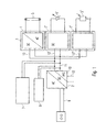
- a central unit comprising, for example, a rectifier 2 and optionally also a power factor correction circuit (PFC) 10, is jointly provided for a plurality of lamp operating devices 1, 1 ', 1 "
- the central unit 2, 10 can also be spatially separated from the operating devices and, for example, be arranged centrally for a room, a floor or even a building in a control cabinet, etc.
- the various light-emitting devices operating devices 1, 1 ', 1 a variety of light sources, such as a gas discharge lamp 5, light emitting diodes 5', etc. Actuate the bulbs themselves can be operated with DC or AC voltage, wherein in the latter case, an inverter is provided in the associated operating device.
- a light sensor 5 or a motion detector (not shown) may be connected to a DC output circuit 11 of the central unit.
- the operating devices 1, 1', 1" are designed differently.
- the corresponding operating device 3 is, for example, as an electronic ballast (EVG) u.a. formed with an inverter.
- EDG electronic ballast
- the operating devices can also be referred to as "output converters".
- Fig. 1 shown schematically may be designed bus-like an output circuit 11, so that starting from this central common bus 11, the various operating devices 1, 1 ', 1 "are supplied via stubs 13, 13', 13".
- individual output circuits 12 may be provided for individual operating devices or jointly supplied groups of operating devices.
- This DC output circuit has the advantage of being less susceptible to parasitic effects than corresponding AC circuits.
- the central unit is provided for a plurality of operating devices in common, wherein the central unit is connected to the operating devices by means of at least one DC output circuit.
- At least one PFC 10 can supply an example, by means of a transformer or the like. Potential-separated output circuit.
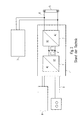
- a central control unit 31 is shown, which has a plurality of rectifier / PFC modules 36, which are arranged parallel to each other. Furthermore, a monitoring / control unit 393 is provided in the central rectifier unit 31.
- the central rectifier unit 31 is supplied with an AC voltage 35, in particular a mains voltage.
- the rectifier unit 31 has in the embodiment of Fig. 3 a plurality of DC output circuits, namely a high-voltage output circuit 39, a low-voltage output circuit 392 and a non-live terminal 34 which is connected to ground. Via the mentioned DC output circuits 39, 392 and 34, connected operating devices 32 for lighting means 33 can be supplied.
- ECGs electronic ballasts
- inverters DC / AC provided with which gas discharge lamps 33 can be controlled in a conventional manner.
- the low-voltage supply of logic components in the operating devices 32 such as provided by ASICS.
- the low-voltage output circuit 302 can also be used for signal transmission (for example in the form of a digital bus) from the central unit 31 to the connected operating devices 32 and possibly vice versa (bidirectional bus).
- the central rectifier unit 31 at least with respect to the DC output circuit 39, so a purely power-supplying DC output circuit without control function, the voltage U, the current I and / or the power P monitored by the monitoring / control circuit 393.
- the monitoring / control circuit 31 may have the function of a current limiting of the DC output circuit 39. It should be noted that in certain cases, the low-voltage output circuit 392 can serve for power supply. This is for example advantageously the case with the driving of LEDs. In this case, the voltage monitoring / control function, current and / or power can also be applied to these output circuits.
- the monitoring / control unit 393 may have a function that the DC output circuit is turned off if the voltage of the corresponding DC output circuit is below a predetermined value.
- a state change may indicate an error state of at least one connected operating device 32.
- state changes of the DC output circuit 39 or 392 defined in advance with the operating devices 32 can also be arranged in the sense of a signal feedback from an operating device 32 to the central unit 31.
- the change in state of an output circuit then represents a return channel of a signal bus.
- Such a change in state of the DC output circuit can be triggered selectively, for example, by a switchable load circuit in at least one of the resources.
- the central unit 31 can for example also put a DC output circuit (for example 39) in a standby state, in which the bus voltage is significantly lowered.
- a DC output circuit for example 39
- the lowered bus voltage can be chosen such that they are still sufficient to supply power to logic components (for example ASICs) in a connected operating device.
- a connected operating device 32 can be placed in a standby state in which the control logic is still actively supplied with power, the current bus voltage but not to control, for example, a connected gas discharge lamp 33 would be sufficient.
- the lowering of the bus voltage has the advantage that, in the event that, starting from a high bus voltage of, for example, 400 volts at the DC output circuit 39, a low-voltage supply voltage of, for example, 12 volts for logic components is obtained, which in the generation of low-voltage Voltage supply occurring (resistive) losses are significantly reduced.
- FIG. 4 Now, a particularly advantageous procedure will be explained, as it can be achieved with the present invention. Even if in Fig. 4 the central unit 41 is shown with only one rectifier / power factor correction module 46, it should be understood that here too the parallel modular structure is as shown in FIG Fig. 3 known, can be used. Also in the embodiment of Fig. 4 the current, voltage and / or power of the DC output circuit 44 for connected equipment 42 for connected lamps 43 is monitored and regulated. According to the invention, sudden load changes, in particular load jumps in the DC output circuit 44, ie the corresponding state change of the operating means 42 with connected lighting means 43, are not carried out until information (S1 in FIG Fig. 4 ) was transmitted to the central unit 41.
- parameters of the central processing unit 41 can be adjusted so that it adjusts to the expected future load in the DC output circuit 44.
- This setting can be used in the transmission of the embodiment of Fig. 3 according to the procedure Fig. 4 consist in that parallel-connected modules in the central unit 41 on or off.
- the values for the regulated parameter power, current or voltage can be set in advance in anticipation of a power jump in the DC output circuit.
- control signals for changing the state of a luminous means 43 are transmitted from a digital or analog bus 491 or from a pushbutton or switch command 492 to a powerline modulation unit 48.
- This modulation unit 48 thus modulates control signals to the DC output circuit 44.
- the powerline control command transmission of course, the connected equipment 42 has a powerline demodulator 493 to read over the bus 44 transmitted commands can.
- a user specifies a power change for a lighting means 43 by means of the switch or pushbutton 492 and / or via the digital or analog bus 491.
- the powerline modulator 48 generates a preliminary message to the central unit 41, which thus detects it by reading the powerline message from the DC output circuit 44.
- the parameter adaptation takes place in the central unit 41.
- the central unit 41 confirms to the powerline modulator 48 that the adaptation has been carried out. Only then does the powerline modulator 48 transmit the actual control command in a step S3 via the DC bus 44 or a separate control line to the operating means 42 to be controlled.
Abstract
Description
Die vorliegende Erfindung bezieht sich auf die Steuerung von Leuchtmittel-Betriebsgeräten ausgehend von einer zentralen Einheit.The present invention relates to the control of lamp operating devices from a central unit.
Dabei geht die Erfindung von einem in
Zusätzlich kann eine Notbeleuchtungssteuerung 7 vorgesehen sein.In addition, an emergency lighting control 7 may be provided.
Der Gleichrichter 2 in dem EVG 1 wird üblicherweise mit Wechselspannung 9, beispielsweise Netzspannung, versorgt.The
Gleichzeitig ist es bekannt, das EVG 1 über eine Digital- oder Analog-Bussteuerung 8 anzusteuern, um somit die Lampe 5 zu starten, zu dimmen oder auszuschalten. Festzuhalten ist, dass bei diesem Stand der Technik in jedem Lampenbetriebsgerät (EVG 1) ein eigener Gleichrichter 2 mit PFC-Schaltung vorgesehen ist. Eine derartige PFC-Schaltung verringert bekanntlich störende Oberwellen im Eingangsstrom. Andererseits stellen diese lokal in jedem EVG 1 vorgesehenen Wechselrichter mit PFC 2 einen beträchtlichen Kostenfaktor dar, der den Trend zu äußerst kostengünstig gefertigten EVGs stark eingrenzt.At the same time, it is known to control the electronic ballast 1 via a digital or
Ausgangspunkt und Aufgabe für die vorliegende Erfindung ist es dementsprechend, eine Ansteuerung für Leuchtmittel-Betriebsgeräte vorzuschlagen, die eine kostengünstigere Fertigung von Betriebsgeräten ermöglicht.Accordingly, the starting point and object of the present invention is to propose a drive for light source operating devices, which enables a more cost-effective production of operating devices.
Zentraler Punkt der Erfindung ist es dabei, dass die Einheit Gleichrichter/PFC nicht mehr lokal in jedem Betriebsgerät, sondern zentral für mehrere Betriebsgeräte vorgesehen ist. Die Verbindung zwischen dieser Zentrale und den einzelnen Betriebsgeräten erfolgt erfindungsgemäß über einen DC-Ausgangskreis.The central point of the invention is that the unit rectifier / PFC is no longer provided locally in each operating device, but centrally for several operating devices. The connection between this center and the individual operating devices is carried out according to the invention via a DC output circuit.
Gleichzeitig soll trotz der zentralen Ausgestaltung eine flexible und auf die Bedürfnisse der angeschlossenen Betriebsgeräte angepasste Versorgung ermöglicht werden.At the same time a flexible and adapted to the needs of the connected equipment supply is to be made possible despite the central design.
Die oben angeführte Aufgabe wird durch die Merkmale der unabhängigen Ansprüche gelöst. Die abhängigen Ansprüche bilden den zentralen Gedanken der Erfindung in besonders vorteilhafter Weise weiter.The above object is solved by the features of the independent claims. The dependent claims further form the central idea of the invention in a particularly advantageous manner.
Gemäß einem ersten Aspekt der vorliegenden Erfindung ist ein System zur zentralen Spannungsversorgung von Betriebsgeräten (Betriebsmitteln) für Leuchtmittel vorgesehen. Das System weist dabei eine zentrale Gleichrichter-Einheit mit einem eingangsseitigen Anschluß für Wechselspannung und wenigstens einem DC-Ausgangskreis auf. Weiterhin sind mehrere Betriebsgeräte für Leuchtmittel vorgesehen, die jeweils über den DC-Ausgangskreis mit Spannung versorgt werden. Dabei weist die zentrale Gleichrichter-Einheit eine Schaltung zur Regelung der Spannung, des Stroms und/oder der Leistung des Ausgangskreises auf.According to a first aspect of the present invention, a system for the central power supply of operating devices (operating means) for lighting means is provided. The system has a central rectifier unit with an input side connection for AC voltage and at least one DC output circuit. Furthermore, several operating devices are provided for lamps, which are each supplied via the DC output circuit with voltage. In this case, the central rectifier unit has a circuit for regulating the voltage, the current and / or the power of the output circuit.
Dabei kann die zentrale Gleichrichter-Einheit beispielsweise eine Schaltung zur Strombegrenzung des DC-Ausgangskreises aufweisen.In this case, the central rectifier unit, for example, have a circuit for limiting the current of the DC output circuit.
Die zentrale Gleichrichter-Einheit kann dazu ausgelegt sein, den DC-Ausgangskreis abzuschalten, sobald die (überwachte) Spannung des DC-Ausgangskreises einen vorbestimmten Wert unterschreitet.The central rectifier unit can be designed to switch off the DC output circuit as soon as the (monitored) voltage of the DC output circuit falls below a predetermined value.
Dazu kann die zentrale Gleichrichter-Einheit eine Überwachungseinheit für den Zustand des DC-Ausgangskreises aufweisen.For this purpose, the central rectifier unit may have a monitoring unit for the state of the DC output circuit.
Die Überwachungseinheit kann vorab definierte Änderungen des Zustands des DC-Ausgangskreises als Störungen der angeschlossenen Betriebsgeräte für Leuchtmittel und/oder als definierte Rückmeldungssignale eines Betriebsgeräts auswerten.The monitoring unit can evaluate previously defined changes in the state of the DC output circuit as failures of the connected operating devices for lighting devices and / or as defined feedback signals of a control gear.
Die zentrale Gleichrichter-Einheit kann eine Signal-Schnittstelle aufweisen, über die ihr vorab Informationen über zukünftige Laständerungen, insbesondere Lastsprünge im DC-Ausgangskreis zuführbar sind.The central rectifier unit can have a signal interface via which information about future load changes, in particular load jumps in the DC output circuit, can be fed to it in advance.
Als Antwort auf derartige Informationen bezüglich zukünftiger Laständerungen im DC-Ausgangskreis können Parameter der zentralen Gleichrichter-Einheit eingestellt werden.In response to such information regarding future load changes in the DC output circuit, parameters of the central rectifier unit may be adjusted.
Die zentrale Gleichrichter-Einheit kann beispielsweise in Form parallel geschalteter Module aufgebaut sein, wobei abhängig von den Informationen bezüglich zukünftiger Laständerungen Module zu- bzw. abgeschaltet werden.The central rectifier unit can be constructed, for example, in the form of modules connected in parallel, with modules being switched on or off depending on the information regarding future load changes.
Die zentrale Gleichrichter-Einheit kann den DC-Ausgangskreis in ein Standby-Zustand überführen, in dem die Busspannung verringert ist.The central rectifier unit may transition the DC output circuit to a standby state in which the bus voltage is reduced.
Dabei kann die verringerte Busspannung vorteilhafterweise derart gewählt sein, daß sie zur Versorgung von Logikbauteilen, wie beispielsweise ASICs, in einem Betriebsgerät für Leuchtmittel ausreicht.In this case, the reduced bus voltage can advantageously be chosen such that it is sufficient for the supply of logic components, such as ASICs, in a control gear for lighting.
Ergänzend kann die zentrale Gleichrichter-Einheit weiterhin eine Leistungsfaktor-Korrektureinheit aufweisen.In addition, the central rectifier unit may further comprise a power factor correction unit.
Gemäß einem weiteren Aspekt der vorliegenden Erfindung ist ein Verfahren zur zentralen Spannungsversorgung von Betriebsgeräten für Leuchtmittel vorgesehen. Dabei regelt eine zentrale Gleichrichter-Einheit die Spannung, den Strom und/oder die Leistung in einem DC-Ausgangskreis.According to a further aspect of the present invention, a method for the central power supply of operating devices for lighting means is provided. A central rectifier unit regulates the voltage, the current and / or the power in a DC output circuit.
Gemäß einem noch weiteren Aspekt der vorliegenden Erfindung ist ein Verfahren zur zentralen Spannungsversorgung von Betriebsgeräten für Leuchtmittel vorgesehen, wobei einer zentralen Gleichrichter-Einheit vorab Informationen über zukünftige Laständerungen, insbesondere Lastsprünge im DC-Ausgangskreis zugeführt werden, so daß sich die zentrale Gleichrichter-Einheit vorab auf derartige zu erwartende Laständerungen einstellen kann.According to yet another aspect of the present invention, a method for central power supply of operating devices for lighting means is provided, wherein a central rectifier unit be supplied in advance information about future load changes, in particular load jumps in the DC output circuit, so that the central rectifier unit in advance can adjust to such expected load changes.
Weitere Merkmale, Vorteile und Eigenschaften der vorliegenden Erfindung sollen nunmehr unter Bezugnahme auf die Figuren der beigefügten Zeichnungen sowie die folgende detaillierte Beschreibung eines Ausführungsbeispieles näher erläutert werden.
-
Fig. 1 zeigt eine schematische Ansicht eines erfindungsgemäßen Steuersystems für Leuchtmittel-Betriebsgeräte mit zentraler Gleichrichter/PFC-Einheit und DC-Ausgangskreis, -
Fig. 2 zeigt eine aus dem Stand der Technik bekannte Betriebsmittel-Ausgestaltung für Gasentladungslampen, -
Fig. 3 zeigt einen ersten schematischen Schaltplan eines Ausführungsbeispiels der vorliegenden Erfindung, und -
Fig. 4 zeigt einen schematischen Schaltplan zur Erläuterung des Ablaufs bei einer Vorab-Information einer zentralen Gleichrichter-Einheit bezüglich zukünftiger zu erwartender Lastsprünge im DC-Ausgangskreis.
-
Fig. 1 shows a schematic view of a control system according to the invention for light-emitting devices with central rectifier / PFC unit and DC output circuit, -
Fig. 2 shows one known from the prior art Equipment design for gas discharge lamps, -
Fig. 3 shows a first schematic circuit diagram of an embodiment of the present invention, and -
Fig. 4 shows a schematic circuit diagram for explaining the sequence in advance information of a central rectifier unit with respect to future expected load jumps in the DC output circuit.
Wie in
Wie in
Weiterhin können an einen DC-Ausgangskreis 11 der Zentraleinheit auch andere (bspw. passive) lichttechnische oder gebäudetechnische Einrichtungen, wie beispielsweise ein Lichtsensor 5" oder ein Bewegungsmelder (nicht dargestellt) angeschlossen sein.Furthermore, other (eg passive) lighting or building services equipment, such as a light sensor 5 "or a motion detector (not shown) may be connected to a
Je nach Natur der angeschlossenen Leuchtmittel 5, 5' bzw. Sensoren 5" sind die Betriebsgeräte 1, 1', 1" unterschiedlich ausgebildet. Für den Fall, dass eine Gasentladungslampe 5 angesteuert werden soll, ist das entsprechende Betriebsgerät 3 bspw. als elektronisches Vorschaltgerät (EVG) u.a. mit einem Wechselrichter ausgebildet. Die Betriebsgeräte können in diesem Fall auch als "Ausgangs-Konverter" bezeichnet werden.Depending on the nature of the connected lamps 5, 5 'or sensors 5 ", the operating devices 1, 1', 1" are designed differently. In the event that a gas discharge lamp 5 is to be controlled, the
Die Spannungsversorgung der Betriebsgeräte und Leuchtmittel und optional auch die uni- oder bidirektionale Kommunikation zwischen der Zentraleinheit und den lokalen Betriebsgeräten 1, 1', 1" erfolgt über wenigstens einen DC-Ausgangskreis 11, 12. Wie in
Dieser DC-Ausgangskreis hat den Vorteil, dass er im Vergleich zu entsprechenden AC-Kreisen weniger anfällig gegenüber parasitären Effekten ist.This DC output circuit has the advantage of being less susceptible to parasitic effects than corresponding AC circuits.
Festzuhalten ist, dass gemäß der vorliegenden Erfindung die Zentraleinheit für mehrere Betriebsgeräte gemeinsam vorgesehen ist, wobei die Zentraleinheit mit den Betriebsgeräten mittels wenigstens einem DC-Ausgangskreis verbunden ist.It should be noted that according to the present invention, the central unit is provided for a plurality of operating devices in common, wherein the central unit is connected to the operating devices by means of at least one DC output circuit.
Wenigstens ein PFC 10 kann dabei einen bspw. Mittels eines Trafos oder dgl. potentialgetrennten Ausgangskreis versorgen. Eine besondere Ausgestaltung eines derartigen Systems der zentralen Spannungsversorgung von Betriebsgeräten für Leuchtmittel soll nunmehr bezugnehmend auf
Vergleichbar zu dem Ausführungsbeispiel von
Mit dem Mittelspannungs-Ausgangskreis 392 kann beispielsweise die Niederspannungs-Versorgung von Logikbauteilen in den Betriebsgeräten 32, wie beispielsweise von ASICS bereitgestellt werden. Alternativ oder zusätzlich kann der Niederspannungs-Ausgangskreis 302 auch zur Signalübermittlung (beispielsweise in Form eines digitalen Busses) von der Zentraleinheit 31 zur den angeschlossenen Betriebsgeräten 32 und ggf. auch umgekehrt (bidirektionaler Bus) verwendet werden.With the medium-
Da bekanntlich das Ausschalten über eine DC-Leitung mit hoher Spannung (hier beispielsweise DC-Ausgangskreis 39) zu Problemen bezüglich der Bildung einer Funkenstrecke (Lichtbogen) führen kann, kann vorteilhafterweise auch ein Ausschalten der an die Betriebsgeräte 32 angeschlossenen Leuchtmittel 33 durch einen einfachen Schalter 391 im Niederspannungs-Ausgangskreis 392 erreicht werden. Ein Öffnen des Schalters 391 kann entweder als digitales Signal durch lokale Steuereinheiten in den Betriebsgeräten 32 ausgewertet werden. Alternativ kann durch Öffnen des Schalters 391 eine Spannungsversorgung für Logikbauteile in den Betriebsgeräten 32 abgeschaltet werden, so daß die angeschlossenen Leuchtmittel 33 indirekt abgeschaltet werden.As is known switching off via a DC line with high voltage (here, for example, DC output circuit 39) Problems relating to the formation of a spark gap (arc) can advantageously be achieved by switching off the connected to the operating
Es ist vorgesehen, daß die zentrale Gleichrichtereinheit 31 zumindest bezüglich des DC-Ausgangskreises 39, also einem rein leistungsversorgenden DC-Ausgangskreis ohne Steuerfunktion, die Spannung U, den Strom I und/oder die Leistung P mittels der Überwachung-/Steuerschaltung 393 überwacht.It is envisaged that the
Die Überwachungs-/Steuerschaltung 31 kann dabei die Funktion einer Strombegrenzung des DC-Ausgangskreises 39 aufweisen. Es sei anzumerken, daß in bestimmten Fällen auch der Niederspannungs-Ausgangskreis 392 zur Leistungsversorgung dienen kann. Dies ist beispielsweise vorteilhafterweise bei der Ansteuerung von LEDs der Fall. In diesem Fall kann die Überwachung-/Regelungsfunktion der Spannung, des Stroms und/oder der Leistung auch auf diesen Ausgangskreisen Anwendung finden.The monitoring /
Die Überwachungs-/Steuereinheit 393 kann eine Funktion aufweisen, daß der DC-Ausgangskreis abgeschaltet wird, falls die Spannung des entsprechenden DC-Ausgangskreises einen vorbestimmten Wert unterschreitet.The monitoring /
Durch die kontinuierliche oder abschnittsweise Überwachung des Zustands des DC-Ausgangskreises 39 und ggf. auch 392 können verschiedene Rückschlüsse aus einer Zustandsänderung des entsprechenden DC-Ausgangskreises geschlossen werden. Beispielsweise kann eine Zustandsänderung auf einen Fehlerzustand wenigstens eines angeschlossenen Betriebsgeräts 32 schließen lassen. Alternativ oder zusätzlich können vorab auch mit den Betriebsgeräten 32 definierte Zustandsänderungen des DC-Ausgangskreises 39 bzw. 392 im Sinne einer Signal-Rückmeldung von einem Betriebsgerät 32 zu der Zentraleinheit 31 verabredet sein. Somit stellt die Zustandsänderung eines Ausgangskreises dann einen Rückkanal eines Signalbusses dar. Eine derartige Zustandsänderung des DC-Ausgangskreises kann bspw. durch einen schaltbaren Lastkreis in wenigstens einem der Betriebsmittel gezielt ausgelöst werden.By the continuous or sectional monitoring of the state of the
Da wie gesagt Strom, Spannung und/oder Leistung der DC-Ausgangskreise überwacht und geregelt sein können, kann die Zentraleinheit 31 beispielsweise auch einen DC-Ausgangskreis (beispielsweise 39) in einen Standby-Zustand versetzen, in dem die Busspannung deutlich abgesenkt ist. Dies hat den Vorteil, daß die abgesenkte Busspannung derart gewählt sein kann, daß sie immer noch zur Leistungsversorgung von Logikbauteilen (beispielsweise ASICs) in einem angeschlossenen Betriebsgerät ausreichen. Somit kann ein angeschlossenes Betriebsgerät 32 in einen Standby-Zustand versetzt werden, in dem die Steuerlogik noch aktiv mit Spannung versorgt ist, die aktuelle Busspannung aber nicht zur Ansteuerung beispielsweise einer angeschlossenen Gasentladungslampe 33 ausreichen würde.As mentioned, since current, voltage and / or power of the DC output circuits can be monitored and regulated, the
Die Absenkung der Busspannung hat andererseits den Vorteil, daß für den Fall, daß ausgehend von einer hohen Busspannung von beispielsweise 400 Volt bei dem DC-Ausgangskreis 39 eine Niedervolt-Versorgungsspannung von beispielsweise 12 Volt für Logikbauteile gewonnen wird, die bei der Erzeugung der Niedervolt-Spannungsversorgung auftretenden (ohmschen) Verluste deutlich reduziert werden.The lowering of the bus voltage on the other hand has the advantage that, in the event that, starting from a high bus voltage of, for example, 400 volts at the
Bezugnehmend auf
Wenn also eine Leistungsänderung im DC-Ausgangskreis 44 erfolgen soll, wird sichergestellt, daß die Zentraleinheit 41 auf diese Leistungsänderung vorbereitet ist. Dies kann dadurch geschehen, daß beispielsweise nach Übermittlung der Vorabinformation S1 an die Zentraleinheit 41 eine definierte Zeitspanne ablaufen muß, bevor das eigentliche Ansteuersignal S3 an die Betriebsmittel 42 für die Leuchtmittel 43 übermittelt wird. Andererseits kann aber auch vorgesehen sein, daß diese Ansteuerbefehle S3 erst dann übermittelt werden, wenn eine definierte Rückmeldung von der Zentraleinheit 41 erfolgte.Thus, when a power change is to take place in the
In dem Ausführungsbeispiel von
In dem Ablauf gemäß
Claims (17)
wobei zusätzlich der Niederspannungs-Ausgangskreis (392) zur Signalübermittlung von der zentralen Gleichrichter-Einheit (31) zu den Betriebsgeräten (32) verwendet wird.System according to claim 1,
in addition, the low-voltage output circuit (392) is used for signal transmission from the central rectifier unit (31) to the operating devices (32).
wobei der Niederspannungs-Ausgangskreis (392) eine Niederspannungs-Versorgung von Logikbauteilen in den Betriebsgeräten (32), wie bspw. ASICS, bereitstellt.System according to claim 3,
wherein the low voltage output circuit (392) provides a low voltage supply of logic components in the operating devices (32), such as ASICS.
bei dem die Signalübermittlung in Form eines digitalen Busses erfolgt.System according to claim 2 or 3,
in which the signal transmission takes place in the form of a digital bus.
bei dem die Signalübermittlung als bidirektionaler Bus verwendet wird.System according to claim 5,
in which the signal transmission is used as a bidirectional bus.
dadurch gekennzeichnet,
dass die zentrale Gleichrichtereinheit (31) den DC-Ausgangskreis in einen Standby-Zustand mit verringerter Busspannung überführen kann.System according to one of the preceding claims,
characterized,
in that the central rectifier unit (31) can convert the DC output circuit into a standby state with a reduced bus voltage.
dadurch gekennzeichnet,
dass die verringerte Busspannung derart gewählt ist, dass sie zur Versorgung von Logikbauteilen in einem Betriebsgerät (32) für Leuchtmittel (33) ausreicht.System according to claim 7,
characterized,
in that the reduced bus voltage is chosen such that it is sufficient to supply logic components in a lighting device (32) for operating means (32).
bei dem die Überwachungseinheit (393) vorab definierte Änderungen des Zustands des DC-Ausgangskreises (39, 392) als Störungen der angeschlossenen Betriebsgeräte (32) für Leuchtmittel (33) wertet und ein Störsignal erzeugt.System according to claim 13,
in which the monitoring unit (393) evaluates previously defined changes in the state of the DC output circuit (39, 392) as failures of the connected operating devices (32) for lighting means (33) and generates an interference signal.
bei dem die Überwachungseinheit (393) vorab definierte Änderungen des Zustands des DC-Ausgangskreises als definierte Rückmeldung eines Betriebsgeräts (32) für Leuchtmittel (33) über den DC-Ausgangskreis auswertet.System according to claim 13,
in which the monitoring unit (393) predefined changes in the state of the DC output circuit as a defined feedback of a control device (32) for Bulb (33) evaluates via the DC output circuit.
bei dem die zentrale Gleichrichtereinheit (31) eine Signal-Schnittstelle aufweist, über die ihr vorab Informationen über zukünftige Laständerungen, insbesondere Lastsprünge im DC-Ausgangskreis (39, 393) zuführbar sind.System according to one of the preceding claims,
in which the central rectifier unit (31) has a signal interface via which information about future load changes, in particular load jumps, in the DC output circuit (39, 393) can be fed beforehand.
Applications Claiming Priority (2)
| Application Number | Priority Date | Filing Date | Title |
|---|---|---|---|
| DE102004002027.2A DE102004002027B4 (en) | 2004-01-14 | 2004-01-14 | Central PFC with DC output circuit control |
| EP04028277A EP1555858B1 (en) | 2004-01-14 | 2004-11-29 | Central power supply for lamp operation devices containing a central PFC/rectification device |
Related Parent Applications (2)
| Application Number | Title | Priority Date | Filing Date |
|---|---|---|---|
| EP04028277A Division EP1555858B1 (en) | 2004-01-14 | 2004-11-29 | Central power supply for lamp operation devices containing a central PFC/rectification device |
| EP04028277.4 Division | 2004-11-29 |
Publications (3)
| Publication Number | Publication Date |
|---|---|
| EP2365737A2 true EP2365737A2 (en) | 2011-09-14 |
| EP2365737A3 EP2365737A3 (en) | 2013-12-11 |
| EP2365737B1 EP2365737B1 (en) | 2019-01-30 |
Family
ID=34609553
Family Applications (2)
| Application Number | Title | Priority Date | Filing Date |
|---|---|---|---|
| EP11162425.0A Active EP2365737B1 (en) | 2004-01-14 | 2004-11-29 | Central PFC with DC output circuit regulation |
| EP04028277A Active EP1555858B1 (en) | 2004-01-14 | 2004-11-29 | Central power supply for lamp operation devices containing a central PFC/rectification device |
Family Applications After (1)
| Application Number | Title | Priority Date | Filing Date |
|---|---|---|---|
| EP04028277A Active EP1555858B1 (en) | 2004-01-14 | 2004-11-29 | Central power supply for lamp operation devices containing a central PFC/rectification device |
Country Status (4)
| Country | Link |
|---|---|
| EP (2) | EP2365737B1 (en) |
| AT (1) | ATE521214T1 (en) |
| DE (1) | DE102004002027B4 (en) |
| PL (1) | PL1555858T3 (en) |
Families Citing this family (6)
| Publication number | Priority date | Publication date | Assignee | Title |
|---|---|---|---|---|
| AT14601U1 (en) * | 2013-04-30 | 2016-02-15 | Tridonic Gmbh & Co Kg | effect lighting |
| EP3058794B1 (en) | 2013-10-15 | 2018-08-29 | Philips Lighting Holding B.V. | Drive unit for a lighting element and operating method therefor |
| AT14100U1 (en) * | 2013-10-16 | 2015-04-15 | Tridonic Gmbh & Co Kg | Method and apparatus for communication in a lighting system |
| EP2925094B1 (en) | 2014-03-25 | 2019-01-30 | Tridonic GmbH & Co KG | Lighting system and method for operating a lighting system using power consumption for information transmission |
| DE102015005240A1 (en) * | 2015-04-26 | 2016-10-27 | Tilman Röder | Method of installing a power distribution system in the range of low voltage below 25 volts AC or 60 volts DC, using at least one power supply unit to power two or more possible power consumers, and a corresponding power distribution system and associated apparatus |
| DE102015117206A1 (en) * | 2015-10-08 | 2017-04-13 | I.S.T. Innovative Sewer Technologies Gmbh | Curing device with a UV light-generating lamp |
Family Cites Families (12)
| Publication number | Priority date | Publication date | Assignee | Title |
|---|---|---|---|---|
| DE3925899A1 (en) * | 1989-08-04 | 1991-02-07 | Zumtobel Ag | ELECTRONIC CONTROLLER FOR GAS DISCHARGE LAMPS |
| WO1992017993A1 (en) * | 1991-03-28 | 1992-10-15 | Thien Siung Yang | Improvements in lamp ballasts |
| WO1994027419A1 (en) * | 1993-05-13 | 1994-11-24 | Etta Industries, Inc. | System and method for distributing power to gas discharge lamps |
| DE19502772C2 (en) * | 1995-01-30 | 2002-02-28 | Walter Holzer | Electronic ballast for fluorescent lamps |
| EP0903966B1 (en) * | 1997-09-18 | 2003-04-16 | CEAG Sicherheitstechnik GmbH | Lighting system |
| US6480043B2 (en) * | 1999-05-24 | 2002-11-12 | Semiconductor Components Industries Llc | Circuit and method for protecting a switching power supply from a fault condition |
| EP1771046B1 (en) * | 2000-09-15 | 2016-03-16 | Tridonic GmbH & Co KG | Electronic ballast with a digital control unit |
| IT1316561B1 (en) * | 2000-12-28 | 2003-04-22 | Setech S R L | FEEDING DEVICE FOR COLD CATHODE LAMPS. |
| DE10106438A1 (en) * | 2001-02-09 | 2002-08-14 | Patent Treuhand Ges Fuer Elektrische Gluehlampen Mbh | Ballast for operating electric lamps |
| EP1244337A1 (en) * | 2001-03-20 | 2002-09-25 | MAGNETEK S.p.A. | Lighting system with an electrified line and a plurality of lighting fixtures connected to it |
| US6534933B2 (en) * | 2001-05-15 | 2003-03-18 | Koninklijke Philips Electronics N.V. | High power factor electronic ballast with load dependent bus voltage regulation |
| US6621238B2 (en) * | 2002-01-25 | 2003-09-16 | General Electric Company | Power factor correction circuit with faster bus charging rate during startup |
-
2004
- 2004-01-14 DE DE102004002027.2A patent/DE102004002027B4/en not_active Expired - Fee Related
- 2004-11-29 EP EP11162425.0A patent/EP2365737B1/en active Active
- 2004-11-29 PL PL04028277T patent/PL1555858T3/en unknown
- 2004-11-29 AT AT04028277T patent/ATE521214T1/en active
- 2004-11-29 EP EP04028277A patent/EP1555858B1/en active Active
Non-Patent Citations (1)
| Title |
|---|
| None |
Also Published As
| Publication number | Publication date |
|---|---|
| PL1555858T3 (en) | 2012-01-31 |
| DE102004002027A1 (en) | 2005-08-04 |
| EP2365737A3 (en) | 2013-12-11 |
| EP1555858B1 (en) | 2011-08-17 |
| EP1555858A2 (en) | 2005-07-20 |
| EP1555858A3 (en) | 2005-08-31 |
| EP2365737B1 (en) | 2019-01-30 |
| ATE521214T1 (en) | 2011-09-15 |
| DE102004002027B4 (en) | 2020-03-26 |
Similar Documents
| Publication | Publication Date | Title |
|---|---|---|
| EP1555859B1 (en) | Control of lighting devices over a modulated DC bus | |
| DE102009051968B4 (en) | Method for transmitting control information from a control unit to a lamp unit, a suitable lighting system, and lamp unit | |
| DE102005018775A1 (en) | Electronic ballast for e.g. fluorescent lamp, has microcontroller assigned to intermediate circuit voltage regulator, where external instructions are applied to microcontroller, and properties of regulator depend on external instructions | |
| DE202008002883U1 (en) | Circuit for controlling at least one light unit and light | |
| EP2604097B1 (en) | Modulation of a pfc during dc operation | |
| EP1555860B1 (en) | DC-fed driving modules for light sources | |
| EP2365737B1 (en) | Central PFC with DC output circuit regulation | |
| EP1583402B1 (en) | Control of lighting devices with a central AC/DC cascaded converter | |
| EP1555861B1 (en) | Control of lighting apparatusses through switching modulation on a DC-bus | |
| EP2278861B1 (en) | Central power supply having several DC output circuits | |
| EP2591640B1 (en) | Control of operational parameters of operational devices for led's | |
| WO2011041817A2 (en) | Method for controlling light control devices | |
| EP2425683B1 (en) | Interface for a lighting system | |
| DE102006001256A1 (en) | Method for operating a light source with the aid of a lamp operating device and lamp operating device therefor | |
| WO2011106814A2 (en) | Operating device for light-emitting means | |
| DE102004012216B4 (en) | Control of illuminant control gear via a switchable DC bus | |
| DE102008035219A1 (en) | Control circuit for use in electronic ballast of illumination system, has communication interface receiving hardware instructions for adjustment of parameters of circuit, and storage register storing hardware instructions | |
| DE102017126742A1 (en) | Circuit arrangement with an operating circuit and method for programming or updating at least one operating characteristic of the operating circuit | |
| DE102018205756A1 (en) | DEVICE, SYSTEM AND METHOD FOR CONTROLLING LIGHTING DEVICES | |
| DE102014111711A1 (en) | Control of power consumption of outdoor electrical consumers |
Legal Events
| Date | Code | Title | Description |
|---|---|---|---|
| PUAI | Public reference made under article 153(3) epc to a published international application that has entered the european phase |
Free format text: ORIGINAL CODE: 0009012 |
|
| AC | Divisional application: reference to earlier application |
Ref document number: 1555858 Country of ref document: EP Kind code of ref document: P |
|
| AK | Designated contracting states |
Kind code of ref document: A2 Designated state(s): AT BE BG CH CY CZ DE DK EE ES FI FR GB GR HU IE IS IT LI LU MC NL PL PT RO SE SI SK TR |
|
| RIC1 | Information provided on ipc code assigned before grant |
Ipc: H05B 41/24 20060101AFI20130708BHEP Ipc: H05B 41/285 20060101ALI20130708BHEP Ipc: H05B 41/298 20060101ALI20130708BHEP |
|
| RIC1 | Information provided on ipc code assigned before grant |
Ipc: H05B 41/285 20060101ALI20130912BHEP Ipc: H05B 41/298 20060101ALI20130912BHEP Ipc: H05B 41/24 20060101AFI20130912BHEP |
|
| RIC1 | Information provided on ipc code assigned before grant |
Ipc: H05B 41/24 20060101AFI20130919BHEP Ipc: H05B 41/298 20060101ALI20130919BHEP Ipc: H05B 41/285 20060101ALI20130919BHEP |
|
| PUAL | Search report despatched |
Free format text: ORIGINAL CODE: 0009013 |
|
| AK | Designated contracting states |
Kind code of ref document: A3 Designated state(s): AT BE BG CH CY CZ DE DK EE ES FI FR GB GR HU IE IS IT LI LU MC NL PL PT RO SE SI SK TR |
|
| RIC1 | Information provided on ipc code assigned before grant |
Ipc: H05B 41/24 20060101AFI20131107BHEP Ipc: H05B 41/298 20060101ALI20131107BHEP Ipc: H05B 41/285 20060101ALI20131107BHEP |
|
| 17P | Request for examination filed |
Effective date: 20140602 |
|
| RBV | Designated contracting states (corrected) |
Designated state(s): AT BE BG CH CY CZ DE DK EE ES FI FR GB GR HU IE IS IT LI LU MC NL PL PT RO SE SI SK TR |
|
| STAA | Information on the status of an ep patent application or granted ep patent |
Free format text: STATUS: EXAMINATION IS IN PROGRESS |
|
| 17Q | First examination report despatched |
Effective date: 20180104 |
|
| GRAP | Despatch of communication of intention to grant a patent |
Free format text: ORIGINAL CODE: EPIDOSNIGR1 |
|
| STAA | Information on the status of an ep patent application or granted ep patent |
Free format text: STATUS: GRANT OF PATENT IS INTENDED |
|
| INTG | Intention to grant announced |
Effective date: 20180419 |
|
| GRAS | Grant fee paid |
Free format text: ORIGINAL CODE: EPIDOSNIGR3 |
|
| GRAJ | Information related to disapproval of communication of intention to grant by the applicant or resumption of examination proceedings by the epo deleted |
Free format text: ORIGINAL CODE: EPIDOSDIGR1 |
|
| GRAL | Information related to payment of fee for publishing/printing deleted |
Free format text: ORIGINAL CODE: EPIDOSDIGR3 |
|
| STAA | Information on the status of an ep patent application or granted ep patent |
Free format text: STATUS: EXAMINATION IS IN PROGRESS |
|
| INTC | Intention to grant announced (deleted) | ||
| GRAP | Despatch of communication of intention to grant a patent |
Free format text: ORIGINAL CODE: EPIDOSNIGR1 |
|
| STAA | Information on the status of an ep patent application or granted ep patent |
Free format text: STATUS: GRANT OF PATENT IS INTENDED |
|
| GRAA | (expected) grant |
Free format text: ORIGINAL CODE: 0009210 |
|
| STAA | Information on the status of an ep patent application or granted ep patent |
Free format text: STATUS: THE PATENT HAS BEEN GRANTED |
|
| INTG | Intention to grant announced |
Effective date: 20181205 |
|
| AC | Divisional application: reference to earlier application |
Ref document number: 1555858 Country of ref document: EP Kind code of ref document: P |
|
| AK | Designated contracting states |
Kind code of ref document: B1 Designated state(s): AT BE BG CH CY CZ DE DK EE ES FI FR GB GR HU IE IS IT LI LU MC NL PL PT RO SE SI SK TR |
|
| REG | Reference to a national code |
Ref country code: GB Ref legal event code: FG4D Free format text: NOT ENGLISH |
|
| REG | Reference to a national code |
Ref country code: CH Ref legal event code: EP |
|
| REG | Reference to a national code |
Ref country code: AT Ref legal event code: REF Ref document number: 1094242 Country of ref document: AT Kind code of ref document: T Effective date: 20190215 |
|
| REG | Reference to a national code |
Ref country code: IE Ref legal event code: FG4D Free format text: LANGUAGE OF EP DOCUMENT: GERMAN |
|
| REG | Reference to a national code |
Ref country code: DE Ref legal event code: R096 Ref document number: 502004015766 Country of ref document: DE |
|
| REG | Reference to a national code |
Ref country code: NL Ref legal event code: MP Effective date: 20190130 |
|
| PG25 | Lapsed in a contracting state [announced via postgrant information from national office to epo] |
Ref country code: PT Free format text: LAPSE BECAUSE OF FAILURE TO SUBMIT A TRANSLATION OF THE DESCRIPTION OR TO PAY THE FEE WITHIN THE PRESCRIBED TIME-LIMIT Effective date: 20190530 Ref country code: NL Free format text: LAPSE BECAUSE OF FAILURE TO SUBMIT A TRANSLATION OF THE DESCRIPTION OR TO PAY THE FEE WITHIN THE PRESCRIBED TIME-LIMIT Effective date: 20190130 Ref country code: ES Free format text: LAPSE BECAUSE OF FAILURE TO SUBMIT A TRANSLATION OF THE DESCRIPTION OR TO PAY THE FEE WITHIN THE PRESCRIBED TIME-LIMIT Effective date: 20190130 Ref country code: FI Free format text: LAPSE BECAUSE OF FAILURE TO SUBMIT A TRANSLATION OF THE DESCRIPTION OR TO PAY THE FEE WITHIN THE PRESCRIBED TIME-LIMIT Effective date: 20190130 Ref country code: PL Free format text: LAPSE BECAUSE OF FAILURE TO SUBMIT A TRANSLATION OF THE DESCRIPTION OR TO PAY THE FEE WITHIN THE PRESCRIBED TIME-LIMIT Effective date: 20190130 Ref country code: SE Free format text: LAPSE BECAUSE OF FAILURE TO SUBMIT A TRANSLATION OF THE DESCRIPTION OR TO PAY THE FEE WITHIN THE PRESCRIBED TIME-LIMIT Effective date: 20190130 |
|
| PG25 | Lapsed in a contracting state [announced via postgrant information from national office to epo] |
Ref country code: BG Free format text: LAPSE BECAUSE OF FAILURE TO SUBMIT A TRANSLATION OF THE DESCRIPTION OR TO PAY THE FEE WITHIN THE PRESCRIBED TIME-LIMIT Effective date: 20190430 Ref country code: IS Free format text: LAPSE BECAUSE OF FAILURE TO SUBMIT A TRANSLATION OF THE DESCRIPTION OR TO PAY THE FEE WITHIN THE PRESCRIBED TIME-LIMIT Effective date: 20190530 Ref country code: GR Free format text: LAPSE BECAUSE OF FAILURE TO SUBMIT A TRANSLATION OF THE DESCRIPTION OR TO PAY THE FEE WITHIN THE PRESCRIBED TIME-LIMIT Effective date: 20190501 |
|
| REG | Reference to a national code |
Ref country code: DE Ref legal event code: R084 Ref document number: 502004015766 Country of ref document: DE |
|
| PG25 | Lapsed in a contracting state [announced via postgrant information from national office to epo] |
Ref country code: CZ Free format text: LAPSE BECAUSE OF FAILURE TO SUBMIT A TRANSLATION OF THE DESCRIPTION OR TO PAY THE FEE WITHIN THE PRESCRIBED TIME-LIMIT Effective date: 20190130 Ref country code: RO Free format text: LAPSE BECAUSE OF FAILURE TO SUBMIT A TRANSLATION OF THE DESCRIPTION OR TO PAY THE FEE WITHIN THE PRESCRIBED TIME-LIMIT Effective date: 20190130 Ref country code: IT Free format text: LAPSE BECAUSE OF FAILURE TO SUBMIT A TRANSLATION OF THE DESCRIPTION OR TO PAY THE FEE WITHIN THE PRESCRIBED TIME-LIMIT Effective date: 20190130 Ref country code: SK Free format text: LAPSE BECAUSE OF FAILURE TO SUBMIT A TRANSLATION OF THE DESCRIPTION OR TO PAY THE FEE WITHIN THE PRESCRIBED TIME-LIMIT Effective date: 20190130 Ref country code: DK Free format text: LAPSE BECAUSE OF FAILURE TO SUBMIT A TRANSLATION OF THE DESCRIPTION OR TO PAY THE FEE WITHIN THE PRESCRIBED TIME-LIMIT Effective date: 20190130 Ref country code: EE Free format text: LAPSE BECAUSE OF FAILURE TO SUBMIT A TRANSLATION OF THE DESCRIPTION OR TO PAY THE FEE WITHIN THE PRESCRIBED TIME-LIMIT Effective date: 20190130 |
|
| REG | Reference to a national code |
Ref country code: DE Ref legal event code: R097 Ref document number: 502004015766 Country of ref document: DE |
|
| PLBE | No opposition filed within time limit |
Free format text: ORIGINAL CODE: 0009261 |
|
| STAA | Information on the status of an ep patent application or granted ep patent |
Free format text: STATUS: NO OPPOSITION FILED WITHIN TIME LIMIT |
|
| 26N | No opposition filed |
Effective date: 20191031 |
|
| PG25 | Lapsed in a contracting state [announced via postgrant information from national office to epo] |
Ref country code: SI Free format text: LAPSE BECAUSE OF FAILURE TO SUBMIT A TRANSLATION OF THE DESCRIPTION OR TO PAY THE FEE WITHIN THE PRESCRIBED TIME-LIMIT Effective date: 20190130 |
|
| PGFP | Annual fee paid to national office [announced via postgrant information from national office to epo] |
Ref country code: FR Payment date: 20191126 Year of fee payment: 16 |
|
| PG25 | Lapsed in a contracting state [announced via postgrant information from national office to epo] |
Ref country code: TR Free format text: LAPSE BECAUSE OF FAILURE TO SUBMIT A TRANSLATION OF THE DESCRIPTION OR TO PAY THE FEE WITHIN THE PRESCRIBED TIME-LIMIT Effective date: 20190130 |
|
| PGFP | Annual fee paid to national office [announced via postgrant information from national office to epo] |
Ref country code: AT Payment date: 20191121 Year of fee payment: 16 |
|
| REG | Reference to a national code |
Ref country code: CH Ref legal event code: PL |
|
| PG25 | Lapsed in a contracting state [announced via postgrant information from national office to epo] |
Ref country code: MC Free format text: LAPSE BECAUSE OF FAILURE TO SUBMIT A TRANSLATION OF THE DESCRIPTION OR TO PAY THE FEE WITHIN THE PRESCRIBED TIME-LIMIT Effective date: 20190130 Ref country code: CH Free format text: LAPSE BECAUSE OF NON-PAYMENT OF DUE FEES Effective date: 20191130 Ref country code: LI Free format text: LAPSE BECAUSE OF NON-PAYMENT OF DUE FEES Effective date: 20191130 Ref country code: LU Free format text: LAPSE BECAUSE OF NON-PAYMENT OF DUE FEES Effective date: 20191129 |
|
| REG | Reference to a national code |
Ref country code: BE Ref legal event code: MM Effective date: 20191130 |
|
| PG25 | Lapsed in a contracting state [announced via postgrant information from national office to epo] |
Ref country code: IE Free format text: LAPSE BECAUSE OF NON-PAYMENT OF DUE FEES Effective date: 20191129 |
|
| PG25 | Lapsed in a contracting state [announced via postgrant information from national office to epo] |
Ref country code: BE Free format text: LAPSE BECAUSE OF NON-PAYMENT OF DUE FEES Effective date: 20191130 |
|
| PG25 | Lapsed in a contracting state [announced via postgrant information from national office to epo] |
Ref country code: CY Free format text: LAPSE BECAUSE OF FAILURE TO SUBMIT A TRANSLATION OF THE DESCRIPTION OR TO PAY THE FEE WITHIN THE PRESCRIBED TIME-LIMIT Effective date: 20190130 |
|
| REG | Reference to a national code |
Ref country code: AT Ref legal event code: MM01 Ref document number: 1094242 Country of ref document: AT Kind code of ref document: T Effective date: 20201129 |
|
| PG25 | Lapsed in a contracting state [announced via postgrant information from national office to epo] |
Ref country code: HU Free format text: LAPSE BECAUSE OF FAILURE TO SUBMIT A TRANSLATION OF THE DESCRIPTION OR TO PAY THE FEE WITHIN THE PRESCRIBED TIME-LIMIT; INVALID AB INITIO Effective date: 20041129 |
|
| PG25 | Lapsed in a contracting state [announced via postgrant information from national office to epo] |
Ref country code: AT Free format text: LAPSE BECAUSE OF NON-PAYMENT OF DUE FEES Effective date: 20201129 |
|
| PG25 | Lapsed in a contracting state [announced via postgrant information from national office to epo] |
Ref country code: FR Free format text: LAPSE BECAUSE OF NON-PAYMENT OF DUE FEES Effective date: 20201130 |
|
| PGFP | Annual fee paid to national office [announced via postgrant information from national office to epo] |
Ref country code: GB Payment date: 20211123 Year of fee payment: 18 |
|
| PGFP | Annual fee paid to national office [announced via postgrant information from national office to epo] |
Ref country code: DE Payment date: 20220527 Year of fee payment: 19 |
|
| P01 | Opt-out of the competence of the unified patent court (upc) registered |
Effective date: 20230530 |
|
| GBPC | Gb: european patent ceased through non-payment of renewal fee |
Effective date: 20221129 |
|
| PG25 | Lapsed in a contracting state [announced via postgrant information from national office to epo] |
Ref country code: GB Free format text: LAPSE BECAUSE OF NON-PAYMENT OF DUE FEES Effective date: 20221129 |