EP1480329A2 - Motor control unit - Google Patents
Motor control unit Download PDFInfo
- Publication number
- EP1480329A2 EP1480329A2 EP04252968A EP04252968A EP1480329A2 EP 1480329 A2 EP1480329 A2 EP 1480329A2 EP 04252968 A EP04252968 A EP 04252968A EP 04252968 A EP04252968 A EP 04252968A EP 1480329 A2 EP1480329 A2 EP 1480329A2
- Authority
- EP
- European Patent Office
- Prior art keywords
- current
- sine wave
- phase
- fundamental sine
- frequency
- Prior art date
- Legal status (The legal status is an assumption and is not a legal conclusion. Google has not performed a legal analysis and makes no representation as to the accuracy of the status listed.)
- Withdrawn
Links
Images





Classifications
-
- H—ELECTRICITY
- H02—GENERATION; CONVERSION OR DISTRIBUTION OF ELECTRIC POWER
- H02P—CONTROL OR REGULATION OF ELECTRIC MOTORS, ELECTRIC GENERATORS OR DYNAMO-ELECTRIC CONVERTERS; CONTROLLING TRANSFORMERS, REACTORS OR CHOKE COILS
- H02P27/00—Arrangements or methods for the control of AC motors characterised by the kind of supply voltage
- H02P27/04—Arrangements or methods for the control of AC motors characterised by the kind of supply voltage using variable-frequency supply voltage, e.g. inverter or converter supply voltage
- H02P27/06—Arrangements or methods for the control of AC motors characterised by the kind of supply voltage using variable-frequency supply voltage, e.g. inverter or converter supply voltage using DC to AC converters or inverters
Definitions
- the present invention relates to a control unit for a three-phase AC motor.
- a sine wave current of a fundamental frequency has been caused to flow through each phase to drive the motor.
- the maximum torque that the motor is capable of outputting is determined by a peak current value of the sine wave current for flowing through each phase, that is, magnitude of amplitude.
- the voltage utilization efficiency is improved by superimposing, on voltage of the fundamental sine wave, voltage having a frequency which is three times as high as the frequency of the fundamental sine wave to obtain each phase voltage command.
- a current flowing through each phase is sine wave, the maximum current value is a peak value of the sine wave, and the torque cannot be increased by any other than this peak value, that is, enlargement of the amplitude.
- a current obtained by adding the fundamental sine wave current to current having a frequency which is three times as high as that of the fundamental sine wave current is given to windings of each phase for driving and controlling the three-phase AC motor.
- the current obtained by adding the fundamental sine wave current to current having a frequency which is three times as high as that of the fundamental sine wave current is, independently for each phase, supplied by a combination of a first series circuit comprising first and second switching elements connected in series, and a second series circuit comprising third and fourth switching elements connected in series.
- a command value obtained by adding, to the fundamental sine wave current, a current having a frequency of three times as high as that of the fundamental sine wave current, and an inverted command value obtained by inverting the command value are compared with a triangular wave to determine a switching control signal; on the basis of a switching signal determined by the command value, the first and second switching elements are ON/OFF controlled; on the basis of a switching signal obtained by the inverted command value, the third/fourth switching elements are ON/OFF controlled; through windings of each phase, a current obtained by adding, to the fundamental sine wave current, a current having a frequency of three times as high as that of the fundamental sine wave current is caused to flow. Also, amplitude of the current having a frequency which is three times as high as that of the fundamental sine wave current will be set to smaller amplitude than the amplitude of the fundamental sine wave current.
- FIG. 1 is an explanatory view for the principle of operation when the present invention is applied to a synchronous motor using a permanent magnet for a rotor.
- U+, U-, V+, V-, W+, and W- are stator windings for U, V and W-phase, and N, S represents a magnetic pole for the rotor.
- Torque to be generated at that time is as follows: Fixed torque not dependent on an angle ⁇ between the winding and the magnetic flux can be obtained.
- the currents for flowing through the windings of each phase described above are made into a current obtained by superimposing, on current of fundamental sine wave, a current having a frequency which is three times as high as that of the fundamental sine wave current.
- currents IU, IV, IW of each phase of U, V and W phase are made into the following.
- IU I ⁇ sin ⁇ +Ia ⁇ sin3 ⁇
- IV I ⁇ sin( ⁇ +2/3 ⁇ )+Ia ⁇ sin3 ⁇
- IW I ⁇ sin( ⁇ +4/3 ⁇ )+Ia ⁇ sin3 ⁇
- amplitude Ia of a current having a frequency which is three times as high as that of the fundamental sine wave current is set to a predetermined value smaller than amplitude I of the fundamental sine wave current.
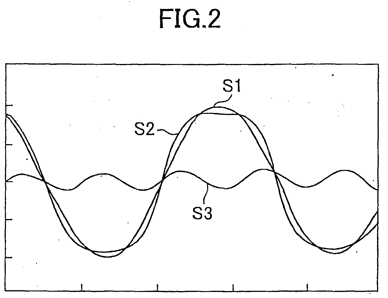
- reference character S1 denotes waveform of "I ⁇ sin ⁇ ” of a current of the fundamental sine wave
- reference character S2 waveform of a current of "I ⁇ sin ⁇ +Ia ⁇ sin3 ⁇ ” obtained by superimposing current having a frequency which is three times as high as that of the fundamental sine wave on the current of the fundamental sine wave
- reference character S3, waveform of a current having a frequency which is three times as high as that of the fundamental sine wave denotes waveform of "I ⁇ sin ⁇ " of a current of the fundamental sine wave
- reference character S2 waveform of a current of "I ⁇ sin ⁇ +Ia ⁇ sin3 ⁇ ” obtained by superimposing current having a frequency which is three times as high as that of the fundamental sine wave on the current of the fundamental sine wave
- the maximum amplitude value of the current of ⁇ I ⁇ sin ⁇ +Ia ⁇ sin3 ⁇ obtained by superimposing the current having a frequency which is three times as high as that of the fundamental sine wave on the current of the fundamental sine wave is smaller than the maximum amplitude value of current I ⁇ sin ⁇ of the fundamental sine wave.
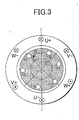
- FIG. 3 is an explanatory view for the principle when the present invention is applied to an induction motor.
- windings of the stator are represented by U, V and W
- windings of the rotor are represented by r, s and t.
- a current is introduced to the rotor by magnetic flux to be generated by a current of the stator winding to generate torque.
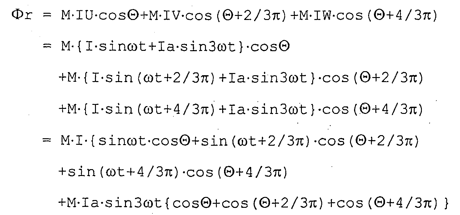
- M is a constant.
- magnetic flux which r-phase winding of the rotor receives becomes only a current component of fundamental sine wave that flows through the stator winding, and is not affected by a current component having a frequency three times as high as the fundamental sine wave.
- magnetic flux ⁇ s, ⁇ t which s, t-phase windings of the rotor receive also becomes a current component of fundamental sine wave. For that reason, torque that is generated also becomes the same as torque generated when only the current of fundamental sine wave flows through each winding of the stator. As shown in FIG.
- FIG. 4 is a block diagram of principal part of the present embodiment in which the current having a frequency which is three times as high as that of the fundamental sine wave is superimposed on the current of the fundamental sine wave to cause the current to flow through the stator winding of the motor for driving the motor.
- FIG. 7 is a block diagram of principal part showing a conventional motor control based on the PWM control.
- windings of U, V and W-phase of the stator are connected to one another (in the example shown in FIG. 7, neutral points of each phase winding are connected), and by a PWM pulse signal to be outputted from a switching control circuit 20, switching elements Tu1, Tu2, Tv1, Tv2, Tw1 and Tw2 of the inverter circuit are switched to flow current through windings of each phase.
- a circuit for flowing current through the U-phase winding will be described.
- a switching element Tu1 and a switching element Tu2 are connected in series in a forward direction, and to each switching element Tu1, Tu2, diodes D are connected in parallel in the opposite direction respectively.
- a switching element Tu3 and a switching element Tu4 are connected in series in a forward direction, and to each switching element Tu3, Tu4, diodes D are connected in parallel in the opposite direction respectively.
- a connecting point between the switching element Tu1 and the switching element Tu2 is connected to one terminal of the U-phase winding, and a connecting point between the switching element Tu3 and the switching element Tu4 is connected to the other terminal of the U-phase winding.
- the same is also applicable to V-phase and W-phase, and there are a pair of series circuits in which two switching elements are connected in series for each phase, and connecting points between two switching elements of the series circuit are connected to terminals of the winding corresponding thereto respectively.
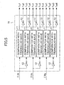
- FIG. 5 is a detailed block diagram showing the switching control circuit 10. For each of the U, V and W-phase, there is constructed a circuit of the same form composed of two each of comparators 11, inversion circuits 12 and inversion circuits 13.
- an inverted command value obtained by inverting the command value IUc by the inversion circuit 12 is compared with the triangular wave by the comparator 11, a switching control signal that is an output signal of the comparison result is outputted to the switching element Tu3 and an inversion switching signal obtained by inverting the switching control signal by the inversion circuit 13 is outputted to the switching element Tu4.
- a switching control signal of a comparison result between an inverted command value obtained by inverting a command value IVc and the triangular wave is outputted to a switching element Tv3, and the inversion switching control signal is outputted to a switching element Tv4.
- a switching control signal of a comparison result between an inverted command value obtained by inverting a command value IWc and the triangular wave is outputted to a switching element Tw3, and the inversion switching control signal is outputted to a switching element Tw4.
- FIG. 6 is an explanatory view illustrating comparison between a command value and the triangular wave by means of the comparator 11 and an output signal.
- the command value IUc of the U-phase is compared with the triangular wave, and when the command value is larger than the triangular wave, a switching control signal (high-level signal) for turning ON the switching element is outputted.
- a switching control signal low-level signal
- this switching control signal is outputted to the switching element Tu1.
- an inversion switching control signal obtained by inverting this signal by the inversion circuit 13 is outputted to the switching element Tu2.
- an inverted command value obtained by inverting the U-phase command value IUc by the inversion circuit 12 is compared with the triangular wave, and in a similar way, when the inverted command value is larger than the triangular wave, a switching control signal (high-level signal) for turning ON the switching element is outputted.
- a switching control signal (low-level signal) for turning OFF the switching element is outputted, and this switching control signal is outputted to the switching element Tu3.
- an inversion switching control signal obtained by inverting this switching control signal by the inversion circuit 13 is outputted to the switching element Tu4. The same is also applicable to the V-phase and the W-phase.
- Switching control signals resulted from the comparison between the command values IUc, IVc, IWc of the U, V and W-phase and the triangular wave are inputted into the switching elements Tu1, Tv1, Tw1, respectively, and when the switching control signal is an ON-signal (high-level signal), these switching elements will be turned ON. Also, a signal obtained by inverting this switching control signal is inputted into the switching elements Tu2, Tv2, and Tw2, and when this inversion switching control signal is an ON signal (high-level signal), these switching elements will be turned ON. As a result, it is impossible that the switching elements Tu1 and Tu2, Tv1 and Tv2, Tw1 and Tw2 are both turned ON to cause the both ends of the DC power source short-circuited.
- switching control signals resulted from a comparison between inverted command values of the command values IUc, IVc, IWc of the U, V and W-phase and the triangular wave are inputted into the switching elements Tu3, Tv3, Tw3, respectively, and the inversion switching control signals are inputted into the switching elements Tu4, Tv4, and Tw4.
- the switching elements Tu3 and Tu4, Tv3 and Tv4, Tw3 and Tw4 are both turned ON to cause the both ends of the DC power source short-circuited.
Landscapes
- Engineering & Computer Science (AREA)
- Power Engineering (AREA)
- Control Of Ac Motors In General (AREA)
- Control Of Motors That Do Not Use Commutators (AREA)
- Inverter Devices (AREA)
Abstract
Description


Claims (6)
- A control unit for a three-phase AC motor in which each winding of three phases is independently constructed, wherein a current obtained by adding a fundamental sine wave current to a current having a frequency which is three times as high as that of said fundamental sine wave current is given to windings of each phase for driving and controlling the three-phase AC motor.
- The motor control unit according to claim 1, wherein said AC motor is a synchronous motor.
- The motor control unit according to claim 1, wherein said AC motor is an induction motor.
- The motor control unit according to claim 1, wherein a current obtained by adding said fundamental sine wave current to a current having a frequency which is three times as high as that of said fundamental sine wave current is supplied, independently for each phase, by a combination of a first series circuit comprising first and second switching elements connected in series, and a second series circuit comprising third and fourth switching elements connected in series.
- The motor control unit according to claim 4, wherein:a command value obtained by adding, to said fundamental sine wave current, a current having a frequency which is three times as high as that of said fundamental sine wave current, and an inverted command value obtained by inverting said command value are each compared with a triangular wave to determine a switching control signal;on the basis of a switching signal determined by said command value, said first and second switching elements are ON/OFF controlled; andon the basis of a switching signal obtained by said inverted command value, said third and fourth switching elements are ON/OFF controlled, thereby causing the current obtained by superimposing, on current of fundamental sine wave, a current having a frequency which is three times as high as that of the fundamental sine wave current to flow through windings of each phase.
- The motor control unit according to claim 1, wherein a current having a frequency which is three times as high as that of said fundamental sine wave current has a predetermined amplitude which is smaller than that of said fundamental sine wave current.
Applications Claiming Priority (2)
| Application Number | Priority Date | Filing Date | Title |
|---|---|---|---|
| JP2003146595A JP3721368B2 (en) | 2003-05-23 | 2003-05-23 | Motor control device |
| JP2003146595 | 2003-05-23 |
Publications (2)
| Publication Number | Publication Date |
|---|---|
| EP1480329A2 true EP1480329A2 (en) | 2004-11-24 |
| EP1480329A3 EP1480329A3 (en) | 2006-11-15 |
Family
ID=33095496
Family Applications (1)
| Application Number | Title | Priority Date | Filing Date |
|---|---|---|---|
| EP04252968A Withdrawn EP1480329A3 (en) | 2003-05-23 | 2004-05-20 | Motor control unit |
Country Status (4)
| Country | Link |
|---|---|
| US (1) | US7126306B2 (en) |
| EP (1) | EP1480329A3 (en) |
| JP (1) | JP3721368B2 (en) |
| CN (1) | CN100373758C (en) |
Cited By (1)
| Publication number | Priority date | Publication date | Assignee | Title |
|---|---|---|---|---|
| WO2016020432A1 (en) | 2014-08-08 | 2016-02-11 | Adb Bvba | Constant current regulator with third harmonic power injection |
Families Citing this family (8)
| Publication number | Priority date | Publication date | Assignee | Title |
|---|---|---|---|---|
| US7786690B2 (en) * | 2007-08-17 | 2010-08-31 | Oriental Motor Co., Ltd. | Motor control apparatus |
| CN103248316B (en) * | 2012-02-10 | 2016-04-20 | 武汉大禹电气有限公司 | Multi-frequency superposition is used for the method for Electric Machine Control |
| JP5876846B2 (en) * | 2013-03-13 | 2016-03-02 | 東芝三菱電機産業システム株式会社 | Electric motor drive |
| EP2983654B1 (en) | 2013-04-08 | 2025-11-12 | BPGbio, Inc. | Treatment of cancer using coenzyme q10 combination therapies |
| JP2015002601A (en) * | 2013-06-14 | 2015-01-05 | 株式会社ソディック | Motor drive device |
| FR3015804B1 (en) * | 2013-12-20 | 2016-01-29 | Valeo Sys Controle Moteur Sas | DRIVE SYSTEM, INVERTER CONTROL METHOD, AND COMPUTER PROGRAM |
| US10498283B2 (en) | 2015-02-06 | 2019-12-03 | Hitachi Automotive Systems, Ltd. | Motor drive device |
| JP6915612B2 (en) | 2016-04-19 | 2021-08-04 | 日本電産株式会社 | Motor and electric power steering device |
Family Cites Families (26)
| Publication number | Priority date | Publication date | Assignee | Title |
|---|---|---|---|---|
| US2437093A (en) * | 1944-05-13 | 1948-03-02 | Lorain Prod Corp | Magnetic frequency changer |
| US3763417A (en) * | 1971-08-26 | 1973-10-02 | Gen Motors Corp | Shut-off arrangement for power controlled rectifiers in a dc to ac inverter |
| DE2345035C2 (en) * | 1973-09-06 | 1975-10-23 | Siemens Ag, 1000 Berlin Und 8000 Muenchen | Method and arrangement for controlling or regulating the speed of a converter-fed three-phase induction machine |
| JPS5523717A (en) | 1978-08-01 | 1980-02-20 | Toyo Electric Mfg Co Ltd | Device for driving ac motor by inverter |
| US5173651A (en) * | 1985-06-28 | 1992-12-22 | Kollmorgen Technologies Corporation | Electrical drive systems |
| KR890004099B1 (en) * | 1987-04-22 | 1989-10-20 | 이이수 | D.c. multi-phase bi-polar brushless motor |
| JP2884880B2 (en) * | 1992-02-12 | 1999-04-19 | 株式会社日立製作所 | Control device for power converter |
| US5227963A (en) * | 1992-04-16 | 1993-07-13 | Westinghouse Electric Corp. | Flat-top waveform generator and pulse-width modulator using same |
| GB9217761D0 (en) * | 1992-08-21 | 1992-10-07 | British Tech Group | Method of and apparatus for determining a rotor displacement parameter |
| JP3042204B2 (en) | 1992-09-16 | 2000-05-15 | 富士電機株式会社 | Control device for synchronous motor |
| JPH06133558A (en) | 1992-10-15 | 1994-05-13 | Fanuc Ltd | Pwm control system |
| KR100347197B1 (en) * | 1994-07-11 | 2002-09-18 | 지멘스 악티엔게젤샤프트 | Direct a.c. converter |
| US6366062B2 (en) * | 1997-12-08 | 2002-04-02 | Microplanet, Inc. | Method and apparatus for electronic power control |
| US5747972A (en) * | 1995-01-11 | 1998-05-05 | Microplanet Ltd. | Method and apparatus for electronic power control |
| US5786673A (en) * | 1995-09-06 | 1998-07-28 | Johnson Consulting, Inc. | Electric motor |
| JPH1169899A (en) | 1997-08-25 | 1999-03-09 | Hitachi Ltd | Control method and control device for induction motor |
| JP3366858B2 (en) * | 1998-05-29 | 2003-01-14 | 株式会社日立製作所 | Control device for rotating electric machine |
| US6731083B2 (en) * | 1998-06-02 | 2004-05-04 | Switched Reluctance Drives, Ltd. | Flux feedback control system |
| JPH11356090A (en) * | 1998-06-10 | 1999-12-24 | Japan Steel Works Ltd:The | Motor control device for electric injection molding machine |
| JP3917305B2 (en) * | 1998-10-22 | 2007-05-23 | ミネベア株式会社 | Motor drive circuit |
| JP3695342B2 (en) * | 2001-04-11 | 2005-09-14 | 株式会社日立製作所 | Electric motor control device |
| KR20040019323A (en) * | 2001-07-04 | 2004-03-05 | 가부시키가이샤 야스카와덴키 | Method and device for controlling currents of synchronous motor |
| JP2003037990A (en) * | 2001-07-24 | 2003-02-07 | Hitachi Ltd | Motor control device |
| JP3801906B2 (en) * | 2001-11-07 | 2006-07-26 | 株式会社日立製作所 | Electric vehicle control device and control method |
| JP2004080975A (en) | 2002-08-22 | 2004-03-11 | Nissan Motor Co Ltd | Motor control device |
| JP4263582B2 (en) * | 2003-11-17 | 2009-05-13 | 本田技研工業株式会社 | Brushless motor control device |
-
2003
- 2003-05-23 JP JP2003146595A patent/JP3721368B2/en not_active Expired - Fee Related
-
2004
- 2004-05-19 US US10/848,129 patent/US7126306B2/en not_active Expired - Fee Related
- 2004-05-20 EP EP04252968A patent/EP1480329A3/en not_active Withdrawn
- 2004-05-24 CN CNB2004100383698A patent/CN100373758C/en not_active Expired - Fee Related
Cited By (1)
| Publication number | Priority date | Publication date | Assignee | Title |
|---|---|---|---|---|
| WO2016020432A1 (en) | 2014-08-08 | 2016-02-11 | Adb Bvba | Constant current regulator with third harmonic power injection |
Also Published As
| Publication number | Publication date |
|---|---|
| EP1480329A3 (en) | 2006-11-15 |
| JP2004350455A (en) | 2004-12-09 |
| CN1574589A (en) | 2005-02-02 |
| US7126306B2 (en) | 2006-10-24 |
| CN100373758C (en) | 2008-03-05 |
| US20050001581A1 (en) | 2005-01-06 |
| JP3721368B2 (en) | 2005-11-30 |
Similar Documents
| Publication | Publication Date | Title |
|---|---|---|
| KR101264884B1 (en) | Electric Motor System | |
| JP5772029B2 (en) | Sensorless brushless motor drive device | |
| JP4288851B2 (en) | Motor drive device | |
| US6242883B1 (en) | Variable speed three-phase motor drive with two inverter circuits | |
| CN103534930A (en) | Control unit | |
| US5406185A (en) | Two-phase inverter drive for a three-phase motor | |
| US7126306B2 (en) | Motor control unit | |
| US10622859B2 (en) | Method and device for operating an electric machine having external or hybrid excitation | |
| US6465973B1 (en) | Permanent magnet 2-phase DC brushless motor | |
| WO2021235548A1 (en) | Motor system | |
| JP2019205269A (en) | Motor drive device | |
| US6040989A (en) | Device and method for generating three-phase sine waves using two pulse-width modulators | |
| JP3250555B2 (en) | Inverter device for switch reluctance motor and control method thereof | |
| JP2000350487A (en) | Control device for brushless motor | |
| US11476788B1 (en) | Optimal open windings inverter for controlling three-phase AC motors | |
| US20240154558A1 (en) | Converter, and method for the operation of a converter | |
| US7388347B2 (en) | Method and inverter for controlling a direct current motor | |
| JP2003018887A (en) | Motor control device and method | |
| EP1528665A1 (en) | Motor control device and motor control method | |
| JP3182322B2 (en) | PWM control device for NPC inverter | |
| EP1096658A2 (en) | Permanent magnet 2-phase DC-brushless motor | |
| JP6681266B2 (en) | Electric motor control device and electric vehicle equipped with the same | |
| JP2003189629A (en) | Control system with power converter | |
| WO2018207719A1 (en) | Variable speed motor device | |
| JP2005033957A (en) | Motor drive device for compressor of air conditioner |
Legal Events
| Date | Code | Title | Description |
|---|---|---|---|
| PUAI | Public reference made under article 153(3) epc to a published international application that has entered the european phase |
Free format text: ORIGINAL CODE: 0009012 |
|
| AK | Designated contracting states |
Kind code of ref document: A2 Designated state(s): AT BE BG CH CY CZ DE DK EE ES FI FR GB GR HU IE IT LI LU MC NL PL PT RO SE SI SK TR |
|
| AX | Request for extension of the european patent |
Extension state: AL HR LT LV MK |
|
| PUAL | Search report despatched |
Free format text: ORIGINAL CODE: 0009013 |
|
| AK | Designated contracting states |
Kind code of ref document: A3 Designated state(s): AT BE BG CH CY CZ DE DK EE ES FI FR GB GR HU IE IT LI LU MC NL PL PT RO SE SI SK TR |
|
| AX | Request for extension of the european patent |
Extension state: AL HR LT LV MK |
|
| 17P | Request for examination filed |
Effective date: 20070510 |
|
| AKX | Designation fees paid |
Designated state(s): DE |
|
| 17Q | First examination report despatched |
Effective date: 20090407 |
|
| STAA | Information on the status of an ep patent application or granted ep patent |
Free format text: STATUS: THE APPLICATION IS DEEMED TO BE WITHDRAWN |
|
| 18D | Application deemed to be withdrawn |
Effective date: 20090818 |