EP1479984A1 - Verfahren und Vorrichtung zur vorbeugenden Fehlererkennung bei elektronisch geregelten und gesteuerten Geräten - Google Patents
Verfahren und Vorrichtung zur vorbeugenden Fehlererkennung bei elektronisch geregelten und gesteuerten Geräten Download PDFInfo
- Publication number
- EP1479984A1 EP1479984A1 EP04001054A EP04001054A EP1479984A1 EP 1479984 A1 EP1479984 A1 EP 1479984A1 EP 04001054 A EP04001054 A EP 04001054A EP 04001054 A EP04001054 A EP 04001054A EP 1479984 A1 EP1479984 A1 EP 1479984A1
- Authority
- EP
- European Patent Office
- Prior art keywords
- preventive
- error detection
- state
- error
- exhaust gas
- Prior art date
- Legal status (The legal status is an assumption and is not a legal conclusion. Google has not performed a legal analysis and makes no representation as to the accuracy of the status listed.)
- Ceased
Links
Images
Classifications
-
- G—PHYSICS
- G05—CONTROLLING; REGULATING
- G05B—CONTROL OR REGULATING SYSTEMS IN GENERAL; FUNCTIONAL ELEMENTS OF SUCH SYSTEMS; MONITORING OR TESTING ARRANGEMENTS FOR SUCH SYSTEMS OR ELEMENTS
- G05B23/00—Testing or monitoring of control systems or parts thereof
- G05B23/02—Electric testing or monitoring
- G05B23/0205—Electric testing or monitoring by means of a monitoring system capable of detecting and responding to faults
- G05B23/0218—Electric testing or monitoring by means of a monitoring system capable of detecting and responding to faults characterised by the fault detection method dealing with either existing or incipient faults
- G05B23/0224—Process history based detection method, e.g. whereby history implies the availability of large amounts of data
- G05B23/0227—Qualitative history assessment, whereby the type of data acted upon, e.g. waveforms, images or patterns, is not relevant, e.g. rule based assessment; if-then decisions
- G05B23/0235—Qualitative history assessment, whereby the type of data acted upon, e.g. waveforms, images or patterns, is not relevant, e.g. rule based assessment; if-then decisions based on a comparison with predetermined threshold or range, e.g. "classical methods", carried out during normal operation; threshold adaptation or choice; when or how to compare with the threshold
-
- F—MECHANICAL ENGINEERING; LIGHTING; HEATING; WEAPONS; BLASTING
- F23—COMBUSTION APPARATUS; COMBUSTION PROCESSES
- F23N—REGULATING OR CONTROLLING COMBUSTION
- F23N5/00—Systems for controlling combustion
- F23N5/02—Systems for controlling combustion using devices responsive to thermal changes or to thermal expansion of a medium
- F23N5/022—Systems for controlling combustion using devices responsive to thermal changes or to thermal expansion of a medium using electronic means
-
- F—MECHANICAL ENGINEERING; LIGHTING; HEATING; WEAPONS; BLASTING
- F23—COMBUSTION APPARATUS; COMBUSTION PROCESSES
- F23N—REGULATING OR CONTROLLING COMBUSTION
- F23N5/00—Systems for controlling combustion
- F23N5/24—Preventing development of abnormal or undesired conditions, i.e. safety arrangements
- F23N5/242—Preventing development of abnormal or undesired conditions, i.e. safety arrangements using electronic means
-
- G—PHYSICS
- G05—CONTROLLING; REGULATING
- G05B—CONTROL OR REGULATING SYSTEMS IN GENERAL; FUNCTIONAL ELEMENTS OF SUCH SYSTEMS; MONITORING OR TESTING ARRANGEMENTS FOR SUCH SYSTEMS OR ELEMENTS
- G05B23/00—Testing or monitoring of control systems or parts thereof
- G05B23/02—Electric testing or monitoring
- G05B23/0205—Electric testing or monitoring by means of a monitoring system capable of detecting and responding to faults
- G05B23/0259—Electric testing or monitoring by means of a monitoring system capable of detecting and responding to faults characterized by the response to fault detection
- G05B23/0283—Predictive maintenance, e.g. involving the monitoring of a system and, based on the monitoring results, taking decisions on the maintenance schedule of the monitored system; Estimating remaining useful life [RUL]
-
- F—MECHANICAL ENGINEERING; LIGHTING; HEATING; WEAPONS; BLASTING
- F23—COMBUSTION APPARATUS; COMBUSTION PROCESSES
- F23N—REGULATING OR CONTROLLING COMBUSTION
- F23N2223/00—Signal processing; Details thereof
- F23N2223/10—Correlation
-
- F—MECHANICAL ENGINEERING; LIGHTING; HEATING; WEAPONS; BLASTING
- F23—COMBUSTION APPARATUS; COMBUSTION PROCESSES
- F23N—REGULATING OR CONTROLLING COMBUSTION
- F23N2225/00—Measuring
- F23N2225/08—Measuring temperature
- F23N2225/19—Measuring temperature outlet temperature water heat-exchanger
-
- F—MECHANICAL ENGINEERING; LIGHTING; HEATING; WEAPONS; BLASTING
- F23—COMBUSTION APPARATUS; COMBUSTION PROCESSES
- F23N—REGULATING OR CONTROLLING COMBUSTION
- F23N2231/00—Fail safe
- F23N2231/10—Fail safe for component failures
-
- F—MECHANICAL ENGINEERING; LIGHTING; HEATING; WEAPONS; BLASTING
- F23—COMBUSTION APPARATUS; COMBUSTION PROCESSES
- F23N—REGULATING OR CONTROLLING COMBUSTION
- F23N2231/00—Fail safe
- F23N2231/20—Warning devices
Definitions
- the invention relates to a method and an apparatus for preventive Fault detection in electronically regulated or controlled devices with means for Detection of at least one state or one measurand.
- the device is operated until a condition or a measured variable is outside the target range located.
- the operating parameters can be changed to make the device better to operate.
- a heater has active means for regulating the fuel gas / air ratio, see above the ratio of fuel gas to air is determined according to a measured value (e.g. lambda probe, Ionization current, carbon monoxide emission). If the measured value lies within a Target range, it is assumed that the measurement is OK. Is the Measured value outside a plausibility range, one assumes a defect and switches the control off.
- a measured value e.g. lambda probe, Ionization current, carbon monoxide emission
- the invention has for its object to early on possible irregularities recognize in order to be able to initiate preventive countermeasures at an early stage.
- the notification is given Carrying out device maintenance using a light indicator or display on the device, Radio transmission to an external display, data transmission via a Telecommunication system or voice output, possibly on several at the same time Species.
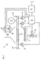
- Fig. 1 shows a heater 1 with a burner 4, which with a controllable gas valve 12 Fuel gas is supplied, and a heat exchanger 5.
- the heat exchanger 5 is Via a return line 13 in which there is a temperature sensor 10, an expansion tank 7 and a pressure sensor 11 are located with a cooling medium - usually water - applied.
- a temperature sensor 9 is located in the flow line 14.
- Above the burner 4 an ionization electrode 6 is arranged.
- the temperature sensor 16 and the ionization electrode 6 are connected to a controller 2. This is in turn connected to a modem 3.
- control 2 opens the gas valve 12.
- the fuel gas flows out of the Burner 4 off and is ignited by an ignition electrode, not shown.
- an ignition electrode not shown.
- the controller 2 Flame detects and therefore keeps the gas valve 12 open.
- Water flows through the Heat exchanger 5.
- the temperature sensors 9 and 10 record the preliminary or Return temperature and pass the corresponding signal on to control 2.
- the Pressure sensor 11 detects the pressure in the line system and indicates the corresponding signal Regulation 2 continues.
- the CO sensor 8 detects the carbon monoxide emission in the exhaust gas path 15 and forwards the corresponding signal to control unit 2. Via the modem 3 can the data of regulation 2 are forwarded. For example, a craftsman monitor the device without having to be on site.
- the number of attempts to ignite a flame is determined using the Ionization electrode 6 detected and processed. Depending on the current one Ignition attempt counter, an error counter is incremented differently. Does that happen Ignition successful in the first attempt, the fault counter is rated weak decremented. In this way, a faulty ignition system can be recognized at an early stage.
- the exhaust gas temperatures are monitored using the temperature sensor 16 monitors. If the temperature exceeds the preset threshold values, the Error counter incremented. With a closed burner operation without If the limit values are exceeded, the error counter is decremented with a weak rating. In this way, a contaminated exhaust system can be recognized at an early stage.
- the water pressure is determined by means of the pressure sensor 11 and its absolute values checked. If the limit values are undershot, the error counter is incremented. To If a limit is exceeded, the counter is decremented. This allows detect inadequate water pressure in the overall system at an early stage.
- the current water pressure is temporarily stored. Increases during burner operation the system pressure is changed from a defective one Expansion tank out. Depending on the pressure increase, the Error counters incremented to different degrees. A burner operation without exceeding the Pressure values decrements the error counter. This allows a defective one to be found at an early stage Recognize the expansion vessel in the overall system.
- the error counter is displayed depending on the limit value exceeded incremented to different degrees. Does not find an impermissible gradient increase instead, the error counter is decremented weakly. This allows you to get in early recognize poorly flowed water system.
- the error counter is incremented to different extents depending on its deviation. If the deviations move back to the initial value, the error counter is decremented. This enables a defective CO sensor to be identified at an early stage.
- the error counters differ depending on the limit value exceeded rate incremented. After successful operation, the counters become weak rated decremented.
- a moving average of measurement is shown, Actuator, counter or state variables over a long and a short one Period formed. If the short of the long mean by more than one If the specified limit value differs, the error detection is activated.
- the limit will be either permanently programmed in the controller or via a communication interface in the production of the devices, when servicing the device via a laptop or via a Remote connection (modem, ISDN, ..) specified.
- the running time of actuators, sensors and / or that of the device is measured with a counter. If the runtime exceeds a predetermined limit value, then the error detection activated.
- the number of switching cycles of actuators, sensors and / or the device is determined with a Counter measured. If the switching cycles exceed a predetermined limit, then error detection activated.
- a sensor exceeds and / or falls below a limit value.
- the error counter exceeds an adjustable threshold value, a status and service message is sent via the modem 3 forwarded to a craftsman who is connected to the device via the telephone network.
- the craftsman Using a modem, the craftsman has the option of carrying out preventive maintenance with their Start and monitor boundary parameters. It can read the meter readings via modem (current, min, max) view.
Landscapes
- Engineering & Computer Science (AREA)
- Chemical & Material Sciences (AREA)
- Combustion & Propulsion (AREA)
- Mechanical Engineering (AREA)
- General Engineering & Computer Science (AREA)
- Physics & Mathematics (AREA)
- General Physics & Mathematics (AREA)
- Automation & Control Theory (AREA)
- Selective Calling Equipment (AREA)
- Testing And Monitoring For Control Systems (AREA)
- Regulation And Control Of Combustion (AREA)
Abstract
Description
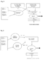
- Meßwerte zeigen zu hohe und/oder zu niedrige Gradienten (z. B. Wassermangelüberwachung)
- Die Differenz zwischen Meßwerten ist zu hoch und / oder zu niedrig. (z.B. Abgasüberwachung)
- Die Meßwerte liegen außerhalb eines definierten Bereichs. (Erkennung von NTC-Kurzschluß)
- Ein Regler erreicht seine maximale und / oder minimale Stellgröße
- Ein bestimmter Betriebszustand (2. Zündversuch) wird eingenommen
- Die Kalibrierung eines Sensor ist nicht mehr möglich (z.B. CO-Sensor).
Claims (15)
- Verfahren zur vorbeugenden Fehlererkennung bei elektronisch geregelten oder gesteuerten Geräten mit Mitteln zur Erkennung mindestens eines Zustandes oder einer Meßgröße, dadurch gekennzeichnet, dass bei definierten Abweichungen mindestens eines Zustandes oder einer Meßgröße innerhalb des zulässigen Betriebsbereiches die Steuerung oder Regelung den Zustand eines möglichen Fehlers oder Mangels erkennt und eine entsprechende Betriebsgröße in den Zustand des Vorliegens eines möglichen Fehlers oder Mangels versetzt.
- Verfahren zur vorbeugenden Fehlererkennung gemäß Anspruch 1, dadurch gekennzeichnet, dass eine Mitteilung zur Durchführung einer Gerätewartung erfolgt.
- Verfahren zur vorbeugenden Fehlererkennung gemäß Anspruch 2, dadurch gekennzeichnet, dass die Mitteilung zur Durchführung einer Gerätewartung mittels Leuchtanzeige oder Display am Gerät, Funkübertragung an ein externes Display, Datenübertragung über ein Telekommunikationssystem und / oder Sprachausgabe erfolgt.
- Verfahren zur vorbeugenden Fehlererkennung gemäß Anspruch 2 oder 3, dadurch gekennzeichnet, dass die Art und optional der Umfang der Abweichung übermittelt wird.
- Verfahren zur vorbeugenden Fehlererkennung gemäß einem der Ansprüche 1 bis 4, dadurch gekennzeichnet, dass das Gerät mit geänderten oder eingeschränkten Parametern weiter betrieben wird.
- Verfahren zur vorbeugenden Fehlererkennung gemäß einem der Ansprüche 1 bis 5, dadurch gekennzeichnet, dass es bei einem Heizgerät eingesetzt wird.
- Verfahren zur vorbeugenden Fehlererkennung gemäß Anspruch 6, dadurch gekennzeichnet, dass Zündung, Abgastemperatur, Wasserdruck, Funktion des Ausdehnungsgefäßes, Wassermangel, Abgassensoren und / oder Ionisationsstromsensoren überwacht werden.
- Vorrichtung zur vorbeugenden Fehlererkennung bei elektronisch geregelten oder gesteuerten Geräten mit Mitteln zur Erkennung mindestens eines Zustandes oder einer Meßgröße, dadurch gekennzeichnet, dass Mittel zum Vergleichen der ermittelten Zustände und Meßgrößen mit Sollzuständen und / oder Sollmeßwerten, Mittel zur Feststellung des Zustand des Vorliegens eines möglichen Fehlers oder Mangels und Mittel zur Datenübertragung vorhanden sind.
- Vorrichtung gemäß Anspruch 8, dadurch gekennzeichnet, dass beim Vorliegen eines möglichen Fehlers oder Mangels die Mittel zur Datenübertragung ein entsprechendes Signal weiterleiten.
- Vorrichtung gemäß Anspruch 8 oder 9, dadurch gekennzeichnet, dass die Mittel zur Datenübertragung leitungsgebunden oder nichtleitungsgebunden zum Beispiel in Form eines Displays, Modems, Netzwerkverbindung, Funkverbindung, Infrarotverbindung oder Bluetoothverbindung arbeiten.
- Vorrichtung gemäß einem der Ansprüche 8 bis 10, dadurch gekennzeichnet, dass Mittel zur Sprachausgabe vorhanden sind.
- Vorrichtung gemäß Anspruch 11, dadurch gekennzeichnet, dass beim Vorliegen eines möglichen Fehlers oder Mangels eine Sprachausgabe erfolgt.
- Vorrichtung gemäß einem der Ansprüche 8 bis 12, dadurch gekennzeichnet, dass beim Vorliegen eines möglichen Fehlers oder Mangels das Gerät mit geänderten oder eingeschränkten Parametern weiter betrieben wird.
- Vorrichtung gemäß einem der Ansprüche 8 bis 13, dadurch gekennzeichnet, dass die Vorrichtung ein Heizgerät ist.
- Vorrichtung gemäß einem der Ansprüche 8 bis 14, dadurch gekennzeichnet, dass Zündung, Abgastemperatur, Wasserdruck, Funktion des Ausdehnungsgefäßes, Wassermangel, Abgassensoren und / oder Ionisationsstromsensoren überwacht werden.
Applications Claiming Priority (4)
| Application Number | Priority Date | Filing Date | Title |
|---|---|---|---|
| DE10303843 | 2003-01-30 | ||
| DE10303843 | 2003-01-30 | ||
| AT11442003 | 2003-07-22 | ||
| AT0114403A AT413060B (de) | 2003-07-22 | 2003-07-22 | Verfahren und vorrichtung zur vorbeugenden fehlererkennung bei elektronisch geregelten oder gesteuerten geräten |
Publications (1)
| Publication Number | Publication Date |
|---|---|
| EP1479984A1 true EP1479984A1 (de) | 2004-11-24 |
Family
ID=32714024
Family Applications (1)
| Application Number | Title | Priority Date | Filing Date |
|---|---|---|---|
| EP04001054A Ceased EP1479984A1 (de) | 2003-01-30 | 2004-01-20 | Verfahren und Vorrichtung zur vorbeugenden Fehlererkennung bei elektronisch geregelten und gesteuerten Geräten |
Country Status (2)
| Country | Link |
|---|---|
| EP (1) | EP1479984A1 (de) |
| DE (1) | DE102004004065B4 (de) |
Cited By (7)
| Publication number | Priority date | Publication date | Assignee | Title |
|---|---|---|---|---|
| DE102005024763B3 (de) * | 2005-05-31 | 2006-06-08 | Stiebel Eltron Gmbh & Co. Kg | Heizgerät und Verfahren zum Steuern eines Heizgerätes |
| US7774165B2 (en) | 2006-08-26 | 2010-08-10 | Peter Renner | State monitoring of machines and technical installations |
| CN101421679B (zh) * | 2006-04-14 | 2011-09-07 | 陶氏环球技术有限责任公司 | 过程监控技术及相关行为 |
| CN102124467B (zh) * | 2007-08-07 | 2015-03-18 | 陶氏环球技术有限责任公司 | 改善聚合物性能预测的方法和具有改善的聚合物性能预测能力的系统 |
| WO2015143543A1 (en) * | 2014-03-26 | 2015-10-01 | Martino Contractors Ltd. | A monitor for a natural gas-fired appliance |
| EP3396248A1 (de) * | 2017-04-28 | 2018-10-31 | Vaillant GmbH | Verfahren zur erkennung von fehlern an einem gassicherheitsventil bei heizgeräten |
| EP3366626B1 (de) | 2017-02-22 | 2021-01-06 | Otis Elevator Company | Aufzugssicherheitssystem und verfahren zur überwachung eines aufzugssystems |
Families Citing this family (5)
| Publication number | Priority date | Publication date | Assignee | Title |
|---|---|---|---|---|
| DE102010021348B4 (de) * | 2010-05-22 | 2012-08-02 | Robert Bosch Gmbh | Heizgerät mit einer Überwachungseinrichtung, Überwachungseinrichtung und Verfahren zu ihrem Betreiben |
| EP3290796B1 (de) * | 2016-09-02 | 2021-01-27 | Robert Bosch GmbH | Verfahren zur kontrolle eines brennstoff-luft-verhältnisses in einem heizsystem sowie eine steuereinheit und ein heizsystem |
| EP3290801B1 (de) * | 2016-09-02 | 2020-08-12 | Robert Bosch GmbH | Verfahren zur kontrolle eines brennstoff-luft-verhältnisses in einem heizsystem sowie eine steuereinheit und ein heizsystem |
| DE102017104526A1 (de) * | 2017-03-03 | 2018-09-06 | Viessmann Werke Gmbh & Co Kg | Verfahren zur Bestimmung der Ursache einer Fehlzündung am Brenner eines Heizkessels |
| DE102017218694A1 (de) * | 2017-10-19 | 2019-04-25 | Robert Bosch Gmbh | Verfahren zu einem Betrieb einer gasbetriebenen Heiz- und/oder Warmwassereinheit |
Citations (5)
| Publication number | Priority date | Publication date | Assignee | Title |
|---|---|---|---|---|
| EP0352217A2 (de) * | 1988-07-20 | 1990-01-24 | Joh. Vaillant GmbH u. Co. | Verfahren zum Steuern und Überwachen eines brennstoffbeheizten Gerätes unter Verwendung zumindest eines Mikrocomputersystems und Vorrichtung zur Durchführung des Verfahrens |
| EP0550055A1 (de) * | 1991-12-30 | 1993-07-07 | Joh. Vaillant GmbH u. Co. | Verfahren zur Überwachung eines Heizgerätes |
| FR2697618A3 (fr) * | 1992-10-29 | 1994-05-06 | Beretta A Ing Spa | Dispositif pour la signalisation visuelle d'anomalies de fonctionnement de chaudières de petite puissance. |
| GB2372130A (en) * | 2000-10-31 | 2002-08-14 | Mulheron Maureen | Monitoring system for a gas-fired boiler providing warning of a sensed condition approaching or in excess of a predetermined limit |
| EP1296103A2 (de) * | 2001-09-21 | 2003-03-26 | Vaillant GmbH | Verfahren zur Fehler-oder Störungsbeseitigung vorzugsweise bei Heizgeräten |
Family Cites Families (1)
| Publication number | Priority date | Publication date | Assignee | Title |
|---|---|---|---|---|
| DE20120609U1 (de) * | 2001-12-20 | 2002-03-21 | Beck IPC GmbH, 35578 Wetzlar | Diagnoseeinrichtung für eine fluidtechnische Einrichtung sowie damit ausgestattete fluidtechnische Einrichtung |
-
2004
- 2004-01-20 DE DE102004004065.6A patent/DE102004004065B4/de not_active Expired - Fee Related
- 2004-01-20 EP EP04001054A patent/EP1479984A1/de not_active Ceased
Patent Citations (5)
| Publication number | Priority date | Publication date | Assignee | Title |
|---|---|---|---|---|
| EP0352217A2 (de) * | 1988-07-20 | 1990-01-24 | Joh. Vaillant GmbH u. Co. | Verfahren zum Steuern und Überwachen eines brennstoffbeheizten Gerätes unter Verwendung zumindest eines Mikrocomputersystems und Vorrichtung zur Durchführung des Verfahrens |
| EP0550055A1 (de) * | 1991-12-30 | 1993-07-07 | Joh. Vaillant GmbH u. Co. | Verfahren zur Überwachung eines Heizgerätes |
| FR2697618A3 (fr) * | 1992-10-29 | 1994-05-06 | Beretta A Ing Spa | Dispositif pour la signalisation visuelle d'anomalies de fonctionnement de chaudières de petite puissance. |
| GB2372130A (en) * | 2000-10-31 | 2002-08-14 | Mulheron Maureen | Monitoring system for a gas-fired boiler providing warning of a sensed condition approaching or in excess of a predetermined limit |
| EP1296103A2 (de) * | 2001-09-21 | 2003-03-26 | Vaillant GmbH | Verfahren zur Fehler-oder Störungsbeseitigung vorzugsweise bei Heizgeräten |
Cited By (9)
| Publication number | Priority date | Publication date | Assignee | Title |
|---|---|---|---|---|
| DE102005024763B3 (de) * | 2005-05-31 | 2006-06-08 | Stiebel Eltron Gmbh & Co. Kg | Heizgerät und Verfahren zum Steuern eines Heizgerätes |
| CN101421679B (zh) * | 2006-04-14 | 2011-09-07 | 陶氏环球技术有限责任公司 | 过程监控技术及相关行为 |
| US7774165B2 (en) | 2006-08-26 | 2010-08-10 | Peter Renner | State monitoring of machines and technical installations |
| CN102124467B (zh) * | 2007-08-07 | 2015-03-18 | 陶氏环球技术有限责任公司 | 改善聚合物性能预测的方法和具有改善的聚合物性能预测能力的系统 |
| WO2015143543A1 (en) * | 2014-03-26 | 2015-10-01 | Martino Contractors Ltd. | A monitor for a natural gas-fired appliance |
| WO2015143527A1 (en) * | 2014-03-26 | 2015-10-01 | Martino Contractors Ltd. | A monitor for a natural gas-fired appliance |
| US11118789B2 (en) | 2014-03-26 | 2021-09-14 | Martino Contractors Ltd. | Monitor for a natural gas-fired appliance |
| EP3366626B1 (de) | 2017-02-22 | 2021-01-06 | Otis Elevator Company | Aufzugssicherheitssystem und verfahren zur überwachung eines aufzugssystems |
| EP3396248A1 (de) * | 2017-04-28 | 2018-10-31 | Vaillant GmbH | Verfahren zur erkennung von fehlern an einem gassicherheitsventil bei heizgeräten |
Also Published As
| Publication number | Publication date |
|---|---|
| DE102004004065A1 (de) | 2004-08-12 |
| DE102004004065B4 (de) | 2015-10-01 |
Similar Documents
| Publication | Publication Date | Title |
|---|---|---|
| EP3919817B1 (de) | Verfahren und vorrichtung zur erkennung von fehlern beim zünden eines brenners mit einem gebläse für die zufuhr von luft und einem brennstoffventil | |
| DE102004004065B4 (de) | Verfahren zur vorbeugenden Fehlererkennung bei elektronisch geregelten oder gesteuerten Heizungsgeräten | |
| EP3825623B1 (de) | Heizgerät mit notbetriebsregelung | |
| EP2017531B1 (de) | Verfahren zur Überprüfung eines Ionisationselektrodensignals bei Brennern | |
| DE69504541T2 (de) | Fehlererkennung eines Fühlers | |
| EP3290797B1 (de) | Verfahren zum erfassen eines alterungszustands eines heizsystems sowie eine steuereinheit und ein heizsystem | |
| DE102006010107A1 (de) | Verfahren und Vorrichtung zur Erkennung eines an eine Steuerung angeschlossenen Temperatursensors | |
| DE3020228C2 (de) | Sicherheitseinrichtung für brennstoffbeheizte Geräte | |
| AT413060B (de) | Verfahren und vorrichtung zur vorbeugenden fehlererkennung bei elektronisch geregelten oder gesteuerten geräten | |
| EP0352217B1 (de) | Verfahren zum Steuern und Überwachen eines brennstoffbeheizten Gerätes unter Verwendung zumindest eines Mikrocomputersystems und Vorrichtung zur Durchführung des Verfahrens | |
| EP4336100B1 (de) | Verfahren zum feststellen eines flammenrückschlages bei einem heizgerät; regel- und steuergerät, heizgerät und computerprogramm | |
| EP4027058B1 (de) | Verfahren und anordnung zur erkennung von flüssigkeit in einem gebläse eines heizgerätes | |
| DE19747819A1 (de) | Steuer- und Überwachungseinrichtung für ein brennstoffbeheiztes Heizgerät | |
| EP2929248B1 (de) | Verfahren zur verbrennungsregelung bei einem gas- oder ölbrenner | |
| DE10114823A1 (de) | Verfahren und Vorrichtung zur Überwachung von Brennern | |
| EP4089329B1 (de) | Verfahren und vorrichtung zum sicheren wiederstart eines mit hohem wasserstoffanteil betriebenen brenners | |
| WO2020120727A1 (de) | Brennervorrichtung und verfahren zum betreiben einer brennervorrichtung | |
| EP3869102A1 (de) | Verfahren und vorrichtung zur fehlerdiagnose an einem feuerungsautomaten | |
| EP3988843B1 (de) | Verfahren und vorrichtung zum schutz einer abgasanlage eines heizgerätes | |
| EP1462724B1 (de) | Vorrichtung zur Temperaturregelung/-begrenzung für eine Wärmeerzeugungsanlage | |
| EP1039227B1 (de) | Verfahren zur Erkennung und Beurteilung von Zündproblemen | |
| DE4038925C2 (de) | ||
| DE102009022040A1 (de) | Gasbrenner, Flammenüberwachungsvorrichtung und Verfahren zur Flammenüberwachung | |
| EP4145047B1 (de) | Verfahren und anordnung zur erkennung des zündens von flammen in einem verbrennungsraum eines heizgerätes, und computerprogrammprodukt | |
| EP4336102B1 (de) | Verfahren zur bewertung einer installation eines gas-luft-verbundes eines heizgerätes, heizgerät und computerprogramm |
Legal Events
| Date | Code | Title | Description |
|---|---|---|---|
| PUAI | Public reference made under article 153(3) epc to a published international application that has entered the european phase |
Free format text: ORIGINAL CODE: 0009012 |
|
| AK | Designated contracting states |
Kind code of ref document: A1 Designated state(s): AT BE BG CH CY CZ DE DK EE ES FI FR GB GR HU IE IT LI LU MC NL PT RO SE SI SK TR |
|
| AX | Request for extension of the european patent |
Extension state: AL LT LV MK |
|
| 17P | Request for examination filed |
Effective date: 20050518 |
|
| AKX | Designation fees paid |
Designated state(s): AT BE BG CH CY CZ DE DK EE ES FI FR GB GR HU IE IT LI LU MC NL PT RO SE SI SK TR |
|
| 17Q | First examination report despatched |
Effective date: 20070305 |
|
| STAA | Information on the status of an ep patent application or granted ep patent |
Free format text: STATUS: THE APPLICATION HAS BEEN REFUSED |
|
| 18R | Application refused |
Effective date: 20180714 |
|
| RIC1 | Information provided on ipc code assigned before grant |
Ipc: F23N 5/24 20060101ALI20040929BHEP Ipc: F23N 5/12 20060101ALI20040929BHEP Ipc: F23N 5/10 20060101ALI20040929BHEP Ipc: F24H 9/20 20060101AFI20040929BHEP Ipc: F23N 5/00 20060101ALI20040929BHEP |