EP1479960B1 - Connexion par fiche entre un tuyau métallique ondulé et un raccord - Google Patents
Connexion par fiche entre un tuyau métallique ondulé et un raccord Download PDFInfo
- Publication number
- EP1479960B1 EP1479960B1 EP20040008032 EP04008032A EP1479960B1 EP 1479960 B1 EP1479960 B1 EP 1479960B1 EP 20040008032 EP20040008032 EP 20040008032 EP 04008032 A EP04008032 A EP 04008032A EP 1479960 B1 EP1479960 B1 EP 1479960B1
- Authority
- EP
- European Patent Office
- Prior art keywords
- metal hose
- plug connection
- connecting member
- corrugation
- end region
- Prior art date
- Legal status (The legal status is an assumption and is not a legal conclusion. Google has not performed a legal analysis and makes no representation as to the accuracy of the status listed.)
- Expired - Lifetime
Links
- 239000002184 metal Substances 0.000 title claims description 54
- 238000000034 method Methods 0.000 claims description 2
- 238000003780 insertion Methods 0.000 description 6
- 230000037431 insertion Effects 0.000 description 6
- 238000007789 sealing Methods 0.000 description 5
- 239000012530 fluid Substances 0.000 description 1
- 230000014759 maintenance of location Effects 0.000 description 1
- 238000004519 manufacturing process Methods 0.000 description 1
- 238000012986 modification Methods 0.000 description 1
- 230000004048 modification Effects 0.000 description 1
Images

Classifications
-
- F—MECHANICAL ENGINEERING; LIGHTING; HEATING; WEAPONS; BLASTING
- F16—ENGINEERING ELEMENTS AND UNITS; GENERAL MEASURES FOR PRODUCING AND MAINTAINING EFFECTIVE FUNCTIONING OF MACHINES OR INSTALLATIONS; THERMAL INSULATION IN GENERAL
- F16L—PIPES; JOINTS OR FITTINGS FOR PIPES; SUPPORTS FOR PIPES, CABLES OR PROTECTIVE TUBING; MEANS FOR THERMAL INSULATION IN GENERAL
- F16L25/00—Construction or details of pipe joints not provided for in, or of interest apart from, groups F16L13/00 - F16L23/00
- F16L25/0036—Joints for corrugated pipes
- F16L25/0045—Joints for corrugated pipes of the quick-acting type
Definitions
- the invention relates to a plug connection between a ring-corrugated metal hose and a connection piece, wherein the connection piece has a cylindrical surface for receiving a ring-waved end region of the metal hose.
- connection of metal hoses especially if they are made by the meter and are rather inaccurately cut to any point of the hose shafts, to fittings or fittings is problematic especially in terms of a most desirable fluid tightness. Not infrequently, therefore, soldered or welded on site for connecting metal hoses, which is naturally complex and time-consuming.
- DE 100 31 729 A1 in contrast, describes a plug connection of the type mentioned above, in which a ring-corrugated metal tube is pushed onto a smooth tube and sealed by means of a sealing ring, which sits in the interior of a shaft of the metal tube and hangs sealingly against the outer circumference of the smooth tube.
- the pull-out protection is carried out via a to be inserted into the interior of the hose, provided with a ring-waved outer profiling retaining element which engages positively in the corrugation and is clamped or latched on the smooth tube.
- DE 19948007 describes a plug connection according to the preamble of claim 1.
- the present invention seeks to further improve a connector of the type mentioned in terms of their handling.
- a meter-metal hose can be easily inserted into a kind of cylindrical sleeve and fixed by means of the retaining element at this.
- the ring seal which according to the invention sits in one of the troughs, seals against the cylindrical inner surface of the sleeve, so that no special requirements are to be placed on the end face of the inserted metal hose; because the ring seal ensures a reliable sealing of the connector. An inaccurate or non-deburred front edge of the metal tube is tolerable within the scope of the invention.
- the connector according to the invention is therefore simple and at the same time effectively constructed. Special skills and costly work on site accounts, at the same time the cost of manufacturing the elements of the connector according to the invention remain very low.
- the trough in the end region of the metal hose which serves as a seat for an external ring seal, optionally by an outside and from the inside acting on the metal tube forming process has been produced.
- a holding element can be provided a flanged shaft of the metal tube.
- This wave must be deformed by the beading so that it projects beyond the outer diameter of the unaltered shafts radially and forms a flange for fixing to the connector.
- extract safety can then be prepared, for example, that the connector has a terminal integrally formed connecting flange, the connecting flange of the connector and the flanged shaft come to rest on each other and by means of a two flanges form-fitting embracing securing clip be fixed to each other.
- a correspondingly prefabricated metal hose end with optionally already an attached ring seal can thus easily inserted into this connector of the invention and a clip on the two flanges are inserted to make a secure and tight connection of the metal hose end.
- only one securing clip may be provided, which engages through a corresponding recess in the connecting piece into a wave trough of the metal tube and thereby produces the pull-out protection of the metal tube from the connecting piece.
- a centering element can be provided which can be inserted into a trough in the end region of the metal tube and has an outer surface adapted to the cylindrical surface of the connection piece. Such a centering element improves the guidance and the hold of the metal hose in the connection piece.
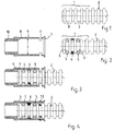
- FIG. 1 initially an end region 1 of a ring-corrugated metal tube 2 is shown.
- the first and third troughs of this end region 1 are designed as sealing seats 3.
- Figure 2 shows the prepared for insertion into a connector 4 end portion 1 of the metal tube 2, wherein in the two sealing seats 3 each have an O-ring seal 5 sits and between, in the second trough, in addition a centering element 6 is inserted with a cylindrical outer contour.
- the connecting piece 4 is formed as a sleeve, with a cylindrical receiving surface 7, a stop 8 for the end of the metal tube 2 and an insertion bevel 9 and a thread 10 for connecting another fitting.
- FIG. 3 shows the assembly phase in which the metal hose 2 has been inserted into the connecting piece 4, wherein the two O-ring seals 5 and the centering element 6 abut against the cylindrical receiving surface 7 of the connecting piece 4.
- the O-ring seals 5 in this case make a fluid-tightness of the connector.
- a securing bracket 12 is provided, which is inserted from the outside through two tangential recesses 11 so into the connector 4, which engages snap into a trough of the metal hose 2 and thus determines this form-fitting connection piece 4.
- FIGS 5 to 7 show the same mounting phases as Figures 1 to 4, for the connector according to the invention. Corresponding elements are provided with the same reference numerals to make the context clearer.
- Figure 5 shows the metal tube 2 with its end portion 1 and this time only a seal seat 3.
- the second and third wave of the metal tube 2 are fused to a cylindrical surface 13 to improve the guidance of the metal tube 2 in the connector 4.
- FIG. 6 shows a schematic representation of the connecting piece 4 with internal cylindrical receiving surface 7, insertion bevel 9 and two recesses 11 for the securing clip 12.
- Figure 7 shows an O-ring Seal 5 has been placed on the seal seat 3.
- FIG. 8 the final state of the connector described here is shown.
- a securing clip 12 has again been inserted through two tangential recesses 11 in the connecting piece 4 in such a way that it engages in a wave valley of the metal tube 2 and thus fixes it in a form-fitting manner on the connecting piece 4.
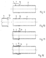
- FIGS 9 to 12 The second embodiment is shown with reference to FIGS 9 to 12 only highly schematic. Again, the mounting phases of Figures 1 to 4 are shown in individual figures again.
- a sealing seat 3 is again present, specifically here in the second trough.
- the fifth wave which is the special feature of this embodiment, has been flanged so that it forms a flange 14 which projects radially beyond the other waves.
- the connecting piece 4 is provided with a connecting flange 15 on the opening side.
- the metal tube 2 is introduced with its flange 14 - after previously inserting an O-ring seal 5 in the seal seat 3 - so far in the connector 4, that the flange 14 of the metal tube 2 and the connecting flange 15 of the connector 4 to come together.
- a securing clip 12 is placed at the end, as Figure 12 shows, which engages around the two flanges 14, 15 form fit.
Landscapes
- Engineering & Computer Science (AREA)
- General Engineering & Computer Science (AREA)
- Mechanical Engineering (AREA)
- Quick-Acting Or Multi-Walled Pipe Joints (AREA)
- Joints That Cut Off Fluids, And Hose Joints (AREA)
Claims (7)
- Connexion par fiche entre un tuyau métallique ondulé (2) et un raccord (4), le raccord (4) étant réalisé comme un manchon enfichable avec une surface cylindrique (7) se trouvant à l'intérieur du raccord (4) permettant de loger une zone d'extrémité ondulée (1) du tuyau métallique (2), un creux d'ondulation au moins étant prévu dans la zone d'extrémité (1) du tuyau métallique (2) en tant que logement pour un joint annulaire externe (5), alors que pour ce qui est de l'extrémité du tuyau métallique (2) derrière le logement du joint annulaire (5), un élément d'arrêt (12, 14) est prévu entre le tuyau métallique (2) et le raccord (4), servant ainsi de sécurité anti-retrait
caractérisée
en ce que deux ondulations ou plus dans la zone d'extrémité (1) du tuyau métallique (2) sont déformées en une surface essentiellement cylindrique (13) dont le diamètre correspond à celui des crêtes des ondulations. - Connexion par fiche selon la revendication 1,
caractérisée
en ce que le logement (3) du joint annulaire externe (5) a été fabriqué au moyen d'un processus de déformation agissant sur le tuyau métallique (2) par l'extérieur et par l'intérieur. - Connexion par fiche selon l'une quelconque des revendications 1 ou 2,
caractérisée
en ce qu'une ondulation du tuyau métallique (2) est prévue en tant qu'élément d'arrêt (12, 14), laquelle ondulation est bridée de telle sorte qu'elle fait saillie de manière radiale par rapport au diamètre extérieur de l'ondulation non déformée et forme une bride (14) servant d'élément d'arrêt sur le raccord (4). - Connexion par fiche selon la revendication 3,
caractérisée
en ce qu'un clip de sécurité (12) est prévu, lequel met en prise selon un engagement positif l'ondulation bridée du tuyau (14) et une bride de raccordement (15) formée sur le raccord (4) et les fixe ainsi l'un à l'autre. - Connexion par fiche selon l'une quelconque des revendications 1 ou 2,
caractérisée
en ce qu'un clip de sécurité (12) est prévu en tant qu'élément d'arrêt, lequel entre en prise à travers un évidement tangentiel correspondant (11) dans le raccord (4) dans un creux d'ondulation du tuyau métallique (2). - Connexion par fiche selon l'une quelconque des revendications 1 à 5,
caractérisée
en ce que plusieurs logements sont présents pour chaque joint annulaire (5). - Connexion par fiche selon l'une quelconque des revendications 1 à 5,
caractérisée
en ce qu'un élément de centrage (6) pouvant être installé dans un creux d'ondulation au niveau de la zone d'extrémité (1) du tuyau métallique (2) est prévu, lequel présente une surface extérieure adaptée à la surface cylindrique (7) du raccord (4).
Applications Claiming Priority (2)
| Application Number | Priority Date | Filing Date | Title |
|---|---|---|---|
| DE20307753U | 2003-05-17 | ||
| DE20307753U DE20307753U1 (de) | 2003-05-17 | 2003-05-17 | Steckverbindung zwischen einem ringgewellten Metallschlauch und einem Anschlussstück |
Publications (2)
| Publication Number | Publication Date |
|---|---|
| EP1479960A1 EP1479960A1 (fr) | 2004-11-24 |
| EP1479960B1 true EP1479960B1 (fr) | 2006-08-23 |
Family
ID=27588957
Family Applications (1)
| Application Number | Title | Priority Date | Filing Date |
|---|---|---|---|
| EP20040008032 Expired - Lifetime EP1479960B1 (fr) | 2003-05-17 | 2004-04-02 | Connexion par fiche entre un tuyau métallique ondulé et un raccord |
Country Status (2)
| Country | Link |
|---|---|
| EP (1) | EP1479960B1 (fr) |
| DE (2) | DE20307753U1 (fr) |
Families Citing this family (5)
| Publication number | Priority date | Publication date | Assignee | Title |
|---|---|---|---|---|
| ITBS20110008U1 (it) | 2011-02-10 | 2012-08-11 | Tiemme Raccorderie S P A | Raccordo per tubo corrugato |
| HUE028675T2 (en) * | 2011-09-05 | 2016-12-28 | General Electric Technology Gmbh | Electrical switching system |
| AT14850U1 (de) * | 2013-08-01 | 2016-07-15 | Gewie Automotive Gmbh | Verbindung von gewellten Kunststoffschläuchen |
| DE102022110669A1 (de) | 2022-05-02 | 2023-11-02 | Vaillant Gmbh | Verfahren zur Verbindung zweier Endbereiche einer Leitung eines Kältekreises, Leitungsverbindung für einen Kältekreis eines Klimagerätes und Klimagerät |
| DE102024103976A1 (de) | 2024-02-13 | 2025-08-14 | Vaillant Gmbh | Leitungsverbindung für einen Kältekreis eines Klimagerätes, Verfahren zum Herstellen einer Leitungsverbindung und Klimagerät |
Family Cites Families (4)
| Publication number | Priority date | Publication date | Assignee | Title |
|---|---|---|---|---|
| DE19948007A1 (de) * | 1999-10-06 | 2001-05-23 | Hans Skodock Gmbh | Verbindung zwischen einem metallischen Wellrohr und einem Anschlußstück |
| DE29917599U1 (de) * | 1999-10-06 | 2000-01-13 | Hans Skodock GmbH, 30419 Hannover | Druckdichte Verbindung zwischen einem metallischen Wellrohr und einem Anschlußteil |
| EP1103752A1 (fr) * | 1999-11-26 | 2001-05-30 | Eureka Immobiliare S.r.l. | Tube ondulé flexible avec des raccords d'extremité pour systèmes hydrauliques |
| DE10031729C2 (de) | 2000-06-29 | 2002-06-27 | Witzenmann Gmbh | Steckverbindung zwischen einem ringgewellten Schlauch und einem Glattrohr |
-
2003
- 2003-05-17 DE DE20307753U patent/DE20307753U1/de not_active Expired - Lifetime
-
2004
- 2004-04-02 DE DE200450001242 patent/DE502004001242D1/de not_active Expired - Lifetime
- 2004-04-02 EP EP20040008032 patent/EP1479960B1/fr not_active Expired - Lifetime
Also Published As
| Publication number | Publication date |
|---|---|
| DE20307753U1 (de) | 2003-07-10 |
| EP1479960A1 (fr) | 2004-11-24 |
| DE502004001242D1 (de) | 2006-10-05 |
Similar Documents
| Publication | Publication Date | Title |
|---|---|---|
| DE19849574B4 (de) | Rohrverbindung zwischen einem Sammler eines Kraftfahrzeugwärmetauschers und einer äußeren Rohrleitung für das innere Wärmetauschfluid | |
| EP3596377B1 (fr) | Pièce de raccordement destinée à être reliée à au moins un tube et procédé de réalisation d'un assemblage | |
| EP2246607B1 (fr) | Raccord pour tuyaux d'eau | |
| EP1333219A1 (fr) | Raccord à action rapide | |
| DE102007026394A1 (de) | Drehfester Schlauchanschluss | |
| EP3359863B1 (fr) | Raccord emmanchable pour le raccordement de conduites de matières liquides ou gazeuses | |
| EP0214395B1 (fr) | Raccord élastique de tuyaux et spécialement raccord flexible | |
| EP3580487A1 (fr) | Module connecteur destiné à être utilisé dans un véhicule | |
| WO2007045281A1 (fr) | Connexion enfichable au niveau de tubes et de tuyaux, comprenant un anneau d'encliquetage de tubes | |
| EP2915973B1 (fr) | Agencement trémie-tube | |
| WO2019002323A1 (fr) | Manchon de sertissage | |
| EP1907742B1 (fr) | Tuyau souple et procede pour monter un ecrou d'accouplement sur un tuyau souple | |
| EP1479960A1 (fr) | Connexion par fiche entre un tuyau métallique ondulé et un raccord | |
| DE8522203U1 (de) | Tankstutzen | |
| EP3012502B1 (fr) | Dispositif de raccordement pour un tuyau et tuyau avec un tel dispositif | |
| DE4025877C2 (de) | Anschlußvorrichtung für Hydraulik-Rohrleitungen | |
| WO2005066533A1 (fr) | Raccord a compression pour tube ou tuyau | |
| DE10217197A1 (de) | Lösbare Kupplung zur Verbindung zweier Schlauchenden einer aus wenigstens zwei Schläuchen zusammengesetzen, flüssigkeitsführenden Schlauchleitung | |
| WO1995012084A1 (fr) | Procede de montage de flexibles et de tuyaux a haute pression cooperant avec des brides, et auxiliaire de montage | |
| EP1167855B1 (fr) | Connexion par fiche entre un tube ondulé et un tube lisse | |
| EP1890069A2 (fr) | Connecteur à fiches | |
| EP1046854A2 (fr) | Raccord à manchon pour connecter deux tuyaux et un dispositif de verrouillage pour un raccord à manchon | |
| EP1277627A1 (fr) | Tuyau métallique pour airbag d'automobile et procédé pour sa fabrication | |
| DE19900425C2 (de) | Anordnung zum Verbinden oder Anschließen von Rohrleitungen | |
| AT409166B (de) | Elastomermanschette zur dichtenden verbindung zweier rohrenden |
Legal Events
| Date | Code | Title | Description |
|---|---|---|---|
| PUAI | Public reference made under article 153(3) epc to a published international application that has entered the european phase |
Free format text: ORIGINAL CODE: 0009012 |
|
| AK | Designated contracting states |
Kind code of ref document: A1 Designated state(s): AT BE BG CH CY CZ DE DK EE ES FI FR GB GR HU IE IT LI LU MC NL PL PT RO SE SI SK TR |
|
| AX | Request for extension of the european patent |
Extension state: AL HR LT LV MK |
|
| 17P | Request for examination filed |
Effective date: 20050414 |
|
| 17Q | First examination report despatched |
Effective date: 20050628 |
|
| AKX | Designation fees paid |
Designated state(s): DE FR IT |
|
| GRAP | Despatch of communication of intention to grant a patent |
Free format text: ORIGINAL CODE: EPIDOSNIGR1 |
|
| GRAS | Grant fee paid |
Free format text: ORIGINAL CODE: EPIDOSNIGR3 |
|
| GRAA | (expected) grant |
Free format text: ORIGINAL CODE: 0009210 |
|
| AK | Designated contracting states |
Kind code of ref document: B1 Designated state(s): DE FR IT |
|
| PG25 | Lapsed in a contracting state [announced via postgrant information from national office to epo] |
Ref country code: IT Free format text: LAPSE BECAUSE OF FAILURE TO SUBMIT A TRANSLATION OF THE DESCRIPTION OR TO PAY THE FEE WITHIN THE PRESCRIBED TIME-LIMIT;WARNING: LAPSES OF ITALIAN PATENTS WITH EFFECTIVE DATE BEFORE 2007 MAY HAVE OCCURRED AT ANY TIME BEFORE 2007. THE CORRECT EFFECTIVE DATE MAY BE DIFFERENT FROM THE ONE RECORDED. Effective date: 20060823 |
|
| REF | Corresponds to: |
Ref document number: 502004001242 Country of ref document: DE Date of ref document: 20061005 Kind code of ref document: P |
|
| ET | Fr: translation filed | ||
| PLBE | No opposition filed within time limit |
Free format text: ORIGINAL CODE: 0009261 |
|
| STAA | Information on the status of an ep patent application or granted ep patent |
Free format text: STATUS: NO OPPOSITION FILED WITHIN TIME LIMIT |
|
| 26N | No opposition filed |
Effective date: 20070524 |
|
| PGRI | Patent reinstated in contracting state [announced from national office to epo] |
Ref country code: IT Effective date: 20080601 |
|
| PGFP | Annual fee paid to national office [announced via postgrant information from national office to epo] |
Ref country code: IT Payment date: 20130424 Year of fee payment: 10 |
|
| PG25 | Lapsed in a contracting state [announced via postgrant information from national office to epo] |
Ref country code: IT Free format text: LAPSE BECAUSE OF FAILURE TO SUBMIT A TRANSLATION OF THE DESCRIPTION OR TO PAY THE FEE WITHIN THE PRESCRIBED TIME-LIMIT Effective date: 20140402 |
|
| REG | Reference to a national code |
Ref country code: FR Ref legal event code: PLFP Year of fee payment: 13 |
|
| REG | Reference to a national code |
Ref country code: FR Ref legal event code: PLFP Year of fee payment: 14 |
|
| REG | Reference to a national code |
Ref country code: FR Ref legal event code: PLFP Year of fee payment: 15 |
|
| PGFP | Annual fee paid to national office [announced via postgrant information from national office to epo] |
Ref country code: DE Payment date: 20190404 Year of fee payment: 16 |
|
| PGFP | Annual fee paid to national office [announced via postgrant information from national office to epo] |
Ref country code: FR Payment date: 20190423 Year of fee payment: 16 |
|
| REG | Reference to a national code |
Ref country code: DE Ref legal event code: R119 Ref document number: 502004001242 Country of ref document: DE |
|
| PG25 | Lapsed in a contracting state [announced via postgrant information from national office to epo] |
Ref country code: FR Free format text: LAPSE BECAUSE OF NON-PAYMENT OF DUE FEES Effective date: 20200430 Ref country code: DE Free format text: LAPSE BECAUSE OF NON-PAYMENT OF DUE FEES Effective date: 20201103 |