EP1479901A1 - Method and apparatus for controlling an internal combustion engine - Google Patents
Method and apparatus for controlling an internal combustion engine Download PDFInfo
- Publication number
- EP1479901A1 EP1479901A1 EP04300281A EP04300281A EP1479901A1 EP 1479901 A1 EP1479901 A1 EP 1479901A1 EP 04300281 A EP04300281 A EP 04300281A EP 04300281 A EP04300281 A EP 04300281A EP 1479901 A1 EP1479901 A1 EP 1479901A1
- Authority
- EP
- European Patent Office
- Prior art keywords
- engine
- signal
- oscillations
- instantaneous
- information
- Prior art date
- Legal status (The legal status is an assumption and is not a legal conclusion. Google has not performed a legal analysis and makes no representation as to the accuracy of the status listed.)
- Granted
Links
- 238000002485 combustion reaction Methods 0.000 title claims abstract description 14
- 238000000034 method Methods 0.000 title claims description 10
- 230000010355 oscillation Effects 0.000 claims abstract description 37
- 238000001914 filtration Methods 0.000 claims abstract description 22
- 238000011144 upstream manufacturing Methods 0.000 claims abstract description 3
- 238000001514 detection method Methods 0.000 claims description 11
- 239000000446 fuel Substances 0.000 description 9
- 238000013507 mapping Methods 0.000 description 7
- 238000004422 calculation algorithm Methods 0.000 description 5
- 230000001276 controlling effect Effects 0.000 description 5
- 239000007789 gas Substances 0.000 description 4
- 230000008054 signal transmission Effects 0.000 description 4
- 230000005540 biological transmission Effects 0.000 description 3
- 230000000694 effects Effects 0.000 description 3
- 238000002347 injection Methods 0.000 description 3
- 239000007924 injection Substances 0.000 description 3
- 238000005259 measurement Methods 0.000 description 3
- 238000012986 modification Methods 0.000 description 2
- 230000004048 modification Effects 0.000 description 2
- 230000005355 Hall effect Effects 0.000 description 1
- 230000001133 acceleration Effects 0.000 description 1
- 230000008901 benefit Effects 0.000 description 1
- 239000003054 catalyst Substances 0.000 description 1
- 238000012512 characterization method Methods 0.000 description 1
- 230000006835 compression Effects 0.000 description 1
- 238000007906 compression Methods 0.000 description 1
- 238000012937 correction Methods 0.000 description 1
- 238000011161 development Methods 0.000 description 1
- 239000003517 fume Substances 0.000 description 1
- 230000006870 function Effects 0.000 description 1
- 230000003534 oscillatory effect Effects 0.000 description 1
- 239000002245 particle Substances 0.000 description 1
- 238000012545 processing Methods 0.000 description 1
- 238000011084 recovery Methods 0.000 description 1
- 230000001105 regulatory effect Effects 0.000 description 1
- 230000004044 response Effects 0.000 description 1
- 238000012546 transfer Methods 0.000 description 1
Images

Classifications
-
- F—MECHANICAL ENGINEERING; LIGHTING; HEATING; WEAPONS; BLASTING
- F02—COMBUSTION ENGINES; HOT-GAS OR COMBUSTION-PRODUCT ENGINE PLANTS
- F02D—CONTROLLING COMBUSTION ENGINES
- F02D41/00—Electrical control of supply of combustible mixture or its constituents
- F02D41/009—Electrical control of supply of combustible mixture or its constituents using means for generating position or synchronisation signals
-
- F—MECHANICAL ENGINEERING; LIGHTING; HEATING; WEAPONS; BLASTING
- F02—COMBUSTION ENGINES; HOT-GAS OR COMBUSTION-PRODUCT ENGINE PLANTS
- F02D—CONTROLLING COMBUSTION ENGINES
- F02D41/00—Electrical control of supply of combustible mixture or its constituents
- F02D41/30—Controlling fuel injection
- F02D41/38—Controlling fuel injection of the high pressure type
- F02D41/40—Controlling fuel injection of the high pressure type with means for controlling injection timing or duration
- F02D41/406—Electrically controlling a diesel injection pump
- F02D41/407—Electrically controlling a diesel injection pump of the in-line type
-
- Y—GENERAL TAGGING OF NEW TECHNOLOGICAL DEVELOPMENTS; GENERAL TAGGING OF CROSS-SECTIONAL TECHNOLOGIES SPANNING OVER SEVERAL SECTIONS OF THE IPC; TECHNICAL SUBJECTS COVERED BY FORMER USPC CROSS-REFERENCE ART COLLECTIONS [XRACs] AND DIGESTS
- Y02—TECHNOLOGIES OR APPLICATIONS FOR MITIGATION OR ADAPTATION AGAINST CLIMATE CHANGE
- Y02T—CLIMATE CHANGE MITIGATION TECHNOLOGIES RELATED TO TRANSPORTATION
- Y02T10/00—Road transport of goods or passengers
- Y02T10/10—Internal combustion engine [ICE] based vehicles
- Y02T10/40—Engine management systems
Definitions
- the present invention relates to the control of the operation of an internal combustion engine of a motor vehicle.
- Such functional checks consist in managing the internal combustion engine using different sensors and actuator devices associated with a set of control laws or software strategies, stored in a computer on board motor vehicle, called an "electronic control unit" (ECU).
- the electronic control unit also contains in memory different characterization parameters or calibrations of the engine combustion.
- Electronic control unit receives information from all the sensors with which the vehicle is fitted, from so as to allow the computer to know in real time the state of the engine.
- the electronic control unit also receives information concerning the will of the driver for driving the vehicle. This will is expressed by signals corresponding to actions, for example on the accelerator pedal or the brake pedal of the motor vehicle. From these different sizes received by the computer contained in the control unit electronic, it is capable of controlling or regulating all of the motor actuator devices for optimal operation.
- Information relating to the instantaneous rotation regime of the engine is generally obtained by a measurement by means of a Hall effect sensor, which measures the time between two teeth of a target fixed on the crankshaft of the combustion engine.
- the injection computer provides rotation speed information engine snapshot which is calculated every quarter of a turn engine. This information can be averaged on a half turn.
- the instantaneous engine speed signal is the image of engine and motor vehicle acceleration.
- the engine torque is applied on the road via a clutch or converter when the vehicle is equipped with a automatic gearbox, then through a gearbox, a transmission device and vehicle tires in contact with the pavement.
- This set constitutes a kinematic chain which presents inertias, non-linearities due to games, friction, etc., as well as resonances- This results, in the case of a variation in torque requested from the motor, a response on the non-linear instantaneous engine speed signal and which causes a certain number of oscillations to appear at each modification of engine speed.
- the object of the present invention is to prevent the spread of oscillations of the instantaneous engine speed signal so as to very largely eliminate or reduce the oscillations which could result on the development of setpoint signals necessary for managing engine operation, to avoid disturbances in calculation algorithms as well as disturbances in the control loops, therefore deviations in the followed by setpoints.
- the method of controlling the operation of a internal combustion engine of a motor vehicle implements software strategies and uses parameters characteristic of the motor which are stored in an electronic control unit.
- the electronic control unit receives information on the status of the engine in real time and on the will of the vehicle driver. She transmits control or regulation signals for means motor actuators.
- the method uses in particular a information on the instantaneous engine rotation speed. We filters the oscillations of the rotation speed signal engine snapshot before using said signal for information on the engine rotation speed in a software strategy to check the operation of the engine.
- the filtering of the oscillations caused by the kinematic chain is performed in such a way that a delay in the signal transmission is not generated, or practically not generated.
- digital filtering can be carried out.
- a high pass filter e.g. a 2 nd order filter.
- a system for controlling the operation of a internal combustion of a motor vehicle includes an electronic control unit in which are memorized different software strategies and parameters engine specifications.
- the electronic control unit is capable of receiving engine status information in real time and on the will of the driver of the vehicle and to emit signals of control or regulation for motor actuator means, a information received being information on the rotation regime engine snapshot.
- the system includes means for filtering oscillations of the instantaneous engine speed signal arranged upstream of the input of said signal in a software strategy to check the operation of the engine.
- filtering means can be envisaged.
- digital filters for example of the high pass filter type, in particular of the 2nd order.
- FIG 1 there is shown schematically a internal combustion engine 1, of diesel type, supplied with air compressed by a turbocharger group 2 controlled by signals emitted by an electronic control unit UCE, referenced 3 as a whole.
- fresh air supplied to 4 passes through a air filter 5, then at the outlet of filter 5, a flow meter 6 which provides on connection 6 has a measurement signal which can be used in the unit control unit UCE 3.
- the air then enters a compressor 7 mounted on a common shaft 8 with a turbine recovery 9.
- the assembly is advantageously of variable geometry, for example by a controlled modification of the turbine fins 9.
- the compressed air coming from the compressor 7 is brought in via line 10 at the entrance of a heat exchanger 11 which recovers part of the calories from compression.
- the compressed air which has thus cooled, passes through a recirculation valve 12 before being brought in by the line 13 in the intake box 14 of the engine 1.
- the gases exhaust from the exhaust housing 15 are brought by the line 16 on turbine 9 which recovers most of their energy, so as to rotate the compressor 7.
- Part of the exhaust gas is brought in through the pipe 17 on the recirculation valve 12 so as to be partially mixed with the supply air supplying the engine.
- the exhaust gases are supplied via line 18 on an exhaust 19 which may include advantageously a depollution catalyst device and a particles.
- the gases from the exhaust 19 then escape by line 20.
- Fuel is injected into the four cylinders of engine 1 by four injection nozzles 21 controlled by the connections 22 which transmit control signals from the control unit electronic 3.
- the computer 23 receives for example the signal 6a coming from the flow meter 6. It can receive other signals from pressure sensors and temperature not shown, measuring engine parameters 1 to every moment.
- the computer 23 also receives via the connection 24 a signal corresponding to the position of the accelerator pedal 25 operated by the driver. This signal therefore corresponds to the will of the driver of the vehicle requesting a certain torque from the engine drive.
- Information on the instantaneous engine speed is measured by a sensor 26, the signal being transmitted by the connection 27 to a filtering device 28 before being brought in by the connection 29 to one of the inputs of the computer 23 of the electronic control 3.
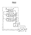
- FIG. 2 illustrates, by way of example, various elements allowing the processing of a request from the driver in the case of a vehicle equipped with a diesel engine, as illustrated in FIG. 1.
- the device is found in the FIG. filter 28 capable of suppressing the oscillations which may appear on the signal N of instantaneous engine rotation speed, as measured by the sensor 26.
- the signal of the engine speed after filtering N f appears on connection 29 and is brought to the inputs of several maps stored in the electronic control unit 3.
- the first map 30 receives as input via the connection 24, the position signal from the accelerator pedal 25 which corresponds to the driver's request. On its second input, the map 30 receives the filtered signal of instantaneous rotation speed of the engine N f .
- the output signal from the map 30 appearing on the connection 31 is a set value for the fuel flow which must be injected into the engine.
- a second map 32 also stored in the electronic control unit 3, receives on one of its inputs the filtered signal of the engine rotation speed N f and on its second input 33 the transmission ratio of the gearbox.
- the output signal from the mapping 32 is brought by the connection 34 to a limiter block 35 which receives the output 31 of the mapping 30 on a second input.
- the limiter block 35 adopts the minimum value received on its two inputs. This results in a limitation of the engine torque, making it possible to avoid damaging the engine or the transmission.
- a second limitation of the set value from the mapping 30 is carried out by means of a third mapping 36, also stored in the electronic control unit 3.
- the mapping 36 receives on one of its inputs the filtered value of the engine rotation speed N f and on its second input the signal from connection 6a which represents the flow of fresh air supplying the compressor 7.
- the output signal from the mapping 36, appearing on connection 37, is brought to a second limiting block 38 which again determines the minimum value of its two inputs, the first being the output of the first limiting block 35.
- the mapping 36, associated with the limiting block 38 therefore achieves a limitation of the flow rate setpoint of fuel to prevent the appearance of exhaust fumes.
- the output signal of the limiter block 38, appearing on the connection 39, is brought to a block 40 defining for example a driving approval strategy and which also receives the signal not filtered from the engine rotation speed N.
- Output 41 of block 40 is the fuel flow control signal injected into the engine.
- the introduction of the filtering device 28, immediately after sensor 26, prevents the spread of these oscillations on the different software strategies of the unit of electronic control.
- the output of the filtering device 28 provides a information on the instantaneous engine speed, all of which the oscillations have been deleted or whose oscillations have been strongly limited.
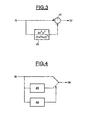
- FIG. 3 shows an embodiment using digital filtering.
- the measured signal of the rotation speed of the motor N is brought to the positive input of an adder 42, which receives on its negative input the signal filtered by a filter 43 which, in the example illustrated, is a high-pass filter of the second order whose transfer function as a Laplace variable is of the type k 2 NOT 2 • p 2 (1+ T NOT • p ) 2 where k N is the gain of the filter, and T N is the time constant of the filtering.
- the second-order high-pass filter 43 makes it possible to isolate the oscillations of the engine speed signal by rejecting the low frequencies. These oscillations which appear on the negative input of the adder 42, are thus subtracted from the information of the engine speed with oscillations, in order to obtain the signal of the engine speed devoid of oscillations N f .
- Such a filtering device is particularly simple to implement.
- FIG. 4 illustrates an alternative embodiment, in which the engine speed signal oscillations are eliminated by limitation of the derivative.
- This embodiment is based on the detection of the oscillations of the engine speed signal.
- a device for limiting the derivative of the engine speed signal is activated.
- the measured engine speed signal N is thus brought to the input of an oscillation detection device 44, as well as to the input of a device for limiting the slope or the derivative 45. If the detection 44 detects the presence of oscillations, the device for limiting the derivative 45 is implemented so as to obtain a filtering effect on the engine speed signal N f , In the absence of detection of the oscillations by the device 44 , the measured signal N is simply transmitted to the output of the device, without correction.
- the oscillation detection can be done for example by detection of the frequency of the oscillations.
Landscapes
- Engineering & Computer Science (AREA)
- Chemical & Material Sciences (AREA)
- Combustion & Propulsion (AREA)
- Mechanical Engineering (AREA)
- General Engineering & Computer Science (AREA)
- Combined Controls Of Internal Combustion Engines (AREA)
- Electrical Control Of Air Or Fuel Supplied To Internal-Combustion Engine (AREA)
- Output Control And Ontrol Of Special Type Engine (AREA)
- Control Of Vehicle Engines Or Engines For Specific Uses (AREA)
- Control Of Throttle Valves Provided In The Intake System Or In The Exhaust System (AREA)
Abstract
Système de contrôle du fonctionnement d'un moteur à combustion interne de véhicule automobile, comprenant une unité de contrôle électronique 3 dans laquelle sont mémorisés différentes stratégies logicielles et paramètres caractéristiques du moteur, l'unité de contrôle électronique étant capable de recevoir des informations 6a sur l'état du moteur en temps réel et la volonté 24 du conducteur du véhicule et d'émettre des signaux 22 de pilotage ou de régulation pour des moyens actionneurs du moteur, une des informations reçues étant une information sur le régime de rotation instantané du moteur, caractérisé par le fait qu'il comprend un moyen de filtrage 28 des oscillations du signal de régime de rotation instantané du moteur disposé en amont de l'entrée dudit signal dans une stratégie logicielle quelconque pour le contrôle du fonctionnement du moteur. <IMAGE>Control system for the operation of an internal combustion engine of a motor vehicle, comprising an electronic control unit 3 in which various software strategies and characteristic parameters of the engine are stored, the electronic control unit being capable of receiving information 6a on the state of the engine in real time and the will 24 of the driver of the vehicle and to transmit control or regulation signals 22 for engine actuator means, one of the information received being information on the instantaneous engine rotation speed , characterized in that it comprises a means of filtering 28 the oscillations of the instantaneous engine speed signal arranged upstream of the input of said signal in any software strategy for controlling the operation of the engine. <IMAGE>
Description
La présente invention concerne le contrôle du fonctionnement d'un moteur à combustion interne de véhicule automobile.The present invention relates to the control of the operation of an internal combustion engine of a motor vehicle.
De tels contrôles du fonctionnement consistent à gérer le moteur à combustion interne au moyen de différents capteurs et dispositifs actionneurs associés à un ensemble des lois de commande ou stratégies logicielles, mémorisé dans un calculateur embarqué sur le véhicule automobile, appelé « unité de contrôle électronique » (UCE). L'unité de contrôle électronique contient également en mémoire différents paramètres de caractérisation ou calibrations du moteur à combustion. L'unité de contrôle électronique reçoit des informations provenant de l'ensemble des capteurs dont le véhicule est équipé, de façon à permettre au calculateur de connaítre en temps réel l'état du moteur. L'unité de contrôle électronique reçoit également des informations concernant la volonté du conducteur pour la conduite du véhicule. Cette volonté se traduit par des signaux correspondant à des actions, par exemple sur la pédale d'accélérateur ou la pédale de frein du véhicule automobile. A partir de ces différentes grandeurs physiques reçues par le calculateur contenu dans l'unité de contrôle électronique, celle-ci est capable de piloter ou réguler l'ensemble des dispositifs actionneurs du moteur pour un fonctionnement optimal.Such functional checks consist in managing the internal combustion engine using different sensors and actuator devices associated with a set of control laws or software strategies, stored in a computer on board motor vehicle, called an "electronic control unit" (ECU). The electronic control unit also contains in memory different characterization parameters or calibrations of the engine combustion. Electronic control unit receives information from all the sensors with which the vehicle is fitted, from so as to allow the computer to know in real time the state of the engine. The electronic control unit also receives information concerning the will of the driver for driving the vehicle. This will is expressed by signals corresponding to actions, for example on the accelerator pedal or the brake pedal of the motor vehicle. From these different sizes received by the computer contained in the control unit electronic, it is capable of controlling or regulating all of the motor actuator devices for optimal operation.
Parmi les informations essentielles pour le contrôle du fonctionnement d'un moteur, figure en particulier l'information sur le régime de rotation instantané du moteur. En effet, la plupart des valeurs de consigne nécessaires pour le contrôle du fonctionnement d'un moteur à combustion interne sont cartographiées en fonction du signal de régime moteur. Il en est ainsi en particulier des différentes valeurs de couple, de la quantité de carburant, des paramètres d'avance à l'injection ou à l'allumage, des signaux de pression de suralimentation dans le cas d'un moteur surcompressé, des signaux de pression d'alimentation dans un rail commun d'alimentation en carburant, des signaux débit d'air, de richesse, etc. De plus, le signal de régime de rotation instantané du moteur est souvent utilisé dans des algorithmes de calcul, comme par exemple l'algorithme de calcul du débit d'air alimenté dans le moteur. Enfin, on utilise encore le signal du régime de rotation instantané du moteur comme une valeur de mesure dans différentes boucles de régulation, par exemple dans un régulateur du régime de ralenti du moteur.Among the essential information for the control of operation of an engine, in particular information on the instantaneous engine rotation speed. Indeed, most setpoints required for functional check of an internal combustion engine are mapped according to the engine speed signal. This is particularly the case with the different torque values, fuel quantity, advance parameters during injection or ignition, pressure signals supercharging in the case of an overcompressed engine, supply pressure in a common supply rail fuel, air flow, wealth signals, etc. In addition, the signal engine speed is often used in calculation algorithms, such as the algorithm for calculating the air flow supplied to the engine. Finally, we still use the signal of the instantaneous engine speed as a value of measurement in different control loops, for example in a engine idle speed regulator.
En résumé, on trouve au moins trois types d'utilisation de l'information sur le régime de rotation instantané du moteur pour le contrôle du fonctionnement du moteur, à savoir :
- dans l'élaboration des valeurs de consigne nécessaires au contrôle de fonctionnement du moteur,
- dans des algorithmes de calcul,
- dans des boucles de régulation.
- in developing the set values necessary for checking the operation of the engine,
- in calculation algorithms,
- in regulation loops.
L'information relative au régime de rotation instantané du moteur est généralement obtenue par une mesure au moyen d'un capteur à effet Hall, qui permet de mesurer le temps entre deux dents d'une cible fixée sur le vilebrequin du moteur à combustion. Le calculateur d'injection fournit une information du régime de rotation instantané du moteur qui est calculée tous les quarts de tour du moteur. Cette information peut faire l'objet d'un calcul de moyenne sur un demi-tour de rotation.Information relating to the instantaneous rotation regime of the engine is generally obtained by a measurement by means of a Hall effect sensor, which measures the time between two teeth of a target fixed on the crankshaft of the combustion engine. The injection computer provides rotation speed information engine snapshot which is calculated every quarter of a turn engine. This information can be averaged on a half turn.
Le signal de régime de rotation instantané du moteur est l'image de l'accélération du moteur et du véhicule automobile. Le couple moteur est appliqué sur la route par l'intermédiaire d'un embrayage ou d'un convertisseur lorsque le véhicule est équipé d'une boíte de vitesses automatique, puis à travers une boíte de vitesses, un dispositif de transmission et les pneumatiques du véhicule, en contact avec la chaussée. Cet ensemble constitue une chaíne cinématique qui présente des inerties, des non-linéarités dues à des jeux, des frottements, etc., ainsi que des résonances- Il en résulte, dans le cas d'une variation de couple demandée au moteur, une réponse sur le signal de régime de rotation instantané du moteur qui n'est pas linéaire et qui fait apparaítre un certain nombre d'oscillations à chaque modification du régime du moteur. The instantaneous engine speed signal is the image of engine and motor vehicle acceleration. The engine torque is applied on the road via a clutch or converter when the vehicle is equipped with a automatic gearbox, then through a gearbox, a transmission device and vehicle tires in contact with the pavement. This set constitutes a kinematic chain which presents inertias, non-linearities due to games, friction, etc., as well as resonances- This results, in the case of a variation in torque requested from the motor, a response on the non-linear instantaneous engine speed signal and which causes a certain number of oscillations to appear at each modification of engine speed.
On a déjà songé à limiter l'effet de ces oscillations afin qu'elles soient moins ressenties par le conducteur et les passagers du véhicule. A cet effet, on a utilisé des stratégies d'agrément de conduite permettant de moduler le couple moteur. Dans le cas d'un moteur Diesel, on peut ajouter ainsi un terme correctif à la demande de couple effectuée par le conducteur, en fonction du régime du moteur, de la dérivée première et de la dérivée seconde du régime du moteur. Le terme correctif intervient sur le débit du carburant injecté dans le cas d'un moteur Diesel, et sur l'avance à l'allumage dans le cas d'un moteur à essence.We have already thought about limiting the effect of these oscillations in order to less felt by the driver and passengers of the vehicle. To this end, accreditation strategies have been used. driving to modulate the engine torque. In the case of a Diesel engine, we can add a corrective term to the request of torque produced by the driver, depending on the engine speed, of the first derivative and of the second derivative of the engine speed. The corrective term affects the flow of fuel injected into the case of a Diesel engine, and on the ignition advance in the case of a petrol engine.
Dans les deux cas, le terme correctif n'est différent de zéro que si l'ensemble de la chaíne cinématique du véhicule se trouve dans un mode oscillatoire. On constate donc que ces stratégies ne suppriment pas les oscillations, mais se contentent d'en limiter les effets.In both cases, the corrective term is non-zero other than if the entire drive train of the vehicle is in a oscillatory mode. We therefore see that these strategies do not remove not oscillations, but only limit their effects.
La présente invention a pour objet d'éviter la propagation des oscillations du signal de régime de rotation instantané du moteur de façon à supprimer ou réduire très largement les oscillations qui pourraient en résulter sur l'élaboration des signaux de consigne nécessaires à la gestion du fonctionnement du moteur, pour éviter des perturbations dans les algorithmes de calcul ainsi que des perturbations dans les boucles de régulation, donc des écarts sur les suivis des valeurs de consigne.The object of the present invention is to prevent the spread of oscillations of the instantaneous engine speed signal so as to very largely eliminate or reduce the oscillations which could result on the development of setpoint signals necessary for managing engine operation, to avoid disturbances in calculation algorithms as well as disturbances in the control loops, therefore deviations in the followed by setpoints.
A cet effet, le procédé de contrôle du fonctionnement d'un moteur à combustion interne de véhicule automobile met en oeuvre des stratégies logicielles et utilise des paramètres caractéristiques du moteur qui sont mémorisés dans une unité de contrôle électronique. L'unité de contrôle électronique reçoit des informations sur l'état du moteur en temps réel et sur la volonté du conducteur du véhicule. Elle émet des signaux de pilotage ou de régulation pour des moyens actionneurs du moteur. Le procédé utilise en particulier une information sur le régime de rotation instantané du moteur. On effectue un filtrage des oscillations du signal de régime de rotation instantané du moteur avant d'utiliser ledit signal à titre d'information sur le régime de rotation du moteur dans une stratégie logicielle quelconque pour le contrôle du fonctionnement du moteur.To this end, the method of controlling the operation of a internal combustion engine of a motor vehicle implements software strategies and uses parameters characteristic of the motor which are stored in an electronic control unit. The electronic control unit receives information on the status of the engine in real time and on the will of the vehicle driver. She transmits control or regulation signals for means motor actuators. The method uses in particular a information on the instantaneous engine rotation speed. We filters the oscillations of the rotation speed signal engine snapshot before using said signal for information on the engine rotation speed in a software strategy to check the operation of the engine.
De cette manière, on évite la propagation des oscillations du signal de régime de rotation instantané du moteur à l'ensemble des stratégies logicielles utilisant cette information. Les oscillations sont en effet filtrées immédiatement en aval de l'émission du signal correspondant.In this way, the propagation of the oscillations of the instantaneous engine speed signal to all software strategies using this information. The oscillations are indeed filtered immediately downstream of the signal transmission corresponding.
De préférence, le filtrage des oscillations provoquées par la chaíne cinématique est effectué d'une manière telle qu'un retard dans la transmission du signal n'est pas généré, ou pratiquement pas généré.Preferably, the filtering of the oscillations caused by the kinematic chain is performed in such a way that a delay in the signal transmission is not generated, or practically not generated.
Différents types de filtrage peuvent être envisagés à cet effet.Different types of filtering can be envisaged for this purpose.
On peut avantageusement procéder à un filtrage numérique. On peut utiliser à cet égard un filtre passe haut, par exemple un filtre du 2éme ordre.Advantageously, digital filtering can be carried out. Can be used in this respect a high pass filter, e.g. a 2 nd order filter.
Dans un autre mode de mise en oeuvre, on détecte d'éventuelles oscillations du signal de régime de rotation instantané du moteur et on limite la dérivée dudit signal en cas de détection positive.In another mode of implementation, we detect possible oscillations of the instantaneous engine speed signal and limits the derivative of said signal in the event of positive detection.
Un système de contrôle du fonctionnement d'un moteur à combustion interne de véhicule automobile selon l'invention, comprend une unité de contrôle électronique dans laquelle sont mémorisés différentes stratégies logicielles et paramètres caractéristiques du moteur. L'unité de contrôle électronique est capable de recevoir des informations sur l'état du moteur en temps réel et sur la volonté du conducteur du véhicule et d'émettre des signaux de pilotage ou de régulation pour des moyens actionneurs du moteur, une des informations reçues étant une information sur le régime de rotation instantané du moteur. Le système comprend un moyen de filtrage des oscillations du signal de régime de rotation instantané du moteur disposé en amont de l'entrée dudit signal dans une stratégie logicielle quelconque pour le contrôle du fonctionnement du moteur.A system for controlling the operation of a internal combustion of a motor vehicle according to the invention, includes an electronic control unit in which are memorized different software strategies and parameters engine specifications. The electronic control unit is capable of receiving engine status information in real time and on the will of the driver of the vehicle and to emit signals of control or regulation for motor actuator means, a information received being information on the rotation regime engine snapshot. The system includes means for filtering oscillations of the instantaneous engine speed signal arranged upstream of the input of said signal in a software strategy to check the operation of the engine.
Différents types de moyens de filtrage peuvent être envisagés. A titre d'exemples nullement limitatifs, on mentionnera les filtres numériques, par exemple du type filtre passe haut, notamment du 2ème ordre. Different types of filtering means can be envisaged. By way of non-limiting examples, mention will be made of digital filters, for example of the high pass filter type, in particular of the 2nd order.
On peut également utiliser un dispositif de détection d'éventuelles oscillations du signal de régime de rotation instantané du moteur et un dispositif de limitation de la dérivée dudit signal en cas de détection positive.You can also use a detection device possible oscillations of the instantaneous speed signal of the motor and a device for limiting the derivative of said signal in the event positive detection.
L'invention sera mieux comprise à l'étude de quelques modes de réalisation décrits à titre d'exemples nullement limitatifs et illustrés par les dessins annexés, sur lesquels :
- la figure 1 représente schématiquement un exemple de différents éléments d'un système de contrôle du fonctionnement d'un moteur à combustion interne ;
- la figure 2 illustre une partie des stratégies logicielles mémorisées dans l'unité de contrôle électronique illustrée sur la figure 1 ;
- la figure 3 montre un exemple de filtre pouvant être utilisé pour la mise en oeuvre du procédé de l'invention ; et
- la figure 4 montre un autre exemple de dispositif de filtrage pouvant être utilisé dans le cadre de la présente invention.
- FIG. 1 schematically represents an example of different elements of a system for controlling the operation of an internal combustion engine;
- FIG. 2 illustrates part of the software strategies stored in the electronic control unit illustrated in FIG. 1;
- FIG. 3 shows an example of a filter that can be used for implementing the method of the invention; and
- FIG. 4 shows another example of a filtering device which can be used in the context of the present invention.
Sur la figure 1, se trouve représenté schématiquement un moteur à combustion interne 1, du type Diesel, alimenté en air comprimé par un groupe turbocompresseur 2 commandé par des signaux émis par une unité de commande électronique UCE, référencée 3 dans son ensemble.In Figure 1, there is shown schematically a internal combustion engine 1, of diesel type, supplied with air compressed by a turbocharger group 2 controlled by signals emitted by an electronic control unit UCE, referenced 3 as a whole.
De manière plus précise, de l'air frais alimenté en 4 traverse un filtre à air 5, puis à la sortie du filtre 5, un débitmètre 6 qui fournit sur la connexion 6a un signal de mesure qui peut être utilisé dans l'unité de commande électronique UCE 3. L'air pénètre ensuite dans un compresseur 7 monté sur un arbre commun 8 avec une turbine de récupération 9. L'ensemble est avantageusement à géométrie variable, par exemple par une modification commandée des ailettes de la turbine 9. L'air comprimé issu du compresseur 7 est amené par la conduite 10 à l'entrée d'un échangeur de chaleur 11 qui récupère une partie des calories provenant de la compression. L'air comprimé qui s'est ainsi refroidi, traverse une vanne 12 de recirculation avant d'être amené par la conduite 13 dans le boítier d'admission 14 du moteur 1. Les gaz d'échappement issus du boítier d'échappement 15 sont amenés par la conduite 16 sur la turbine 9 qui récupère la majeure partie de leur énergie, de façon à entraíner en rotation le compresseur 7.More precisely, fresh air supplied to 4 passes through a air filter 5, then at the outlet of filter 5, a flow meter 6 which provides on connection 6 has a measurement signal which can be used in the unit control unit UCE 3. The air then enters a compressor 7 mounted on a common shaft 8 with a turbine recovery 9. The assembly is advantageously of variable geometry, for example by a controlled modification of the turbine fins 9. The compressed air coming from the compressor 7 is brought in via line 10 at the entrance of a heat exchanger 11 which recovers part of the calories from compression. The compressed air which has thus cooled, passes through a recirculation valve 12 before being brought in by the line 13 in the intake box 14 of the engine 1. The gases exhaust from the exhaust housing 15 are brought by the line 16 on turbine 9 which recovers most of their energy, so as to rotate the compressor 7.
Une partie des gaz d'échappement est amenée par la conduite 17 sur la vanne de recirculation 12 de façon à être partiellement mélangée avec l'air d'alimentation alimentant le moteur.Part of the exhaust gas is brought in through the pipe 17 on the recirculation valve 12 so as to be partially mixed with the supply air supplying the engine.
A la sortie de la turbine 9, les gaz d'échappement sont amenés par la conduite 18 sur un pot d'échappement 19 qui peut comporter avantageusement un dispositif catalyseur de dépollution et un filtre à particules. Les gaz issus du pot d'échappement 19 s'échappent ensuite par la conduite 20.At the outlet of the turbine 9, the exhaust gases are supplied via line 18 on an exhaust 19 which may include advantageously a depollution catalyst device and a particles. The gases from the exhaust 19 then escape by line 20.
Le carburant est injecté dans les quatre cylindres du moteur 1 par quatre buses d'injection 21 commandées par les connexions 22 qui transmettent les signaux de commande issus de l'unité de commande électronique 3. Celle-ci comporte notamment un calculateur 23 qui reçoit des informations sur l'état du moteur en temps réel. Le calculateur 23 reçoit par exemple le signal 6a issu du débitmètre 6. Il peut recevoir d'autres signaux émanant de capteurs de pression et de température non représentés, mesurant les paramètres du moteur 1 à chaque instant. Le calculateur 23 reçoit également par la connexion 24 un signal correspondant à la position de la pédale d'accélérateur 25 actionnée par le conducteur. Ce signal correspond donc à la volonté du conducteur du véhicule demandant au moteur un certain couple d'entraínement.Fuel is injected into the four cylinders of engine 1 by four injection nozzles 21 controlled by the connections 22 which transmit control signals from the control unit electronic 3. This includes in particular a computer 23 which receives real-time engine status information. The computer 23 receives for example the signal 6a coming from the flow meter 6. It can receive other signals from pressure sensors and temperature not shown, measuring engine parameters 1 to every moment. The computer 23 also receives via the connection 24 a signal corresponding to the position of the accelerator pedal 25 operated by the driver. This signal therefore corresponds to the will of the driver of the vehicle requesting a certain torque from the engine drive.
L'information sur le régime de rotation instantané du moteur est mesurée par un capteur 26, le signal étant transmis par la connexion 27 à un dispositif de filtrage 28 avant d'être amené par la connexion 29 à l'une des entrées du calculateur 23 de l'unité de contrôle électronique 3.Information on the instantaneous engine speed is measured by a sensor 26, the signal being transmitted by the connection 27 to a filtering device 28 before being brought in by the connection 29 to one of the inputs of the computer 23 of the electronic control 3.
La figure 2 illustre, à titre d'exemple, différents éléments permettant le traitement d'une demande du conducteur dans le cas d'un véhicule équipé d'un moteur Diesel, comme illustré sur la figure 1. On retrouve sur la figure le dispositif de filtrage 28 capable de supprimer les oscillations pouvant apparaítre sur le signal N de régime instantané de rotation du moteur, tel que mesuré par le capteur 26. Le signal du régime moteur après filtrage Nf apparaít sur la connexion 29 et est amené aux entrées de plusieurs cartographies mémorisées dans l'unité de contrôle électronique 3. La première cartographie 30 reçoit en entrée par la connexion 24, le signal de position de la pédale d'accélérateur 25 qui correspond à la demande du conducteur. Sur sa deuxième entrée, la cartographie 30 reçoit le signal filtré de régime de rotation instantané du moteur Nf. Le signal de sortie de la cartographie 30 apparaissant sur la connexion 31 est une valeur de consigne du débit de carburant qui doit être injecté dans le moteur. On procède cependant à diverses limitations de cette valeur de consigne. A cet effet, une deuxième cartographie 32, également mémorisée dans l'unité de contrôle électronique 3, reçoit sur l'une de ses entrées le signal filtré du régime de rotation du moteur Nf et sur sa deuxième entrée 33 le rapport de transmission de la boíte de vitesses. Le signal de sortie de la cartographie 32 est amené par la connexion 34 à un bloc limiteur 35 qui reçoit sur une deuxième entrée la sortie 31 de la cartographie 30. Le bloc limiteur 35 adopte la valeur minimale reçue sur ses deux entrées. Il en résulte une limitation du couple moteur, permettant d'éviter de détériorer le moteur ou la transmission.FIG. 2 illustrates, by way of example, various elements allowing the processing of a request from the driver in the case of a vehicle equipped with a diesel engine, as illustrated in FIG. 1. The device is found in the FIG. filter 28 capable of suppressing the oscillations which may appear on the signal N of instantaneous engine rotation speed, as measured by the sensor 26. The signal of the engine speed after filtering N f appears on connection 29 and is brought to the inputs of several maps stored in the electronic control unit 3. The first map 30 receives as input via the connection 24, the position signal from the accelerator pedal 25 which corresponds to the driver's request. On its second input, the map 30 receives the filtered signal of instantaneous rotation speed of the engine N f . The output signal from the map 30 appearing on the connection 31 is a set value for the fuel flow which must be injected into the engine. However, there are various limitations to this setpoint. To this end, a second map 32, also stored in the electronic control unit 3, receives on one of its inputs the filtered signal of the engine rotation speed N f and on its second input 33 the transmission ratio of the gearbox. The output signal from the mapping 32 is brought by the connection 34 to a limiter block 35 which receives the output 31 of the mapping 30 on a second input. The limiter block 35 adopts the minimum value received on its two inputs. This results in a limitation of the engine torque, making it possible to avoid damaging the engine or the transmission.
Une deuxième limitation de la valeur de consigne issue de la cartographie 30 est effectuée au moyen d'une troisième cartographie 36, également mémorisée dans l'unité de contrôle électronique 3. La cartographie 36 reçoit sur l'une de ses entrées la valeur filtrée du régime de rotation du moteur Nf et sur sa deuxième entrée le signal provenant de la connexion 6a qui représente le débit d'air frais alimentant le compresseur 7. Le signal de sortie de la cartographie 36, apparaissant sur la connexion 37, est amené à un deuxième bloc limiteur 38 qui détermine à nouveau la valeur minimale de ses deux entrées, la première étant la sortie du premier bloc limiteur 35. La cartographie 36, associée au bloc limiteur 38, réalise donc une limitation de la valeur de consigne du débit de carburant pour éviter l'apparition de fumées à l'échappement. A second limitation of the set value from the mapping 30 is carried out by means of a third mapping 36, also stored in the electronic control unit 3. The mapping 36 receives on one of its inputs the filtered value of the engine rotation speed N f and on its second input the signal from connection 6a which represents the flow of fresh air supplying the compressor 7. The output signal from the mapping 36, appearing on connection 37, is brought to a second limiting block 38 which again determines the minimum value of its two inputs, the first being the output of the first limiting block 35. The mapping 36, associated with the limiting block 38, therefore achieves a limitation of the flow rate setpoint of fuel to prevent the appearance of exhaust fumes.
Le signal de sortie du bloc limiteur 38, apparaissant sur la connexion 39, est amené à un bloc 40 définissant par exemple une stratégie d'agrément de conduite et qui reçoit en outre le signal non filtré du régime de rotation du moteur N. La sortie 41 du bloc 40 constitue le signal de commande du débit de carburant injecté dans le moteur.The output signal of the limiter block 38, appearing on the connection 39, is brought to a block 40 defining for example a driving approval strategy and which also receives the signal not filtered from the engine rotation speed N. Output 41 of block 40 is the fuel flow control signal injected into the engine.
L'examen de la figure 1 montre l'existence de plusieurs boucles de régulation susceptibles de transmettre les oscillations du signal à la demande de couple moteur ou au signal du débit de carburant injecté. En l'absence de filtrage, il en résulte ainsi une propagation des oscillations sur la valeur de consigne du couple ou du débit de carburant.Examination of Figure 1 shows the existence of several regulation loops capable of transmitting the oscillations of the signal on request of engine torque or on signal of flow rate fuel injected. In the absence of filtering, this results in a propagation of the oscillations on the torque or fuel flow.
L'introduction du dispositif de filtrage 28, immédiatement après le capteur 26, permet d'empêcher la propagation de ces oscillations sur les différentes stratégies logicielles de l'unité de contrôle électronique.The introduction of the filtering device 28, immediately after sensor 26, prevents the spread of these oscillations on the different software strategies of the unit of electronic control.
La sortie du dispositif de filtrage 28 permet de disposer d'une information sur le régime de rotation instantané du moteur dont toutes les oscillations ont été supprimées ou dont les oscillations ont été fortement limitées.The output of the filtering device 28 provides a information on the instantaneous engine speed, all of which the oscillations have been deleted or whose oscillations have been strongly limited.
Pour effectuer le filtrage de ce signal, il est important de ne pas introduire de retard dans la transmission du signal. Diverses méthodes de filtrage peuvent être utilisées.To filter this signal, it is important not to not introduce delay in signal transmission. various filtering methods can be used.
A titre d'exemple, la figure 3 montre un mode de réalisation
utilisant un filtrage numérique. Le signal mesuré du régime de rotation
du moteur N est amené à l'entrée positive d'un additionneur 42, lequel
reçoit sur son entrée négative le signal filtré par un filtre 43 qui, dans
l'exemple illustré, est un filtre passe-haut du deuxième ordre dont la
fonction de transfert en variable de Laplace, est du type
et TN est la constante de temps du filtrage. By way of example, FIG. 3 shows an embodiment using digital filtering. The measured signal of the rotation speed of the motor N is brought to the positive input of an adder 42, which receives on its negative input the signal filtered by a filter 43 which, in the example illustrated, is a high-pass filter of the second order whose transfer function as a Laplace variable is of the type
and T N is the time constant of the filtering.
Le filtre passe-haut 43 du deuxième ordre permet d'isoler les oscillations du signal de régime moteur en rejetant les basses fréquences. Ces oscillations qui apparaissent sur l'entrée négative de l'additionneur 42, sont ainsi soustraites de l'information du régime moteur avec oscillations, afin d'obtenir le signal du régime moteur dénué d'oscillations Nf. Un tel dispositif de filtrage est particulièrement simple à mettre en oeuvre.The second-order high-pass filter 43 makes it possible to isolate the oscillations of the engine speed signal by rejecting the low frequencies. These oscillations which appear on the negative input of the adder 42, are thus subtracted from the information of the engine speed with oscillations, in order to obtain the signal of the engine speed devoid of oscillations N f . Such a filtering device is particularly simple to implement.
La figure 4 illustre une variante de réalisation, dans laquelle les oscillations du signal de régime moteur sont éliminées par limitation de la dérivée.FIG. 4 illustrates an alternative embodiment, in which the engine speed signal oscillations are eliminated by limitation of the derivative.
Ce mode de réalisation repose sur la détection des oscillations du signal de régime moteur. Lorsque de telles oscillations sont détectées, on active un dispositif de limitation de la dérivée du signal de régime moteur. Le signal de régime moteur mesuré N est ainsi amené à l'entrée d'un dispositif de détection des oscillations 44, ainsi qu'à l'entrée d'un dispositif de limitation de la pente ou de la dérivée 45. Si le dispositif de détection 44 détecte la présence d'oscillations, le dispositif de limitation de la dérivée 45 est mis en oeuvre de façon à obtenir un effet de filtrage sur le signal de régime moteur Nf, En l'absence de détection des oscillations par le dispositif 44, le signal mesuré N est simplement transmis à la sortie du dispositif, sans correction.This embodiment is based on the detection of the oscillations of the engine speed signal. When such oscillations are detected, a device for limiting the derivative of the engine speed signal is activated. The measured engine speed signal N is thus brought to the input of an oscillation detection device 44, as well as to the input of a device for limiting the slope or the derivative 45. If the detection 44 detects the presence of oscillations, the device for limiting the derivative 45 is implemented so as to obtain a filtering effect on the engine speed signal N f , In the absence of detection of the oscillations by the device 44 , the measured signal N is simply transmitted to the output of the device, without correction.
La détection des oscillations peut se faire par exemple par détection de la fréquence des oscillations.The oscillation detection can be done for example by detection of the frequency of the oscillations.
L'intérêt d'un tel dispositif de filtrage est de ne présenter aucun retard pour la transmission du signal.The advantage of such a filtering device is that it does not present no delay in signal transmission.
Claims (8)
Applications Claiming Priority (2)
| Application Number | Priority Date | Filing Date | Title |
|---|---|---|---|
| FR0306271 | 2003-05-23 | ||
| FR0306271A FR2855219B1 (en) | 2003-05-23 | 2003-05-23 | METHOD AND SYSTEM FOR CONTROLLING THE OPERATION OF AN INTERNAL COMBUSTION ENGINE OF A MOTOR VEHICLE |
Publications (2)
| Publication Number | Publication Date |
|---|---|
| EP1479901A1 true EP1479901A1 (en) | 2004-11-24 |
| EP1479901B1 EP1479901B1 (en) | 2007-03-28 |
Family
ID=33042031
Family Applications (1)
| Application Number | Title | Priority Date | Filing Date |
|---|---|---|---|
| EP04300281A Expired - Lifetime EP1479901B1 (en) | 2003-05-23 | 2004-05-17 | Method and apparatus for controlling an internal combustion engine |
Country Status (5)
| Country | Link |
|---|---|
| EP (1) | EP1479901B1 (en) |
| AT (1) | ATE358231T1 (en) |
| DE (1) | DE602004005530T2 (en) |
| ES (1) | ES2280921T3 (en) |
| FR (1) | FR2855219B1 (en) |
Citations (5)
| Publication number | Priority date | Publication date | Assignee | Title |
|---|---|---|---|---|
| US4357920A (en) * | 1978-05-12 | 1982-11-09 | Robert Bosch Gmbh | Apparatus for the adjustment of a quantity-metering member of a fuel injection pump |
| US4601270A (en) * | 1983-12-27 | 1986-07-22 | United Technologies Diesel Systems, Inc. | Method and apparatus for torque control of an internal combustion engine as a function of exhaust smoke level |
| EP0266304A1 (en) * | 1986-10-29 | 1988-05-04 | Wayne State University | Cranking fuel control method and apparatus for combustion engines |
| US4817568A (en) * | 1985-08-24 | 1989-04-04 | Gaspower International Limited | Dual fuel compression ignition engine |
| DE10017107A1 (en) * | 2000-04-06 | 2001-10-18 | Bosch Gmbh Robert | Method for compensation of the rotational irregularity in the speed detection |
-
2003
- 2003-05-23 FR FR0306271A patent/FR2855219B1/en not_active Expired - Fee Related
-
2004
- 2004-05-17 DE DE602004005530T patent/DE602004005530T2/en not_active Expired - Lifetime
- 2004-05-17 AT AT04300281T patent/ATE358231T1/en not_active IP Right Cessation
- 2004-05-17 ES ES04300281T patent/ES2280921T3/en not_active Expired - Lifetime
- 2004-05-17 EP EP04300281A patent/EP1479901B1/en not_active Expired - Lifetime
Patent Citations (5)
| Publication number | Priority date | Publication date | Assignee | Title |
|---|---|---|---|---|
| US4357920A (en) * | 1978-05-12 | 1982-11-09 | Robert Bosch Gmbh | Apparatus for the adjustment of a quantity-metering member of a fuel injection pump |
| US4601270A (en) * | 1983-12-27 | 1986-07-22 | United Technologies Diesel Systems, Inc. | Method and apparatus for torque control of an internal combustion engine as a function of exhaust smoke level |
| US4817568A (en) * | 1985-08-24 | 1989-04-04 | Gaspower International Limited | Dual fuel compression ignition engine |
| EP0266304A1 (en) * | 1986-10-29 | 1988-05-04 | Wayne State University | Cranking fuel control method and apparatus for combustion engines |
| DE10017107A1 (en) * | 2000-04-06 | 2001-10-18 | Bosch Gmbh Robert | Method for compensation of the rotational irregularity in the speed detection |
Also Published As
| Publication number | Publication date |
|---|---|
| FR2855219A1 (en) | 2004-11-26 |
| ATE358231T1 (en) | 2007-04-15 |
| EP1479901B1 (en) | 2007-03-28 |
| FR2855219B1 (en) | 2007-04-20 |
| DE602004005530D1 (en) | 2007-05-10 |
| ES2280921T3 (en) | 2007-09-16 |
| DE602004005530T2 (en) | 2007-12-13 |
Similar Documents
| Publication | Publication Date | Title |
|---|---|---|
| EP2935828B1 (en) | Supercharged engine diagnostics method and associated engine | |
| EP1514015B1 (en) | Method for regenerating a motor vehicle particle filter and system for controlling regeneration of such a filter | |
| FR2874237A1 (en) | Supercharged internal combustion engine e.g. gasoline engine, controlling method, involves comparing values of mass air flow, and estimating defect if values have amplitude difference higher than predefined threshold | |
| EP0599729B1 (en) | Method for controlling the exhaust gas recirculation in an internal combustion engine | |
| FR2758590A1 (en) | DEVICE FOR CONTROLLING AN INTERNAL COMBUSTION ENGINE WITH IGNITION CONTROL AND DIRECT INJECTION | |
| FR3006000A1 (en) | METHOD FOR STOPPING A THERMAL MOTOR OF A MOTOR VEHICLE | |
| EP1479901B1 (en) | Method and apparatus for controlling an internal combustion engine | |
| FR3118647A1 (en) | Method for detecting a gas leak in an intake circuit of a motorization device | |
| FR2842869A1 (en) | METHOD FOR ADAPTING AN ADJUSTMENT DISTANCE MODEL FOR AN EXHAUST GAS TURBOCHARGER ADJUSTING MEMBER | |
| EP1574694B1 (en) | Apparatus and method controlling metering of injected fuel in a diesel engine | |
| EP1375880A1 (en) | Method and system for controlling an internal combustion engine | |
| FR2945078A1 (en) | METHOD FOR CONTROLLING THE OPERATION OF AN ENGINE | |
| EP3847353A1 (en) | Device and method for controlling the operational state of a processing unit for gaseous effluents from an internal combustion engine exhaust line | |
| FR2876737A1 (en) | SYSTEM AND METHOD FOR CONTROLLING A REGENERATION PHASE OF A PARTICLE FILTER OF A MOTOR VEHICLE | |
| FR2916229A1 (en) | Pollutant e.g. soot, emission controlling method for motor vehicle, involves estimating quantity of injected fuel based on injection set point, and estimating soot mass from estimation of injected fuel quantity | |
| FR3153634A1 (en) | System and method for managing a clutch device of a mechanical air compressor intended to supercharge an internal combustion engine of a motor vehicle | |
| FR3088957A1 (en) | Device and method for controlling the regeneration of a particulate filter of an exhaust line of an internal combustion engine | |
| FR2864164A1 (en) | METHOD AND SYSTEM FOR CONTROLLING THE OPERATION OF AN INTERNAL COMBUSTION ENGINE OF A MOTOR VEHICLE | |
| FR2876733A1 (en) | SYSTEM AND METHOD FOR CONTROLLING THE REGENERATION OF A PARTICLE FILTER OF AN INTERNAL COMBUSTION ENGINE | |
| FR2923537A1 (en) | Pressure estimation system for diesel engine of motor vehicle, has calculation unit calculating pressure drop ratio of turbine from magnitude representing variation relative to temperature between inlet and outlet of turbine | |
| EP4198288A1 (en) | Method and system for verifying the required conditions for performing a diagnosis of an internal combustion engine of a motor vehicle with hybrid transmission | |
| FR2909719A1 (en) | Internal combustion engine e.g. oil engine, for motor vehicle, has regulation unit for regulating temperature of recycled gas by proportional action on valves based on set point temperature of recycled exhaust gas | |
| WO2023078981A1 (en) | Method and system for monitoring consumers of electrical energy and controlling the engine speed of a motor vehicle | |
| FR2851615A1 (en) | DEVICE AND METHOD FOR CONTROLLING THE FLOW OF FUEL INJECTED IN A DIESEL ENGINE | |
| FR3121478A1 (en) | Supercharged internal combustion engine |
Legal Events
| Date | Code | Title | Description |
|---|---|---|---|
| PUAI | Public reference made under article 153(3) epc to a published international application that has entered the european phase |
Free format text: ORIGINAL CODE: 0009012 |
|
| AK | Designated contracting states |
Kind code of ref document: A1 Designated state(s): AT BE BG CH CY CZ DE DK EE ES FI FR GB GR HU IE IT LI LU MC NL PL PT RO SE SI SK TR |
|
| AX | Request for extension of the european patent |
Extension state: AL HR LT LV MK |
|
| 17P | Request for examination filed |
Effective date: 20050520 |
|
| AKX | Designation fees paid |
Designated state(s): AT BE BG CH CY CZ DE DK EE ES FI FR GB GR HU IE IT LI LU MC NL PL PT RO SE SI SK TR |
|
| GRAP | Despatch of communication of intention to grant a patent |
Free format text: ORIGINAL CODE: EPIDOSNIGR1 |
|
| GRAS | Grant fee paid |
Free format text: ORIGINAL CODE: EPIDOSNIGR3 |
|
| GRAA | (expected) grant |
Free format text: ORIGINAL CODE: 0009210 |
|
| AK | Designated contracting states |
Kind code of ref document: B1 Designated state(s): AT BE BG CH CY CZ DE DK EE ES FI FR GB GR HU IE IT LI LU MC NL PL PT RO SE SI SK TR |
|
| PG25 | Lapsed in a contracting state [announced via postgrant information from national office to epo] |
Ref country code: SI Free format text: LAPSE BECAUSE OF FAILURE TO SUBMIT A TRANSLATION OF THE DESCRIPTION OR TO PAY THE FEE WITHIN THE PRESCRIBED TIME-LIMIT Effective date: 20070328 Ref country code: PL Free format text: LAPSE BECAUSE OF FAILURE TO SUBMIT A TRANSLATION OF THE DESCRIPTION OR TO PAY THE FEE WITHIN THE PRESCRIBED TIME-LIMIT Effective date: 20070328 Ref country code: NL Free format text: LAPSE BECAUSE OF FAILURE TO SUBMIT A TRANSLATION OF THE DESCRIPTION OR TO PAY THE FEE WITHIN THE PRESCRIBED TIME-LIMIT Effective date: 20070328 Ref country code: AT Free format text: LAPSE BECAUSE OF FAILURE TO SUBMIT A TRANSLATION OF THE DESCRIPTION OR TO PAY THE FEE WITHIN THE PRESCRIBED TIME-LIMIT Effective date: 20070328 Ref country code: FI Free format text: LAPSE BECAUSE OF FAILURE TO SUBMIT A TRANSLATION OF THE DESCRIPTION OR TO PAY THE FEE WITHIN THE PRESCRIBED TIME-LIMIT Effective date: 20070328 |
|
| REG | Reference to a national code |
Ref country code: GB Ref legal event code: FG4D Free format text: NOT ENGLISH |
|
| REG | Reference to a national code |
Ref country code: CH Ref legal event code: EP |
|
| REF | Corresponds to: |
Ref document number: 602004005530 Country of ref document: DE Date of ref document: 20070510 Kind code of ref document: P |
|
| REG | Reference to a national code |
Ref country code: IE Ref legal event code: FG4D Free format text: LANGUAGE OF EP DOCUMENT: FRENCH |
|
| GBT | Gb: translation of ep patent filed (gb section 77(6)(a)/1977) |
Effective date: 20070606 |
|
| PG25 | Lapsed in a contracting state [announced via postgrant information from national office to epo] |
Ref country code: SE Free format text: LAPSE BECAUSE OF FAILURE TO SUBMIT A TRANSLATION OF THE DESCRIPTION OR TO PAY THE FEE WITHIN THE PRESCRIBED TIME-LIMIT Effective date: 20070628 |
|
| PG25 | Lapsed in a contracting state [announced via postgrant information from national office to epo] |
Ref country code: PT Free format text: LAPSE BECAUSE OF FAILURE TO SUBMIT A TRANSLATION OF THE DESCRIPTION OR TO PAY THE FEE WITHIN THE PRESCRIBED TIME-LIMIT Effective date: 20070828 |
|
| REG | Reference to a national code |
Ref country code: ES Ref legal event code: FG2A Ref document number: 2280921 Country of ref document: ES Kind code of ref document: T3 |
|
| NLV1 | Nl: lapsed or annulled due to failure to fulfill the requirements of art. 29p and 29m of the patents act | ||
| PG25 | Lapsed in a contracting state [announced via postgrant information from national office to epo] |
Ref country code: SK Free format text: LAPSE BECAUSE OF FAILURE TO SUBMIT A TRANSLATION OF THE DESCRIPTION OR TO PAY THE FEE WITHIN THE PRESCRIBED TIME-LIMIT Effective date: 20070328 |
|
| REG | Reference to a national code |
Ref country code: IE Ref legal event code: FD4D |
|
| BERE | Be: lapsed |
Owner name: RENAULT S.A.S. Effective date: 20070531 |
|
| PG25 | Lapsed in a contracting state [announced via postgrant information from national office to epo] |
Ref country code: CZ Free format text: LAPSE BECAUSE OF FAILURE TO SUBMIT A TRANSLATION OF THE DESCRIPTION OR TO PAY THE FEE WITHIN THE PRESCRIBED TIME-LIMIT Effective date: 20070328 Ref country code: RO Free format text: LAPSE BECAUSE OF FAILURE TO SUBMIT A TRANSLATION OF THE DESCRIPTION OR TO PAY THE FEE WITHIN THE PRESCRIBED TIME-LIMIT Effective date: 20070328 |
|
| PG25 | Lapsed in a contracting state [announced via postgrant information from national office to epo] |
Ref country code: IE Free format text: LAPSE BECAUSE OF FAILURE TO SUBMIT A TRANSLATION OF THE DESCRIPTION OR TO PAY THE FEE WITHIN THE PRESCRIBED TIME-LIMIT Effective date: 20070328 Ref country code: MC Free format text: LAPSE BECAUSE OF NON-PAYMENT OF DUE FEES Effective date: 20070531 Ref country code: DK Free format text: LAPSE BECAUSE OF FAILURE TO SUBMIT A TRANSLATION OF THE DESCRIPTION OR TO PAY THE FEE WITHIN THE PRESCRIBED TIME-LIMIT Effective date: 20070328 |
|
| PLBE | No opposition filed within time limit |
Free format text: ORIGINAL CODE: 0009261 |
|
| STAA | Information on the status of an ep patent application or granted ep patent |
Free format text: STATUS: NO OPPOSITION FILED WITHIN TIME LIMIT |
|
| 26N | No opposition filed |
Effective date: 20080102 |
|
| REG | Reference to a national code |
Ref country code: FR Ref legal event code: ST Effective date: 20080131 |
|
| PG25 | Lapsed in a contracting state [announced via postgrant information from national office to epo] |
Ref country code: BE Free format text: LAPSE BECAUSE OF NON-PAYMENT OF DUE FEES Effective date: 20070531 |
|
| PG25 | Lapsed in a contracting state [announced via postgrant information from national office to epo] |
Ref country code: GR Free format text: LAPSE BECAUSE OF FAILURE TO SUBMIT A TRANSLATION OF THE DESCRIPTION OR TO PAY THE FEE WITHIN THE PRESCRIBED TIME-LIMIT Effective date: 20070629 Ref country code: IT Free format text: LAPSE BECAUSE OF FAILURE TO SUBMIT A TRANSLATION OF THE DESCRIPTION OR TO PAY THE FEE WITHIN THE PRESCRIBED TIME-LIMIT Effective date: 20070328 |
|
| PG25 | Lapsed in a contracting state [announced via postgrant information from national office to epo] |
Ref country code: FR Free format text: LAPSE BECAUSE OF NON-PAYMENT OF DUE FEES Effective date: 20070531 |
|
| REG | Reference to a national code |
Ref country code: CH Ref legal event code: PL |
|
| PG25 | Lapsed in a contracting state [announced via postgrant information from national office to epo] |
Ref country code: EE Free format text: LAPSE BECAUSE OF FAILURE TO SUBMIT A TRANSLATION OF THE DESCRIPTION OR TO PAY THE FEE WITHIN THE PRESCRIBED TIME-LIMIT Effective date: 20070328 Ref country code: CH Free format text: LAPSE BECAUSE OF NON-PAYMENT OF DUE FEES Effective date: 20080531 Ref country code: LI Free format text: LAPSE BECAUSE OF NON-PAYMENT OF DUE FEES Effective date: 20080531 |
|
| PG25 | Lapsed in a contracting state [announced via postgrant information from national office to epo] |
Ref country code: CY Free format text: LAPSE BECAUSE OF FAILURE TO SUBMIT A TRANSLATION OF THE DESCRIPTION OR TO PAY THE FEE WITHIN THE PRESCRIBED TIME-LIMIT Effective date: 20070328 |
|
| PG25 | Lapsed in a contracting state [announced via postgrant information from national office to epo] |
Ref country code: LU Free format text: LAPSE BECAUSE OF NON-PAYMENT OF DUE FEES Effective date: 20070517 Ref country code: BG Free format text: LAPSE BECAUSE OF FAILURE TO SUBMIT A TRANSLATION OF THE DESCRIPTION OR TO PAY THE FEE WITHIN THE PRESCRIBED TIME-LIMIT Effective date: 20070628 |
|
| PG25 | Lapsed in a contracting state [announced via postgrant information from national office to epo] |
Ref country code: HU Free format text: LAPSE BECAUSE OF FAILURE TO SUBMIT A TRANSLATION OF THE DESCRIPTION OR TO PAY THE FEE WITHIN THE PRESCRIBED TIME-LIMIT Effective date: 20070929 Ref country code: TR Free format text: LAPSE BECAUSE OF FAILURE TO SUBMIT A TRANSLATION OF THE DESCRIPTION OR TO PAY THE FEE WITHIN THE PRESCRIBED TIME-LIMIT Effective date: 20070328 |
|
| PGFP | Annual fee paid to national office [announced via postgrant information from national office to epo] |
Ref country code: DE Payment date: 20150521 Year of fee payment: 12 Ref country code: GB Payment date: 20150521 Year of fee payment: 12 Ref country code: ES Payment date: 20150527 Year of fee payment: 12 |
|
| REG | Reference to a national code |
Ref country code: DE Ref legal event code: R119 Ref document number: 602004005530 Country of ref document: DE |
|
| GBPC | Gb: european patent ceased through non-payment of renewal fee |
Effective date: 20160517 |
|
| PG25 | Lapsed in a contracting state [announced via postgrant information from national office to epo] |
Ref country code: DE Free format text: LAPSE BECAUSE OF NON-PAYMENT OF DUE FEES Effective date: 20161201 |
|
| PG25 | Lapsed in a contracting state [announced via postgrant information from national office to epo] |
Ref country code: GB Free format text: LAPSE BECAUSE OF NON-PAYMENT OF DUE FEES Effective date: 20160517 |
|
| PG25 | Lapsed in a contracting state [announced via postgrant information from national office to epo] |
Ref country code: ES Free format text: LAPSE BECAUSE OF NON-PAYMENT OF DUE FEES Effective date: 20160518 |
|
| REG | Reference to a national code |
Ref country code: ES Ref legal event code: FD2A Effective date: 20181204 |