EP1479901A1 - Procédé et système de contrôle du fonctionnement d'un moteur à combustion interne de véhicule automobile - Google Patents
Procédé et système de contrôle du fonctionnement d'un moteur à combustion interne de véhicule automobile Download PDFInfo
- Publication number
- EP1479901A1 EP1479901A1 EP04300281A EP04300281A EP1479901A1 EP 1479901 A1 EP1479901 A1 EP 1479901A1 EP 04300281 A EP04300281 A EP 04300281A EP 04300281 A EP04300281 A EP 04300281A EP 1479901 A1 EP1479901 A1 EP 1479901A1
- Authority
- EP
- European Patent Office
- Prior art keywords
- engine
- signal
- oscillations
- instantaneous
- information
- Prior art date
- Legal status (The legal status is an assumption and is not a legal conclusion. Google has not performed a legal analysis and makes no representation as to the accuracy of the status listed.)
- Granted
Links
- 238000002485 combustion reaction Methods 0.000 title claims abstract description 14
- 238000000034 method Methods 0.000 title claims description 10
- 230000010355 oscillation Effects 0.000 claims abstract description 37
- 238000001914 filtration Methods 0.000 claims abstract description 22
- 238000011144 upstream manufacturing Methods 0.000 claims abstract description 3
- 238000001514 detection method Methods 0.000 claims description 11
- 239000000446 fuel Substances 0.000 description 9
- 238000013507 mapping Methods 0.000 description 7
- 238000004422 calculation algorithm Methods 0.000 description 5
- 230000001276 controlling effect Effects 0.000 description 5
- 239000007789 gas Substances 0.000 description 4
- 230000008054 signal transmission Effects 0.000 description 4
- 230000005540 biological transmission Effects 0.000 description 3
- 230000000694 effects Effects 0.000 description 3
- 238000002347 injection Methods 0.000 description 3
- 239000007924 injection Substances 0.000 description 3
- 238000005259 measurement Methods 0.000 description 3
- 238000012986 modification Methods 0.000 description 2
- 230000004048 modification Effects 0.000 description 2
- 230000005355 Hall effect Effects 0.000 description 1
- 230000001133 acceleration Effects 0.000 description 1
- 230000008901 benefit Effects 0.000 description 1
- 239000003054 catalyst Substances 0.000 description 1
- 238000012512 characterization method Methods 0.000 description 1
- 230000006835 compression Effects 0.000 description 1
- 238000007906 compression Methods 0.000 description 1
- 238000012937 correction Methods 0.000 description 1
- 238000011161 development Methods 0.000 description 1
- 239000003517 fume Substances 0.000 description 1
- 230000006870 function Effects 0.000 description 1
- 230000003534 oscillatory effect Effects 0.000 description 1
- 239000002245 particle Substances 0.000 description 1
- 238000012545 processing Methods 0.000 description 1
- 238000011084 recovery Methods 0.000 description 1
- 230000001105 regulatory effect Effects 0.000 description 1
- 230000004044 response Effects 0.000 description 1
- 238000012546 transfer Methods 0.000 description 1
Images

Classifications
-
- F—MECHANICAL ENGINEERING; LIGHTING; HEATING; WEAPONS; BLASTING
- F02—COMBUSTION ENGINES; HOT-GAS OR COMBUSTION-PRODUCT ENGINE PLANTS
- F02D—CONTROLLING COMBUSTION ENGINES
- F02D41/00—Electrical control of supply of combustible mixture or its constituents
- F02D41/009—Electrical control of supply of combustible mixture or its constituents using means for generating position or synchronisation signals
-
- F—MECHANICAL ENGINEERING; LIGHTING; HEATING; WEAPONS; BLASTING
- F02—COMBUSTION ENGINES; HOT-GAS OR COMBUSTION-PRODUCT ENGINE PLANTS
- F02D—CONTROLLING COMBUSTION ENGINES
- F02D41/00—Electrical control of supply of combustible mixture or its constituents
- F02D41/30—Controlling fuel injection
- F02D41/38—Controlling fuel injection of the high pressure type
- F02D41/40—Controlling fuel injection of the high pressure type with means for controlling injection timing or duration
- F02D41/406—Electrically controlling a diesel injection pump
- F02D41/407—Electrically controlling a diesel injection pump of the in-line type
-
- Y—GENERAL TAGGING OF NEW TECHNOLOGICAL DEVELOPMENTS; GENERAL TAGGING OF CROSS-SECTIONAL TECHNOLOGIES SPANNING OVER SEVERAL SECTIONS OF THE IPC; TECHNICAL SUBJECTS COVERED BY FORMER USPC CROSS-REFERENCE ART COLLECTIONS [XRACs] AND DIGESTS
- Y02—TECHNOLOGIES OR APPLICATIONS FOR MITIGATION OR ADAPTATION AGAINST CLIMATE CHANGE
- Y02T—CLIMATE CHANGE MITIGATION TECHNOLOGIES RELATED TO TRANSPORTATION
- Y02T10/00—Road transport of goods or passengers
- Y02T10/10—Internal combustion engine [ICE] based vehicles
- Y02T10/40—Engine management systems
Definitions
- the present invention relates to the control of the operation of an internal combustion engine of a motor vehicle.
- Such functional checks consist in managing the internal combustion engine using different sensors and actuator devices associated with a set of control laws or software strategies, stored in a computer on board motor vehicle, called an "electronic control unit" (ECU).
- the electronic control unit also contains in memory different characterization parameters or calibrations of the engine combustion.
- Electronic control unit receives information from all the sensors with which the vehicle is fitted, from so as to allow the computer to know in real time the state of the engine.
- the electronic control unit also receives information concerning the will of the driver for driving the vehicle. This will is expressed by signals corresponding to actions, for example on the accelerator pedal or the brake pedal of the motor vehicle. From these different sizes received by the computer contained in the control unit electronic, it is capable of controlling or regulating all of the motor actuator devices for optimal operation.
- Information relating to the instantaneous rotation regime of the engine is generally obtained by a measurement by means of a Hall effect sensor, which measures the time between two teeth of a target fixed on the crankshaft of the combustion engine.
- the injection computer provides rotation speed information engine snapshot which is calculated every quarter of a turn engine. This information can be averaged on a half turn.
- the instantaneous engine speed signal is the image of engine and motor vehicle acceleration.
- the engine torque is applied on the road via a clutch or converter when the vehicle is equipped with a automatic gearbox, then through a gearbox, a transmission device and vehicle tires in contact with the pavement.
- This set constitutes a kinematic chain which presents inertias, non-linearities due to games, friction, etc., as well as resonances- This results, in the case of a variation in torque requested from the motor, a response on the non-linear instantaneous engine speed signal and which causes a certain number of oscillations to appear at each modification of engine speed.
- the object of the present invention is to prevent the spread of oscillations of the instantaneous engine speed signal so as to very largely eliminate or reduce the oscillations which could result on the development of setpoint signals necessary for managing engine operation, to avoid disturbances in calculation algorithms as well as disturbances in the control loops, therefore deviations in the followed by setpoints.
- the method of controlling the operation of a internal combustion engine of a motor vehicle implements software strategies and uses parameters characteristic of the motor which are stored in an electronic control unit.
- the electronic control unit receives information on the status of the engine in real time and on the will of the vehicle driver. She transmits control or regulation signals for means motor actuators.
- the method uses in particular a information on the instantaneous engine rotation speed. We filters the oscillations of the rotation speed signal engine snapshot before using said signal for information on the engine rotation speed in a software strategy to check the operation of the engine.
- the filtering of the oscillations caused by the kinematic chain is performed in such a way that a delay in the signal transmission is not generated, or practically not generated.
- digital filtering can be carried out.
- a high pass filter e.g. a 2 nd order filter.
- a system for controlling the operation of a internal combustion of a motor vehicle includes an electronic control unit in which are memorized different software strategies and parameters engine specifications.
- the electronic control unit is capable of receiving engine status information in real time and on the will of the driver of the vehicle and to emit signals of control or regulation for motor actuator means, a information received being information on the rotation regime engine snapshot.
- the system includes means for filtering oscillations of the instantaneous engine speed signal arranged upstream of the input of said signal in a software strategy to check the operation of the engine.
- filtering means can be envisaged.
- digital filters for example of the high pass filter type, in particular of the 2nd order.
- FIG 1 there is shown schematically a internal combustion engine 1, of diesel type, supplied with air compressed by a turbocharger group 2 controlled by signals emitted by an electronic control unit UCE, referenced 3 as a whole.
- fresh air supplied to 4 passes through a air filter 5, then at the outlet of filter 5, a flow meter 6 which provides on connection 6 has a measurement signal which can be used in the unit control unit UCE 3.
- the air then enters a compressor 7 mounted on a common shaft 8 with a turbine recovery 9.
- the assembly is advantageously of variable geometry, for example by a controlled modification of the turbine fins 9.
- the compressed air coming from the compressor 7 is brought in via line 10 at the entrance of a heat exchanger 11 which recovers part of the calories from compression.
- the compressed air which has thus cooled, passes through a recirculation valve 12 before being brought in by the line 13 in the intake box 14 of the engine 1.
- the gases exhaust from the exhaust housing 15 are brought by the line 16 on turbine 9 which recovers most of their energy, so as to rotate the compressor 7.
- Part of the exhaust gas is brought in through the pipe 17 on the recirculation valve 12 so as to be partially mixed with the supply air supplying the engine.
- the exhaust gases are supplied via line 18 on an exhaust 19 which may include advantageously a depollution catalyst device and a particles.
- the gases from the exhaust 19 then escape by line 20.
- Fuel is injected into the four cylinders of engine 1 by four injection nozzles 21 controlled by the connections 22 which transmit control signals from the control unit electronic 3.
- the computer 23 receives for example the signal 6a coming from the flow meter 6. It can receive other signals from pressure sensors and temperature not shown, measuring engine parameters 1 to every moment.
- the computer 23 also receives via the connection 24 a signal corresponding to the position of the accelerator pedal 25 operated by the driver. This signal therefore corresponds to the will of the driver of the vehicle requesting a certain torque from the engine drive.
- Information on the instantaneous engine speed is measured by a sensor 26, the signal being transmitted by the connection 27 to a filtering device 28 before being brought in by the connection 29 to one of the inputs of the computer 23 of the electronic control 3.
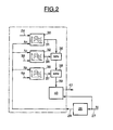
- FIG. 2 illustrates, by way of example, various elements allowing the processing of a request from the driver in the case of a vehicle equipped with a diesel engine, as illustrated in FIG. 1.
- the device is found in the FIG. filter 28 capable of suppressing the oscillations which may appear on the signal N of instantaneous engine rotation speed, as measured by the sensor 26.
- the signal of the engine speed after filtering N f appears on connection 29 and is brought to the inputs of several maps stored in the electronic control unit 3.
- the first map 30 receives as input via the connection 24, the position signal from the accelerator pedal 25 which corresponds to the driver's request. On its second input, the map 30 receives the filtered signal of instantaneous rotation speed of the engine N f .
- the output signal from the map 30 appearing on the connection 31 is a set value for the fuel flow which must be injected into the engine.
- a second map 32 also stored in the electronic control unit 3, receives on one of its inputs the filtered signal of the engine rotation speed N f and on its second input 33 the transmission ratio of the gearbox.
- the output signal from the mapping 32 is brought by the connection 34 to a limiter block 35 which receives the output 31 of the mapping 30 on a second input.
- the limiter block 35 adopts the minimum value received on its two inputs. This results in a limitation of the engine torque, making it possible to avoid damaging the engine or the transmission.
- a second limitation of the set value from the mapping 30 is carried out by means of a third mapping 36, also stored in the electronic control unit 3.
- the mapping 36 receives on one of its inputs the filtered value of the engine rotation speed N f and on its second input the signal from connection 6a which represents the flow of fresh air supplying the compressor 7.
- the output signal from the mapping 36, appearing on connection 37, is brought to a second limiting block 38 which again determines the minimum value of its two inputs, the first being the output of the first limiting block 35.
- the mapping 36, associated with the limiting block 38 therefore achieves a limitation of the flow rate setpoint of fuel to prevent the appearance of exhaust fumes.
- the output signal of the limiter block 38, appearing on the connection 39, is brought to a block 40 defining for example a driving approval strategy and which also receives the signal not filtered from the engine rotation speed N.
- Output 41 of block 40 is the fuel flow control signal injected into the engine.
- the introduction of the filtering device 28, immediately after sensor 26, prevents the spread of these oscillations on the different software strategies of the unit of electronic control.
- the output of the filtering device 28 provides a information on the instantaneous engine speed, all of which the oscillations have been deleted or whose oscillations have been strongly limited.
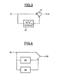
- FIG. 3 shows an embodiment using digital filtering.
- the measured signal of the rotation speed of the motor N is brought to the positive input of an adder 42, which receives on its negative input the signal filtered by a filter 43 which, in the example illustrated, is a high-pass filter of the second order whose transfer function as a Laplace variable is of the type k 2 NOT 2 • p 2 (1+ T NOT • p ) 2 where k N is the gain of the filter, and T N is the time constant of the filtering.
- the second-order high-pass filter 43 makes it possible to isolate the oscillations of the engine speed signal by rejecting the low frequencies. These oscillations which appear on the negative input of the adder 42, are thus subtracted from the information of the engine speed with oscillations, in order to obtain the signal of the engine speed devoid of oscillations N f .
- Such a filtering device is particularly simple to implement.
- FIG. 4 illustrates an alternative embodiment, in which the engine speed signal oscillations are eliminated by limitation of the derivative.
- This embodiment is based on the detection of the oscillations of the engine speed signal.
- a device for limiting the derivative of the engine speed signal is activated.
- the measured engine speed signal N is thus brought to the input of an oscillation detection device 44, as well as to the input of a device for limiting the slope or the derivative 45. If the detection 44 detects the presence of oscillations, the device for limiting the derivative 45 is implemented so as to obtain a filtering effect on the engine speed signal N f , In the absence of detection of the oscillations by the device 44 , the measured signal N is simply transmitted to the output of the device, without correction.
- the oscillation detection can be done for example by detection of the frequency of the oscillations.
Landscapes
- Engineering & Computer Science (AREA)
- Chemical & Material Sciences (AREA)
- Combustion & Propulsion (AREA)
- Mechanical Engineering (AREA)
- General Engineering & Computer Science (AREA)
- Combined Controls Of Internal Combustion Engines (AREA)
- Electrical Control Of Air Or Fuel Supplied To Internal-Combustion Engine (AREA)
- Control Of Throttle Valves Provided In The Intake System Or In The Exhaust System (AREA)
- Output Control And Ontrol Of Special Type Engine (AREA)
- Control Of Vehicle Engines Or Engines For Specific Uses (AREA)
Abstract
Description
- dans l'élaboration des valeurs de consigne nécessaires au contrôle de fonctionnement du moteur,
- dans des algorithmes de calcul,
- dans des boucles de régulation.
- la figure 1 représente schématiquement un exemple de différents éléments d'un système de contrôle du fonctionnement d'un moteur à combustion interne ;
- la figure 2 illustre une partie des stratégies logicielles mémorisées dans l'unité de contrôle électronique illustrée sur la figure 1 ;
- la figure 3 montre un exemple de filtre pouvant être utilisé pour la mise en oeuvre du procédé de l'invention ; et
- la figure 4 montre un autre exemple de dispositif de filtrage pouvant être utilisé dans le cadre de la présente invention.
et TN est la constante de temps du filtrage.
Claims (8)
- Procédé de contrôle du fonctionnement d'un moteur à combustion interne de véhicule automobile, au moyen de stratégies logicielles et de paramètres caractéristiques du moteur mémorisés dans une unité de contrôle électronique (3), laquelle reçoit des informations sur l'état du moteur en temps réel et la volonté (24) du conducteur du véhicule et émet des signaux de pilotage ou de régulation pour des moyens actionneurs du moteur, procédé dans lequel on utilise une information sur le régime de rotation instantané du moteur, caractérisé par le fait que l'on effectue un filtrage des oscillations du signal de régime de rotation instantané du moteur avant d'utiliser ledit signal à titre d'information sur le régime de rotation du moteur dans une stratégie logicielle quelconque pour le contrôle du fonctionnement du moteur.
- Procédé selon la revendication 1, caractérisé par le fait qu'on procède à un filtrage numérique des oscillations du signal de régime de rotation instantané du moteur.
- Procédé selon la revendication 2, caractérisé par le fait qu'on utilise un filtre passe-haut du 2ème ordre.
- Procédé selon la revendication 1, caractérisé par le fait qu'on détecte d'éventuelles oscillations du signal de régime de rotation instantané du moteur et qu'on limite la dérivée dudit signal en cas de détection positive.
- Système de contrôle du fonctionnement d'un moteur à combustion interne de véhicule automobile, comprenant une unité de contrôle électronique (3) dans laquelle sont mémorisés différentes stratégies logicielles et paramètres caractéristiques du moteur, l'unité de contrôle électronique étant capable de recevoir des informations (6a) sur l'état du moteur en temps réel et la volonté (24) du conducteur du véhicule et d'émettre des signaux (22) de pilotage ou de régulation pour des moyens actionneurs du moteur, une des informations reçues étant une information sur le régime de rotation instantané du moteur, caractérisé par le fait qu'il comprend un moyen de filtrage (28) des oscillations du signal de régime de rotation instantané du moteur disposé en amont de l'entrée dudit signal dans une stratégie logicielle quelconque pour le contrôle du fonctionnement du moteur.
- Système selon la revendication 5, caractérisé par le fait que le moyen de filtrage est un filtre numérique (43) des oscillations du signal de régime de rotation instantané du moteur.
- Système selon la revendication 6, caractérisé par le fait que le filtre numérique est un filtre passe-haut du 2ème ordre.
- Système selon la revendication 5, caractérisé par le fait qu'il comprend un dispositif de détection (44) d'éventuelles oscillations du signal de régime de rotation instantané du moteur et un dispositif de limitation (45) de la dérivée dudit signal en cas de détection positive.
Applications Claiming Priority (2)
| Application Number | Priority Date | Filing Date | Title |
|---|---|---|---|
| FR0306271A FR2855219B1 (fr) | 2003-05-23 | 2003-05-23 | Procede et systeme de controle du fonctionnement d'un moteur a combustion interne de vehicule automobile |
| FR0306271 | 2003-05-23 |
Publications (2)
| Publication Number | Publication Date |
|---|---|
| EP1479901A1 true EP1479901A1 (fr) | 2004-11-24 |
| EP1479901B1 EP1479901B1 (fr) | 2007-03-28 |
Family
ID=33042031
Family Applications (1)
| Application Number | Title | Priority Date | Filing Date |
|---|---|---|---|
| EP04300281A Expired - Lifetime EP1479901B1 (fr) | 2003-05-23 | 2004-05-17 | Procédé et système de contrôle du fonctionnement d'un moteur à combustion interne de véhicule automobile |
Country Status (5)
| Country | Link |
|---|---|
| EP (1) | EP1479901B1 (fr) |
| AT (1) | ATE358231T1 (fr) |
| DE (1) | DE602004005530T2 (fr) |
| ES (1) | ES2280921T3 (fr) |
| FR (1) | FR2855219B1 (fr) |
Citations (5)
| Publication number | Priority date | Publication date | Assignee | Title |
|---|---|---|---|---|
| US4357920A (en) * | 1978-05-12 | 1982-11-09 | Robert Bosch Gmbh | Apparatus for the adjustment of a quantity-metering member of a fuel injection pump |
| US4601270A (en) * | 1983-12-27 | 1986-07-22 | United Technologies Diesel Systems, Inc. | Method and apparatus for torque control of an internal combustion engine as a function of exhaust smoke level |
| EP0266304A1 (fr) * | 1986-10-29 | 1988-05-04 | Wayne State University | Méthode et dispositif de commande de carburant au lancement d'un moteur à combustion |
| US4817568A (en) * | 1985-08-24 | 1989-04-04 | Gaspower International Limited | Dual fuel compression ignition engine |
| DE10017107A1 (de) * | 2000-04-06 | 2001-10-18 | Bosch Gmbh Robert | Verfahren zur Kompensation der Drehunförmigkeit bei der Drehzahlerfassung |
-
2003
- 2003-05-23 FR FR0306271A patent/FR2855219B1/fr not_active Expired - Fee Related
-
2004
- 2004-05-17 ES ES04300281T patent/ES2280921T3/es not_active Expired - Lifetime
- 2004-05-17 AT AT04300281T patent/ATE358231T1/de not_active IP Right Cessation
- 2004-05-17 DE DE602004005530T patent/DE602004005530T2/de not_active Expired - Lifetime
- 2004-05-17 EP EP04300281A patent/EP1479901B1/fr not_active Expired - Lifetime
Patent Citations (5)
| Publication number | Priority date | Publication date | Assignee | Title |
|---|---|---|---|---|
| US4357920A (en) * | 1978-05-12 | 1982-11-09 | Robert Bosch Gmbh | Apparatus for the adjustment of a quantity-metering member of a fuel injection pump |
| US4601270A (en) * | 1983-12-27 | 1986-07-22 | United Technologies Diesel Systems, Inc. | Method and apparatus for torque control of an internal combustion engine as a function of exhaust smoke level |
| US4817568A (en) * | 1985-08-24 | 1989-04-04 | Gaspower International Limited | Dual fuel compression ignition engine |
| EP0266304A1 (fr) * | 1986-10-29 | 1988-05-04 | Wayne State University | Méthode et dispositif de commande de carburant au lancement d'un moteur à combustion |
| DE10017107A1 (de) * | 2000-04-06 | 2001-10-18 | Bosch Gmbh Robert | Verfahren zur Kompensation der Drehunförmigkeit bei der Drehzahlerfassung |
Also Published As
| Publication number | Publication date |
|---|---|
| ES2280921T3 (es) | 2007-09-16 |
| FR2855219B1 (fr) | 2007-04-20 |
| FR2855219A1 (fr) | 2004-11-26 |
| DE602004005530T2 (de) | 2007-12-13 |
| ATE358231T1 (de) | 2007-04-15 |
| DE602004005530D1 (de) | 2007-05-10 |
| EP1479901B1 (fr) | 2007-03-28 |
Similar Documents
| Publication | Publication Date | Title |
|---|---|---|
| EP2935828B1 (fr) | Procede de diagnostic d'un moteur suralimente et moteur associe | |
| EP1514015B1 (fr) | Procede de regeneration d'un filtre a particules de vehicule automobile et systeme de commande de la regeneration d'un tel filtre | |
| FR2874237A1 (fr) | Procede et dispositif de gestion d'un moteur a combustion interne | |
| EP0599729B1 (fr) | Procédé de contrÔle du système de recirculation des gaz d'échappement d'un moteur à combustion interne | |
| FR3006000A1 (fr) | Procede d'arret d'un moteur thermique de vehicule automobile | |
| EP1479901B1 (fr) | Procédé et système de contrôle du fonctionnement d'un moteur à combustion interne de véhicule automobile | |
| FR3118647A1 (fr) | Procédé de détection d’une fuite de gaz dans un circuit d’admission d’un dispositif de motorisation | |
| FR2842869A1 (fr) | Procede permettant d'adapter un modele de distance de reglage pour un organe de reglage de turbocompresseur a gaz d'echappement | |
| EP1574694B1 (fr) | Dispositif et procédé de régulation du débit de carburant injecté dans un moteur diesel | |
| EP1375880A1 (fr) | Procédé et système de contrôle de fonctionnement d'un moteur à combustion interne de véhicule automobile | |
| FR2945078A1 (fr) | Procede de controle du fonctionnement d'un moteur | |
| WO2020048657A1 (fr) | Dispositif et procédé de contrôle de l'état de fonctionnement d'un organe de traitement d'effluents gazeux d'une ligne d'échappement d'un moteur à combustion interne | |
| FR2876737A1 (fr) | Systeme et procede de controle d'une phase de regeneration d'un filtre a particules de vehicule automobile | |
| FR2916229A1 (fr) | Procede de controle des emissions polluantes d'un moteur diesel | |
| FR3088957A1 (fr) | Dispositif et procédé de commande de la régénération d'un filtre à particules d'une ligne d'échappement d'un moteur à combustion interne | |
| FR2864164A1 (fr) | Procede et systeme de controle du fonctionnement d'un moteur a combustion interne de vehicule automobile | |
| FR2876733A1 (fr) | Systeme et procede de regulation de la regeneration d'un filtre a particules de moteur a combustion interne | |
| FR2923537A1 (fr) | Systeme et procede d'estimation de la pression en aval d'une turbine de turbocompresseur et moteur thermique associe | |
| FR3153634A1 (fr) | Système et procédé de gestion d’un dispositif d’embrayage d’un compresseur mécanique d’air destiné à suralimenter un moteur à combustion interne de véhicule automobile | |
| EP4198288A1 (fr) | Procédé et système de vérification des conditions nécessaires pour la réalisation d' un diagnostic d' un moteur à combustion interne d' un véhicule automobile à transmission hybride | |
| EP1491750B1 (fr) | Procédé et dispositif de commande de régénération d'un filtre à particules catalytique | |
| FR2909719A1 (fr) | Moteur a combustion interne a controle de temperature des gaz de combustion et procede correspondant | |
| WO2023078981A1 (fr) | Procédé et système de supervision des consommateurs d'énergie électrique et de commande du régime du moteur d'un véhicule automobile | |
| FR2851615A1 (fr) | Dispositif et procede de regulation du debit de carburant injecte dans un moteur diesel | |
| EP3995685A1 (fr) | Procédé de diagnostic d'un débitmètre d'air pour moteur à combustion interne |
Legal Events
| Date | Code | Title | Description |
|---|---|---|---|
| PUAI | Public reference made under article 153(3) epc to a published international application that has entered the european phase |
Free format text: ORIGINAL CODE: 0009012 |
|
| AK | Designated contracting states |
Kind code of ref document: A1 Designated state(s): AT BE BG CH CY CZ DE DK EE ES FI FR GB GR HU IE IT LI LU MC NL PL PT RO SE SI SK TR |
|
| AX | Request for extension of the european patent |
Extension state: AL HR LT LV MK |
|
| 17P | Request for examination filed |
Effective date: 20050520 |
|
| AKX | Designation fees paid |
Designated state(s): AT BE BG CH CY CZ DE DK EE ES FI FR GB GR HU IE IT LI LU MC NL PL PT RO SE SI SK TR |
|
| GRAP | Despatch of communication of intention to grant a patent |
Free format text: ORIGINAL CODE: EPIDOSNIGR1 |
|
| GRAS | Grant fee paid |
Free format text: ORIGINAL CODE: EPIDOSNIGR3 |
|
| GRAA | (expected) grant |
Free format text: ORIGINAL CODE: 0009210 |
|
| AK | Designated contracting states |
Kind code of ref document: B1 Designated state(s): AT BE BG CH CY CZ DE DK EE ES FI FR GB GR HU IE IT LI LU MC NL PL PT RO SE SI SK TR |
|
| PG25 | Lapsed in a contracting state [announced via postgrant information from national office to epo] |
Ref country code: SI Free format text: LAPSE BECAUSE OF FAILURE TO SUBMIT A TRANSLATION OF THE DESCRIPTION OR TO PAY THE FEE WITHIN THE PRESCRIBED TIME-LIMIT Effective date: 20070328 Ref country code: PL Free format text: LAPSE BECAUSE OF FAILURE TO SUBMIT A TRANSLATION OF THE DESCRIPTION OR TO PAY THE FEE WITHIN THE PRESCRIBED TIME-LIMIT Effective date: 20070328 Ref country code: NL Free format text: LAPSE BECAUSE OF FAILURE TO SUBMIT A TRANSLATION OF THE DESCRIPTION OR TO PAY THE FEE WITHIN THE PRESCRIBED TIME-LIMIT Effective date: 20070328 Ref country code: AT Free format text: LAPSE BECAUSE OF FAILURE TO SUBMIT A TRANSLATION OF THE DESCRIPTION OR TO PAY THE FEE WITHIN THE PRESCRIBED TIME-LIMIT Effective date: 20070328 Ref country code: FI Free format text: LAPSE BECAUSE OF FAILURE TO SUBMIT A TRANSLATION OF THE DESCRIPTION OR TO PAY THE FEE WITHIN THE PRESCRIBED TIME-LIMIT Effective date: 20070328 |
|
| REG | Reference to a national code |
Ref country code: GB Ref legal event code: FG4D Free format text: NOT ENGLISH |
|
| REG | Reference to a national code |
Ref country code: CH Ref legal event code: EP |
|
| REF | Corresponds to: |
Ref document number: 602004005530 Country of ref document: DE Date of ref document: 20070510 Kind code of ref document: P |
|
| REG | Reference to a national code |
Ref country code: IE Ref legal event code: FG4D Free format text: LANGUAGE OF EP DOCUMENT: FRENCH |
|
| GBT | Gb: translation of ep patent filed (gb section 77(6)(a)/1977) |
Effective date: 20070606 |
|
| PG25 | Lapsed in a contracting state [announced via postgrant information from national office to epo] |
Ref country code: SE Free format text: LAPSE BECAUSE OF FAILURE TO SUBMIT A TRANSLATION OF THE DESCRIPTION OR TO PAY THE FEE WITHIN THE PRESCRIBED TIME-LIMIT Effective date: 20070628 |
|
| PG25 | Lapsed in a contracting state [announced via postgrant information from national office to epo] |
Ref country code: PT Free format text: LAPSE BECAUSE OF FAILURE TO SUBMIT A TRANSLATION OF THE DESCRIPTION OR TO PAY THE FEE WITHIN THE PRESCRIBED TIME-LIMIT Effective date: 20070828 |
|
| REG | Reference to a national code |
Ref country code: ES Ref legal event code: FG2A Ref document number: 2280921 Country of ref document: ES Kind code of ref document: T3 |
|
| NLV1 | Nl: lapsed or annulled due to failure to fulfill the requirements of art. 29p and 29m of the patents act | ||
| PG25 | Lapsed in a contracting state [announced via postgrant information from national office to epo] |
Ref country code: SK Free format text: LAPSE BECAUSE OF FAILURE TO SUBMIT A TRANSLATION OF THE DESCRIPTION OR TO PAY THE FEE WITHIN THE PRESCRIBED TIME-LIMIT Effective date: 20070328 |
|
| REG | Reference to a national code |
Ref country code: IE Ref legal event code: FD4D |
|
| BERE | Be: lapsed |
Owner name: RENAULT S.A.S. Effective date: 20070531 |
|
| PG25 | Lapsed in a contracting state [announced via postgrant information from national office to epo] |
Ref country code: CZ Free format text: LAPSE BECAUSE OF FAILURE TO SUBMIT A TRANSLATION OF THE DESCRIPTION OR TO PAY THE FEE WITHIN THE PRESCRIBED TIME-LIMIT Effective date: 20070328 Ref country code: RO Free format text: LAPSE BECAUSE OF FAILURE TO SUBMIT A TRANSLATION OF THE DESCRIPTION OR TO PAY THE FEE WITHIN THE PRESCRIBED TIME-LIMIT Effective date: 20070328 |
|
| PG25 | Lapsed in a contracting state [announced via postgrant information from national office to epo] |
Ref country code: IE Free format text: LAPSE BECAUSE OF FAILURE TO SUBMIT A TRANSLATION OF THE DESCRIPTION OR TO PAY THE FEE WITHIN THE PRESCRIBED TIME-LIMIT Effective date: 20070328 Ref country code: MC Free format text: LAPSE BECAUSE OF NON-PAYMENT OF DUE FEES Effective date: 20070531 Ref country code: DK Free format text: LAPSE BECAUSE OF FAILURE TO SUBMIT A TRANSLATION OF THE DESCRIPTION OR TO PAY THE FEE WITHIN THE PRESCRIBED TIME-LIMIT Effective date: 20070328 |
|
| PLBE | No opposition filed within time limit |
Free format text: ORIGINAL CODE: 0009261 |
|
| STAA | Information on the status of an ep patent application or granted ep patent |
Free format text: STATUS: NO OPPOSITION FILED WITHIN TIME LIMIT |
|
| 26N | No opposition filed |
Effective date: 20080102 |
|
| REG | Reference to a national code |
Ref country code: FR Ref legal event code: ST Effective date: 20080131 |
|
| PG25 | Lapsed in a contracting state [announced via postgrant information from national office to epo] |
Ref country code: BE Free format text: LAPSE BECAUSE OF NON-PAYMENT OF DUE FEES Effective date: 20070531 |
|
| PG25 | Lapsed in a contracting state [announced via postgrant information from national office to epo] |
Ref country code: GR Free format text: LAPSE BECAUSE OF FAILURE TO SUBMIT A TRANSLATION OF THE DESCRIPTION OR TO PAY THE FEE WITHIN THE PRESCRIBED TIME-LIMIT Effective date: 20070629 Ref country code: IT Free format text: LAPSE BECAUSE OF FAILURE TO SUBMIT A TRANSLATION OF THE DESCRIPTION OR TO PAY THE FEE WITHIN THE PRESCRIBED TIME-LIMIT Effective date: 20070328 |
|
| PG25 | Lapsed in a contracting state [announced via postgrant information from national office to epo] |
Ref country code: FR Free format text: LAPSE BECAUSE OF NON-PAYMENT OF DUE FEES Effective date: 20070531 |
|
| REG | Reference to a national code |
Ref country code: CH Ref legal event code: PL |
|
| PG25 | Lapsed in a contracting state [announced via postgrant information from national office to epo] |
Ref country code: EE Free format text: LAPSE BECAUSE OF FAILURE TO SUBMIT A TRANSLATION OF THE DESCRIPTION OR TO PAY THE FEE WITHIN THE PRESCRIBED TIME-LIMIT Effective date: 20070328 Ref country code: CH Free format text: LAPSE BECAUSE OF NON-PAYMENT OF DUE FEES Effective date: 20080531 Ref country code: LI Free format text: LAPSE BECAUSE OF NON-PAYMENT OF DUE FEES Effective date: 20080531 |
|
| PG25 | Lapsed in a contracting state [announced via postgrant information from national office to epo] |
Ref country code: CY Free format text: LAPSE BECAUSE OF FAILURE TO SUBMIT A TRANSLATION OF THE DESCRIPTION OR TO PAY THE FEE WITHIN THE PRESCRIBED TIME-LIMIT Effective date: 20070328 |
|
| PG25 | Lapsed in a contracting state [announced via postgrant information from national office to epo] |
Ref country code: LU Free format text: LAPSE BECAUSE OF NON-PAYMENT OF DUE FEES Effective date: 20070517 Ref country code: BG Free format text: LAPSE BECAUSE OF FAILURE TO SUBMIT A TRANSLATION OF THE DESCRIPTION OR TO PAY THE FEE WITHIN THE PRESCRIBED TIME-LIMIT Effective date: 20070628 |
|
| PG25 | Lapsed in a contracting state [announced via postgrant information from national office to epo] |
Ref country code: HU Free format text: LAPSE BECAUSE OF FAILURE TO SUBMIT A TRANSLATION OF THE DESCRIPTION OR TO PAY THE FEE WITHIN THE PRESCRIBED TIME-LIMIT Effective date: 20070929 Ref country code: TR Free format text: LAPSE BECAUSE OF FAILURE TO SUBMIT A TRANSLATION OF THE DESCRIPTION OR TO PAY THE FEE WITHIN THE PRESCRIBED TIME-LIMIT Effective date: 20070328 |
|
| PGFP | Annual fee paid to national office [announced via postgrant information from national office to epo] |
Ref country code: DE Payment date: 20150521 Year of fee payment: 12 Ref country code: GB Payment date: 20150521 Year of fee payment: 12 Ref country code: ES Payment date: 20150527 Year of fee payment: 12 |
|
| REG | Reference to a national code |
Ref country code: DE Ref legal event code: R119 Ref document number: 602004005530 Country of ref document: DE |
|
| GBPC | Gb: european patent ceased through non-payment of renewal fee |
Effective date: 20160517 |
|
| PG25 | Lapsed in a contracting state [announced via postgrant information from national office to epo] |
Ref country code: DE Free format text: LAPSE BECAUSE OF NON-PAYMENT OF DUE FEES Effective date: 20161201 |
|
| PG25 | Lapsed in a contracting state [announced via postgrant information from national office to epo] |
Ref country code: GB Free format text: LAPSE BECAUSE OF NON-PAYMENT OF DUE FEES Effective date: 20160517 |
|
| PG25 | Lapsed in a contracting state [announced via postgrant information from national office to epo] |
Ref country code: ES Free format text: LAPSE BECAUSE OF NON-PAYMENT OF DUE FEES Effective date: 20160518 |
|
| REG | Reference to a national code |
Ref country code: ES Ref legal event code: FD2A Effective date: 20181204 |