EP1479592A1 - Device with deformable metallic inserts of a motor vehicle steering column energy absorption system - Google Patents
Device with deformable metallic inserts of a motor vehicle steering column energy absorption system Download PDFInfo
- Publication number
- EP1479592A1 EP1479592A1 EP04291129A EP04291129A EP1479592A1 EP 1479592 A1 EP1479592 A1 EP 1479592A1 EP 04291129 A EP04291129 A EP 04291129A EP 04291129 A EP04291129 A EP 04291129A EP 1479592 A1 EP1479592 A1 EP 1479592A1
- Authority
- EP
- European Patent Office
- Prior art keywords
- energy absorption
- axis
- capsule
- support assembly
- central portion
- Prior art date
- Legal status (The legal status is an assumption and is not a legal conclusion. Google has not performed a legal analysis and makes no representation as to the accuracy of the status listed.)
- Withdrawn
Links
- 238000010521 absorption reaction Methods 0.000 title claims description 91
- 230000035939 shock Effects 0.000 claims abstract description 22
- 125000006850 spacer group Chemical group 0.000 claims abstract description 13
- 239000002775 capsule Substances 0.000 claims description 108
- 239000002184 metal Substances 0.000 claims description 9
- 238000013459 approach Methods 0.000 claims description 6
- 238000005452 bending Methods 0.000 abstract 1
- 238000012423 maintenance Methods 0.000 description 5
- 238000009434 installation Methods 0.000 description 4
- 230000005489 elastic deformation Effects 0.000 description 3
- 229920000297 Rayon Polymers 0.000 description 1
- 238000007373 indentation Methods 0.000 description 1
- 239000002964 rayon Substances 0.000 description 1
- 230000000717 retained effect Effects 0.000 description 1
Images


Classifications
-
- F—MECHANICAL ENGINEERING; LIGHTING; HEATING; WEAPONS; BLASTING
- F16—ENGINEERING ELEMENTS AND UNITS; GENERAL MEASURES FOR PRODUCING AND MAINTAINING EFFECTIVE FUNCTIONING OF MACHINES OR INSTALLATIONS; THERMAL INSULATION IN GENERAL
- F16B—DEVICES FOR FASTENING OR SECURING CONSTRUCTIONAL ELEMENTS OR MACHINE PARTS TOGETHER, e.g. NAILS, BOLTS, CIRCLIPS, CLAMPS, CLIPS OR WEDGES; JOINTS OR JOINTING
- F16B5/00—Joining sheets or plates, e.g. panels, to one another or to strips or bars parallel to them
- F16B5/02—Joining sheets or plates, e.g. panels, to one another or to strips or bars parallel to them by means of fastening members using screw-thread
- F16B5/0241—Joining sheets or plates, e.g. panels, to one another or to strips or bars parallel to them by means of fastening members using screw-thread with the possibility for the connection to absorb deformation, e.g. thermal or vibrational
-
- B—PERFORMING OPERATIONS; TRANSPORTING
- B62—LAND VEHICLES FOR TRAVELLING OTHERWISE THAN ON RAILS
- B62D—MOTOR VEHICLES; TRAILERS
- B62D1/00—Steering controls, i.e. means for initiating a change of direction of the vehicle
- B62D1/02—Steering controls, i.e. means for initiating a change of direction of the vehicle vehicle-mounted
- B62D1/16—Steering columns
- B62D1/18—Steering columns yieldable or adjustable, e.g. tiltable
- B62D1/19—Steering columns yieldable or adjustable, e.g. tiltable incorporating energy-absorbing arrangements, e.g. by being yieldable or collapsible
- B62D1/195—Yieldable supports for the steering column
Definitions
- the present invention relates to a energy absorption device of a column of motor vehicle.
- the steering column is mounted in a support assembly which is connected and secured to the vehicle structure by means fixation, with at least one absorption capsule of energy disposed on one of the fixing means.
- plastic is injected at the interface between the capsule and a zone of the mounting lug.
- the injected plastic pieces are sheared and the tab disengages from the capsules, related to vehicle support.
- the disengagement effort relative is related to the diameter of the sheared pins.
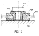
- the mounting lug 100 of the column is taken between two plastic pads 101, crossed by a metal insert 102.
- the fixing screw 103 on vehicle presses on insert 102, which puts the assembly pads 101 and metal tab 100 in tension. Peak of detachment is dimensioned by the tension in the stack and the coefficient of friction.
- the purpose of the present invention is to provide an energy absorption device which avoids disadvantages described above, and which allows a easy and precise adjustment of the requested value of energy absorption.
- the spacer is arranged on the central portion provided with two lateral elements, whose two axes of deformation are substantially perpendicular to the folding axis, the means of fixing consisting of a fixing screw, which mounts directly into the vehicle structure.
- the central portion not provided with lateral elements, has at least one relatively retaining element flexible which is made of the same metal sheet than said central portion.
- Said element of support revolves around a support axis located on the side of said central portion, so that in the free state, said holding element has its end which approaches the other portion central, and that after mounting on the support assembly, said end engages in a slot in the support assembly to ensure the installation and maintaining the energy absorption capsule on the support assembly before mounting in the vehicle automobile, the holding element being mounted against the bearing face of the structure.
- the central portion not provided of side elements has two elements of support whose support axis is substantially parallel to the folding axis.
- the energy absorption capsule is arranged on the support assembly so that the axis of folding is substantially perpendicular to the direction of force due to shock.
- the opening of passage of the fixing element, which is arranged on the support assembly is elongated and opens out into the direction of the force due to the shock, to allow disengagement of the capsule from the support assembly.
- the slot, which is arranged in the support assembly, is extended by a slight indentation, to ensure the release of the holding element in the event of shock.
- the energy absorption capsule is placed on the support assembly so that the folding axis be substantially parallel to the direction of the force due to shock.
- the passage hole of the element fixing which is arranged on the support assembly, is lying in the direction of the force due to the shock, to allow the energy absorption run.
- the slot which is arranged in the support assembly, is extended by a gently sloping chamfer, directed in the direction of the force due to the shock, in order to ensure the release of the holding element in the event of shock.
- the steering column has two capsules of energy absorption which are arranged on the side and on the other side of the vertical plane passing through the axis of direction, and whose folding axis is substantially perpendicular to the direction of the force due to shock.
- the steering column has two capsules of energy absorption, which are arranged on the side and on the other side of the vertical plane passing through the axis of direction, and whose folding axis is substantially parallel to the direction of the force due to the shock.
- the steering column has, in addition to the two bend axis energy absorption capsules substantially perpendicular to the direction of impact, two folding-axis energy absorption capsules substantially parallel to the direction of the shock and which are arranged on either side of the vertical plane passing through the steering axis.
- each group of two energy absorption capsules has two identical capsules, which are arranged symmetrically to each other by relation to the vertical plane passing through the axis of direction.
- the energy absorption device of a steering column thus presents the advantage of allowing the element to slide mobile support in the fixed support element with a controlled effort.
- the assembly and maintenance of capsules on the steering column is carried out in factory and it is independent of mounting on the vehicle.
- the invention makes it possible to have possibly only one capsule model produced in very large series, which can be mounted in parallel or perpendicular to the direction of the force due to shock.
- the operation is robust over time and in temperature, the energy absorption capsule being designed so as to remain within an area of elastic deformation.
- the energy absorption device according to the invention relates more particularly to a motor vehicle steering column.
- the steering column is still consisting of a steering shaft, which rotates around a direction axis.
- This direction tree is rotatably mounted in a body tube.
- the body tube is arranged in a set support, which is fixed to the structure of the vehicle.
- This support assembly comprises a support plate 1 which is connected to the vehicle structure and remains fixed relative to this structure when in use normal vehicle. It's only during a shock that the support plate 1 moves relative to the vehicle structure through the system energy absorption.
- the steering column is only represented by the support plate 1, which is drawn in Figures 3 to 13.
- the vertical plane passing through the direction axis cuts the support plate 1 shown completely and schematically in Figure 13 along an axis referenced 4.
- the support plate 1 is connected and secured to the structure of the vehicle by fixing means constituted by fixing screws 59 each having their fixing axis 60, as shown in Figures 6 and 13.
- At least one screw fixation 59 which includes an absorption capsule energy 10, which is arranged in the support plate 1 of the support assembly along the fixing axis 60.
- the energy absorption capsule 10 is clamped in the support plate 1 using the fixing screw 59, to be applied against the bearing face 9 of the vehicle structure.
- the energy absorption capsule 10 is shown in perspective in Figures 1 and 2.
- the energy absorption capsule 10 includes a central element 11 and two lateral elements 13 and 14 which are made from the same sheet metal element metallic.
- the central element 11 is constituted by the sheet folded 180 ° with a fold 12 extending by two central portions: a first portion central 17 and a second central portion 18.
- the fold 12 has a determined radius of curvature around a folding axis 22.
- the first central portion 17 has two sides 27 and 28, and the second central portion 18 has two sides 29 and 30.
- the lateral element 13 is made on side 27 of the first portion central 17, and it revolves around an axis of deformation 23 which is located nearby or which is merges with said side 27.
- the lateral element 14 is made on side 28 of the first portion central 17, and it revolves around an axis of deformation 24, which is located nearby or which is merges with said side 28.
- the end 33 of the lateral element 13 and the end 34 of the side element 14 approach the second central portion 18.
- the two axes of deformation 23 and 24 are substantially perpendicular to the folding axis 22.
- the two central portions 17 and 18 have each a corresponding passage hole 19 and 20 of the fixing screw 59.
- the first central portion 17 is provided with a spacer 21 arranged around the through hole 19 of the fixing screw 59.
- the length of the spacer 21 is determined so, only after fixing the absorption capsule energy 10 with the support assembly on the structure of the vehicle, the spacer 21 is applied against the internal face 39 of the second central portion 18, by compressing the two lateral elements 13 and 14 to the desired value.
- the fixing screw 59 blocks the energy absorption capsule 10 on the plate support 1, based on the external face 38 of the first central portion 17, while the face external 40 of the second central portion 18 is applied against the bearing face 9 of the structure.
- the two side elements 13 and 14 are compressed between the internal face 37 of the first portion central 17 and the underside 3 of the plate support 1, while the upper face 2 applies against the inner face 39 of the second portion central 18.
- the second central portion 18 has two relatively flexible retaining elements 15 and 16 which are made of the same metal sheet as said central portion 18.
- Each element of holding 15 and 16 revolves around an axis of corresponding support 25, 26 which is located on the corresponding side 29, 30 of said central portion 18.
- each holding element 15 and 16 has its corresponding end 35 and 36 which is approximates the first central portion 17.
- each end 35, 36 engages in a slot in the support plate 1 to ensure the installation and maintenance of the energy absorption capsule 10 on the support plate 1 before mounting in the vehicle automobile, the holding elements 15 and 16 being mounted against the bearing face 9 of the structure.
- the retaining axis 25 and 26 is substantially parallel to the folding axis 22.
- the energy absorption capsule 10 is placed on the support plate 1 so that the folding axis 22 either substantially perpendicular to the direction of force due to shock.
- a passage opening 41 of the fixing screw 59 is arranged on the plate support 1. The opening 41 is elongated and opens out in the direction of the force due to the shock, for allow the disengagement of the capsule 10 from the support plate 1.
- the passage opening 41 has two sides 43 and 44 which approach each other towards a background 42.
- a slot 45 and 46 is provided on the face upper 2 of the support plate 1, on both sides other than opening 41 so as to receive the corresponding end 35 and 36 of the element of maintenance 15 and 16.
- Slot 45 is extended by a slight recess 47 in order to ensure the release of the holding element 15 in the event of an impact.
- the slot 46 is extended by a slight recess 48 for the release of the element of maintenance 16.
- the energy absorption capsule 10 is placed on the support plate 1 so that the folding axis 22 be substantially parallel to the direction of the force due to shock.
- the passage hole 50 of the screw fixing 59 is arranged on the support plate 1.
- the through hole 50 is elongated in the direction of the force due to the shock, to allow the race energy absorption.
- the through hole 50 is elongated with two sides 51 and 52, and two rounded ends 53 and 54.
- a slot 55 and 56 is provided on the face upper 2 of the support plate 1, along the side corresponding to said support plate and between said side and side 51 of through hole 50.
- the slots 55 and 56 are arranged to receive the corresponding end 35 and 36 of the element of holding 15 and 16.
- the slot 55 is extended by a chamfer 57 with slight slope, directed in the direction force due to impact, in order to ensure the release of the holding element 15 in the event of an impact.
- the slot 56 is extended by a chamfer 58 with a slight slope for the release of the element maintenance 16.
- the establishment of the absorption capsule of energy 10 on the support plate 1 is thus secured in one direction by the stopper of the spacer 21 on the side 52 of the through hole 50.
- the setting place is ensured in the other direction by the stop of the ends 35 and 36 of the holding elements 15 and 16 against slots 55 and 56.
- the support plate 1 shown in Figure 13 contains 4 energy absorption capsules 10.
- Two 10 energy absorption capsules are arranged on either side of the vertical plane 4 passing through the steering axis. They have the axis of folding 22, which is substantially perpendicular to the direction of force due to shock. They are committed on the rear side 6 of the support plate 21 on the side of the steering wheel.
- Two 10 energy absorption capsules are arranged on either side of the vertical plane 4 passing through the steering axis. They have the axis of folding 22, which is substantially parallel to the direction of force due to shock. They are committed respectively on side 7 and 8 of the plate support 1 which is parallel to the vertical plane 4.
- Each group of two absorption capsules Energy 10 has two identical capsules, which are symmetrically arranged one with respect to the other relative to the vertical plane 4 passing through the steering axis.
- the side elements 13 and 14 provide the sliding force required between the capsule of energy absorption 10 and the support plate 1, and they deform around an axis 23 and 24 perpendicular to the folding axis 22 of the capsule 10. Their stiffness is k1.
- the holding elements 15 and 16 are used to hold the capsules in position 10 during the transport. Their stiffness is k2. They can deform around a parallel axis 25, 26 to the folding axis 22 of the capsule 10.
- the condition function is: k1 »k2.
- the energy absorption capsule 10 must ability to be retained on the steering column during transport before mounting the column steering in the vehicle.
- the holding elements 15 and 16 are deform and come to be housed in the slots 45 and 46 of the support plate 1.
- the stop of the capsule 10 on the support plate 1 is carried out in one direction by the contact of the spacer 21 and the plate support 1, and in the other direction by the abutment holding elements 15 and 16 in their slots 45 and 46 respectively.
- the fixing screw 59 tends to compress the capsule 10.
- the holding elements 15 and 16 being less rigid than the lateral elements 13 and 14, since k1 »k2, they deform first until flattened between the support plate 1 and the support face 9 of the vehicle.
- the system is designed so that when these elements are flattened, their ends 35 and 36 leave a clearance with the upper face 2 of the support plate 1. This game is guaranteed by the depth of recesses 47 and 48 positioned on the plate support 1.
- the sliding force of the capsules 10 is thus only dimensioned by the stiffness of the elements lateral 13 and 14, their stress rate once climbs, and the coefficient of friction between the capsule 10 and the support plate 1.
- the energy absorption capsule 10 is made of a metal sheet.
- the sheet used whose thickness can vary depending on the effort of desired slip, is a sheet with high limit elastic.
- the capsule 10, once mounted, must stay in its elastic deformation domain.
- disengagement system 10 can be added guidance and absorption system of energy, using the same 10 capsule in one different configuration shown in the figures 9 to 12.
- the sliding direction is perpendicular to the mounting direction.
- the support plate 1 on which the capsule 10 is fixed is the even, the principle of behavior during transport and deformation at assembly is the same.
Abstract
Description
La présente invention se rapporte à un dispositif d'absorption d'énergie d'une colonne de véhicule automobile. La colonne de direction est montée dans un ensemble support qui est relié et solidarisé à la structure du véhicule par des moyens de fixation, avec au moins une capsule d'absorption d'énergie disposée sur l'un des moyens de fixation.The present invention relates to a energy absorption device of a column of motor vehicle. The steering column is mounted in a support assembly which is connected and secured to the vehicle structure by means fixation, with at least one absorption capsule of energy disposed on one of the fixing means.
Il existe des colonnes de direction qui ont une ou plusieurs capsules d'absorption d'énergie qui sont montées directement selon l'/les axe(s) de fixation. L'absorption d'énergie de chaque capsule dépend donc du serrage de l'ensemble support sur la structure du véhicule.There are steering columns that have a or more energy absorption capsules which are mounted directly along the fixing axis (s). The energy absorption of each capsule therefore depends tightening of the support assembly on the structure of the vehicle.
Parmi les solutions les plus répandues assurant le désengagement des corps de colonne, on retrouve des capsules injectées et des capsules plastiques.Among the most widespread solutions ensuring the disengagement of the column bodies, we find injected capsules and plastic capsules.
Dans les capsules injectées, du plastique est injecté à l'interface entre la capsule et une zone de la patte de fixation. Lorsqu'un effort suffisant est appliqué à la patte, les pions de plastique injecté sont cisaillés et la patte se désengage des capsules, liées au support véhicule. L'effort de désengagement relatif est lié au diamètre des pions cisaillés.In the injected capsules, plastic is injected at the interface between the capsule and a zone of the mounting lug. When sufficient effort is applied to the tab, the injected plastic pieces are sheared and the tab disengages from the capsules, related to vehicle support. The disengagement effort relative is related to the diameter of the sheared pins.
Dans les capsules plastiques représentées à la
figure 14, la patte de fixation 100 de la colonne est
prise entre deux patins plastiques 101, traversés par
un insert métallique 102. La vis de fixation 103 sur
véhicule appuie sur l'insert 102, qui met l'ensemble
patins 101 et patte métallique 100 en tension. Le pic
de décollement est dimensionné par la tension dans
l'empilement et le coefficient de frottement.In the plastic capsules shown in the
Figure 14, the
Dans la fabrication en grande série, comme c'est le cas dans l'industrie automobile, il est difficile de réaliser et de garantir un serrage précis et constant de la fixation et donc de la pression de serrage de la ou des capsules d'absorption d'énergie. Comme l'absorption d'énergie de ces capsules dépend directement de ce serrage, il en résultera une absorption d'énergie imprécise. Mais dans les véhicules automobiles actuels et futurs, il est de plus en plus impératif que les caractéristiques de sécurité passive soient précises et efficaces.In mass production, as is the case in the automotive industry it's difficult to achieve and guarantee precise tightening and constant of the fixation and therefore of the pressure of tightening of the energy absorption capsule (s). As the energy absorption of these capsules depends directly from this tightening, it will result in a imprecise energy absorption. But in the current and future motor vehicles it's increasingly imperative that the characteristics of passive safety are precise and effective.
Le but de la présente invention est de proposer un dispositif d'absorption d'énergie qui évite les inconvénients décrits ci-dessus, et qui permet un réglage facile et précis de la valeur demandée de l'absorption d'énergie.The purpose of the present invention is to provide an energy absorption device which avoids disadvantages described above, and which allows a easy and precise adjustment of the requested value of energy absorption.
L'invention s'applique à un dispositif d'absorption d'énergie d'une colonne de direction de véhicule automobile, qui est montée dans un ensemble support relié et solidarisé à la structure du véhicule par des moyens de fixation, qui ont chacun leur axe de fixation, et qui peuvent comporter une capsule d'absorption d'énergie, en tôle métallique, disposée et serrée dans ledit ensemble support par le moyen de fixation. Ce dispositif est caractérisé en ce que :
- ledit dispositif est muni d'au moins une capsule d'absorption d'énergie qui comporte un élément central et deux éléments latéraux ;
- l'élément central est constitué par une partie pliée à 180 ° avec une pliure se prolongeant par deux portions centrales, ladite pliure ayant un rayon de courbure déterminé autour d'un axe de pliage ;
- chacun des deux éléments latéraux est réalisé sur chacun des deux côtés de la portion centrale, il s'articule autour d'un axe de déformation sensiblement perpendiculaire à l'axe de pliage et situé à proximité du côté correspondant de manière, qu'à l'état libre, l'extrémité de chaque élément latéral se rapproche de l'autre portion centrale ;
- les deux portions centrales possèdent chacune un trou de passage de l'élément de fixation ;
- l'une des deux portions centrales est munie d'une entretoise avec un trou de passage de l'élément de fixation et dont la longueur est déterminée de manière, qu'après fixation de la capsule d'absorption d'énergie avec l'ensemble support sur la structure du véhicule, l'entretoise s'applique contre l'autre portion centrale en comprimant les deux éléments latéraux à la valeur voulue.
- said device is provided with at least one energy absorption capsule which comprises a central element and two lateral elements;
- the central element consists of a part folded at 180 ° with a fold extending by two central portions, said fold having a radius of curvature determined around a folding axis;
- each of the two lateral elements is produced on each of the two sides of the central portion, it is articulated around a deformation axis substantially perpendicular to the folding axis and located near the corresponding side so that at the 'free state, the end of each side element approaches the other central portion;
- the two central portions each have a hole for passage of the fixing element;
- one of the two central portions is provided with a spacer with a hole for passage of the fixing element and the length of which is determined so that only after fixing the energy absorption capsule with the assembly support on the vehicle structure, the spacer is applied against the other central portion by compressing the two side elements to the desired value.
Préférablement, l'entretoise est agencée sur la portion centrale munie des deux éléments latéraux, dont les deux axes de déformation sont sensiblement perpendiculaires à l'axe de pliage, le moyen de fixation étant constitué par une vis de fixation, qui se monte directement dans la structure du véhicule.Preferably, the spacer is arranged on the central portion provided with two lateral elements, whose two axes of deformation are substantially perpendicular to the folding axis, the means of fixing consisting of a fixing screw, which mounts directly into the vehicle structure.
Selon un mode de réalisation de l'invention, la portion centrale, non munie d'éléments latéraux, comporte au moins un élément de maintien relativement flexible qui est réalisé dans la même tôle métallique que ladite portion centrale. Ledit élément de maintien s'articule autour d'un axe de maintien situé sur le côté de ladite portion centrale, de manière, qu'à l'état libre, ledit élément de maintien a son extrémité qui se rapproche de l'autre portion centrale, et qu'après montage sur l'ensemble support, ladite extrémité s'engage dans une fente aménagée dans l'ensemble support pour assurer la mise en place et le maintien de la capsule d'absorption d'énergie sur l'ensemble support avant montage dans le véhicule automobile, l'élément de maintien étant monté contre la face d'appui de la structure.According to one embodiment of the invention, the central portion, not provided with lateral elements, has at least one relatively retaining element flexible which is made of the same metal sheet than said central portion. Said element of support revolves around a support axis located on the side of said central portion, so that in the free state, said holding element has its end which approaches the other portion central, and that after mounting on the support assembly, said end engages in a slot in the support assembly to ensure the installation and maintaining the energy absorption capsule on the support assembly before mounting in the vehicle automobile, the holding element being mounted against the bearing face of the structure.
Préférablement, la portion centrale non munie d'éléments latéraux comporte deux éléments de maintien dont l'axe de maintien est sensiblement parallèle à l'axe de pliage.Preferably, the central portion not provided of side elements has two elements of support whose support axis is substantially parallel to the folding axis.
Selon une première architecture de l'invention, la capsule d'absorption d'énergie est disposée sur l'ensemble support de manière que l'axe de pliage soit sensiblement perpendiculaire à la direction de la force due au choc. L'ouverture de passage de l'élément de fixation, qui est agencée sur l'ensemble support, est allongée et débouchante dans la direction de la force due au choc, pour permettre le désengagement de la capsule de l'ensemble support. La fente, qui est aménagée dans l'ensemble support, se prolonge par un léger renfoncement, afin d'assurer le dégagement de l'élément de maintien en cas de choc.According to a first architecture of the invention, the energy absorption capsule is arranged on the support assembly so that the axis of folding is substantially perpendicular to the direction of force due to shock. The opening of passage of the fixing element, which is arranged on the support assembly, is elongated and opens out into the direction of the force due to the shock, to allow disengagement of the capsule from the support assembly. The slot, which is arranged in the support assembly, is extended by a slight indentation, to ensure the release of the holding element in the event of shock.
Selon une deuxième architecture de l'invention, la capsule d'absorption d'énergie est disposée sur l'ensemble support de manière que l'axe de pliage soit sensiblement parallèle à la direction de la force due au choc. Le trou de passage de l'élément de fixation, qui est agencé sur l'ensemble support, est allongé dans la direction de la force due au choc, pour permettre la course d'absorption d'énergie. La fente, qui est aménagée dans l'ensemble support, se prolonge par un chanfrein à faible pente, dirigé dans la direction de la force due au choc, afin d'assurer le dégagement de l'élément de maintien en cas de choc.According to a second architecture of the invention, the energy absorption capsule is placed on the support assembly so that the folding axis be substantially parallel to the direction of the force due to shock. The passage hole of the element fixing, which is arranged on the support assembly, is lying in the direction of the force due to the shock, to allow the energy absorption run. The slot, which is arranged in the support assembly, is extended by a gently sloping chamfer, directed in the direction of the force due to the shock, in order to ensure the release of the holding element in the event of shock.
Dans un premier agencement de l'invention, la colonne de direction comporte deux capsules d'absorption d'énergie qui sont disposées de part et d'autre du plan vertical passant par l'axe de direction, et dont l'axe de pliage est sensiblement perpendiculaire à la direction de la force due au choc.In a first arrangement of the invention, the steering column has two capsules of energy absorption which are arranged on the side and on the other side of the vertical plane passing through the axis of direction, and whose folding axis is substantially perpendicular to the direction of the force due to shock.
Dans un deuxième agencement de l'invention, la colonne de direction comporte deux capsules d'absorption d'énergie, qui sont disposées de part et d'autre du plan vertical passant par l'axe de direction, et dont l'axe de pliage est sensiblement parallèle à la direction de la force due au choc.In a second arrangement of the invention, the steering column has two capsules of energy absorption, which are arranged on the side and on the other side of the vertical plane passing through the axis of direction, and whose folding axis is substantially parallel to the direction of the force due to the shock.
Dans un troisième agencement de l'invention, la colonne de direction comporte, en plus des deux capsules d'absorption d'énergie à axe de pliage sensiblement perpendiculaire à la direction du choc, deux capsules d'absorption d'énergie à axe de pliage sensiblement parallèle à la direction du choc et qui sont disposées de part et d'autre du plan vertical passant par l'axe de direction.In a third arrangement of the invention, the steering column has, in addition to the two bend axis energy absorption capsules substantially perpendicular to the direction of impact, two folding-axis energy absorption capsules substantially parallel to the direction of the shock and which are arranged on either side of the vertical plane passing through the steering axis.
Dans ces trois agencements de l'invention, chaque groupe de deux capsules d'absorption d'énergie comporte deux capsules identiques, qui sont disposées symétriquement l'une par rapport à l'autre par rapport au plan vertical passant par l'axe de direction.In these three arrangements of the invention, each group of two energy absorption capsules has two identical capsules, which are arranged symmetrically to each other by relation to the vertical plane passing through the axis of direction.
Le dispositif d'absorption d'énergie d'une colonne de direction selon l'invention présente ainsi l'avantage de permettre un glissement de l'élément support mobile dans l'élément support fixe avec un effort maítrisé. Le montage et le maintien des capsules sur la colonne de direction est effectué en usine et il est indépendant du montage sur le véhicule. De plus, l'invention permet d'avoir éventuellement un seul modèle de capsule produit en très grande série, qui peut être montée parallèlement ou perpendiculairement à la direction de la force due au choc.The energy absorption device of a steering column according to the invention thus presents the advantage of allowing the element to slide mobile support in the fixed support element with a controlled effort. The assembly and maintenance of capsules on the steering column is carried out in factory and it is independent of mounting on the vehicle. In addition, the invention makes it possible to have possibly only one capsule model produced in very large series, which can be mounted in parallel or perpendicular to the direction of the force due to shock.
Le type de capsule d'absorption d'énergie selon l'invention permet d'avoir, en cas de choc, un effort de glissement et donc une absorption d'énergie qui ne dépend pas du couple de serrage de la vis de fixation. La capsule offre avec une seule et même pièce deux fonctions :
- la fonction d'absorption d'énergie, et
- la fonction de maintien sur la colonne avant montage sur le véhicule et après une mise en place particulièrement simple.
- the energy absorption function, and
- the holding function on the column before mounting on the vehicle and after a particularly simple installation.
Le fonctionnement est robuste dans le temps et en température, la capsule d'absorption d'énergie étant conçue de manière à rester dans un domaine de déformation élastique.The operation is robust over time and in temperature, the energy absorption capsule being designed so as to remain within an area of elastic deformation.
D'autres caractéristiques et avantages de la présente invention apparaítront plus clairement à la lecture de la description suivante de plusieurs réalisations préférées de l'invention en référence aux dessins annexés correspondants dans lesquels :
- la figure 1 est une vue en perspective d'une capsule d'absorption d'énergie selon l'invention ;
- la figure 2 est une vue en perspective suivant II de la figure 1 ;
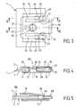
- la figure 3 est une vue suivant III de la figure 1, la capsule d'absorption étant montée sur l'ensemble support ;
- la figure 4 est une coupe suivant le plan IV-IV de la figure 3 ;
- la figure 5 est une coupe suivant le plan V-V de la figure 3 ;
- la figure 6 est une coupe analogue à la figure 4 avec la capsule d'absorption d'énergie fixée à la structure du véhicule ;
- la figure 7 est une coupe analogue à la figure 5 avec la capsule d'absorption d'énergie fixée à la structure du véhicule ;
- la figure 8 est une vue en perspective suivant VIII de la figure 5, l'ensemble support étant dans la zone de la capsule d'absorption d'énergie ;
- la figure 9 est une vue en perspective analogue à la figure 2, d'un autre montage de la capsule d'absorption d'énergie ;
- la figure 10 est une vue en perspective analogue à la figure 1 du montage de la figure 9 ;
- la figure 10A est une vue partielle à grande échelle de la figure 10 ;
- la figure 11 est une coupe suivant le plan XI-XI de la figure 10 ;
- la figure 12 est une coupe analogue à la figure 11, après fixation sur la structure du véhicule ;
- la figure 13 est une vue d'ensemble en perspective de l'ensemble support avec quatre capsules vues comme sur la figure 2, deux capsules sont disposées comme sur la figure 3, et deux capsules sont disposées comme sur la figure 9 ; et
- la figure 14 est une coupe de capsules plastiques connues.
- Figure 1 is a perspective view of an energy absorption capsule according to the invention;
- Figure 2 is a perspective view along II of Figure 1;
- Figure 3 is a view along III of Figure 1, the absorption capsule being mounted on the support assembly;
- Figure 4 is a section along the plane IV-IV of Figure 3;
- Figure 5 is a section along the plane VV of Figure 3;
- Figure 6 is a section similar to Figure 4 with the energy absorption capsule attached to the vehicle structure;
- Figure 7 is a section similar to Figure 5 with the energy absorption capsule attached to the vehicle structure;
- Figure 8 is a perspective view along VIII of Figure 5, the support assembly being in the region of the energy absorption capsule;
- Figure 9 is a perspective view similar to Figure 2, of another assembly of the energy absorption capsule;
- Figure 10 is a perspective view similar to Figure 1 of the assembly of Figure 9;
- Figure 10A is a partial enlarged view of Figure 10;
- Figure 11 is a section along the plane XI-XI of Figure 10;
- Figure 12 is a section similar to Figure 11, after attachment to the vehicle structure;
- Figure 13 is an overall perspective view of the support assembly with four capsules seen as in Figure 2, two capsules are arranged as in Figure 3, and two capsules are arranged as in Figure 9; and
- Figure 14 is a section of known plastic capsules.
Le dispositif d'absorption d'énergie selon l'invention se rapporte plus particulièrement à une colonne de direction de véhicule automobile.The energy absorption device according to the invention relates more particularly to a motor vehicle steering column.
Quel que soit le mode de réalisation possible de l'invention, la colonne de direction est toujours constituée par un arbre de direction, qui tourne autour d'un axe de direction. Cet arbre de direction est monté tournant dans un tube corps.Whatever the possible embodiment of the invention the steering column is still consisting of a steering shaft, which rotates around a direction axis. This direction tree is rotatably mounted in a body tube.
Le tube corps est disposé dans un ensemble
support, qui est fixé à la structure du véhicule. Cet
ensemble support comporte une plaque support 1 qui
est reliée à la structure du véhicule et reste fixe
par rapport à cette structure lors de l'utilisation
normale du véhicule. C'est seulement lors d'un choc
que la plaque support 1 se déplace par rapport à la
structure du véhicule par l'intermédiaire du système
d'absorption d'énergie. La colonne de direction est
seulement représentée par la plaque support 1, qui
est dessinée sur les figures 3 à 13.The body tube is arranged in a set
support, which is fixed to the structure of the vehicle. This
support assembly comprises a
Dans la suite de la description et pour un même élément, on appellera interne ou intérieur par rapport à l'axe de direction ou par rapport au plan vertical de cet axe de direction, ce qui est le plus près de cet axe ou de ce plan, et externe ou extérieur ce qui est le plus éloigné. Pour un même élément, on appellera avant ce qui est le plus près du boítier de direction non représenté, et arrière ce qui est le plus près du volant de direction également non représenté.In the following description and for the same element, we will call internal or internal by relative to the steering axis or relative to the plane vertical of this direction axis, which is the most near this axis or this plane, and external or outside which is furthest away. For the same element, we will call before which is the closest steering box not shown, and rear this which is closest to the steering wheel also not shown.
Le plan vertical passant par l'axe de direction
coupe la plaque support 1 représentée complètement et
schématiquement sur la figure 13 selon un axe
référencé 4.The vertical plane passing through the direction axis
cuts the
La plaque support 1 est reliée et solidarisée à
la structure du véhicule par des moyens de fixation
constitués par des vis de fixation 59 ayant chacune
leur axe de fixation 60, comme cela est représenté
aux figures 6 et 13.The
Selon l'invention, il y a au moins une vis de
fixation 59 qui comporte une capsule d'absorption
d'énergie 10, qui est disposée dans la plaque support
1 de l'ensemble support selon l'axe de fixation 60.
La capsule d'absorption d'énergie 10 est serrée dans
la plaque support 1 à l'aide de la vis de fixation
59, pour venir s'appliquer contre la face d'appui 9
de la structure du véhicule.According to the invention, there is at least one
Dans le cas de la figure 13, il y a quatre
capsules d'absorption d'énergie 10.In the case of Figure 13, there are four
La capsule d'absorption d'énergie 10 est
représentée en perspective sur les figures 1 et 2.The
La capsule d'absorption d'énergie 10 comporte un
élément central 11 et deux éléments latéraux 13 et 14
qui sont réalisés dans le même élément de tôle
métallique.The
L'élément central 11 est constitué par la tôle
pliée à 180 ° avec une pliure 12 se prolongeant par
deux portions centrales : une première portion
centrale 17 et une deuxième portion centrale 18. La
pliure 12 a un rayon de courbure déterminé autour
d'un axe de pliage 22.The
La première portion centrale 17 possède deux
côtés 27 et 28, et la deuxième portion centrale 18
possède deux côtés 29 et 30. L'élément latéral 13 est
réalisé sur le côté 27 de la première portion
centrale 17, et il s'articule autour d'un axe de
déformation 23 qui est situé à proximité ou qui se
confond avec ledit côté 27. L'élément latéral 14 est
réalisé sur le côté 28 de la première portion
centrale 17, et il s'articule autour d'un axe de
déformation 24, qui est situé à proximité ou qui se
confond avec ledit côté 28. A l'état libre,
l'extrémité 33 de l'élément latéral 13 et l'extrémité
34 de l'élément latéral 14 se rapprochent de la
deuxième portion centrale 18. Les deux axes de
déformation 23 et 24 sont sensiblement
perpendiculaires à l'axe de pliage 22. The first
Les deux portions centrales 17 et 18 possèdent
chacune un trou de passage correspondant 19 et 20 de
la vis de fixation 59.The two
Comme on peut le voir sur les figures 4 et 6, la
première portion centrale 17 est munie d'une
entretoise 21 agencée autour du trou de passage 19 de
la vis de fixation 59. Selon l'invention, la longueur
de l'entretoise 21 est déterminée de manière,
qu'après fixation de la capsule d'absorption
d'énergie 10 avec l'ensemble support sur la structure
du véhicule, l'entretoise 21 s'applique contre la
face interne 39 de la deuxième portion centrale 18,
en comprimant les deux éléments latéraux 13 et 14 à
la valeur voulue. La vis de fixation 59 bloque la
capsule d'absorption d'énergie 10 sur la plaque
support 1, en s'appuyant sur la face externe 38 de la
première portion centrale 17, tandis que la face
externe 40 de la deuxième portion centrale 18
s'applique contre la face d'appui 9 de la structure.
Les deux éléments latéraux 13 et 14 sont comprimés
entre la face interne 37 de la première portion
centrale 17 et la face inférieure 3 de la plaque
support 1, tandis que la face supérieure 2 s'applique
contre la face interne 39 de la deuxième portion
centrale 18.As can be seen in Figures 4 and 6, the
first
La deuxième portion centrale 18 comporte deux
éléments de maintien 15 et 16 relativement flexibles
qui sont réalisés dans la même tôle métallique que
ladite portion centrale 18. Chaque élément de
maintien 15 et 16 s'articule autour d'un axe de
maintien correspondant 25, 26 qui est situé sur le
côté correspondant 29, 30 de ladite portion centrale
18. A l'état libre, chaque élément de maintien 15 et
16 a son extrémité correspondante 35 et 36 qui se
rapproche de la première portion centrale 17. Après
montage sur l'ensemble support 1, chaque extrémité
35, 36 s'engage dans une fente aménagée dans la
plaque support 1 pour assurer la mise en place et le
maintien de la capsule d'absorption d'énergie 10 sur
la plaque support 1 avant montage dans le véhicule
automobile, les éléments de maintien 15 et 16 étant
montés contre la face d'appui 9 de la structure.The second
L'axe de maintien 25 et 26 est sensiblement
parallèle à l'axe de pliage 22.The retaining
Dans le montage de la capsule d'absorption
d'énergie 10 représenté sur les figures 3 à 8, la
capsule d'absorption d'énergie 10 est disposée sur la
plaque support 1 de manière que l'axe de pliage 22
soit sensiblement perpendiculaire à la direction de
la force due au choc. Une ouverture de passage 41 de
la vis de fixation 59 est agencée sur la plaque
support 1. L'ouverture 41 est allongée et débouchante
dans la direction de la force due au choc, pour
permettre le désengagement de la capsule 10 de la
plaque support 1.In the assembly of the
L'ouverture de passage 41 comporte deux côtés 43
et 44 qui se rapprochent l'un de l'autre vers un fond
42. Une fente 45 et 46 est aménagée sur la face
supérieure 2 de la plaque support 1, de part et
d'autre de l'ouverture 41 de manière à recevoir
l'extrémité correspondante 35 et 36 de l'élément de
maintien 15 et 16.The
La fente 45 se prolonge par un léger
renfoncement 47 afin d'assurer le dégagement de
l'élément de maintien 15 en cas de choc. De la même
façon, la fente 46 se prolonge par un léger
renfoncement 48 pour le dégagement de l'élément de
maintien 16. La mise en place de la capsule
d'absorption d'énergie 10 sur la plaque support 1 est
ainsi assurée dans un sens par la butée de
l'entretoise 21 entre les côtés inclinés 43 et 44 de
l'ouverture de passage 41. La mise en place est
assurée dans l'autre sens par la butée des extrémités
35 et 36 des éléments de maintien 15 et 16 contre les
fentes 45 et 46.
Dans le montage de la capsule d'absorption
d'énergie 10 représenté sur les figures 9 à 12, la
capsule d'absorption d'énergie 10 est disposée sur la
plaque support 1 de manière que l'axe de pliage 22
soit sensiblement parallèle à la direction de la
force due au choc. Le trou de passage 50 de la vis de
fixation 59 est agencé sur la plaque support 1. Le
trou de passage 50 est allongé dans la direction de
la force due au choc, pour permettre la course
d'absorption d'énergie.In the assembly of the
Le trou de passage 50 est allongé avec deux
cotés 51 et 52, et deux extrémités arrondies 53 et
54.The through
Une fente 55 et 56 est aménagée sur la face
supérieure 2 de la plaque support 1, le long du côté
correspondant de ladite plaque support et entre ledit
côté et le côté 51 du trou de passage 50. Les fentes
55 et 56 sont aménagées de manière à recevoir
l'extrémité correspondante 35 et 36 de l'élément de
maintien 15 et 16. La fente 55 se prolonge par un
chanfrein 57 à faible pente, dirigé dans la direction
de la force due au choc, afin d'assurer le dégagement
de l'élément de maintien 15 en cas de choc. De la
même façon, la fente 56 se prolonge par un chanfrein
58 à faible pente pour le dégagement de l'élément de
maintien 16.A
La mise en place de la capsule d'absorption
d'énergie 10 sur la plaque support 1 est ainsi
assurée dans un sens par la butée de l'entretoise 21
sur le côté 52 du trou de passage 50. La mise en
place est assurée dans l'autre sens par la butée des
extrémités 35 et 36 des éléments de maintien 15 et 16
contre les fentes 55 et 56.The establishment of the absorption capsule
of
La plaque support 1 représentée sur la figure 13
comporte 4 capsules d'absorption d'énergie 10.The
Deux capsules d'absorption d'énergie 10 sont
disposées de part et d'autre du plan vertical 4
passant par l'axe de direction. Elles ont l'axe de
pliage 22, qui est sensiblement perpendiculaire à la
direction de la force due au choc. Elles s'engagent
sur le côté arrière 6 de la plaque-support 21 du côté
du volant.Two 10 energy absorption capsules are
arranged on either side of the vertical plane 4
passing through the steering axis. They have the axis of
folding 22, which is substantially perpendicular to the
direction of force due to shock. They are committed
on the rear side 6 of the
Deux capsules d'absorption d'énergie 10 sont
disposées de part et d'autre du plan vertical 4
passant par l'axe de direction. Elles ont l'axe de
pliage 22, qui est sensiblement parallèle à la
direction de la force due au choc. Elles s'engagent
respectivement sur le côté 7 et 8 de la plaque
support 1 qui est parallèle au plan vertical 4.Two 10 energy absorption capsules are
arranged on either side of the vertical plane 4
passing through the steering axis. They have the axis of
folding 22, which is substantially parallel to the
direction of force due to shock. They are committed
respectively on
Chaque groupe de deux capsules d'absorption
d'énergie 10 comporte deux capsules identiques, qui
sont disposées symétriquement l'une par rapport à
l'autre par rapport au plan vertical 4 passant par
l'axe de direction.Each group of two
Les éléments latéraux 13 et 14 fournissent
l'effort de glissement voulu entre la capsule
d'absorption d'énergie 10 et la plaque-support 1, et
ils se déforment autour d'un axe 23 et 24
perpendiculaire à l'axe de pliage 22 de la capsule
10. Leur raideur est k1. Les éléments de maintien 15
et 16 servent au maintien en position des capsules 10
pendant le transport. Leur raideur est k2. Ils
peuvent se déformer autour d'un axe 25, 26 parallèle
à l'axe de pliage 22 de la capsule 10. La condition
de fonction est : k1»k2. The
La capsule d'absorption d'énergie 10 doit
pouvoir être retenue sur la colonne de direction
pendant le transport avant montage de la colonne de
direction dans le véhicule.The
Lorsque la capsule 10 est montée sur la plaque
support 1, les éléments de maintien 15 et 16 se
déforment et viennent se loger dans les fentes 45 et
46 de la plaque support 1. La butée de la capsule 10
sur la plaque support 1 est effectuée dans un sens
par le contact de l'entretoise 21 et de la plaque
support 1, et dans l'autre sens par la mise en butée
des éléments de maintien 15 et 16 dans leurs fentes
respectives 45 et 46.When the
Lorsque la colonne de direction est fixée sur
son support véhicule, la vis de fixation 59 tend à
comprimer la capsule 10. Les éléments de maintien 15
et 16 étant moins rigides que les éléments latéraux
13 et 14, puisque k1»k2, ils se déforment d'abord
jusqu'à s'aplatir entre la plaque support 1 et la
face d'appui 9 du véhicule.When the steering column is fixed to
its vehicle support, the fixing
Une fois les éléments de maintien 15 et 16
aplatis, les éléments latéraux 13 et 14 plient
jusqu'à ce que l'extrémité de l'entretoise 21 vienne
buter contre la partie opposée de la capsule 10.After holding
Afin d'éviter que les éléments de maintien 15 et
16 interfèrent avec la plaque support 1 en cas de
désengagement de la colonne de direction dû à un
choc, le système est conçu de sorte que lorsque ces
éléments sont aplatis, leur extrémité 35 et 36 laisse
un jeu avec la face supérieure 2 de la plaque support
1. Ce jeu est garanti par la profondeur des
renfoncements 47 et 48 positionnés sur la plaque
support 1.In order to prevent the holding
L'effort de glissement des capsules 10 est ainsi
uniquement dimensionné par la raideur des éléments
latéraux 13 et 14, leur taux de contrainte une fois
montées, et le coefficient de frottement entre la
capsule 10 et la plaque support 1.The sliding force of the
La capsule d'absorption d'énergie 10 est
réalisée dans une tôle métallique. La tôle utilisée,
dont l'épaisseur peut varier selon l'effort de
glissement voulu, est une tôle à haute limite
élastique. La capsule 10, une fois montée, doit
rester dans son domaine de déformation élastique.The
Dans le cas des figures 3 à 8, le sens de
montage de la capsule 10 et la direction de
glissement sont parallèles, et la capsule 10 assure
une fonction de désengagement "fusible" de la colonne
de direction. La zone de frottement est limitée et la
courbe d'effort s'apparente à une montée très
importante et brutale.In the case of Figures 3 to 8, the direction of
mounting of the
A ce système de désengagement 10 peut être
ajouté un système de guidage et d'absorption
d'énergie, utilisant la même capsule 10 dans une
configuration différente représentée sur les figures
9 à 12. Dans ce cas, la direction de glissement est
perpendiculaire au sens de montage. La plaque support
1 sur laquelle vient se fixer la capsule 10 est la
même, le principe de tenue pendant le transport et de
déformation à l'assemblage est le même.At this
Les seules différences résident dans :
- l'obtention du jeu fonctionnel garantissant le
non blocage de la colonne de direction et donnée par
des chanfreins à faible pente 57
et 58 ; - la perpendicularité entre direction de glissement et la direction de montage ; et
- la fonction de guidage et d'absorption
d'énergie assurée par
la capsule 10 sur la course lors du choc.
- obtaining the functional clearance guaranteeing the non-locking of the steering column and given by bevels with a
slight slope - the perpendicularity between sliding direction and mounting direction; and
- the function of guiding and absorbing energy provided by the
capsule 10 on the stroke during the impact.
Les principaux avantages de ce type de capsule 10 sont les suivants :
- l'effort de glissement ne dépend pas du couple
de serrage des vis de
fixation 59, - la mise en place de la
capsule 10 est simple, les deux fonctions recherchées sont remplies avec une seule pièce ; et - le fonctionnement est robuste dans le temps et
en température,
la capsule 10 est conçue de manière à rester dans un domaine de déformation élastique.
- the sliding force does not depend on the tightening torque of the fixing screws 59,
- the establishment of the
capsule 10 is simple, the two desired functions are fulfilled with a single piece; and - the operation is robust over time and in temperature, the
capsule 10 is designed so as to remain in an area of elastic deformation.
Claims (10)
Applications Claiming Priority (2)
| Application Number | Priority Date | Filing Date | Title |
|---|---|---|---|
| FR0306001A FR2855141B1 (en) | 2003-05-19 | 2003-05-19 | DEFORMABLE METAL CAPSULE DEVICE OF A POWER ABSORPTION SYSTEM OF A STEERING COLUMN OF A MOTOR VEHICLE |
| FR0306001 | 2003-05-19 |
Publications (1)
| Publication Number | Publication Date |
|---|---|
| EP1479592A1 true EP1479592A1 (en) | 2004-11-24 |
Family
ID=33041997
Family Applications (1)
| Application Number | Title | Priority Date | Filing Date |
|---|---|---|---|
| EP04291129A Withdrawn EP1479592A1 (en) | 2003-05-19 | 2004-05-03 | Device with deformable metallic inserts of a motor vehicle steering column energy absorption system |
Country Status (3)
| Country | Link |
|---|---|
| EP (1) | EP1479592A1 (en) |
| JP (1) | JP3945495B2 (en) |
| FR (1) | FR2855141B1 (en) |
Cited By (4)
| Publication number | Priority date | Publication date | Assignee | Title |
|---|---|---|---|---|
| EP1775195A2 (en) * | 2005-10-17 | 2007-04-18 | Delphi Technologies, Inc. | Steering column mounting |
| FR2931439A1 (en) * | 2008-05-21 | 2009-11-27 | Peugeot Citroen Automobiles Sa | FIXING DEVICE BETWEEN TWO ELEMENTS THAT COULD SLIDE IN RELATION TO THE OTHER IN CASE OF SHOCK |
| CN110775147A (en) * | 2018-07-31 | 2020-02-11 | 株式会社山田制作所 | Steering device |
| US11142239B2 (en) | 2016-07-07 | 2021-10-12 | ZF Steering Systems Poland Sp. Z.o.o. | Steering column assembly |
Families Citing this family (3)
| Publication number | Priority date | Publication date | Assignee | Title |
|---|---|---|---|---|
| JP5708839B2 (en) * | 2011-07-26 | 2015-04-30 | 日本精工株式会社 | Steering column support device |
| JP5898460B2 (en) * | 2011-11-01 | 2016-04-06 | 特許機器株式会社 | Air-conditioning equipment drop-off prevention bracket |
| US9669862B1 (en) * | 2016-02-18 | 2017-06-06 | Steering Solutions Ip Holding Corporation | Steering column having an energy absorption assembly |
Citations (3)
| Publication number | Priority date | Publication date | Assignee | Title |
|---|---|---|---|---|
| FR2623256A1 (en) * | 1987-11-17 | 1989-05-19 | Renault | Fixing device |
| JPH09264314A (en) * | 1996-03-28 | 1997-10-07 | Ichikoh Ind Ltd | Structure of fitting part of spring nut |
| DE10007145A1 (en) * | 1999-02-18 | 2000-08-24 | Yamada Seisakusho Kiryu Kk | Shock absorbing device for steering column of motor vehicle has sliding capsule with collar section which with collision of vehicle bends spike-form element in first shock absorbing section and presses into second section |
-
2003
- 2003-05-19 FR FR0306001A patent/FR2855141B1/en not_active Expired - Lifetime
-
2004
- 2004-05-03 EP EP04291129A patent/EP1479592A1/en not_active Withdrawn
- 2004-05-19 JP JP2004149090A patent/JP3945495B2/en not_active Expired - Fee Related
Patent Citations (3)
| Publication number | Priority date | Publication date | Assignee | Title |
|---|---|---|---|---|
| FR2623256A1 (en) * | 1987-11-17 | 1989-05-19 | Renault | Fixing device |
| JPH09264314A (en) * | 1996-03-28 | 1997-10-07 | Ichikoh Ind Ltd | Structure of fitting part of spring nut |
| DE10007145A1 (en) * | 1999-02-18 | 2000-08-24 | Yamada Seisakusho Kiryu Kk | Shock absorbing device for steering column of motor vehicle has sliding capsule with collar section which with collision of vehicle bends spike-form element in first shock absorbing section and presses into second section |
Non-Patent Citations (1)
| Title |
|---|
| PATENT ABSTRACTS OF JAPAN vol. 1998, no. 02 30 January 1998 (1998-01-30) * |
Cited By (6)
| Publication number | Priority date | Publication date | Assignee | Title |
|---|---|---|---|---|
| EP1775195A2 (en) * | 2005-10-17 | 2007-04-18 | Delphi Technologies, Inc. | Steering column mounting |
| EP1775195A3 (en) * | 2005-10-17 | 2007-08-08 | Delphi Technologies, Inc. | Steering column mounting |
| FR2931439A1 (en) * | 2008-05-21 | 2009-11-27 | Peugeot Citroen Automobiles Sa | FIXING DEVICE BETWEEN TWO ELEMENTS THAT COULD SLIDE IN RELATION TO THE OTHER IN CASE OF SHOCK |
| EP2128001A1 (en) * | 2008-05-21 | 2009-12-02 | Peugeot Citroën Automobiles S.A. | Fixing device between two elements capable of sliding in relation to one another in the event of a crash |
| US11142239B2 (en) | 2016-07-07 | 2021-10-12 | ZF Steering Systems Poland Sp. Z.o.o. | Steering column assembly |
| CN110775147A (en) * | 2018-07-31 | 2020-02-11 | 株式会社山田制作所 | Steering device |
Also Published As
| Publication number | Publication date |
|---|---|
| FR2855141B1 (en) | 2006-05-19 |
| FR2855141A1 (en) | 2004-11-26 |
| JP2004345632A (en) | 2004-12-09 |
| JP3945495B2 (en) | 2007-07-18 |
Similar Documents
| Publication | Publication Date | Title |
|---|---|---|
| EP2432954B1 (en) | Handle for a door leaf of an automobile | |
| EP1400408A1 (en) | Headlamp for motor vehicle with improved connection means to vehicle chassis | |
| EP1912299B1 (en) | Electrical appliance destined to be fixed to a support rail and corresponding assembly method | |
| EP1400405A1 (en) | Headlamp comprising energy absorbing means | |
| WO2005120908A1 (en) | Element forming a support for a part of a motor car | |
| EP3436762A1 (en) | Heat exchange device comprising a protective device | |
| FR2883348A1 (en) | INJECTED PIECE, SPACER ENERGY ABSORPTION ASSEMBLY AND METHOD OF MANUFACTURING SUCH ASSEMBLY | |
| EP1479592A1 (en) | Device with deformable metallic inserts of a motor vehicle steering column energy absorption system | |
| FR2976987A1 (en) | Assembling device for fixing seat belt return strap on lining part of passenger compartment of vehicle, has screw whose surface exerts constraint on retaining unit to maintain unit in locking position when device is in service configuration | |
| FR2890010A1 (en) | SLIDER FOR VEHICLE SEAT AND SEAT COMPRISING SUCH A SLIDER | |
| FR2521656A1 (en) | DEVICE FOR FIXING THE TWO WINGS OF A CRANKSET FOR A BICYCLE | |
| EP1877285B1 (en) | Arrangement for motor vehicle shock absorber | |
| EP3095684B1 (en) | Derailleur tab | |
| EP1722111B1 (en) | Fastening device for fastening a metal profile on a support | |
| EP2267331A1 (en) | Shock-absorbing stopper for protecting a first element when it meets a second element | |
| FR2729980A1 (en) | ROAD SAFETY SLIDE WITH SHOCK ABSORBING DEVICE | |
| FR2796427A1 (en) | Pre-mounting device for assembling windscreen wiper mechanisms comprises supports for screw with flexible strip between them which is bent over and fits into nut. | |
| EP1500755A1 (en) | Anchor equipped with at least one damping means and anchoring device comprising such anchors | |
| WO1991000391A1 (en) | Elastic fixing device for fixing a railway track to its support | |
| WO2018083412A1 (en) | Increased friction steering column clamping system | |
| EP3938667B1 (en) | Pyrotechnic nut releasing device | |
| FR2732083A1 (en) | Simplified connector for joining metal sections for construction of exhibition stands | |
| FR2860760A1 (en) | Shock absorbing pad for motor vehicle e.g. truck, has roller with peripheral annular part that is elastically deformable such that, under effect of force applied on part, part is supported on casing situated in front of elastic core | |
| EP1462298B1 (en) | Instrument panel of a motor vehicle with fixing devices for an instrument | |
| EP0459849A1 (en) | Adjustable mounting for motor vehicule bumper |
Legal Events
| Date | Code | Title | Description |
|---|---|---|---|
| PUAI | Public reference made under article 153(3) epc to a published international application that has entered the european phase |
Free format text: ORIGINAL CODE: 0009012 |
|
| AK | Designated contracting states |
Kind code of ref document: A1 Designated state(s): AT BE BG CH CY CZ DE DK EE ES FI FR GB GR HU IE IT LI LU MC NL PL PT RO SE SI SK TR |
|
| AX | Request for extension of the european patent |
Extension state: AL HR LT LV MK |
|
| AKX | Designation fees paid |
Designated state(s): AT BE BG CH CY CZ DE DK EE ES FI FR GB GR HU IE IT LI LU MC NL PL PT RO SE SI SK TR |
|
| STAA | Information on the status of an ep patent application or granted ep patent |
Free format text: STATUS: THE APPLICATION IS DEEMED TO BE WITHDRAWN |
|
| 18D | Application deemed to be withdrawn |
Effective date: 20050525 |