EP1479550A1 - Zweikanalige Klimaanlage sowie Filterelement für eine solche Klimaanlage - Google Patents
Zweikanalige Klimaanlage sowie Filterelement für eine solche Klimaanlage Download PDFInfo
- Publication number
- EP1479550A1 EP1479550A1 EP03291218A EP03291218A EP1479550A1 EP 1479550 A1 EP1479550 A1 EP 1479550A1 EP 03291218 A EP03291218 A EP 03291218A EP 03291218 A EP03291218 A EP 03291218A EP 1479550 A1 EP1479550 A1 EP 1479550A1
- Authority
- EP
- European Patent Office
- Prior art keywords
- filter element
- channel
- flow
- air conditioning
- filter
- Prior art date
- Legal status (The legal status is an assumption and is not a legal conclusion. Google has not performed a legal analysis and makes no representation as to the accuracy of the status listed.)
- Granted
Links
Images


Classifications
-
- B—PERFORMING OPERATIONS; TRANSPORTING
- B60—VEHICLES IN GENERAL
- B60H—ARRANGEMENTS OF HEATING, COOLING, VENTILATING OR OTHER AIR-TREATING DEVICES SPECIALLY ADAPTED FOR PASSENGER OR GOODS SPACES OF VEHICLES
- B60H3/00—Other air-treating devices
- B60H3/06—Filtering
- B60H3/0608—Filter arrangements in the air stream
-
- B—PERFORMING OPERATIONS; TRANSPORTING
- B60—VEHICLES IN GENERAL
- B60H—ARRANGEMENTS OF HEATING, COOLING, VENTILATING OR OTHER AIR-TREATING DEVICES SPECIALLY ADAPTED FOR PASSENGER OR GOODS SPACES OF VEHICLES
- B60H1/00—Heating, cooling or ventilating devices
- B60H1/00007—Combined heating, ventilating, or cooling devices
- B60H1/00021—Air flow details of HVAC devices
- B60H1/00028—Constructional lay-out of the devices in the vehicle
-
- B—PERFORMING OPERATIONS; TRANSPORTING
- B60—VEHICLES IN GENERAL
- B60H—ARRANGEMENTS OF HEATING, COOLING, VENTILATING OR OTHER AIR-TREATING DEVICES SPECIALLY ADAPTED FOR PASSENGER OR GOODS SPACES OF VEHICLES
- B60H1/00—Heating, cooling or ventilating devices
- B60H1/00507—Details, e.g. mounting arrangements, desaeration devices
- B60H2001/00628—Adaption for left or right hand drive
Definitions
- the present invention relates to a two-channel air conditioning for a Vehicle and a filter element for such a two-channel air conditioning.
- two-channel air conditioning systems the air conditioning of two vehicle half pages separated from each other so that in these on different Temperatures and temperature stratifications can be generated.
- a big Problem of such arrangements is that the air inflow and the Temperature mixture on both sides of the vehicle in the same way and should be even.
- the division the air flow in the two partial streams, which the respective Vehicle sides are assigned serves, the outflowing air flow as possible flow evenly and be defined tempered. That stands in the way, that the blower is usually a radial fan - mostly side by side the flow channel, which leads to the distribution box, is arranged so that the air flow transverse to the outflow direction in the leading to the distribution box Flow channel flows.
- the front-side inflow channel of the air flow in the flow channel which is transverse to the frontal completion of the inflow channel extends over the same, profiled profiled to form a customized Deflection and an optimized flow profile of the inflowing Air flow from the transverse to the flow direction of the flow channel To reach the direction of flow away from the blower.
- a stepped contour on the flow channel form front wall bounding front wall.
- the inflow channel is then on the one hand by the front wall and on the other hand, to Flow channel limited by a flat, planar filter.
- Such constructions have the advantage that an extremely uniform Distribution of the air flow of the incoming air to the filter and thus is achieved in the flow channel and the underlying distribution box.
- An evaporator is usually arranged downstream of the filter, the thermal conditioning of those in the background Distribution box incoming air is used. In the two channels of the air conditioning is then further downstream of each of the two in the distribution box generated, having an equal volume flow streams through Heat each time via a separate heat exchanger to the temperature brought in the correspondingly assigned vehicle half-page should be registered.
- it is an object of the invention is a dual-channel air conditioning to provide the same structure for right and left-hand drive vehicles is still a uniform distribution of air flow on the allows both partial flows in the distribution box.
- a filter element according to the invention can thereby in an advantageous Find way to use.
- a two-channel air conditioning system for vehicles has a fan like one Radial fan, which supplies a flow channel, a flow of air, wherein this air flow transverse to the outflow direction within the flow channel is aligned.
- a filter element for cleaning arranged the incoming air.
- the air conditioner in the region of the flow channel with respect to its central axis or median plane formed mirror-symmetrically, wherein the filter element in the flow channel is arranged so that the over the filter surface of the filter element resulting flow channel from the fan across the extension the flow channel tapers.
- the filter element according to the invention By arranging the filter element according to the invention in a symmetrical trained flow channel becomes a uniform distribution the air flow within the flow channel and thus also a uniform air distribution on the two channels of the air conditioning downstream allows. It is not only important that the volume flow the same thing, but also that the gradient of flow velocity as far as possible across the width of the flow channel is low.
- a symmetrically constructed housing is the optional arrangement of the blower on one of the two Side of the housing that limits the flow channel allows, so that also for right-hand drive and left-hand drive versions of the vehicle alike trained flow channels can be used.
- On The housing is then preferably on both sides of an opening for connecting the flow area leading away from the fan trained, the other then by a simple cover closed as airtight as possible.
- a further advantageous embodiment of the invention provides that the Filter element has a curved contour and with respect to the central axis the flow channel is not arranged mirror-symmetrically in the same is.
- the contour of the filter element it is further possible, the flow the filter element by the air flow in such a way that downstream of the filter element over the entire width of the flow channel a laminar flow of the same flow rate as possible prevails.
- the measure of the filter element mirror symmetry form and arrange is independent of the design the front wall.
- the filter element for this purpose Buckling axis, along which it is kinkable, so that the filter element no longer flat or even. But also a tilted orientation the filter element and an otherwise planar design is conceivable.
- the Knickachse runs according to a preferred embodiment along a Fold a bellows, which is the filter medium of the filter element forms.
- the folding points of the bellows are preferably aligned linearly and extend in the direction of one of the two major axes, the be defined by the cross section of the flow channel and perpendicular are aligned to the central axis.
- a filter element has a plurality of pivot axes, which then preferably alternately seen in the direction of flow from each other Pages of the filter element are arranged.
- This can be an angled Profile of each of the separated by the kinks Segments of the filter element are allowed to be part of the segments are aligned the same.
- a filter element having such kinks as a flat, planar Element manufactured and transported, with an adapted Kinking of the filter element either before or during insertion into the Flow channel takes place, with this particular adapted contact surfaces are provided in the flow channel or the filter element in a adapted filter frame is used, which itself in the flow channel is fastened.
- a filter element may for the embodiment of Left-hand drive vehicles and right-hand drive vehicles should be identical, since it only mirrored in the flow channel 12 must be used. That's it advantageous if the kinks of the filter element with respect to the central axis of the filter element in the arrangement in the flow channel mirror-symmetrical is trained.
- a filter element, with the above properties is so special designed to be used in the invention.
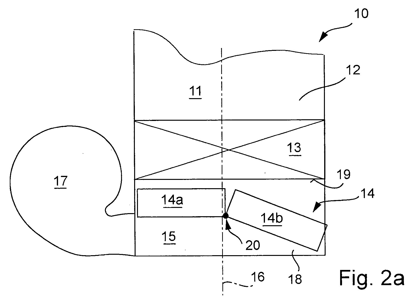
- FIGS 1, 2a, 2b and 3 show different schematic sectional views by an air conditioning system of a vehicle in the area of flow guidance upstream of the distribution box 11 of the two-channel Air conditioning 10.
- each of the flow channel 12 upstream the distributor box 11, the evaporator arranged in the flow channel, and upstream of the evaporator also in the flow channel 12th arranged filters 14 are shown.
- Upstream of the filter 14 is the Anströmkanal 15, through which the fan 17 supplied air across the Extension direction of the flow channel 12 flows.
- the Flow channel 12 and the evaporator mirror symmetry with respect to the Center axis of the flow channel 12 is formed.
- An end wall 18 limited the inflow passage 15 on the opposite side of the filter the incoming air flow and thereby closes off the housing, which the flow channel 12 limited, so that the inflowing air only by the filter can flow along the flow channel.
- Fig. 1 shows the structure of a corresponding region of a two-channel Air conditioning according to the prior art.
- the fan 17 is on one side of the flow channel 12 and leaves the inflowing Air in the inflow passage 15 transversely to the central axis or median plane 16 of the Flow channel 12 a.
- the end wall 18 serves to guide the air flow in the inflow passage 15 so that the flow through the flow channel downstream of the filter 14 over the entire width of the flow channel is formed homogeneously throughout.
- FIG. 2a shows that of FIG. 1 corresponding section of the air conditioning 10 upstream of the distribution box 11, which adjoins the flow channel 12 connects, in which the evaporator 13 and the filter element 14th are arranged.
- the end wall 18 is, like the entire flow channel 12 with respect to the central axis 16 formed mirror-symmetrically.
- the front wall 18 runs in particular parallel to a perpendicular to the Central axis 16 extending plane, as for example by the leading edge 19 of the evaporator 13 is defined. It is, contrary to in the Drawing illustrated embodiment, also possible that the end wall 18 extends from the sides to the central axis 16 so that the distance to the front edge 19 in the region of the central axis 16 is less than in the area the side.
- the blower 17 is arranged, which is the inflowing Air in the inflow passage 15 transversely to the central axis 16 blows.
- the filter element 14 is along a bending axis 20th bent so that the filter element 14 into two segments 14 a and 14 b is divided and arranged the filter element as a whole in the flow channel 12 is that the inflow channel 15 tapers over the filter surface.
- downstream of the filter element 14 is a largely homogeneous distribution of the outflowing air flow through the Flow channel 12 passes through.
- blower can be seen both on the left side of the flow channel 12 are arranged as well as on the right side (Fig. 2b). With an arrangement on the right side only needs the filter element rotated by 180 ° in the flow channel 12 are arranged to achieve a corresponding geometry.
- This mirror-symmetric Training is shown in FIG. 2b, which incidentally the embodiment Fig. 2a corresponds.
- the advantage of this invention Design of the two-channel air conditioning is the fact that independent of whether the vehicle is a right-hand drive or a left-hand drive vehicle is, the same components can be used. Neither blower 17, flow channel 12, the end wall 18 nor filter element 14 must produced and stored in different variants. Only the mounting of the fan and the insertion of the filter element takes place differently.
- Fig. 3 shows an alternative embodiment in which, in difference to the embodiments of Figs. 2a and 2b, the filter element not has only one but two kinks 20, wherein one of the kinks on the inflow side and the other of the kinks downstream of the filter element is formed, so that the filter element 14 in total into three segments 14a, 14b and 14c is divided, each having a different orientation may have within the flow channel 12.
- the tapering of the inflow channel 15th upstream of the filter element 14 for producing a laminar, uniform over the entire width of the flow channel 14 away Air flow is optimized.
- By increasing the number The kinks will make the contour of the filter element more variable, so that an improved flow guidance is made possible. Otherwise, this corresponds the two-channel air conditioning of FIG. 3 of the Fig. 2a and 2b.
Landscapes
- Engineering & Computer Science (AREA)
- Mechanical Engineering (AREA)
- Physics & Mathematics (AREA)
- Thermal Sciences (AREA)
- Air-Conditioning For Vehicles (AREA)
Abstract
Description
- Fig. 1
- einen Bereich einer zweikanaligen Klimaanlage gemäß dem Stand der Technik;
- Fig. 2a
- einen Bereich des Strömungskanals, wobei ein Filterelement mit einer Knickstelle Verwendung findet;
- Fig. 2b
- einen Bereich des Strömungskanals gem. Fig. 2a mit Anströmung und Anordnung des Gebläses auf der anderen Seite der Mittelachse, und
- Fig. 3
- einen entsprechenden Ausschnitt einer schematischen Darstellung einer zweikanaligen Klimaanlage mit einem Filterelement, das zwei Knickstellen aufweist.
Claims (10)
- Zweikanalige Klimaanlage für Fahrzeuge, mit einem Gebläse zum Zuführen eines Luftstromes in einen Strömungskanal, der sich quer zur Abströmrichtung des Gebläses erstreckt und ein Filterelement zum Reinigen der anströmenden Luft beinhaltet,
dadurch gekennzeichnet, dass die Klimaanlage (10) im Bereich des Strömungskanals (12) und seiner Anströmung bezüglich seiner Mittelachse (16) spiegelsymmetrisch ausgebildet ist und das Filterelement (14) derart angeordnet ist, dass sich der über die Filterfläche ergebende Anströmkanal (15) verjüngt. - Zweikanalige Klimaanlage nach Anspruch 1,
dadurch gekennzeichnet, dass das Gebläse (17) wahlweise an einer der beiden Seiten des Strömungskanals (12) angeordnet ist, wobei die andere Seite vorzugsweise durch einen Abschluss verschlossen ist. - Zweikanalige Klimaanlage nach einem der Ansprüche 1 oder 2,
dadurch gekennzeichnet, dass der Strömungskanal (12) stromaufwärts des quer einströmenden Luftstromes durch eine Stirnwand (18) begrenzt wird, wobei die Stirnwand (18) bezüglich der Mittelachse (16) des Strömungskanals (12) symmetrisch ausgebildet ist. - Zweikanalige Klimaanlage nach einem der vorangegangenen Ansprüche,
dadurch gekennzeichnet, dass das Filterelement (14) eine gekrümmte Kontur aufweist und bezüglich der Mittelachse (16) nicht spiegelsymmetrisch ausgerichtet gehalten ist. - Zweikanalige Klimaanlage nach einem der vorangegangenen Ansprüche,
dadurch gekennzeichnet, dass das Filterelement (14) wenigstens eine Knickachse (20) aufweist, an dem es abknickbar ist. - Zweikanalige Klimaanlage nach Anspruch 5,
dadurch gekennzeichnet, dass das Filterelement (14) mehrere Knickachsen (20) aufweist, wobei die Schwenkzentren der Knickachsen (20) jeweils alternierend auf den Seiten des Filterelements (14) ausgebildet sind. - Zweikanalige Klimaanlage nach Anspruch 5 oder 6,
dadurch gekennzeichnet, dass das Filterelement (14) ein Filtermedium aufweist, das zu einem Faltenbalg gefaltet ist, wobei sich die Schwenkachsen in Faltstellen des Faltenbalges befinden. - Filterelement für zweikanalige Klimaanlagen, insbesondere nach einem der vorangegangenen Ansprüche,
dadurch gekennzeichnet, dass das Filterelement (14) aus einem Filtermedium und einem das Filterelement (14) umschließenden Filterrahmen gebildet wird, wobei das Filtermedium und der Filterrahmen Knickstellen zum Abwinkeln aufweist, die wenigstens eine Schwenkachse definieren. - Filterelement nach Anspruch 8,
dadurch gekennzeichnet, dass das Filtermedium zu einem Faltenbalg gefaltet ist, wobei die Schwenkachsen in Faltstellen des Faltenbalgs verlaufen. - Filterelement nach einem der Ansprüche 8 oder 9,
dadurch gekennzeichnet, dass das Filterelement (14) mehrere Knickachsen aufweist, wobei die Schwenkzentren der Knickachsen jeweils alternierend auf den Seiten des Filterelements (14) ausgebildet sind.
Priority Applications (3)
| Application Number | Priority Date | Filing Date | Title |
|---|---|---|---|
| ES03291218T ES2272915T3 (es) | 2003-05-21 | 2003-05-21 | Instalacion de climatizacion de dos canales asi como elemento de filtro para dicha instalacion de climatizacion. |
| DE50305260T DE50305260D1 (de) | 2003-05-21 | 2003-05-21 | Zweikanalige Klimaanlage sowie Filterelement für eine solche Klimaanlage |
| EP03291218A EP1479550B1 (de) | 2003-05-21 | 2003-05-21 | Zweikanalige Klimaanlage sowie Filterelement für eine solche Klimaanlage |
Applications Claiming Priority (1)
| Application Number | Priority Date | Filing Date | Title |
|---|---|---|---|
| EP03291218A EP1479550B1 (de) | 2003-05-21 | 2003-05-21 | Zweikanalige Klimaanlage sowie Filterelement für eine solche Klimaanlage |
Publications (2)
| Publication Number | Publication Date |
|---|---|
| EP1479550A1 true EP1479550A1 (de) | 2004-11-24 |
| EP1479550B1 EP1479550B1 (de) | 2006-10-04 |
Family
ID=33041119
Family Applications (1)
| Application Number | Title | Priority Date | Filing Date |
|---|---|---|---|
| EP03291218A Expired - Lifetime EP1479550B1 (de) | 2003-05-21 | 2003-05-21 | Zweikanalige Klimaanlage sowie Filterelement für eine solche Klimaanlage |
Country Status (3)
| Country | Link |
|---|---|
| EP (1) | EP1479550B1 (de) |
| DE (1) | DE50305260D1 (de) |
| ES (1) | ES2272915T3 (de) |
Cited By (3)
| Publication number | Priority date | Publication date | Assignee | Title |
|---|---|---|---|---|
| FR2938211A1 (fr) * | 2008-11-12 | 2010-05-14 | Valeo Systemes Thermiques | Divergent pour une installation semi-centree de ventilation, de chauffage et/ou de climatisation d'un vehicule automobile. |
| CN115230429A (zh) * | 2022-07-19 | 2022-10-25 | 奇瑞汽车股份有限公司 | 汽车空调进风转接装置及汽车 |
| CN119567806A (zh) * | 2025-01-02 | 2025-03-07 | 岚图汽车科技有限公司 | 空调结构及汽车 |
Citations (4)
| Publication number | Priority date | Publication date | Assignee | Title |
|---|---|---|---|---|
| WO1997000178A1 (fr) * | 1995-06-14 | 1997-01-03 | Valeo Climatisation | Dispositif de chauffage-ventilation et/ou de climatisation de l'habitacle d'un vehicule automobile |
| WO1999012756A1 (de) * | 1997-09-09 | 1999-03-18 | Mannesmann Vdo Ag | Zur anordnung in einem kraftfahrzeug vorgesehener lüftungskasten |
| DE10015256A1 (de) * | 1999-03-30 | 2000-10-05 | Denso Corp | Klimaanlage mit entfernbarem Filter |
| EP1092573A2 (de) * | 1999-10-15 | 2001-04-18 | Calsonic Kansei Corporation | Heizungs- Lüftungs- und/oder Klimaanlagen für Kraftfahrzeuge |
Family Cites Families (1)
| Publication number | Priority date | Publication date | Assignee | Title |
|---|---|---|---|---|
| DE19613345B4 (de) * | 1996-04-03 | 2004-09-30 | Behr Gmbh & Co. Kg | Heizungs- oder Klimaanlage für ein Kraftfahrzeug |
-
2003
- 2003-05-21 DE DE50305260T patent/DE50305260D1/de not_active Expired - Lifetime
- 2003-05-21 ES ES03291218T patent/ES2272915T3/es not_active Expired - Lifetime
- 2003-05-21 EP EP03291218A patent/EP1479550B1/de not_active Expired - Lifetime
Patent Citations (4)
| Publication number | Priority date | Publication date | Assignee | Title |
|---|---|---|---|---|
| WO1997000178A1 (fr) * | 1995-06-14 | 1997-01-03 | Valeo Climatisation | Dispositif de chauffage-ventilation et/ou de climatisation de l'habitacle d'un vehicule automobile |
| WO1999012756A1 (de) * | 1997-09-09 | 1999-03-18 | Mannesmann Vdo Ag | Zur anordnung in einem kraftfahrzeug vorgesehener lüftungskasten |
| DE10015256A1 (de) * | 1999-03-30 | 2000-10-05 | Denso Corp | Klimaanlage mit entfernbarem Filter |
| EP1092573A2 (de) * | 1999-10-15 | 2001-04-18 | Calsonic Kansei Corporation | Heizungs- Lüftungs- und/oder Klimaanlagen für Kraftfahrzeuge |
Cited By (3)
| Publication number | Priority date | Publication date | Assignee | Title |
|---|---|---|---|---|
| FR2938211A1 (fr) * | 2008-11-12 | 2010-05-14 | Valeo Systemes Thermiques | Divergent pour une installation semi-centree de ventilation, de chauffage et/ou de climatisation d'un vehicule automobile. |
| CN115230429A (zh) * | 2022-07-19 | 2022-10-25 | 奇瑞汽车股份有限公司 | 汽车空调进风转接装置及汽车 |
| CN119567806A (zh) * | 2025-01-02 | 2025-03-07 | 岚图汽车科技有限公司 | 空调结构及汽车 |
Also Published As
| Publication number | Publication date |
|---|---|
| EP1479550B1 (de) | 2006-10-04 |
| ES2272915T3 (es) | 2007-05-01 |
| DE50305260D1 (de) | 2006-11-16 |
Similar Documents
| Publication | Publication Date | Title |
|---|---|---|
| EP2508815B1 (de) | Einrichtung zur Beeinflussung einer Luftströmung in einer Komponente einer klimatechnischen Anlage | |
| DE2915501A1 (de) | Lueftungsanlage fuer ein fahrzeug | |
| DE102009057814A1 (de) | Klimaanlage für Fahrzeuge | |
| DE69725667T2 (de) | Fahrzeugheizgerät | |
| DE202009009760U1 (de) | Modular aufgebaute Einheit | |
| DE112019002399B4 (de) | Fluidabgabevorrichtung | |
| DE3046336A1 (de) | Fahrzeug-klimaanlage | |
| DE102006009805A1 (de) | Kabine für Arbeitsfahrzeug | |
| DE69100039T2 (de) | Einbauanordnung zweier luefter einer heiz- und/oder klimaanlage fuer ein kraftfahrzeug. | |
| EP0354163A1 (de) | Vorrichtung zum Beheizen des Fahrgastraumes eines Kraftfahrzeuges | |
| EP1641642B1 (de) | Kraftfahrzeug-klimaanlage | |
| EP1228907A2 (de) | Klimagerät für ein Kraftfahrzeug | |
| EP1312493B1 (de) | Luftmischeinrichtung für eine Heizungs- oder Klimaanlage | |
| EP1479550B1 (de) | Zweikanalige Klimaanlage sowie Filterelement für eine solche Klimaanlage | |
| DE10147112A1 (de) | Steuerklappe, z.B. für eine Vorrichtung zum Temperieren und Belüften von Kraftfahrzeugen | |
| DE102010039674A1 (de) | Vorrichtung zur Mischung zweier Luftströme | |
| DE112016005216T5 (de) | Luftblasgerät | |
| EP2996923B1 (de) | Luftauslass | |
| DE10320645A1 (de) | Klappe für Luftkanäle und Strömungsleiteinrichtung | |
| DE10147113A1 (de) | Vorrichtung zum Temperieren und Belüften von Kraftfahrzeugen | |
| EP1613492B1 (de) | Vorrichtung zum austausch von wärme | |
| EP1308325B1 (de) | Luftstromschalteinrichtung | |
| DE102014105035B4 (de) | Kraftfahrzeug-Klimaanlage mit mehreren Steuerklappen | |
| DE102019205684A1 (de) | Lüfter | |
| DE2156239B2 (de) | Konvektor mit einer Anzahl von parallelen, im wesentlichen ebenen Blechflanschen |
Legal Events
| Date | Code | Title | Description |
|---|---|---|---|
| PUAI | Public reference made under article 153(3) epc to a published international application that has entered the european phase |
Free format text: ORIGINAL CODE: 0009012 |
|
| AK | Designated contracting states |
Kind code of ref document: A1 Designated state(s): AT BE BG CH CY CZ DE DK EE ES FI FR GB GR HU IE IT LI LU MC NL PT RO SE SI SK TR |
|
| AX | Request for extension of the european patent |
Extension state: AL LT LV MK |
|
| 17P | Request for examination filed |
Effective date: 20050524 |
|
| AKX | Designation fees paid |
Designated state(s): CZ DE ES FR GB IT |
|
| RAP1 | Party data changed (applicant data changed or rights of an application transferred) |
Owner name: BEHR FRANCE ROUFFACH SAS |
|
| GRAP | Despatch of communication of intention to grant a patent |
Free format text: ORIGINAL CODE: EPIDOSNIGR1 |
|
| GRAS | Grant fee paid |
Free format text: ORIGINAL CODE: EPIDOSNIGR3 |
|
| GRAA | (expected) grant |
Free format text: ORIGINAL CODE: 0009210 |
|
| AK | Designated contracting states |
Kind code of ref document: B1 Designated state(s): CZ DE ES FR GB IT |
|
| PG25 | Lapsed in a contracting state [announced via postgrant information from national office to epo] |
Ref country code: IT Free format text: LAPSE BECAUSE OF FAILURE TO SUBMIT A TRANSLATION OF THE DESCRIPTION OR TO PAY THE FEE WITHIN THE PRESCRIBED TIME-LIMIT;WARNING: LAPSES OF ITALIAN PATENTS WITH EFFECTIVE DATE BEFORE 2007 MAY HAVE OCCURRED AT ANY TIME BEFORE 2007. THE CORRECT EFFECTIVE DATE MAY BE DIFFERENT FROM THE ONE RECORDED. Effective date: 20061004 |
|
| REG | Reference to a national code |
Ref country code: GB Ref legal event code: FG4D Free format text: NOT ENGLISH |
|
| REF | Corresponds to: |
Ref document number: 50305260 Country of ref document: DE Date of ref document: 20061116 Kind code of ref document: P |
|
| GBT | Gb: translation of ep patent filed (gb section 77(6)(a)/1977) |
Effective date: 20061214 |
|
| ET | Fr: translation filed | ||
| REG | Reference to a national code |
Ref country code: ES Ref legal event code: FG2A Ref document number: 2272915 Country of ref document: ES Kind code of ref document: T3 |
|
| PLBE | No opposition filed within time limit |
Free format text: ORIGINAL CODE: 0009261 |
|
| STAA | Information on the status of an ep patent application or granted ep patent |
Free format text: STATUS: NO OPPOSITION FILED WITHIN TIME LIMIT |
|
| 26N | No opposition filed |
Effective date: 20070705 |
|
| PGFP | Annual fee paid to national office [announced via postgrant information from national office to epo] |
Ref country code: CZ Payment date: 20080516 Year of fee payment: 6 |
|
| PGFP | Annual fee paid to national office [announced via postgrant information from national office to epo] |
Ref country code: IT Payment date: 20080520 Year of fee payment: 6 |
|
| PGFP | Annual fee paid to national office [announced via postgrant information from national office to epo] |
Ref country code: GB Payment date: 20080520 Year of fee payment: 6 |
|
| PGFP | Annual fee paid to national office [announced via postgrant information from national office to epo] |
Ref country code: ES Payment date: 20090526 Year of fee payment: 7 |
|
| GBPC | Gb: european patent ceased through non-payment of renewal fee |
Effective date: 20090521 |
|
| PG25 | Lapsed in a contracting state [announced via postgrant information from national office to epo] |
Ref country code: CZ Free format text: LAPSE BECAUSE OF NON-PAYMENT OF DUE FEES Effective date: 20090521 |
|
| PG25 | Lapsed in a contracting state [announced via postgrant information from national office to epo] |
Ref country code: GB Free format text: LAPSE BECAUSE OF NON-PAYMENT OF DUE FEES Effective date: 20090521 |
|
| PG25 | Lapsed in a contracting state [announced via postgrant information from national office to epo] |
Ref country code: IT Free format text: LAPSE BECAUSE OF NON-PAYMENT OF DUE FEES Effective date: 20090521 |
|
| REG | Reference to a national code |
Ref country code: ES Ref legal event code: FD2A Effective date: 20110712 |
|
| PG25 | Lapsed in a contracting state [announced via postgrant information from national office to epo] |
Ref country code: ES Free format text: LAPSE BECAUSE OF NON-PAYMENT OF DUE FEES Effective date: 20110630 |
|
| PG25 | Lapsed in a contracting state [announced via postgrant information from national office to epo] |
Ref country code: ES Free format text: LAPSE BECAUSE OF NON-PAYMENT OF DUE FEES Effective date: 20100522 |
|
| PGFP | Annual fee paid to national office [announced via postgrant information from national office to epo] |
Ref country code: DE Payment date: 20120625 Year of fee payment: 10 |
|
| PGFP | Annual fee paid to national office [announced via postgrant information from national office to epo] |
Ref country code: FR Payment date: 20120614 Year of fee payment: 10 |
|
| PG25 | Lapsed in a contracting state [announced via postgrant information from national office to epo] |
Ref country code: DE Free format text: LAPSE BECAUSE OF NON-PAYMENT OF DUE FEES Effective date: 20131203 |
|
| REG | Reference to a national code |
Ref country code: DE Ref legal event code: R119 Ref document number: 50305260 Country of ref document: DE Effective date: 20131203 |
|
| REG | Reference to a national code |
Ref country code: FR Ref legal event code: ST Effective date: 20140131 |
|
| PG25 | Lapsed in a contracting state [announced via postgrant information from national office to epo] |
Ref country code: FR Free format text: LAPSE BECAUSE OF NON-PAYMENT OF DUE FEES Effective date: 20130531 |