EP1479490A2 - Vorrichtung zur Winkeleinstellung für Maschinen zum Bearbeiten von Platten aus Holz oder dergleichen - Google Patents
Vorrichtung zur Winkeleinstellung für Maschinen zum Bearbeiten von Platten aus Holz oder dergleichen Download PDFInfo
- Publication number
- EP1479490A2 EP1479490A2 EP04425362A EP04425362A EP1479490A2 EP 1479490 A2 EP1479490 A2 EP 1479490A2 EP 04425362 A EP04425362 A EP 04425362A EP 04425362 A EP04425362 A EP 04425362A EP 1479490 A2 EP1479490 A2 EP 1479490A2
- Authority
- EP
- European Patent Office
- Prior art keywords
- fence
- panel
- allow
- feed
- reached
- Prior art date
- Legal status (The legal status is an assumption and is not a legal conclusion. Google has not performed a legal analysis and makes no representation as to the accuracy of the status listed.)
- Withdrawn
Links
Images


Classifications
-
- B—PERFORMING OPERATIONS; TRANSPORTING
- B27—WORKING OR PRESERVING WOOD OR SIMILAR MATERIAL; NAILING OR STAPLING MACHINES IN GENERAL
- B27G—ACCESSORY MACHINES OR APPARATUS FOR WORKING WOOD OR SIMILAR MATERIALS; TOOLS FOR WORKING WOOD OR SIMILAR MATERIALS; SAFETY DEVICES FOR WOOD WORKING MACHINES OR TOOLS
- B27G5/00—Machines or devices for working mitre joints with even abutting ends
- B27G5/02—Machines or devices for working mitre joints with even abutting ends for sawing mitre joints; Mitre boxes
- B27G5/023—Machines or devices for working mitre joints with even abutting ends for sawing mitre joints; Mitre boxes the mitre angle being adjusted by positioning a workpiece relative to a fixed saw
-
- B—PERFORMING OPERATIONS; TRANSPORTING
- B23—MACHINE TOOLS; METAL-WORKING NOT OTHERWISE PROVIDED FOR
- B23D—PLANING; SLOTTING; SHEARING; BROACHING; SAWING; FILING; SCRAPING; LIKE OPERATIONS FOR WORKING METAL BY REMOVING MATERIAL, NOT OTHERWISE PROVIDED FOR
- B23D47/00—Sawing machines or sawing devices working with circular saw blades, characterised only by constructional features of particular parts
- B23D47/02—Sawing machines or sawing devices working with circular saw blades, characterised only by constructional features of particular parts of frames; of guiding arrangements for work-table or saw-carrier
- B23D47/025—Sawing machines or sawing devices working with circular saw blades, characterised only by constructional features of particular parts of frames; of guiding arrangements for work-table or saw-carrier of tables
-
- B—PERFORMING OPERATIONS; TRANSPORTING
- B23—MACHINE TOOLS; METAL-WORKING NOT OTHERWISE PROVIDED FOR
- B23D—PLANING; SLOTTING; SHEARING; BROACHING; SAWING; FILING; SCRAPING; LIKE OPERATIONS FOR WORKING METAL BY REMOVING MATERIAL, NOT OTHERWISE PROVIDED FOR
- B23D59/00—Accessories specially designed for sawing machines or sawing devices
- B23D59/001—Measuring or control devices, e.g. for automatic control of work feed pressure on band saw blade
-
- B—PERFORMING OPERATIONS; TRANSPORTING
- B27—WORKING OR PRESERVING WOOD OR SIMILAR MATERIAL; NAILING OR STAPLING MACHINES IN GENERAL
- B27B—SAWS FOR WOOD OR SIMILAR MATERIAL; COMPONENTS OR ACCESSORIES THEREFOR
- B27B27/00—Guide fences or stops for timber in saw mills or sawing machines; Measuring equipment thereon
- B27B27/08—Guide fences or stops for timber in saw mills or sawing machines; Measuring equipment thereon arranged adjustably, not limited to only one of the groups B27B27/02 - B27B27/06
-
- B—PERFORMING OPERATIONS; TRANSPORTING
- B27—WORKING OR PRESERVING WOOD OR SIMILAR MATERIAL; NAILING OR STAPLING MACHINES IN GENERAL
- B27B—SAWS FOR WOOD OR SIMILAR MATERIAL; COMPONENTS OR ACCESSORIES THEREFOR
- B27B27/00—Guide fences or stops for timber in saw mills or sawing machines; Measuring equipment thereon
- B27B27/10—Devices for moving or adjusting the guide fences or stops
-
- B—PERFORMING OPERATIONS; TRANSPORTING
- B27—WORKING OR PRESERVING WOOD OR SIMILAR MATERIAL; NAILING OR STAPLING MACHINES IN GENERAL
- B27B—SAWS FOR WOOD OR SIMILAR MATERIAL; COMPONENTS OR ACCESSORIES THEREFOR
- B27B5/00—Sawing machines working with circular or cylindrical saw blades; Components or equipment therefor
- B27B5/16—Saw benches
- B27B5/22—Saw benches with non-feedable circular saw blade
- B27B5/222—Saw benches with non-feedable circular saw blade the saw blade being arranged underneath the work-table; Guiding arrangements for the work-table
Definitions
- the present invention relates to an angular positioning device for machines for machining panels made of wood or similar materials.
- the machines in question are for machining panels made of wood or similar materials, and more specifically a machine for sawing panels, but it may also advantageously be used to machine other materials such as fibre materials, panes of glass or synthetic materials, etc.
- the current machines for cutting wooden panels substantially consist of a support base with an upper portion forming a horizontal table divided into a fixed portion from which the cutting tool projects and a mobile portion, or carriage, mainly extending in a direction in which the panel to be cut slides.
- the table - fixed portion has a slit, aligned with the direction of sliding, from which the portion of circular saw with a (nominally) horizontal axis projects.
- the accessories are normally mounted on the machine according to the type of machining and the dimensions of the panels to be machined: for example, for very large panels an auxiliary carriage which can be connected to the mobile part of the table is used to support the panel and extends in a cantilever fashion transversally from one side of the table; for medium - small sized panels (the most common) a stop fence is used which pivots, at one end, at the mobile worktable in a position close to the circular saw blade then extends in a cantilever fashion outside the worktable.
- the stop fence normally has a graduated rod, slidably positioned above the fence, to display the size of the panel and has a stop surface for the edge of the panel to be cut, defining the final panel size.
- the operator positions the panel against the fence, adjusts the panel according to the measurement to be made using the graduated reference rod, then feeds the panel - table assembly towards the blade to make the cut.
- the fence has the graduated rod with the zero point at the (outer) face of the blade facing the fence, since the latter will form the visible panel cutting surface. Therefore, thanks to the graduated rod - adjustable stop assembly, the machine operator can position the panel to be cut in the precise position in order to obtain the predetermined measurement displayed. This is the case under standard conditions, that is to say, with the fence at a right angle to the cutting surface.
- These circular saw machines are also usually used to make slanting or angled cuts, relative to the position at a right angle to the above-mentioned direction of feed.
- the fence must be angled, one way or the other, relative to the circular saw, by moving it about the fence pivot point and locking it at the angle reached with the aid, on the worktable, of a reference table (auxiliary and positioned below the fence) having a curved configuration (known as a steady rest to experts in the field) for displaying the angle of inclination to be reached.
- a reference table auxiliary and positioned below the fence
- the measurement of the cut, or rather, the position of the stop on the fence must therefore be calculated by the operator at least according to the angle of panel deviation: through the software related to the machine or approximation data.
- the aim of the present invention is, therefore, to overcome these disadvantages by providing an angular positioning device for machines for machining panels which is extremely practical, with rapid fence positioning and a high level of precision in automatically sizing the panel to be machined, i.e.: without the need for calculation processing; all with a structure and dimensions compatible with the current machine architectures.
- an angular positioning device applicable on machines for machining panels, comprising: a worktable consisting of a fixed supporting portion and a portion which is mobile, in both directions, along a direction of feed; a machining tool attached to the fixed portion and positioned parallel with the direction of feed; a reference and rule fence for the panel, which pivots on the mobile portion and whose angle can be adjusted relative to the direction of feed to define angled cuts on the panel;
- the fence has panel reference - stop parts designed to allow the display of an operating reference dimension on the fence and having a cutting zero point belonging to the tool cutting plane;
- the device comprises means for adjusting the linear position of the fence relative to the cutting plane, said means operating between the fence and the pivot point, designed to allow the fence to be adjusted parallel with itself, according to the angular position reached, so as to keep the measurement defined between the reference - stop parts and the zero point constant at any angle value.
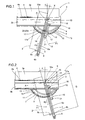
- the angular positioning device disclosed is particularly applicable on machines, labelled 1 as a whole, for machining panels 2 made of wood or similar materials, such as fibre materials, panes of glass or synthetic materials, etc.
- These machines 1 for machining panels 2 basically comprise:
- the fence 5 also has panel 2 reference and stop parts 6, designed to allow the display of a reference dimension Q on the fence 5.
- the parts 6 may comprise, by way of example and without limiting the scope of the invention, a magnetic plate 6a positioned on the fence 5 and connected to a first display 6b for the reference dimension Q and a stop surface 6c connected to the display 6b and able to slide along the fence 5.
- the dimension Q is calculated with the fence 5 cutting zero point PZ belonging to the tool 4 cutting plane 4a (see Figure 5).
- the numeral 7 denotes means for displaying the angle ⁇ reached by the fence 5, positioned on the mobile portion 3b and at the fence 5.
- these display means 7 may comprise a semicircular plate 7a, attached or attachable (according to operating requirements) to the mobile portion 3b and positioned below the fence 5.
- the numeral 8 denotes means for adjusting the linear position of the fence 5 relative to the tool 4 cutting plane 4a, operating between the fence 5 and its pivot point X on the mobile portion 3b.
- These adjusting means 8 allow the fence 5 to be adjusted parallel with itself, according to the angular position it has reached and in such a way as to maintain the measurement or dimension Q defined between the reference - stop parts 7 and the zero point PZ constant at any angle value ⁇ .
- the adjusting means 8 comprise cam means 9 positioned on the display means 7 and interacting with the fence 5. They also comprise the fence 5 which is divided into two separate parts, the first consisting of the part of the fence 5 in contact with the panel 2 and a connecting bar 10, one end of which is attached to the mobile table 3b, forming the pivot point X, by means of a connecting element 10a (for example a pin).
- a connecting element 10a for example a pin
- the connecting bar 10 is slidably connected to the fence 5 in such a way that it allows the fence 5 to move longitudinally in both directions (see arrows F2), according to the above-mentioned angular position adopted relative to the direction of feed A.
- the cam means 9 comprise a first, curved groove 11 made in the semicircular plate 7a and in which a first, cam follower pin 12 can engage, the pin projecting from the bottom of the fence 5 and designed to allow the fence 5 to slide in a linear fashion, along the connecting bar 10 between at least two positions closest to the pivot point X, corresponding to fence 5 maximum inclination end positions, in both directions (examples are partially visible in Figures 1 and 2), relative to the direction of feed A.
- the furthest pivot point X - fence 5 position may be, for example, with the fence 5 at a right angle to the direction of feed A.
- the first groove 11 has numeric references designed to display the angle ⁇ reached by the fence 5.
- first groove 11 there is a second, guide pin 14 projecting from the fence 5, which may engage in corresponding seats 15 made in the bottom of the first groove 11 and forming reference angles which can be reached by the fence 5.
- This second pin 14 is coaxial with the first, cam follower pin 12 and is controlled by a push-button 14b by means of a relative connecting rod 14a.
- This push-button 14b allows the stable connection between the second pin 14a and the seats 15 to be released during fence 5 movement.
- locking means 16 which operate on the fence 5 when it reaches a predetermined angular position ⁇ .
- These locking means 16 comprise a plate 17 attached to the side of the fence 5 and having a third, reversible locking pin 18 which engages in a channel 19 in the mobile portion 3b.
- This plate 17 has a sliding slot 17a, extending parallel with the fence 5, and in which the third pin 18 engages in such a way as to allow fence 5 angular movement irrespective of the position of the third pin 18, which can slide inside the channel 19.
- the semicircular plate 7a has a second, curved groove 13.
- a magnetic plate 20 is attached, which detects the angular position ⁇ reached and interacts with a magnetic sensor 20a, which slides inside the second groove 13.
- the sensor 20a is attached to the plate 17 and connected to numeric display means 21 for the angular position reached by the fence 5. These means may consist of a second display 21 positioned on the side locking plate 17, so that the precise angular position reached can be checked.
- the device structured in this way completely fulfils the preset aims thanks to an extremely simple and effective structure which allows automatic adjustment, thanks to division of the fence into two parts and the cam profile - pin interaction, of the fence linear position according to the angle reached.
- the system is precise, automatic and does not require calculations or further adaptation of the fence by the operator, who need only position the fence: this also significantly speeds up machine tooling operations, with drastically lower costs.
Landscapes
- Life Sciences & Earth Sciences (AREA)
- Engineering & Computer Science (AREA)
- Mechanical Engineering (AREA)
- Wood Science & Technology (AREA)
- Forests & Forestry (AREA)
- Details Of Cutting Devices (AREA)
- Re-Forming, After-Treatment, Cutting And Transporting Of Glass Products (AREA)
Applications Claiming Priority (2)
| Application Number | Priority Date | Filing Date | Title |
|---|---|---|---|
| ITBO20030324 ITBO20030324A1 (it) | 2003-05-23 | 2003-05-23 | Dispositivo di posizionamento angolare per macchine per la |
| ITBO20030324 | 2003-05-23 |
Publications (2)
| Publication Number | Publication Date |
|---|---|
| EP1479490A2 true EP1479490A2 (de) | 2004-11-24 |
| EP1479490A3 EP1479490A3 (de) | 2005-01-12 |
Family
ID=33042680
Family Applications (1)
| Application Number | Title | Priority Date | Filing Date |
|---|---|---|---|
| EP04425362A Withdrawn EP1479490A3 (de) | 2003-05-23 | 2004-05-19 | Vorrichtung zur Winkeleinstellung für Maschinen zum Bearbeiten von Platten aus Holz oder dergleichen |
Country Status (2)
| Country | Link |
|---|---|
| EP (1) | EP1479490A3 (de) |
| IT (1) | ITBO20030324A1 (de) |
Cited By (10)
| Publication number | Priority date | Publication date | Assignee | Title |
|---|---|---|---|---|
| EP1800815A1 (de) * | 2005-12-23 | 2007-06-27 | Otto Martin Maschinenbau GmbH & Co. KG | Holzbearbeitungsmaschine und Verfahren zur Ermittlung eines Korrekturmasses bei Holzbearbeitungsmaschinen |
| US7530173B2 (en) * | 2005-08-29 | 2009-05-12 | Economaki John J | Variable cutting angle hand plane |
| EP2106889A2 (de) | 2008-03-31 | 2009-10-07 | Otto Martin Maschinenbau GmbH & Co. KG | Verschiebbares Anschlaglineal |
| ES2342650A1 (es) * | 2009-01-08 | 2010-07-09 | Cañas Y Gomez S.L. | Escuadra articulada. |
| CN102490222A (zh) * | 2011-12-08 | 2012-06-13 | 无锡凤凰画材有限公司 | 木料榫头自动加工机的回转夹紧块履带 |
| CN102490221A (zh) * | 2011-12-08 | 2012-06-13 | 无锡凤凰画材有限公司 | 木料榫头自动加工机 |
| DE102015205444B4 (de) * | 2014-03-25 | 2016-12-01 | Scm Group S.P.A. | Positionierungssystem von zu bearbeitenden Werkstücken und mit solchem System ausgestattete Maschine |
| CN107116614A (zh) * | 2016-05-16 | 2017-09-01 | 陈华祥 | 一种定角度木板切割机 |
| DE102019004497A1 (de) * | 2019-06-26 | 2020-12-31 | Frank Hüglin | Digitaler Winkelanschlag 180 Präzision, DWA180P |
| CN118808736A (zh) * | 2024-09-03 | 2024-10-22 | 中山市特顺电器有限公司 | 一种搅拌机制造用切割装置 |
Family Cites Families (5)
| Publication number | Priority date | Publication date | Assignee | Title |
|---|---|---|---|---|
| DE9103189U1 (de) * | 1991-03-15 | 1991-06-13 | Ant. Panhans GmbH Werkzeug- und Maschinenfabrik, 7480 Sigmaringen | Gehrungs- und Sägeanschlag, insbesondere für eine Holzsägemaschine |
| DE9207811U1 (de) * | 1992-06-10 | 1993-01-14 | Georg Ott Werkzeug- und Maschinenfabrik GmbH & Co, 7900 Ulm | Gehrungsanschlag |
| DE9303843U1 (de) * | 1993-03-16 | 1993-07-29 | Wilhelm Altendorf GmbH & Co KG, 32429 Minden | Winkelanschlag für Werkzeugmaschinen |
| DE4312767A1 (de) * | 1993-04-20 | 1994-10-27 | Reich Spezialmaschinen Gmbh | Gehrungsanschlag |
| EP0692349A3 (de) * | 1994-06-21 | 1997-01-15 | Optical And Electronic Enginee | Positioniervorrichtung, insbesondere für Sägen und Fräsmaschinen |
-
2003
- 2003-05-23 IT ITBO20030324 patent/ITBO20030324A1/it unknown
-
2004
- 2004-05-19 EP EP04425362A patent/EP1479490A3/de not_active Withdrawn
Cited By (13)
| Publication number | Priority date | Publication date | Assignee | Title |
|---|---|---|---|---|
| US7530173B2 (en) * | 2005-08-29 | 2009-05-12 | Economaki John J | Variable cutting angle hand plane |
| EP1800815A1 (de) * | 2005-12-23 | 2007-06-27 | Otto Martin Maschinenbau GmbH & Co. KG | Holzbearbeitungsmaschine und Verfahren zur Ermittlung eines Korrekturmasses bei Holzbearbeitungsmaschinen |
| EP2106889A3 (de) * | 2008-03-31 | 2012-04-25 | Otto Martin Maschinenbau GmbH & Co. KG | Verschiebbares Anschlaglineal |
| EP2106889A2 (de) | 2008-03-31 | 2009-10-07 | Otto Martin Maschinenbau GmbH & Co. KG | Verschiebbares Anschlaglineal |
| ES2342650A1 (es) * | 2009-01-08 | 2010-07-09 | Cañas Y Gomez S.L. | Escuadra articulada. |
| ES2342650B1 (es) * | 2009-01-08 | 2011-06-09 | Cañas Y Gomez S.L. | Escuadra articulada. |
| WO2010079248A1 (es) * | 2009-01-08 | 2010-07-15 | Cañas Y Gomez, S.L. | Escuadra articulada |
| CN102490222A (zh) * | 2011-12-08 | 2012-06-13 | 无锡凤凰画材有限公司 | 木料榫头自动加工机的回转夹紧块履带 |
| CN102490221A (zh) * | 2011-12-08 | 2012-06-13 | 无锡凤凰画材有限公司 | 木料榫头自动加工机 |
| DE102015205444B4 (de) * | 2014-03-25 | 2016-12-01 | Scm Group S.P.A. | Positionierungssystem von zu bearbeitenden Werkstücken und mit solchem System ausgestattete Maschine |
| CN107116614A (zh) * | 2016-05-16 | 2017-09-01 | 陈华祥 | 一种定角度木板切割机 |
| DE102019004497A1 (de) * | 2019-06-26 | 2020-12-31 | Frank Hüglin | Digitaler Winkelanschlag 180 Präzision, DWA180P |
| CN118808736A (zh) * | 2024-09-03 | 2024-10-22 | 中山市特顺电器有限公司 | 一种搅拌机制造用切割装置 |
Also Published As
| Publication number | Publication date |
|---|---|
| EP1479490A3 (de) | 2005-01-12 |
| ITBO20030324A1 (it) | 2004-11-24 |
Similar Documents
| Publication | Publication Date | Title |
|---|---|---|
| US4995288A (en) | Saw guide | |
| US4078309A (en) | Miter saw | |
| US4600184A (en) | Tool fence | |
| US4290464A (en) | Holder for portable electric cutting instrument | |
| US7614330B2 (en) | Rip fence for a table saw | |
| US20120186410A1 (en) | Multi-Function Power Saw | |
| US20030066573A1 (en) | Radial overarm router | |
| EP2347876A1 (de) | Tischsäge | |
| US3727502A (en) | Saw-table construction | |
| EP3191271B1 (de) | Gehrungsmassstabarretierung für eine formatkreissäge | |
| US20210129372A1 (en) | Moveable Saw Fence and Saw Support | |
| EP2969340B1 (de) | Gehrungstischsäge | |
| EP1837142A1 (de) | Gehrungssäge | |
| KR102211833B1 (ko) | 판재절단 작업대의 각도조절장치 | |
| US6073532A (en) | Cove molding setup device and method | |
| KR200352626Y1 (ko) | 면취기 | |
| EP2969331B1 (de) | Kraftwerkzeug in form eines integrierten schneidesystems | |
| EP1205285B1 (de) | Plattensäge | |
| KR101944995B1 (ko) | 둥근톱기계장치 | |
| EP1479489B1 (de) | Maschine zum Bearbeiten von Platten | |
| EP1787774B1 (de) | Gehrungslehre | |
| EP1479471B1 (de) | Maschine zum Bearbeiten von Platten | |
| EP1479490A3 (de) | Vorrichtung zur Winkeleinstellung für Maschinen zum Bearbeiten von Platten aus Holz oder dergleichen | |
| US11020872B2 (en) | Miter saw | |
| KR101970945B1 (ko) | 절단각 각도범위를 확장한 디지털 슬라이딩 커터 |
Legal Events
| Date | Code | Title | Description |
|---|---|---|---|
| PUAI | Public reference made under article 153(3) epc to a published international application that has entered the european phase |
Free format text: ORIGINAL CODE: 0009012 |
|
| AK | Designated contracting states |
Kind code of ref document: A2 Designated state(s): AT BE BG CH CY CZ DE DK EE ES FI FR GB GR HU IE IT LI LU MC NL PL PT RO SE SI SK TR |
|
| AX | Request for extension of the european patent |
Extension state: AL HR LT LV MK |
|
| PUAL | Search report despatched |
Free format text: ORIGINAL CODE: 0009013 |
|
| AK | Designated contracting states |
Kind code of ref document: A3 Designated state(s): AT BE BG CH CY CZ DE DK EE ES FI FR GB GR HU IE IT LI LU MC NL PL PT RO SE SI SK TR |
|
| AX | Request for extension of the european patent |
Extension state: AL HR LT LV MK |
|
| 17P | Request for examination filed |
Effective date: 20050511 |
|
| AKX | Designation fees paid |
Designated state(s): AT BE BG CH CY CZ DE DK EE ES FI FR GB GR HU IE IT LI LU MC NL PL PT RO SE SI SK TR |
|
| STAA | Information on the status of an ep patent application or granted ep patent |
Free format text: STATUS: THE APPLICATION IS DEEMED TO BE WITHDRAWN |
|
| 18D | Application deemed to be withdrawn |
Effective date: 20060119 |