EP1479464A2 - Vertical injection molding machine using three chambers - Google Patents
Vertical injection molding machine using three chambers Download PDFInfo
- Publication number
- EP1479464A2 EP1479464A2 EP04090146A EP04090146A EP1479464A2 EP 1479464 A2 EP1479464 A2 EP 1479464A2 EP 04090146 A EP04090146 A EP 04090146A EP 04090146 A EP04090146 A EP 04090146A EP 1479464 A2 EP1479464 A2 EP 1479464A2
- Authority
- EP
- European Patent Office
- Prior art keywords
- chamber
- rod
- metal
- conduit
- injection
- Prior art date
- Legal status (The legal status is an assumption and is not a legal conclusion. Google has not performed a legal analysis and makes no representation as to the accuracy of the status listed.)
- Withdrawn
Links
Images


Classifications
-
- H—ELECTRICITY
- H10—SEMICONDUCTOR DEVICES; ELECTRIC SOLID-STATE DEVICES NOT OTHERWISE PROVIDED FOR
- H10W—GENERIC PACKAGES, INTERCONNECTIONS, CONNECTORS OR OTHER CONSTRUCTIONAL DETAILS OF DEVICES COVERED BY CLASS H10
- H10W74/00—Encapsulations, e.g. protective coatings
- H10W74/01—Manufacture or treatment
-
- B—PERFORMING OPERATIONS; TRANSPORTING
- B22—CASTING; POWDER METALLURGY
- B22D—CASTING OF METALS; CASTING OF OTHER SUBSTANCES BY THE SAME PROCESSES OR DEVICES
- B22D17/00—Pressure die casting or injection die casting, i.e. casting in which the metal is forced into a mould under high pressure
- B22D17/20—Accessories: Details
- B22D17/30—Accessories for supplying molten metal, e.g. in rations
-
- B—PERFORMING OPERATIONS; TRANSPORTING
- B22—CASTING; POWDER METALLURGY
- B22D—CASTING OF METALS; CASTING OF OTHER SUBSTANCES BY THE SAME PROCESSES OR DEVICES
- B22D17/00—Pressure die casting or injection die casting, i.e. casting in which the metal is forced into a mould under high pressure
- B22D17/08—Cold chamber machines, i.e. with unheated press chamber into which molten metal is ladled
- B22D17/12—Cold chamber machines, i.e. with unheated press chamber into which molten metal is ladled with vertical press motion
-
- H—ELECTRICITY
- H05—ELECTRIC TECHNIQUES NOT OTHERWISE PROVIDED FOR
- H05K—PRINTED CIRCUITS; CASINGS OR CONSTRUCTIONAL DETAILS OF ELECTRIC APPARATUS; MANUFACTURE OF ASSEMBLAGES OF ELECTRICAL COMPONENTS
- H05K13/00—Apparatus or processes specially adapted for manufacturing or adjusting assemblages of electric components
- H05K13/04—Mounting of components, e.g. of leadless components
- H05K13/046—Surface mounting
- H05K13/0469—Surface mounting by applying a glue or viscous material
Definitions
- the invention relates to a method and apparatus for manufacturing metallic parts, more particularly to a method and apparatus for manufacturing metallic parts by a process involving injection of liquid metal into a mold, including die casting methods.
- molten metal is poured into a sleeve which is secured on a die plate and connected to an inlet opening to the mold cavity. Molten metal is injected by a plunger into the die. The molten metal in the sleeve is easily cooled down when it spreads at the bottom of the sleeve as the plunger moves forward slowly to discharge air or gas. Cooled molten metal in the sleeve forms a chilled fraction and semi-solid or solid particles. The chilled fraction and particles are injected into the molding die causing the physical properties of molded parts to be deteriorated.
- Cooled molten metal increases the viscosity of the molten metal and makes it difficult to fill the mold cavity. Further, it causes blemishes on surface of a molded part. This is a serious problem particularly for magnesium alloys for which the latent heat of solidification is small (smaller than aluminum, lead and zinc). Because of the small latent heat of solidification, magnesium solidifies quickly when it comes in contact with materials having a lower temperature.
- Hot sleeves have been used, but the heated sleeve is not as hot as liquidus temperature of the metal because the sleeve is connected to a molding die whose temperature has to be below the solidus temperature of the metal.
- the molding die temperature must be sufficiently below the solidus temperature of the molten metal to produce an adequate solidification rate. That is, a solidification rate which reflects the required time for an operation cycle.
- Molten metal poured into the sleeve has a substantially higher temperature than the liquidus temperature of the metal to counter the cooling in the sleeve. This is a disadvantage in energy cost for heating.
- the cold chamber apparatus forms a thick round plate as a part of the casting, often called a biscuit, in the sleeve between a plunger head and an inlet of a die. After the casting is pulled away from the molding dies when the dies are opened, the biscuit is cut away from the casting and recycled. However, sometimes the biscuit is larger than the product. This is a disadvantageous use of metal which has a substantial recycling cost.
- an injection mechanism is submerged in molten metal in a furnace.
- the temperature of the molten metal to be injected is maintained above its liquidus.
- the injection mechanism has a shot cylinder with a plunger, gooseneck chamber and a nozzle at the end of thereof.
- the molten metal is injected through a gooseneck-type passage and through a nozzle into the die cavity without forming a biscuit. This is an advantage of hot chamber die casting apparatus.
- a hot chamber apparatus over a cold chamber apparatus is the time for an operation cycle.
- the casting is formed by injecting molten metal into a mold cavity between closed dies and cooling to until the casting is solid.
- the dies are separated and the molded part is pulled away, lubricant is sprayed onto the opened dies, and the dies are closed again. Then, the dies are ready to start the next operation cycle.
- the molten metal is poured into the injection sleeve when the molding dies are closed, i.e., when the dies are ready to start the next operation cycle, so that the molten metal does not spill out from the inlet opening of the die because the injection sleeve directly communicates with a die.
- hot chamber die casting apparatus fill molten metal in the gooseneck and a shot cylinder system by returning an injection plunger to its fill up position.
- Molten metal is supplied through an opening or fill port on a shot cylinder.
- the nozzle is positioned by inclining the gooseneck chamber.
- the molten metal in the nozzle gooseneck system tends to flow back into the furnace through the fill port on the shot sleeve, reaching a hydrostatic level when the dies are opened.
- U.S. patents 3,123,875, 3,172,174, 3,270,378, 3,474,875 and 3,491,827 propose creating a vacuum in the gooseneck by return or reverse stroke of the plunger to draw back molten metal from the nozzle and extreme tip of the sprue: These patents disclose mechanisms attached to the shot cylinder and a plunger system so that the created vacuum is kept intact until after the dies have been separated and the solidified casting has been withdrawn from the sprue opening of the stationary die.
- Die casting apparatus are also classified according to the arrangement of the injection system, that is, horizontal and vertical.
- an injection system is horizontally arranged for horizontally injecting molten metal into molding dies.
- a vertical die casting apparatus has a vertically arranged injection system for vertical injection of molten metal.
- One embodiment of the present invention includes a vertical injection machine comprising a first chamber for supplying liquid metal, a second chamber located lower than the first chamber, a first conduit connecting the first chamber to the second chamber, the first conduit having a shutter rod disposed therein, a valve head attached to a lower portion of the shutter rod, the valve head adapted to seal a lower portion of the first conduit, a metering rod disposed within the second chamber, a vertically oriented third chamber, a second conduit connecting the second chamber to the third chamber, an injection rod disposed vertically within the third chamber and an injection nozzle located at an upper portion of the third chamber.
- Another embodiment of the present invention includes method of injection molding comprising melting metal into a liquid state in a first chamber, passing a portion of the liquid metal to a first conduit, allowing the portion of melted metal to flow from the first conduit into a second chamber located below the first chamber by opening a shutter disposed in the first conduit, withdrawing a metering rod in the second chamber and stopping a flow of metal from the first conduit into the second chamber by closing the shutter in the first conduit.
- the method also comprises retracting an injection rod in a third chamber to expose a first opening from the second chamber into the third chamber, advancing the metering rod to force the portion of metal from the second chamber to the third chamber via the first opening, advancing the injection rod to close the first opening and to exhaust air in the third chamber, and elevating the third chamber towards a stationary mold; and advancing the injection rod to inject the portion of liquid metal from the third chamber through a nozzle into the mold.
- the machine also comprises a vertically oriented third chamber, a metering means for drawing in liquid metal from the first chamber into the second chamber and for forcing the portion of metal from the second chamber to the third chamber, an injection means for sealing an opening between the third chamber and the second chamber and for injecting liquid metal from the third chamber into a mold, and a lifting means for lifting the vertical injection machine toward the mold prior to injecting the liquid metal into the mold and for lowering the vertical injection molding machine away from the mold after injecting the liquid metal into the mold.
- Figure 1 is schematic diagram of a multichamber vertical injection machine according to one embodiment of the invention.
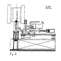
- Figure 2 is schematic diagram of a multichamber vertical injection machine according to one embodiment of the invention.
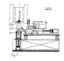
- Figure 3 is schematic diagram of a multichamber vertical injection machine according to one embodiment of the invention.
- Figure 4 is a detail view of the embodiment illustrated in Figure 2 also illustrating the preferred sprue arrangement.
- the present inventors have discovered an improved machine for manufacturing molded metallic parts that is capable of accurately metering metal and reducing or eliminating leakage.
- the machine includes a conduit between a melt feeder and a metering chamber and has a shutter rod disposed within it.
- the shutter rod has a valve head attached to a lower portion and is adapted to seal a lower portion of the conduit.
- This arrangement provides significantly better sealing than found in conventional multichamber injection machines. This, in turn, provides greater control over metering as will be discussed in more detail below.
- FIGs 1-4 illustrate a metal die casting machine according to one embodiment of the invention.
- the injection machine 200 of this embodiment includes a melt furnace 210 in which solid metal is melted to a liquid state.
- the solid metal may be ingot, pellet, powder or any other suitable metal source.
- the melt furnace has a heating source 205 which provides sufficient heat to liquefy the metal.
- the melt furnace 210 contains a plate 206 with an opening through which liquid metal can pass while solid metal sinks to the bottom of the melt furnace 210.
- Located below the melt furnace 210 is a metering chamber 220. Connecting the melt furnace 210 and the metering chamber 220 is a first conduit 215.
- the first conduit 215 has two portions.
- the first portion is a horizontal portion 214 connected to the melt furnace 210 and the second portion is a vertical portion 212 connected to the metering chamber 220.
- Disposed within the second portion 212 and adapted for axial movement is a shutter rod 217.
- Attached to a lower portion of the shutter rod 217 is a valve head 218.
- the valve head 218 is adapted to mate with a opening 219 ( Figure 2) in the lower part of the vertical portion 212 of the first conduit 215.
- the shape of the valve head 218 is an inverse of the opening 219 in the vertical portion 212 of the first conduit 215.
- the valve head 218 is conical with the wider part located below the narrower part.
- the valve head 218 may also be spherical, hemispherical or any other shape which can be adapted to seal the lower portion of the first conduit 215.
- the opening 219 provides access into the top of the metering chamber 220.
- the metering chamber 220 is preferably oriented horizontally.
- a second conduit 225 is located at one end of the metering chamber 220.
- the second conduit 225 connects the metering chamber 220 with the injection chamber 230.
- a metering rod 222 is located at the other end of the metering chamber 220.
- Surrounding a head of the metering rod 222 is at least one ring 221 to reduce or preferably eliminate leakage of liquid metal past the head of the metering rod 222.
- a plurality of rings may be used.
- the second conduit 225 connects to an opening 239 ( Figure 1) in a side wall of the injection chamber 230.
- the opening 239 is preferably located above the upper wall of the metering chamber 220 to avoid having metal flow from the metering chamber into the injection chamber 230 by the force of gravity.
- the conduit 225 is preferably inclined upwards from the metering chamber towards the injection chamber.
- the injection chamber 230 is preferably oriented vertically.
- At the upper end of the injection chamber 230 is an injection nozzle 240.
- At the lower end of the injection chamber 230 is a injection rod 237.
- the front face 231 of the injection rod 237 is substantially flat. However, the front face 231 of the injection rod 237 may have beveled edges.
- the injection machine 200 is mounted on a lifting base 260.
- the lifting base 260 contains components to lift the entire injection machine 200 toward a stationary mold 250 (typically comprising dies) having a mold cavity 255.
- the lifting components may be electronic, mechanical, hydraulic or any combination thereof.
- the injection machine 200 is held stationary and the mold 250 is configured to move relative to the injection machine 200.
- solid metal is charged into the melt furnace 210.
- the solid metal is charged into the right side of the melt furnace.
- the solid metal flows through the plate 206 into the left side of the melt furnace.
- the liquid metal flows into conduit 215.
- the liquid metal flows through the horizontal portion 214 and then fills the vertical portion 212.
- the shutter rod 217 is in a retracted position causing the valve head 218 to seal the opening 219 into the metering chamber 220.
- the metal does not flow into the metering chamber 220 from the conduit 215 ( Figure 1).
- the injection rod 237 is positioned in the injection chamber 230 such that a side of the injection rod 237 seals the opening 239 between the conduit 225 and the injection chamber, thus, preventing the flow of metal from the metering chamber 220 to the injection chamber 230.
- the metering rod 222 is positioned in a forward location with the front face of the metering rod 222 located slightly behind opening 219 of the metering chamber 220.
- the shutter rod 217 is lowered, breaking the seal between the valve head 218 and the opening 219 ( Figure 2).
- the metering rod 222 is retracted, creating suction which assists in drawing liquid metal from the melt furnace 210 through the conduit 21 5 into the metering chamber 220.
- the distance the metering rod 222 is retracted depends on the size of the required charge.
- the metering rod 222 could be fully retracted.
- the liquid metal flows into the metering chamber 220 due to gravity and due to suction created by retracting the metering rod 222. In this manner; the volume of the liquid metal in chamber 220 can be accurately controlled.
- the injection rod 237 in the injection chamber 230 is retracted from an upper position to a lower position to expose the opening 239 in the injection chamber 230.
- the metering rod 222 is then advanced to the position shown in Figure 1 to force a precisely metered amount of the liquid metal from the metering chamber 220 into the injection chamber 230.
- the advanced distance of the metering rod 222 corresponds to the required metal volume for a shot.
- the upper wall of the metering chamber is located below the opening 239 and the conduit 225 is inclined, metal does not flow from the metering chamber 220 into the injection chamber 230 due to gravity, thus allowing a precisely metered amount of the liquid metal to flow from the metering chamber 220 into the injection chamber 230 due to the forward movement of the metering rod 222.
- the injection rod 237 is slowly advanced to close the opening 239 in the injection chamber 230 and to drive off any air which remains in the injection chamber 230.
- the entire injection machine 200 is lifted toward the mold 250.
- the injection rod 237 is advanced upwards to inject liquid metal from the nozzle 240 into the mold 250 as shown in figure 1.
- the injection rod 237 is advanced at least 15, preferably at least 50 times as fast in the injection step as in the step of closing the opening 239.
- the mold 250 has an inverted sprue 254 having a roughly funnel shape with the wider opening 252 facing the injection nozzle 240 and the narrower opening 256 connecting to a gate 258.
- the injection machine 200 remains in the upper position until the casting and the gate 258 solidify. Then the injection rod 237 is lowered. Any molten metal remaining in the sprue 254 and the nozzle 240 falls back into the injection chamber 230. In this manner of operation, no solid plug is formed in the injection nozzle 240.
- the injection rod is lowered quickly and the nozzle 240 is separated from the mold 250 immediately after a gate 258 is solidified so that excessive heating of the dies and cooling of the nozzle 240 and the injection chamber 230 are avoided.
- molten or semi-solid metal in the sprue 254 and the nozzle 240 is sucked back to the injection chamber 230 by the retraction of the injection rod before the nozzle 240 is separated from the mold 250 to prevent formation of a solid plug.
- the semi-solid metal may then be re-melted with the next charge of liquid metal.
- the injection machine 200 is lowered.
- the mold 250 is opened and the molded part is removed while the metering chamber 220 is filled and a precisely metered amount of liquid metal is forced from the metering chamber 220 into the injection chamber 230 for the next cycle. Additionally, the dies which comprise the mold 250 are lubricated for the next casting.
Landscapes
- Engineering & Computer Science (AREA)
- Mechanical Engineering (AREA)
- Manufacturing & Machinery (AREA)
- Microelectronics & Electronic Packaging (AREA)
- Injection Moulding Of Plastics Or The Like (AREA)
- Casting Support Devices, Ladles, And Melt Control Thereby (AREA)
Abstract
Description
Claims (23)
- A vertical injection machine comprising:a first chamber for supplying liquid metal;a second chamber located lower than the first chamber;a first conduit connecting the first chamber to the second chamber, the first conduit having a shutter rod disposed therein;a valve head attached to a lower portion of the shutter rod, the valve head adapted to seal a lower portion of the first conduit;a metering rod disposed within the second chamber;a vertically oriented third chamber;a second conduit connecting the second chamber to the third chamber;an injection rod disposed vertically within the third chamber; anda injection nozzle located at an upper portion of the third chamber.
- The vertical injection machine of claim 1, wherein the first conduit comprises a horizontal portion connected to the first chamber and a vertical portion connected to the second chamber, wherein the shutter rod is disposed in the vertical portion.
- The vertical injection machine of claim 1, wherein the valve head is conical.
- The vertical injection machine of claim 1, further comprising heaters adjacent to the first chamber to melt sold metal.
- The vertical injection machine of claim 1, wherein the shutter rod is adapted to allow liquid metal to flow from the first chamber to the second chamber when the shutter rod is lowered to an open position.
- The vertical injection machine of claim 1, wherein the valve head seals the first conduit when the shutter rod is lifted to a closed position.
- The vertical injection machine of claim 1, further comprising a lifting mechanism wherein the lifting mechanism is adapted to lift the vertical injection machine towards a fixed mold.
- The vertical injection machine of claim 1, wherein the injection rod seals the second conduit when raised and the metering rod creates suction when withdrawn.
- A method of injection molding comprising:(A) melting metal into a liquid state in a first chamber;(B) passing a portion of the liquid metal to a first conduit;(C) allowing the portion of melted metal to flow from the first conduit into a second chamber located below the first chamber by opening a shutter disposed in the first conduit;(D) withdrawing a metering rod in the second chamber;(E) stopping a flow of metal from the first conduit into the second chamber by closing the shutter in the first conduit;(F) retracting an injection rod in a third chamber to expose a first opening from the second chamber into the third chamber;(G) advancing the metering rod to force the portion of metal from the second chamber to the third chamber via the first opening;(H) advancing the injection rod to close the first opening;(I) elevating the third chamber towards a stationary mold; and(J) advancing the injection rod to inject the portion of liquid metal from the third chamber through a nozzle into the mold.
- The method of claim 9, further comprising venting air in the third chamber by advancing the injection rod.
- The method of claim 9, further comprising elevating the first and the second chamber together with the third chamber.
- The method of claim 9, wherein the injection rod is advanced at least 15 times as fast in step (J) as in step (H).
- The method of claim 9, wherein withdrawing the metering rod is step (D) pulls the portion of liquid metal into the second chamber by suction.
- The method of claim 9, wherein a distanced advanced by the metering rod in step (G) determines the volume of metal forced into the third chamber.
- The method of claim 9, wherein the third chamber remains elevated until the metal in the mold solidifies.
- The method of claim 15, further comprising retracting the injection rod and lowering the third chamber away from the mold after the metal solidifies.
- The method of claim 16, wherein excess metal in mold falls back into the third chamber as the injection rod retracts.
- The method of claim 17, wherein excess metal in mold is sucked back into the third chamber by suction created by the retraction of the injection rod.
- The method of claim 18, further comprising separating the die, removing the solidified metal, and lubricating the mold.
- The method of claim 19, wherein steps (A) through (E) are performed at the same time as the steps of separating the die, removing the solidified metal, and lubricating the mold.
- The method of claim 9, wherein steps (A) through (E) are performed while the first opening is closed by the injection rod.
- The method of claim 9, wherein opening the shutter comprises lowering a shutter rod in the first conduit to open a seal between a shutter rod valve head and the first conduit, and closing the shutter comprises raising the shutter rod in the first conduit to form a seal between the shutter rod valve head and the first conduit.
- A vertical injection machine comprising:a first chamber containing a heating means for melting metal into a liquid state in a first chamber;a second chamber;a passing means for passing a portion of the liquid metal from the first chamber into the second chamber;a sealing means for sealing the passing means;a vertically oriented third chamber;a metering means for drawing in liquid metal from the first chamber into the second' chamber and for forcing the portion of metal from the second chamber to the third chamber;an injection means for sealing an opening between the third chamber and the second chamber and for injecting liquid metal from the third chamber into a mold; anda lifting means for lifting the vertical injection machine toward the mold prior to injecting the liquid metal into the mold and for lowering the vertical injection molding machine away from the mold after injecting the liquid metal into the mold.
Applications Claiming Priority (2)
| Application Number | Priority Date | Filing Date | Title |
|---|---|---|---|
| US440412 | 2003-05-19 | ||
| US10/440,412 US6880614B2 (en) | 2003-05-19 | 2003-05-19 | Vertical injection machine using three chambers |
Publications (2)
| Publication Number | Publication Date |
|---|---|
| EP1479464A2 true EP1479464A2 (en) | 2004-11-24 |
| EP1479464A3 EP1479464A3 (en) | 2005-10-19 |
Family
ID=33097939
Family Applications (1)
| Application Number | Title | Priority Date | Filing Date |
|---|---|---|---|
| EP04090146A Withdrawn EP1479464A3 (en) | 2003-05-19 | 2004-04-15 | Vertical injection molding machine using three chambers |
Country Status (6)
| Country | Link |
|---|---|
| US (1) | US6880614B2 (en) |
| EP (1) | EP1479464A3 (en) |
| JP (1) | JP2004344977A (en) |
| KR (1) | KR20040100916A (en) |
| CN (1) | CN1281361C (en) |
| TW (1) | TW200507966A (en) |
Cited By (6)
| Publication number | Priority date | Publication date | Assignee | Title |
|---|---|---|---|---|
| WO2004105979A2 (en) | 2003-06-03 | 2004-12-09 | Dong Keun Go | Die casting machine and casting method by thereof machine |
| DE102004057325A1 (en) * | 2004-11-27 | 2006-06-01 | Pfeiffer Vacuum Gmbh | Vacuum die casting process |
| WO2007038892A1 (en) * | 2005-10-04 | 2007-04-12 | Bühler Druckguss AG | Die casting method |
| WO2014201476A1 (en) * | 2013-06-20 | 2014-12-24 | Rosendahl Maschinen Gmbh | Method and device for casting connectors |
| CN106623839A (en) * | 2015-11-03 | 2017-05-10 | 广东科达洁能股份有限公司 | Novel casting molding machine |
| CN109093095A (en) * | 2018-11-03 | 2018-12-28 | 莆田市荣兴机械有限公司 | A kind of casting mould and preparation method thereof for horizontal liquor charging vertical injection |
Families Citing this family (6)
| Publication number | Priority date | Publication date | Assignee | Title |
|---|---|---|---|---|
| US6945310B2 (en) | 2003-05-19 | 2005-09-20 | Takata Corporation | Method and apparatus for manufacturing metallic parts by die casting |
| CN103978180A (en) * | 2014-06-04 | 2014-08-13 | 宁波中桥精密机械有限公司 | Air entrainment prevention aluminum alloy cold chamber die casting machine |
| CN103978182A (en) * | 2014-06-04 | 2014-08-13 | 宁波中桥精密机械有限公司 | Air entrapment prevention leak-proof material tube assembly of cold chamber die-casting machine |
| EP3655658B1 (en) * | 2017-07-20 | 2022-03-23 | Pyrotek, Inc. | Mold pump engagement apparatus and a method of filling a mold |
| CN108555263A (en) * | 2018-07-05 | 2018-09-21 | 中山市甘田电子机械设备有限公司 | Cold chamber die casting machine |
| CN116133772B (en) * | 2020-12-09 | 2025-09-16 | 浙江吉利控股集团有限公司 | Injection system and large-tonnage die casting machine |
Family Cites Families (142)
| Publication number | Priority date | Publication date | Assignee | Title |
|---|---|---|---|---|
| US2386966A (en) * | 1943-03-10 | 1945-10-16 | Hydraulic Dev Corp Inc | High-frequency electrostatic heating of plastics |
| US2505540A (en) * | 1945-02-15 | 1950-04-25 | Goldhard Franz Karl | Injection molding apparatus |
| US2529146A (en) * | 1948-03-15 | 1950-11-07 | Waldes Kohinoor Inc | Injection molding apparatus |
| US2758448A (en) * | 1954-04-16 | 1956-08-14 | Gen Electric | Household refrigerator |
| NL84643C (en) * | 1954-06-29 | |||
| US3874207A (en) * | 1957-10-22 | 1975-04-01 | Jerome H Lemelson | Extrusion apparatus |
| US3048892A (en) * | 1959-06-12 | 1962-08-14 | Copperweld Steel Co | Powder applicator |
| US3106002A (en) * | 1960-08-08 | 1963-10-08 | Nat Lead Co | Die-casting method |
| US3189945A (en) * | 1962-03-01 | 1965-06-22 | Pennsalt Chemicals Corp | Injection molding apparatus |
| US3123875A (en) * | 1962-05-31 | 1964-03-10 | Madwed | |
| US3254377A (en) * | 1963-04-22 | 1966-06-07 | Glenn R Morton | Fluid cooled, lubricated and sealed piston means for casting devices |
| US3344848A (en) * | 1963-06-24 | 1967-10-03 | Gen Motors Corp | Die casting apparatus with non-turbulent fill and dual shot plunger arrangement |
| US3270383A (en) * | 1963-06-24 | 1966-09-06 | Gen Motors Corp | Method of die casting |
| US3172174A (en) * | 1963-07-12 | 1965-03-09 | Automatic Casting Corp | Die casting apparatus |
| US3319702A (en) * | 1963-11-01 | 1967-05-16 | Union Carbide Corp | Die casting machine |
| US3270378A (en) * | 1964-01-16 | 1966-09-06 | Automatic Casting Corp | Die casting apparatus |
| US3286960A (en) | 1964-06-01 | 1966-11-22 | American Motors Corp | Compressor mounting spring |
| US3268960A (en) * | 1964-09-08 | 1966-08-30 | Glenn R Morton | Method of and means for producing dense articles from molten materials |
| US3201836A (en) * | 1964-09-21 | 1965-08-24 | Mount Vernon Die Casting Corp | Method of, and apparatus for, die casting metals |
| FR1447606A (en) | 1965-09-21 | 1966-07-29 | Buehler Ag Geb | Cold Room Die Casting Machine |
| DE1263995B (en) * | 1966-02-03 | 1968-03-21 | Volkswagenwerk Ag | Magnesium melting and charging system for die casting machines |
| US3491827A (en) * | 1966-07-12 | 1970-01-27 | Die Casting Machine Tools Ltd | Die casting machine with controlled injection |
| GB1173775A (en) * | 1966-09-06 | 1969-12-10 | Die Casting Machine Tools Ltd | Improvements in or relating to Die Casting Machines |
| US3447593A (en) * | 1967-05-25 | 1969-06-03 | Mt Vernon Die Casting Corp | Apparatus for die casting |
| CH470579A (en) | 1967-12-07 | 1969-03-31 | Linder Rene | Rotary volumetric machine |
| DE2017951C2 (en) * | 1970-04-15 | 1978-10-05 | Wotan-Werke Gmbh, 4000 Duesseldorf | Die casting machine with multiplier |
| US3550207A (en) | 1968-10-15 | 1970-12-29 | Pennwalt Corp | Sprue bushing purge port for injection molding machine |
| US3773873A (en) | 1970-06-22 | 1973-11-20 | Allied Chem | Method of injection molding foamable plastic with minimized wastage |
| US3810505A (en) * | 1970-12-07 | 1974-05-14 | R Cross | Die casting method |
| US3814170A (en) * | 1971-06-08 | 1974-06-04 | F Kahn | Apparatus for melting and casting material under pressure |
| US3976118A (en) * | 1971-06-08 | 1976-08-24 | Friedhelm Kahn | Method for casting material under pressure |
| US3893792A (en) * | 1973-04-06 | 1975-07-08 | Bbf Group Inc | Controller for injection molding machine |
| US3936298A (en) * | 1973-07-17 | 1976-02-03 | Massachusetts Institute Of Technology | Metal composition and methods for preparing liquid-solid alloy metal composition and for casting the metal compositions |
| US3902544A (en) * | 1974-07-10 | 1975-09-02 | Massachusetts Inst Technology | Continuous process for forming an alloy containing non-dendritic primary solids |
| US4049040A (en) * | 1975-08-07 | 1977-09-20 | N L Industries, Inc. | Squeeze casting apparatus and method |
| FR2368325A1 (en) * | 1976-10-25 | 1978-05-19 | Novatome Ind | MELTED METAL DOSING DEVICE |
| US4088178A (en) * | 1977-02-03 | 1978-05-09 | Ube Industries, Ltd. | Vertical die casting machines |
| US4212625A (en) * | 1978-03-14 | 1980-07-15 | Shutt George V | High speed injector for molding machines |
| GB2037634B (en) * | 1978-11-27 | 1983-02-09 | Secretary Industry Brit | Casting thixotropic material |
| JPS5594773A (en) * | 1979-01-09 | 1980-07-18 | Nissan Motor Co Ltd | Method and apparatus for die-casting |
| JPS5843177B2 (en) * | 1979-01-26 | 1983-09-26 | 本田技研工業株式会社 | How to fill molten metal in vertical die casting machine |
| DE2922914A1 (en) * | 1979-06-06 | 1980-12-11 | Oskar Frech Werkzeugbau Gmbh & | METHOD AND ARRANGEMENT FOR CONTROLLING THE INPRESSION PROCESS IN COLD CHAMBER DIE CASTING MACHINES |
| CA1149579A (en) * | 1979-07-26 | 1983-07-12 | Toyoaki Ueno | Vertical die casting machine |
| US4387834A (en) * | 1979-10-01 | 1983-06-14 | Hpm Corporation | Combination thermoplastic and glass loaded thermosetting injection molding machine and method for operating same |
| US4771818A (en) * | 1979-12-14 | 1988-09-20 | Alumax Inc. | Process of shaping a metal alloy product |
| US4476912A (en) * | 1980-10-14 | 1984-10-16 | Harvill John I | Hot chamber die casting machine |
| US4534403A (en) * | 1980-10-14 | 1985-08-13 | Harvill John I | Hot chamber die casting machine |
| US4694881A (en) * | 1981-12-01 | 1987-09-22 | The Dow Chemical Company | Method for making thixotropic materials |
| US4694882A (en) * | 1981-12-01 | 1987-09-22 | The Dow Chemical Company | Method for making thixotropic materials |
| US4537242A (en) * | 1982-01-06 | 1985-08-27 | Olin Corporation | Method and apparatus for forming a thixoforged copper base alloy cartridge casing |
| US4473103A (en) * | 1982-01-29 | 1984-09-25 | International Telephone And Telegraph Corporation | Continuous production of metal alloy composites |
| FR2521465A1 (en) * | 1982-02-12 | 1983-08-19 | Armines | PROCESS AND APPARATUS FOR MOLDING THIXOTROPIC METAL ALLOYS |
| JPS58212850A (en) | 1982-06-03 | 1983-12-10 | Toshiba Mach Co Ltd | Method for regulating injection condition automatically |
| JPS59152826U (en) | 1983-03-30 | 1984-10-13 | 富士通株式会社 | Clock oscillator control device |
| JPS60250867A (en) * | 1984-05-24 | 1985-12-11 | Nippon Denso Co Ltd | Method and device for die casting |
| US4635706A (en) * | 1985-06-06 | 1987-01-13 | The Dow Chemical Company | Molten metal handling system |
| EP0226830B1 (en) * | 1985-11-26 | 1990-01-10 | Akio Nakano | Injection apparatus in a hot chamber type die casting machine |
| JPS62161452A (en) * | 1986-01-10 | 1987-07-17 | Akio Nakano | Die casting machine |
| US4687042A (en) * | 1986-07-23 | 1987-08-18 | Alumax, Inc. | Method of producing shaped metal parts |
| DE3626990A1 (en) * | 1986-08-08 | 1988-02-18 | Krauss Maffei Ag | DEVICE FOR MIXING AT LEAST TWO REACTIVE PLASTIC COMPONENTS |
| US4828460A (en) * | 1986-08-13 | 1989-05-09 | Toshiba Kikai Kabushiki Kaisha | Electromagnetic pump type automatic molten-metal supply apparatus |
| JPH058016Y2 (en) | 1987-04-24 | 1993-03-01 | ||
| JPS63276523A (en) * | 1987-05-08 | 1988-11-14 | Komatsu Ltd | Control of injection molding machine |
| EP0295831B1 (en) | 1987-06-13 | 1993-03-17 | Honda Giken Kogyo Kabushiki Kaisha | Hydraulic control method for implements |
| JPH058017Y2 (en) | 1987-06-26 | 1993-03-01 | ||
| DE3891282C2 (en) * | 1987-07-09 | 1998-01-29 | Toshiba Machine Co Ltd | Molten metal feeder |
| JPH01166874A (en) | 1987-12-21 | 1989-06-30 | Akio Nakano | Casting device for composite metal product |
| JPH01178345A (en) | 1988-01-09 | 1989-07-14 | Ishikawajima Harima Heavy Ind Co Ltd | Quantitative dividing device for semi-solid metal slurry |
| JPH01192447A (en) | 1988-01-27 | 1989-08-02 | Agency Of Ind Science & Technol | Continuous forming method and device for metal slurry for continuous casting |
| JPH0667545B2 (en) * | 1988-06-10 | 1994-08-31 | 宇部興産株式会社 | Injection molding machine |
| JPH02202420A (en) | 1989-01-31 | 1990-08-10 | Sodick Co Ltd | Pressure measuring device of plasticizing material in injection molding and injection molding machine |
| US5040589A (en) * | 1989-02-10 | 1991-08-20 | The Dow Chemical Company | Method and apparatus for the injection molding of metal alloys |
| JPH02274360A (en) | 1989-04-12 | 1990-11-08 | Asahi Tec Corp | Molten metal pressurized casting method |
| IT1231211B (en) * | 1989-08-24 | 1991-11-23 | Tva Holding | PROCESS FOR CONTROLLED PRESSURE CASTING OF MELTED METALS, PARTICULARLY LIGHT ALLUMINIUM AND MAGNESIUM ALLOYS, AND EQUIPMENT FOR ITS EXECUTION |
| JPH0751827Y2 (en) | 1990-07-23 | 1995-11-22 | 株式会社ニフコ | PCB stop |
| US5109914A (en) * | 1990-09-04 | 1992-05-05 | Electrovert Ltd. | Injection nozzle for casting metal alloys with low melting temperatures |
| JPH0773788B2 (en) | 1990-09-05 | 1995-08-09 | 東芝機械株式会社 | Method of controlling die pressure pin of pressure casting machine |
| US5144998A (en) * | 1990-09-11 | 1992-09-08 | Rheo-Technology Ltd. | Process for the production of semi-solidified metal composition |
| CA2042184A1 (en) | 1990-09-20 | 1992-03-21 | Rex L. Bobsein | Process for preparing arylene sulfide sulfone copolymers |
| CA2053990A1 (en) | 1990-11-30 | 1992-05-31 | Gordon W. Breuker | Apparatus and process for producing shaped articles from semisolid metal preforms |
| CH682402A5 (en) * | 1990-12-21 | 1993-09-15 | Alusuisse Lonza Services Ag | A method for producing a liquid-solid metal alloy phase having thixotropic properties. |
| FR2671992B1 (en) | 1991-01-30 | 1997-08-01 | Transvalor Sa | COLD CHAMBER PRESSURE CASTING PROCESS. |
| JP2546077B2 (en) * | 1991-03-25 | 1996-10-23 | 宇部興産株式会社 | Mold casting equipment |
| US5181551A (en) * | 1991-09-25 | 1993-01-26 | Electrovert Ltd. | Double acting cylinder for filling dies with molten metal |
| US5551997A (en) * | 1991-10-02 | 1996-09-03 | Brush Wellman, Inc. | Beryllium-containing alloys of aluminum and semi-solid processing of such alloys |
| US5205338A (en) * | 1991-12-11 | 1993-04-27 | Nelson Metal Products Corporation | Closed shot die casting |
| WO1993013895A1 (en) * | 1992-01-13 | 1993-07-22 | Honda Giken Kogyo Kabushiki Kaisha | Method for casting aluminum alloy casting and aluminum alloy casting |
| US5388633A (en) * | 1992-02-13 | 1995-02-14 | The Dow Chemical Company | Method and apparatus for charging metal to a die cast |
| US5380187A (en) * | 1992-02-21 | 1995-01-10 | Sodick Co., Ltd. | Pre-plasticization type injection molding machine |
| US5575325A (en) * | 1993-02-03 | 1996-11-19 | Asahi Tec Corporation | Semi-molten metal molding method and apparatus |
| JP3176121B2 (en) | 1992-04-13 | 2001-06-11 | 本田技研工業株式会社 | Metal injection molding equipment |
| JP3139570B2 (en) | 1992-04-13 | 2001-03-05 | 本田技研工業株式会社 | Nozzle closing valve for metal injection molding equipment |
| US5577546A (en) | 1992-09-11 | 1996-11-26 | Comalco Aluminium Limited | Particulate feedstock for metal injection molding |
| JP3197109B2 (en) | 1993-04-21 | 2001-08-13 | 株式会社日本製鋼所 | Manufacturing method of alloy products |
| US5454423A (en) * | 1993-06-30 | 1995-10-03 | Kubota Corporation | Melt pumping apparatus and casting apparatus |
| EP0673699B1 (en) | 1993-09-16 | 2000-10-25 | Rheo-Technology, Ltd | Method of manufacturing thin cast piece through continuous casting |
| IT1260684B (en) * | 1993-09-29 | 1996-04-22 | Weber Srl | METHOD AND PLANT FOR THE DIE-CASTING OF SEMI-LIQUID COMPONENTS WITH HIGH MECHANICAL PERFORMANCE STARTING FROM REOCOLATED SOLID. |
| US5531261A (en) * | 1994-01-13 | 1996-07-02 | Rheo-Technology, Ltd. | Process for diecasting graphite cast iron at solid-liquid coexisting state |
| FR2715088B1 (en) * | 1994-01-17 | 1996-02-09 | Pechiney Aluminium | Process for shaping metallic materials in the semi-solid state. |
| US5413644A (en) * | 1994-01-21 | 1995-05-09 | Brush Wellman Inc. | Beryllium-containing alloys of magnesium |
| TW259748B (en) * | 1994-03-18 | 1995-10-11 | Nissei Zyushi Kogyo Kk | |
| JP3013226B2 (en) | 1994-04-28 | 2000-02-28 | 株式会社日本製鋼所 | Manufacturing method of metal molded products |
| US5697422A (en) | 1994-05-05 | 1997-12-16 | Aluminum Company Of America | Apparatus and method for cold chamber die-casting of metal parts with reduced porosity |
| US5501266A (en) * | 1994-06-14 | 1996-03-26 | Cornell Research Foundation, Inc. | Method and apparatus for injection molding of semi-solid metals |
| JP3107707B2 (en) * | 1994-06-29 | 2000-11-13 | トヨタ自動車株式会社 | Control method of pressure pin |
| JP2862799B2 (en) | 1994-09-05 | 1999-03-03 | 株式会社日本製鋼所 | Injection molding machine components |
| NO950843L (en) | 1994-09-09 | 1996-03-11 | Ube Industries | Method of Treating Metal in Semi-Solid State and Method of Casting Metal Bars for Use in This Method |
| IT1274912B (en) * | 1994-09-23 | 1997-07-25 | Reynolds Wheels Int Ltd | METHOD AND PLANT TO BRING SOLID OR SEMI-LIQUID SOLID STATE IN METAL ALLOY SUCH AS TABS, BILLETS AND SIMILAR, TO BE SUBJECTED TO THIXOTROPIC FORMING. |
| US5913353A (en) * | 1994-09-26 | 1999-06-22 | Ford Global Technologies, Inc. | Process for casting light metals |
| DE4440768C1 (en) * | 1994-11-15 | 1996-07-25 | Bachmann Giesserei & Formen | Device for casting metals |
| US5622216A (en) * | 1994-11-22 | 1997-04-22 | Brown; Stuart B. | Method and apparatus for metal solid freeform fabrication utilizing partially solidified metal slurry |
| US5630463A (en) * | 1994-12-08 | 1997-05-20 | Nelson Metal Products Corporation | Variable volume die casting shot sleeve |
| JPH08174172A (en) | 1994-12-20 | 1996-07-09 | Ube Ind Ltd | Low melting metal material casting method and casting machine |
| JP3228847B2 (en) | 1995-03-15 | 2001-11-12 | 株式会社日本製鋼所 | Metal injection molding method and apparatus |
| FR2731933B1 (en) * | 1995-03-22 | 2000-05-19 | Honda Motor Co Ltd | LINGOT HEATING METHOD AND ASSEMBLY |
| US5664618A (en) * | 1995-03-22 | 1997-09-09 | Honda Giken Kogyo Kabushiki Kaisha | Injection molding apparatus |
| JP3506800B2 (en) * | 1995-03-27 | 2004-03-15 | 東芝機械株式会社 | Injection control method and apparatus for die casting machine |
| US5571346A (en) | 1995-04-14 | 1996-11-05 | Northwest Aluminum Company | Casting, thermal transforming and semi-solid forming aluminum alloys |
| JP2976274B2 (en) * | 1995-05-29 | 1999-11-10 | 株式会社日本製鋼所 | Injection molding method and injection molding apparatus for low melting metal material |
| US5601136A (en) * | 1995-06-06 | 1997-02-11 | Nelson Metal Products Corporation | Inclined die cast shot sleeve system |
| US5730198A (en) * | 1995-06-06 | 1998-03-24 | Reynolds Metals Company | Method of forming product having globular microstructure |
| JP3817786B2 (en) * | 1995-09-01 | 2006-09-06 | Tkj株式会社 | Alloy product manufacturing method and apparatus |
| US5770245A (en) * | 1995-09-18 | 1998-06-23 | Nissei Plastic Industrial Co., Ltd. | Preplasticizing injection machine |
| JPH09155526A (en) | 1995-12-01 | 1997-06-17 | Japan Steel Works Ltd:The | Metal material injection equipment |
| JP3333673B2 (en) | 1995-12-01 | 2002-10-15 | 株式会社日本製鋼所 | Light alloy material injection molding method and apparatus |
| JP3494782B2 (en) | 1995-12-01 | 2004-02-09 | 株式会社日本製鋼所 | Screw removal method and device for injection molding machine |
| EP0859677B1 (en) | 1995-12-12 | 2002-03-13 | Thixomat, Inc. | Apparatus for processing semisolid thixotropic metallic slurries |
| CA2168685C (en) * | 1996-02-02 | 2000-06-20 | Gordon H. Woodhouse | Method and apparatus for supplying molten metal |
| US5730202A (en) * | 1996-03-18 | 1998-03-24 | Nelson Metal Products Corporation | Constant volume shot sleeve |
| JP3275052B2 (en) | 1996-03-19 | 2002-04-15 | 株式会社ユーモールド | Vertical die casting method and equipment |
| JP3011885B2 (en) | 1996-05-03 | 2000-02-21 | 株式会社日本製鋼所 | Manufacturing method of metal matrix composite material |
| US5711366A (en) | 1996-05-31 | 1998-01-27 | Thixomat, Inc. | Apparatus for processing corrosive molten metals |
| US5680894A (en) * | 1996-10-23 | 1997-10-28 | Lindberg Corporation | Apparatus for the injection molding of a metal alloy: sub-ring concept |
| AUPP060497A0 (en) | 1997-11-28 | 1998-01-08 | Commonwealth Scientific And Industrial Research Organisation | Magnesium pressure die casting |
| JP3254187B2 (en) * | 1997-12-08 | 2002-02-04 | 株式会社ソディック | Discharge method of leakage resin of pre-plastic injection molding machine and control device therefor |
| US6135196A (en) | 1998-03-31 | 2000-10-24 | Takata Corporation | Method and apparatus for manufacturing metallic parts by injection molding from the semi-solid state |
| US5983976A (en) | 1998-03-31 | 1999-11-16 | Takata Corporation | Method and apparatus for manufacturing metallic parts by fine die casting |
| US6334975B1 (en) * | 1998-10-26 | 2002-01-01 | Toshiba Kikai Kabushiki Kaisha | Molten magnesium supply system |
| JP3068600B1 (en) | 1999-03-19 | 2000-07-24 | 幸久 長子 | Automatic hot water injection system |
| JP2001150124A (en) | 1999-11-25 | 2001-06-05 | Toshiba Mach Co Ltd | Molten metal supply apparatus |
| JP2002137052A (en) | 2000-10-30 | 2002-05-14 | Toshiba Mach Co Ltd | Metal material supplying apparatus for casting equipment |
| JP2002273564A (en) | 2001-03-21 | 2002-09-25 | Aisin Seiki Co Ltd | Melt supply device |
-
2003
- 2003-05-19 US US10/440,412 patent/US6880614B2/en not_active Expired - Fee Related
-
2004
- 2004-04-15 EP EP04090146A patent/EP1479464A3/en not_active Withdrawn
- 2004-04-22 TW TW093111224A patent/TW200507966A/en unknown
- 2004-04-27 JP JP2004131737A patent/JP2004344977A/en active Pending
- 2004-05-13 KR KR1020040033778A patent/KR20040100916A/en not_active Withdrawn
- 2004-05-14 CN CNB2004100442319A patent/CN1281361C/en not_active Expired - Fee Related
Cited By (8)
| Publication number | Priority date | Publication date | Assignee | Title |
|---|---|---|---|---|
| WO2004105979A2 (en) | 2003-06-03 | 2004-12-09 | Dong Keun Go | Die casting machine and casting method by thereof machine |
| EP1663547A4 (en) * | 2003-06-03 | 2008-05-21 | Dong Keun Go | Die casting machine and casting method by thereof machine |
| DE102004057325A1 (en) * | 2004-11-27 | 2006-06-01 | Pfeiffer Vacuum Gmbh | Vacuum die casting process |
| WO2007038892A1 (en) * | 2005-10-04 | 2007-04-12 | Bühler Druckguss AG | Die casting method |
| WO2014201476A1 (en) * | 2013-06-20 | 2014-12-24 | Rosendahl Maschinen Gmbh | Method and device for casting connectors |
| CN105517731A (en) * | 2013-06-20 | 2016-04-20 | 罗森达尔耐科特洛姆有限公司 | Die casting method and die casting device |
| CN106623839A (en) * | 2015-11-03 | 2017-05-10 | 广东科达洁能股份有限公司 | Novel casting molding machine |
| CN109093095A (en) * | 2018-11-03 | 2018-12-28 | 莆田市荣兴机械有限公司 | A kind of casting mould and preparation method thereof for horizontal liquor charging vertical injection |
Also Published As
| Publication number | Publication date |
|---|---|
| CN1281361C (en) | 2006-10-25 |
| US20040231821A1 (en) | 2004-11-25 |
| CN1572391A (en) | 2005-02-02 |
| US6880614B2 (en) | 2005-04-19 |
| EP1479464A3 (en) | 2005-10-19 |
| KR20040100916A (en) | 2004-12-02 |
| TW200507966A (en) | 2005-03-01 |
| JP2004344977A (en) | 2004-12-09 |
Similar Documents
| Publication | Publication Date | Title |
|---|---|---|
| US7296611B2 (en) | Method and apparatus for manufacturing metallic parts by die casting | |
| US5244033A (en) | Diecasting apparatus | |
| US6880614B2 (en) | Vertical injection machine using three chambers | |
| EP1479465B1 (en) | Vertical injection machine and method | |
| US6123142A (en) | Method of molding articles to minimize shrinkage and voids | |
| CN108097921A (en) | Die casting feeding device and its method of feeding | |
| US3123875A (en) | Madwed | |
| US5662156A (en) | Method of die casting machine lubrication with unitized lubricant | |
| JP2013035008A (en) | Die casting machine and die casting method | |
| JP3842163B2 (en) | Die casting apparatus and die casting method | |
| JP4402007B2 (en) | Die casting apparatus and die casting method | |
| US20030094257A1 (en) | Shutterless injection molding method and apparatus | |
| JP7653829B2 (en) | Hot Chamber Casting Equipment | |
| JP2007190607A (en) | Die casting apparatus and die casting method | |
| JP4175602B2 (en) | Casting pouring equipment | |
| JP2965179B2 (en) | Mold casting equipment | |
| JP2008213009A (en) | Die casting device and die casting method | |
| JP2008264797A (en) | Die casting apparatus and die casting method | |
| JP2008264796A (en) | Vertical casting apparatus and vertical casting method | |
| KR20050042723A (en) | Injection molding device and injection molding method of metal material | |
| KR102932065B1 (en) | High-quality casting device and method for aluminum thick parts | |
| JP3477414B2 (en) | Injection molding method and apparatus |
Legal Events
| Date | Code | Title | Description |
|---|---|---|---|
| PUAI | Public reference made under article 153(3) epc to a published international application that has entered the european phase |
Free format text: ORIGINAL CODE: 0009012 |
|
| AK | Designated contracting states |
Kind code of ref document: A2 Designated state(s): AT BE BG CH CY CZ DE DK EE ES FI FR GB GR HU IE IT LI LU MC NL PL PT RO SE SI SK TR |
|
| AX | Request for extension of the european patent |
Extension state: AL HR LT LV MK |
|
| PUAL | Search report despatched |
Free format text: ORIGINAL CODE: 0009013 |
|
| AK | Designated contracting states |
Kind code of ref document: A3 Designated state(s): AT BE BG CH CY CZ DE DK EE ES FI FR GB GR HU IE IT LI LU MC NL PL PT RO SE SI SK TR |
|
| AX | Request for extension of the european patent |
Extension state: AL HR LT LV MK |
|
| AKX | Designation fees paid | ||
| STAA | Information on the status of an ep patent application or granted ep patent |
Free format text: STATUS: THE APPLICATION IS DEEMED TO BE WITHDRAWN |
|
| 18D | Application deemed to be withdrawn |
Effective date: 20060420 |
|
| REG | Reference to a national code |
Ref country code: DE Ref legal event code: 8566 |