EP1478878B1 - Ergonomic controls in a surgical lighting system - Google Patents
Ergonomic controls in a surgical lighting system Download PDFInfo
- Publication number
- EP1478878B1 EP1478878B1 EP03716140A EP03716140A EP1478878B1 EP 1478878 B1 EP1478878 B1 EP 1478878B1 EP 03716140 A EP03716140 A EP 03716140A EP 03716140 A EP03716140 A EP 03716140A EP 1478878 B1 EP1478878 B1 EP 1478878B1
- Authority
- EP
- European Patent Office
- Prior art keywords
- intensity
- handle
- light source
- lighting system
- lighthead
- Prior art date
- Legal status (The legal status is an assumption and is not a legal conclusion. Google has not performed a legal analysis and makes no representation as to the accuracy of the status listed.)
- Expired - Lifetime
Links
- 210000003813 thumb Anatomy 0.000 claims abstract description 7
- 238000000034 method Methods 0.000 claims description 15
- 230000007423 decrease Effects 0.000 claims description 14
- 230000003247 decreasing effect Effects 0.000 claims description 7
- 238000005286 illumination Methods 0.000 claims description 6
- 230000001954 sterilising effect Effects 0.000 claims description 6
- 230000004913 activation Effects 0.000 claims description 2
- 230000002035 prolonged effect Effects 0.000 claims 3
- 210000003811 finger Anatomy 0.000 abstract description 2
- 230000008901 benefit Effects 0.000 description 7
- 230000000994 depressogenic effect Effects 0.000 description 7
- 238000004659 sterilization and disinfection Methods 0.000 description 5
- 230000000694 effects Effects 0.000 description 4
- 239000012528 membrane Substances 0.000 description 4
- 230000000712 assembly Effects 0.000 description 3
- 238000000429 assembly Methods 0.000 description 3
- 238000001356 surgical procedure Methods 0.000 description 3
- 230000001351 cycling effect Effects 0.000 description 2
- 230000000881 depressing effect Effects 0.000 description 2
- 238000003825 pressing Methods 0.000 description 2
- 230000000007 visual effect Effects 0.000 description 2
- 239000000853 adhesive Substances 0.000 description 1
- 230000001070 adhesive effect Effects 0.000 description 1
- 230000009286 beneficial effect Effects 0.000 description 1
- 239000008280 blood Substances 0.000 description 1
- 210000004369 blood Anatomy 0.000 description 1
- 238000011109 contamination Methods 0.000 description 1
- 238000009429 electrical wiring Methods 0.000 description 1
- 230000004313 glare Effects 0.000 description 1
- 230000003760 hair shine Effects 0.000 description 1
- 210000004247 hand Anatomy 0.000 description 1
- 230000007246 mechanism Effects 0.000 description 1
- 230000008569 process Effects 0.000 description 1
- 238000000926 separation method Methods 0.000 description 1
- 239000000725 suspension Substances 0.000 description 1
- 230000002459 sustained effect Effects 0.000 description 1
- 239000012780 transparent material Substances 0.000 description 1
Images




Classifications
-
- F—MECHANICAL ENGINEERING; LIGHTING; HEATING; WEAPONS; BLASTING
- F21—LIGHTING
- F21S—NON-PORTABLE LIGHTING DEVICES; SYSTEMS THEREOF; VEHICLE LIGHTING DEVICES SPECIALLY ADAPTED FOR VEHICLE EXTERIORS
- F21S8/00—Lighting devices intended for fixed installation
-
- F—MECHANICAL ENGINEERING; LIGHTING; HEATING; WEAPONS; BLASTING
- F21—LIGHTING
- F21V—FUNCTIONAL FEATURES OR DETAILS OF LIGHTING DEVICES OR SYSTEMS THEREOF; STRUCTURAL COMBINATIONS OF LIGHTING DEVICES WITH OTHER ARTICLES, NOT OTHERWISE PROVIDED FOR
- F21V21/00—Supporting, suspending, or attaching arrangements for lighting devices; Hand grips
- F21V21/40—Hand grips
- F21V21/403—Hand grips for operation or dentist lamps
-
- F—MECHANICAL ENGINEERING; LIGHTING; HEATING; WEAPONS; BLASTING
- F21—LIGHTING
- F21V—FUNCTIONAL FEATURES OR DETAILS OF LIGHTING DEVICES OR SYSTEMS THEREOF; STRUCTURAL COMBINATIONS OF LIGHTING DEVICES WITH OTHER ARTICLES, NOT OTHERWISE PROVIDED FOR
- F21V21/00—Supporting, suspending, or attaching arrangements for lighting devices; Hand grips
- F21V21/40—Hand grips
-
- F—MECHANICAL ENGINEERING; LIGHTING; HEATING; WEAPONS; BLASTING
- F21—LIGHTING
- F21W—INDEXING SCHEME ASSOCIATED WITH SUBCLASSES F21K, F21L, F21S and F21V, RELATING TO USES OR APPLICATIONS OF LIGHTING DEVICES OR SYSTEMS
- F21W2131/00—Use or application of lighting devices or systems not provided for in codes F21W2102/00-F21W2121/00
- F21W2131/20—Lighting for medical use
- F21W2131/202—Lighting for medical use for dentistry
-
- F—MECHANICAL ENGINEERING; LIGHTING; HEATING; WEAPONS; BLASTING
- F21—LIGHTING
- F21W—INDEXING SCHEME ASSOCIATED WITH SUBCLASSES F21K, F21L, F21S and F21V, RELATING TO USES OR APPLICATIONS OF LIGHTING DEVICES OR SYSTEMS
- F21W2131/00—Use or application of lighting devices or systems not provided for in codes F21W2102/00-F21W2121/00
- F21W2131/20—Lighting for medical use
- F21W2131/205—Lighting for medical use for operating theatres
-
- Y—GENERAL TAGGING OF NEW TECHNOLOGICAL DEVELOPMENTS; GENERAL TAGGING OF CROSS-SECTIONAL TECHNOLOGIES SPANNING OVER SEVERAL SECTIONS OF THE IPC; TECHNICAL SUBJECTS COVERED BY FORMER USPC CROSS-REFERENCE ART COLLECTIONS [XRACs] AND DIGESTS
- Y10—TECHNICAL SUBJECTS COVERED BY FORMER USPC
- Y10S—TECHNICAL SUBJECTS COVERED BY FORMER USPC CROSS-REFERENCE ART COLLECTIONS [XRACs] AND DIGESTS
- Y10S362/00—Illumination
- Y10S362/804—Surgical or dental spotlight
Definitions
- the present invention relates to the surgical lighting and accessory control arts. It finds particular application in conjunction with controlling the intensity of light emanating from lightheads in an operating room (OR) setting and will be described with particular reference thereto. It is to be appreciated, however, that the invention also finds application in conjunction with controlling functions of other devices and is not limited to the aforementioned lighting application.
- large, high lumen output lightheads are used to illuminate the surgical site.
- the overhead lamps are turned off completely so that smaller, local light sources can be used or to help surgeons view monitor screens and other equipment.
- Light intensity controls in typical lighting systems are generally located in areas which are not directly accessible to the surgeon, such as on a non-sterile wall plate. To avoid potential contamination of the operating site, the surgeon requests a circulating nurse to adjust the non-sterile controls, as needed. This consumes both the nurse's time, and the surgeon's attention.
- a lighting system is known from GB 819 836 A .
- the housing of this light systems consists of a rear dome, a front dome and a circular support or bezel between these domes.
- the outside of the support is provided with a handle, formed as a bow, partially surrounding the support.
- the support further is equipped with two switches, positioned in the vicinity of the handle. Each of the switches allows to switch on and off a lamp, one of the lamps being equipped with a focussing device.
- the light system is destined to be used for dental surgeries.
- U.S. Patent No. 6,402,351 discloses a lighting system in which the light intensity control is located on a distal end of a sterile handle of the lighthead.
- a single push button at the tip of the lighthead handle is used to allow the surgeon to controls the intensity, cycling through discrete intensity levels with each push of the button.
- a primary disadvantage of this system is that it is very awkward to use. The hand must be inverted in order to position the user's thumb under the push button on the bottom of the lighthead handle. Additionally, the push-button mechanism creates surfaces where blood can become lodged, making sterilization for subsequent procedures difficult. Still further, functionally, the single push button allow only unidirectional light level cycling.
- the present invention provides new and improved ergonomic control methods and apparatus that overcome the above-referenced problems and others.
- a lighting system includes a lighthead including a housing, a light source disposed within the housing, a handle carried by the housing, adapted for grasping for moving the housing to selected positions, and a bezel.
- the handle is at least partially spaced from the housing by the bezel.
- An actuator on the bezel selectively adjusts an intensity of light emitted by the light source.
- the actuator includes first and second switching means. Actuation of the first switching means increases the intensity of the light emitted from the light source a selected amount between lower and upper intensity levels. Actuation of the second switching means decreases the intensity of the light emitted from the light source by a selected amount between upper and lower intensity levels.
- a method of adjusting illumination from a lighthead through a lens of the lighthead includes grasping a handle for moving the lighthead to selected positions and manipulating an actuator disposed between the handle and the lens to adjust an intensity of the illuminated light, the actuator being manipulatable using a thumb of a hand while grasping the handle.
- the manipulation includes actuating a first switching means, actuation of the first switch increasing the intensity of the light emitted from the light source a selected amount between lower and upper intensity levels, and actuating a second switching means, actuation of the second switching means decreasing the intensity of the light emitted from the light source by a selected amount between upper and lower intensity levels.
- a method of adjusting illumination from a lighthead includes covering a handle of a lighthead with a sterile cover and manipulating the handle to adjust a pattern size of illuminated light from a housing of the lighthead on a subject.
- the method further includes manipulating an actuator through the sterile cover to adjust an intensity of the illuminated light.
- the actuator is spaced from the handle such that the handle is removable from the housing without removing the actuator.
- a lighting system including a lighthead.
- the lighthead includes a housing.
- a light source is disposed within the housing.
- a bezel extends from the housing.
- a handle is rotatable relative to the housing and is at least partially spaced from the housing by the bezel.
- An actuator is associated with the bezel for adjusting an intensity of light emitted by the light source.
- a surgical light apparatus in accordance with another aspect of the present invention, includes a housing.
- a light source is located within the housing.
- a handle is carried by the housing for selectively focusing light from the light source.
- An actuator selectively adjusts an intensity of light emitted by the light source.
- the actuator is spaced from the handle such that the handle is removable from the housing without removing the actuator.
- a cover is selectively mountable on the handle such that the cover covers the actuator, whereby the actuator is operable by applying pressure on the cover adjacent the actuator.
- a surgical light apparatus of the type including a lighthead housing, a bulb located within the housing, a lens, a handle adjacent the lens, a bezel area between the handle and the lens, and a controller coupled to the bulb.
- An ergonomic control apparatus includes at least one actuator on the bezel area for controlling a function effected by the controller.
- One advantage of at least one embodiment of the present invention is the provision of an easily accessible light intensity control.
- Another advantage of at least one embodiment of the present invention is that the intensity control switches are located on the bezel area of a surgical lighthead.
- Another advantage of at least one embodiment of the present invention is that the handle is removable from the bezel without the need for disconnecting mechanical or electrical connections between the intensity control switches and the light source.
- an overhead lighting system 10 suited to use in an operating room illuminates areas of a patient 12 undergoing surgery.
- the system 10 illustrated in FIGURE 1 includes two lightheads 14, 16, which are suspended from a common mounting system 18 by articulated arm assemblies 20, 22, respectively.
- the arm assemblies allow the lightheads to be independently movable to a variety of positions relative to a ceiling 24 and the patient.
- the lighting system 10 is rigidly mounted to a suitable stationary support, such as a beam (not shown), typically located above the ceiling.
- the lighting system 10 may also include other medical devices, such as task lights, monitors, cameras, and the like (not shown).
- Each lighthead 14, 16 includes a housing 28 including a dome-shaped cover or shell 30, a lens system 32, through which the light shines from the respective lighthead, and a handle assembly 34, shown in detail in FIGURES 2 and 3 .
- a surgeon grasps a handle 36 of the handle assembly 34 and pulls the lighthead to the desired position.
- the housing shell 30 and lens system 32 together enclose a light source 38, such as one or more light bulbs or fiberoptic member.
- a reflector 40 directs the light from the light source 38 through the lens system 32.
- the lens system 32 includes two or more lenses, which are moved relative to each other, to adjust the focus of the light on the patient, e . g ., by decreasing or increasing the diameter of the light pattern on the patient. While the description refers to lighthead 14, shown in FIGURE 2 , it will be appreciated that the description applies as well to lighthead 16.
- the handle 36 is in the form of a generally cylindrical hollow shaft, which may be widened or otherwise shaped at its closed distal end 42 for ease of handling.
- the upper or proximal end of the handle widens to form a lip 44.
- a bezel or escutcheon 50 is mounted to or otherwise formed on the lighthead housing 28 such that it is located intermediate the housing and the handle 36.
- the bezel is mounted to the lighthead by bolts, screws, adhesive, or other suitable fixing means 51. In the illustrated embodiment, four screws 51 are used to attach the bezel to the lighthead, as will be described in greater detail below.
- the bezel 50 includes a frustoconically shaped distal end 52, which is adjacent to or in contact with the lip 44 of the handle 36.
- the handle 36 is rotatable, relative to the bezel 50, about an axis X through the lighthead, to adjust the focus of the lamp 38.
- the beam pattern emanating from the lighthead is thus adjusted by twisting the handle 36.
- the handle 36 can be rotatably mounted to the lighthead via a suitably positioned central opening 53 in the bezel 50, best shown in FIGURE 4 , and described in further detail below.
- a disposable sterile cover 54 (shown in phantom in FIGURE 2 and in perspective view in FIGURE 5 ) surrounds both the handle 36 and the bezel 50. Gripping regions 55 of the cover cooperate with corresponding regions (not shown) on the handle 36, to inhibit the cover from falling off the handle and to resist relative rotational movement between the cover and the handle, when the surgeon desires to twist the handle.
- the cover 54 has a sterile or highly disinfected outer surface 56 which the surgeon can handle repeatedly without risk of contaminating the surgeon's hands. When the surgeon grasps and rotates the handle 36, the cover 54 rotates along with the handle.
- the cover includes a generally cylindrical base portion 57, which covers the base 42, and sides of the handle 36, and a widened upper portion 58, which covers the widened upper portion 44 of the handle and the bezel 50.
- Lighting control input means 60 such as a plurality of membrane switches, are located on the bezel 50 of the lighthead handle assembly and serve as an actuator for the light source 38.
- the control input switches 60 are positioned to enable the surgeon to operate the switches while maintaining sterile technique by depressing the switches through the disposable cover 54.
- at least the upper portion 58 of the cover is sufficiently flexible or movable such that pressure on the cover adjacent the switches 60 allows the operation of the switches beneath.
- the cover is preferably formed from a transparent material so that the locations of the switches are readily visible therethrough.
- the switches 60 are used to control the intensity of the light emanating from the lighthead.
- the thumb is suitably positioned to depress the switches on the bezel above the handle.
- the relative position between the switches and the handle has ergonomic advantages and makes the switches extremely easy to operate and convenient to use.
- a transparent flexible annular membrane 66 formed from plastic or rubber, covers all of the switches 60 to provide an outer surface 68 which is easy to keep clean but which is sufficiently flexible to allow the switches to be actuated therethrough.
- the switches 60 are in the form of push buttons operable for an incremental increase or decrease in the light intensity with each successive depression of the button.
- the push buttons are operatively connected with a suitable controller 70, for example, by suitable electrical wiring 71.
- the controller is adapted to receive inputs from the buttons and react to those inputs to regulate the power supplied to the respective light source 38 of the lighthead to adjust the light intensity.
- the controller 70 may be located within the housing 28, such as between the reflector 40 and the dome 30 , as illustrated in FIGURE 3 , or located elsewhere, such as in the bezel 50, or spaced from the lighthead 14, 16 and electrically connected thereto.
- each set of switches 60, 62, 64 includes a first push button 74, which, when depressed, causes an increase in the light intensity between a low intensity and a maximum intensity.
- the controller 70 maintains the setting so that further pressing the increase intensity button 74 has no effect.
- a second push button 76 in each set 60, 62, 62 is a decrease intensity button, which when actuated, causes the light emanating from the light source 38 of the lighthead to decrease in intensity when depressed.
- the lighthead reaches its lowest intensity setting (a low level light)
- lightly depressing the decrease intensity button 76 has no effect.
- the button 76 is held in the depressed state for a predetermined period of time, such as about 1-2 seconds, the light source 38 is switched off.
- the controller 70 actuates an ambient light 80, contemporaneously with switching off the lighthead 14.
- the ambient light is spaced from the lighthead 14, 16 and provides overall low level room illumination.
- FIGURE 1 shows the ambient light 80 associatively coupled with the mounting system 18, although other locations for the ambient light are also contemplated.
- switching one of the lightheads 14 to off by the selectable lengthy time depression also switches off the other lighthead 16, regardless of its current intensity setting.
- Other arrangements are contemplated.
- sustained holding of the decrease button 76 for a first time period e.g., one (1) second
- depression for an additional selectable time period e.g., two to four (2-4) seconds
- the selectable delay interval time periods and other system parameters are preferably programmed into the controller software and are adjustable by changing or modifying the software.
- the time intervals are selectable from an input device associated with the controller 70 .
- buttons 74, 76 are suitably marked as desired with a visual indicator 81, such as a plus (+) or minus (-) symbol, as shown in FIGURE 2 to denote their function.
- the buttons are molded with raised indicators to provide for ready tactile recognition when the lighting level is low. The tactile differences also assist the surgeon in distinguishing the buttons when attention is focused elsewhere.
- the two buttons 74, 76 are shaped differently (oppositely pointing triangles in the illustrated embodiment), to facilitate identification by touch.
- Each of the buttons 74, 76 has a raised indicator 81 (v for decreasing intensity, ⁇ for increasing intensity in the illustrated embodiment).
- a separate power switch 82 is provided for switching the light source 38 on or off at any time.
- the power switch 82 is optionally mounted on the bezel 50, adjacent the switches 74, 76, as shown in FIGURE 6 . There may be more than one power switch 82, as for the other switches 74, 76.
- the power switch 82 is preferably readily distinguished, both visually and in by touch, from the other switches. In the illustrated embodiment it is different in color (e.g., red, blue, or green) from the switches 74, 76 and has a different shape--round, rather than triangular.
- a raised power symbol portion 84 is included in the center, for visual and tactile distinction.
- the power button 82 acts as a toggle switch.
- the power button 82 has the ability to control other lightheads 16 and/or other equipment as well. If the lightheads are on, and the power button 82 is depressed and held in a depressed condition for an extended period, then all the lightheads 14 , 16 are turned off by the associated controller 70. If the lightheads 14, 16 are off, and the power button 82 is depressed and held, all the lightheads are turned on. For example, all the lightheads are toggled if a power button is held for two (2) seconds. The time period for the function delay can be adjusted as desired.
- the controller 70 is adapted to receive input signals from the buttons 74, 76, 80 and respond to those signals to regulate the power to the respective lighthead light source to effect the desired operational function.
- additional control means such as push buttons 86, 88 are provided and are similarly connected to the controller to control devices and apparatus other than the associated lighthead such as, for example, video, audio, and other equipment.
- the physical location of the switches 74, 76, 82 on the bezel 50 has several advantages. First, it allows the switches to be covered by the thin flexible upper portion 58 of the disposable sterile cover 54 and thus remain outside the sterile field to enable activation of the switches without direct sterilization. Second, it permits a mechanical separation between the handle and the lighthead to allow the handle 36 to be readily removable from the bezel 50. Placing all the electrical connections within the bezel region allows them to remain with the lighthead 14 when the handle removed for sterilization. The handle can thus be subjected to repeated high level sterilization processes without posing risk of damage to electrical components. Third, placement of switches on the bezel is an ergonomically beneficial arrangement on a surgical lighthead which allows for ease of operation. The handle 36 can be loosely grasped while the switches 74, 76, 82 are comfortably activated using the natural motion of the upwardly extended thumb.
- buttons 74, 76, 84 on the bezel 50 allows the entire handle 36 and bezel 50 to be covered by a single disposable sterile cover 54.
- the preferred cover 54 is thin and easily slides over the handle 36, covering the entirety of the exposed portions of the bezel 50. This allows the surgeon to have immediate access to the lighting controls through the sterile cover while maintaining a sterile operating field. The cover, being disposable, is simply discarded after a surgery.
- the sterile cover 54 provides an interface between the sterile field on one side of the cover and non-sterile items on the non-sterile bezel 50.
- the bezel controller 70 is preferably separate from and not part of the removable lighthead handle 36 and need not be sterile.
- a master control unit 90 is in communication with each of the lightheads 14, 16 .
- the master control unit 90 may be mounted on a wall of the operating theater or at any other convenient location and includes a control panel 92, shown in greater detail in FIGURE 8 , for independently controlling each of the lightheads and other components of the system 10.
- the control panel includes a display screen 94 and a series of manually operable switches by which the lightheads and other components can be controlled. For example "select light" switches 96 and 98 allow an operator to toggle through the various lightheads (numbered 1-4 on the display panel) and select one of the lightheads. The operator can then use the intensity switches 100, 102 to vary the intensity of the light output on the selected lighthead.
- the intensity switches 100, 102 may be toggle switches which operate in a similar manner to intensity buttons 74, 76, sending signals to the controller 70. Either one of the switches of the master control unit 90 and the switches of the lighting control input means 60 can override the instructions of the other by being the latest in time to send a signal.
- a series of illuminated LED bars 104 associated with each lighthead on the display screen 94 provides an indication of the intensity of the light between zero (no bars illuminated 2), as in the case of lighthead No. 2, and maximum intensity (seven bars), as in the case of lighthead No. 1, in the illustrated embodiment.
- a function 106 labeled "all lights” allows all of the lightheads 14, 16 to be set to the same setting.
- communication cables 110, 112 extend between the master control 90 and the controller 70 in each lighthead for carrying signals therebetween.
- the controller 70 of one lighthead 14 receives a signal from the switch 76 to switch off the bulb 38 and also that of the other lighthead 16
- the controller sends a signal to the master control unit 90, which in turn signals the controller of the lighthead 16 to switch off the bulb of that lightheads.
- the master control unit 90 also signals the ambient light 80 to switch on.
- FIGURES 7 and 8 illustrate the subject ergonomic controls in a system 10 in which lightheads 14, 16 are mounted to a common hub 120 of the support system 18.
- a task light 122 and a lighthead 124 with a camera attachment 126 are also mounted to the common hub 120 by arm assemblies 128, 130. It will be appreciated that these and a variety of other components may all be controlled from the master control unit 90 as well as having separate, independent controllers associated with each component 14, 16, 122, 124.
- the bezel 50 and handle 36 are assembled on the lighthead, preferably as follows.
- the lighthead is fitted with a gearbox 140, which extends below the lens 32.
- a handle subassembly 144 is mounted to the gearbox 140. Specifically, threads 146 on the handle subassembly engage corresponding threads 148 on the gearbox 140.
- the bezel 50, with the membrane 66 attached, is mounted to a stationary housing 150 of the gearbox 140 using the screws 51 or other suitable fixing members.
- Keyhole slots 152 are formed on an inwardly extending rim 154 of the distal end 52 of the bezel, adjacent the opening 53, best shown in FIGURE 4 . The slots 152 receive the screws 51 therethrough.
- the wiring 71 from the bezel actuators 60 is connected with the controller 70.
- the handle subassembly 144 extends through the opening 53 in the bezel and is exteriorly threaded at 156.
- the handle 36 is interiorly threaded with corresponding threads at 158 which threadably engage the threads 156 as the handle is mounted on the handle subassembly 144.
- the lip 44 at the upper end of the handle covers the heads of the screws 51 and is seated against the distal end 52 of the bezel.
- the sterile cover 54 is pushed on to the handle 36 and bezel 50.
- the handle 36 can be readily removed from the handle subassembly 144, for sterilization, by rotating the handle to disengage the threads 158 from the subassembly threads 156.
- the handle and subassembly 144 rotate, conveying the rotation to the gearbox 140, which, in turn, adjusts the focus of the light from the lamp 38 on the patient.
- This adjustment may be achieved by adjusting the position of the lamp 38 relative to the reflector 40 or by adjusting the focusing of the lens system 32.
Landscapes
- Engineering & Computer Science (AREA)
- General Engineering & Computer Science (AREA)
- Non-Portable Lighting Devices Or Systems Thereof (AREA)
- Dental Tools And Instruments Or Auxiliary Dental Instruments (AREA)
Abstract
Description
- The present invention relates to the surgical lighting and accessory control arts. It finds particular application in conjunction with controlling the intensity of light emanating from lightheads in an operating room (OR) setting and will be described with particular reference thereto. It is to be appreciated, however, that the invention also finds application in conjunction with controlling functions of other devices and is not limited to the aforementioned lighting application.
- Typically, in an operating room setting, large, high lumen output lightheads are used to illuminate the surgical site. At certain times during an operation, it is appropriate for the surgeon to adjust the intensity of the light. For example, the surgeon may prefer a more intense overhead light to illuminate the operating region better, or the surgeon may desire to decrease the strength of the overhead light to reduce the effects of shadows or glare. In some situations, the overhead lamps are turned off completely so that smaller, local light sources can be used or to help surgeons view monitor screens and other equipment.
- Light intensity controls in typical lighting systems are generally located in areas which are not directly accessible to the surgeon, such as on a non-sterile wall plate. To avoid potential contamination of the operating site, the surgeon requests a circulating nurse to adjust the non-sterile controls, as needed. This consumes both the nurse's time, and the surgeon's attention.
- A lighting system according to the preamble of claim 1 is known from
GB 819 836 A -
U.S. Patent No. 6,402,351 discloses a lighting system in which the light intensity control is located on a distal end of a sterile handle of the lighthead. A single push button at the tip of the lighthead handle is used to allow the surgeon to controls the intensity, cycling through discrete intensity levels with each push of the button. A primary disadvantage of this system, however, is that it is very awkward to use. The hand must be inverted in order to position the user's thumb under the push button on the bottom of the lighthead handle. Additionally, the push-button mechanism creates surfaces where blood can become lodged, making sterilization for subsequent procedures difficult. Still further, functionally, the single push button allow only unidirectional light level cycling. - The present invention provides new and improved ergonomic control methods and apparatus that overcome the above-referenced problems and others.
- According to one aspect of the invention, a lighting system is provided. The lighting system includes a lighthead including a housing, a light source disposed within the housing, a handle carried by the housing, adapted for grasping for moving the housing to selected positions, and a bezel. The handle is at least partially spaced from the housing by the bezel. An actuator on the bezel selectively adjusts an intensity of light emitted by the light source. The actuator includes first and second switching means. Actuation of the first switching means increases the intensity of the light emitted from the light source a selected amount between lower and upper intensity levels. Actuation of the second switching means decreases the intensity of the light emitted from the light source by a selected amount between upper and lower intensity levels.
- In accordance with another aspect of the present invention, a method of adjusting illumination from a lighthead through a lens of the lighthead is provided. The method includes grasping a handle for moving the lighthead to selected positions and manipulating an actuator disposed between the handle and the lens to adjust an intensity of the illuminated light, the actuator being manipulatable using a thumb of a hand while grasping the handle. The manipulation includes actuating a first switching means, actuation of the first switch increasing the intensity of the light emitted from the light source a selected amount between lower and upper intensity levels, and actuating a second switching means, actuation of the second switching means decreasing the intensity of the light emitted from the light source by a selected amount between upper and lower intensity levels.
- In accordance with another aspect of the present invention, a method of adjusting illumination from a lighthead is provided. The method includes covering a handle of a lighthead with a sterile cover and manipulating the handle to adjust a pattern size of illuminated light from a housing of the lighthead on a subject. The method further includes manipulating an actuator through the sterile cover to adjust an intensity of the illuminated light. The actuator is spaced from the handle such that the handle is removable from the housing without removing the actuator.
- In accordance with another aspect of the present invention, a lighting system including a lighthead is provided. The lighthead includes a housing. A light source is disposed within the housing. A bezel extends from the housing. A handle is rotatable relative to the housing and is at least partially spaced from the housing by the bezel. An actuator is associated with the bezel for adjusting an intensity of light emitted by the light source.
- In accordance with another aspect of the present invention, a surgical light apparatus is provided. The light apparatus includes a housing. A light source is located within the housing. A handle is carried by the housing for selectively focusing light from the light source. An actuator selectively adjusts an intensity of light emitted by the light source. The actuator is spaced from the handle such that the handle is removable from the housing without removing the actuator. A cover is selectively mountable on the handle such that the cover covers the actuator, whereby the actuator is operable by applying pressure on the cover adjacent the actuator.
- In accordance with another aspect of the present invention, a surgical light apparatus of the type including a lighthead housing, a bulb located within the housing, a lens, a handle adjacent the lens, a bezel area between the handle and the lens, and a controller coupled to the bulb is provided. An ergonomic control apparatus includes at least one actuator on the bezel area for controlling a function effected by the controller.
- One advantage of at least one embodiment of the present invention is the provision of an easily accessible light intensity control.
- Another advantage of at least one embodiment of the present invention is that the intensity control switches are located on the bezel area of a surgical lighthead.
- Another advantage of at least one embodiment of the present invention is that the handle is removable from the bezel without the need for disconnecting mechanical or electrical connections between the intensity control switches and the light source.
- Still further advantages and benefits of the present invention will become apparent to those of ordinary skill in the art upon reading the following
- The invention may take form in various components and arrangements of components, and in various steps and arrangements of steps. The drawings are only for the purpose of illustrating preferred embodiments and are not to be construed as limiting the invention.
-
FIGURE 1 is a perspective view of a lighting system including a pair of lightheads connected to a suspension system in accordance with an embodiment of the invention; -
FIGURE 2 is a side view, in partial section of one of the lightheads ofFIGURE 1 ; -
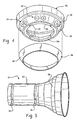
FIGURE 3 is an exploded perspective view of the lighthead ofFIGURE 2 ; -
FIGURE 4 is an enlarged perspective view of the bezel and bezel membrane ofFIGURE 3 ; -
FIGURE 5 is a perspective view of the sterile cover ofFIGURE 2 ; -
FIGURE 6 is an enlarged perspective view of the handle and bezel of an alternative embodiment of a lighthead according to the present invention; -
FIGURE 7 is a schematic view of a lighting system and master control unit according to another embodiment of the invention; -
FIGURE 8 is an enlarged view of the control panel ofFIGURE 7 ;and -
FIGURE 9 is a side sectional view of the bezel and handle mounted to a gearbox of the lighthead ofFIGURE 1 . - With reference to
FIGURE 1 , anoverhead lighting system 10 suited to use in an operating room illuminates areas of a patient 12 undergoing surgery. Thesystem 10 illustrated inFIGURE 1 includes twolightheads common mounting system 18 by articulatedarm assemblies ceiling 24 and the patient. Thelighting system 10 is rigidly mounted to a suitable stationary support, such as a beam (not shown), typically located above the ceiling. As will be appreciated, thelighting system 10 may also include other medical devices, such as task lights, monitors, cameras, and the like (not shown). - Each
lighthead housing 28 including a dome-shaped cover orshell 30, alens system 32, through which the light shines from the respective lighthead, and ahandle assembly 34, shown in detail inFIGURES 2 and3 . To maneuver a lighthead to a suitable location, a surgeon grasps ahandle 36 of thehandle assembly 34 and pulls the lighthead to the desired position. Thehousing shell 30 andlens system 32 together enclose alight source 38, such as one or more light bulbs or fiberoptic member. Areflector 40 directs the light from thelight source 38 through thelens system 32. In one embodiment, thelens system 32 includes two or more lenses, which are moved relative to each other, to adjust the focus of the light on the patient, e.g., by decreasing or increasing the diameter of the light pattern on the patient. While the description refers to lighthead 14, shown inFIGURE 2 , it will be appreciated that the description applies as well tolighthead 16. - The
handle 36 is in the form of a generally cylindrical hollow shaft, which may be widened or otherwise shaped at its closeddistal end 42 for ease of handling. The upper or proximal end of the handle widens to form alip 44. A bezel orescutcheon 50 is mounted to or otherwise formed on thelighthead housing 28 such that it is located intermediate the housing and thehandle 36. For example, the bezel is mounted to the lighthead by bolts, screws, adhesive, or other suitable fixing means 51. In the illustrated embodiment, fourscrews 51 are used to attach the bezel to the lighthead, as will be described in greater detail below. - The
bezel 50 includes a frustoconically shapeddistal end 52, which is adjacent to or in contact with thelip 44 of thehandle 36. Thehandle 36 is rotatable, relative to thebezel 50, about an axis X through the lighthead, to adjust the focus of thelamp 38. The beam pattern emanating from the lighthead is thus adjusted by twisting thehandle 36. By rotating thehandle 36, the pattern size of the illuminated light on the patient can be increased or decreased. Thehandle 36 can be rotatably mounted to the lighthead via a suitably positionedcentral opening 53 in thebezel 50, best shown inFIGURE 4 , and described in further detail below. - A disposable sterile cover 54 (shown in phantom in
FIGURE 2 and in perspective view inFIGURE 5 ) surrounds both thehandle 36 and thebezel 50. Grippingregions 55 of the cover cooperate with corresponding regions (not shown) on thehandle 36, to inhibit the cover from falling off the handle and to resist relative rotational movement between the cover and the handle, when the surgeon desires to twist the handle. Thecover 54 has a sterile or highly disinfectedouter surface 56 which the surgeon can handle repeatedly without risk of contaminating the surgeon's hands. When the surgeon grasps and rotates thehandle 36, thecover 54 rotates along with the handle. The cover includes a generallycylindrical base portion 57, which covers thebase 42, and sides of thehandle 36, and a widenedupper portion 58, which covers the widenedupper portion 44 of the handle and thebezel 50. - Lighting control input means 60, such as a plurality of membrane switches, are located on the
bezel 50 of the lighthead handle assembly and serve as an actuator for thelight source 38. The control input switches 60 are positioned to enable the surgeon to operate the switches while maintaining sterile technique by depressing the switches through thedisposable cover 54. Specifically, at least theupper portion 58 of the cover is sufficiently flexible or movable such that pressure on the cover adjacent theswitches 60 allows the operation of the switches beneath. The cover is preferably formed from a transparent material so that the locations of the switches are readily visible therethrough. - The
switches 60 are used to control the intensity of the light emanating from the lighthead. When the surgeon loosely grips the handle with the palm and fingers of the hand, the thumb is suitably positioned to depress the switches on the bezel above the handle. The relative position between the switches and the handle has ergonomic advantages and makes the switches extremely easy to operate and convenient to use. - As shown in
FIGURE 2 ,several sets bezel 50 so that a set of switches is readily accessed irrespective of the rotational position of the surgeon's hand. Additionally, a transparent flexibleannular membrane 66, formed from plastic or rubber, covers all of theswitches 60 to provide anouter surface 68 which is easy to keep clean but which is sufficiently flexible to allow the switches to be actuated therethrough. - In one embodiment, the
switches 60 are in the form of push buttons operable for an incremental increase or decrease in the light intensity with each successive depression of the button. The push buttons are operatively connected with asuitable controller 70, for example, by suitableelectrical wiring 71. The controller is adapted to receive inputs from the buttons and react to those inputs to regulate the power supplied to the respectivelight source 38 of the lighthead to adjust the light intensity. Thecontroller 70 may be located within thehousing 28, such as between thereflector 40 and thedome 30, as illustrated inFIGURE 3 , or located elsewhere, such as in thebezel 50, or spaced from thelighthead - In the embodiment of
FIGURE 2 , each set ofswitches first push button 74, which, when depressed, causes an increase in the light intensity between a low intensity and a maximum intensity. When the light emanating from the lighthead is at its maximum intensity available, thecontroller 70 maintains the setting so that further pressing theincrease intensity button 74 has no effect. - A
second push button 76 in each set 60, 62, 62 is a decrease intensity button, which when actuated, causes the light emanating from thelight source 38 of the lighthead to decrease in intensity when depressed. When the lighthead reaches its lowest intensity setting (a low level light), lightly depressing thedecrease intensity button 76 has no effect. However, if thebutton 76 is held in the depressed state for a predetermined period of time, such as about 1-2 seconds, thelight source 38 is switched off. Preferably, thecontroller 70 actuates anambient light 80, contemporaneously with switching off thelighthead 14. The ambient light is spaced from thelighthead -
FIGURE 1 shows theambient light 80 associatively coupled with the mountingsystem 18, although other locations for the ambient light are also contemplated. In one embodiment, switching one of thelightheads 14 to off by the selectable lengthy time depression also switches off theother lighthead 16, regardless of its current intensity setting. Other arrangements are contemplated. For example, sustained holding of thedecrease button 76 for a first time period, e.g., one (1) second, switches off just the associatedlighthead 14, while depression for an additional selectable time period, e.g., two to four (2-4) seconds, turns off all of the lightheads associated with thecontroller 70 and turns on the overheadambient light 80. The selectable delay interval time periods and other system parameters are preferably programmed into the controller software and are adjustable by changing or modifying the software. Alternatively, the time intervals are selectable from an input device associated with thecontroller 70. - The
buttons visual indicator 81, such as a plus (+) or minus (-) symbol, as shown inFIGURE 2 to denote their function. Preferably, the buttons are molded with raised indicators to provide for ready tactile recognition when the lighting level is low. The tactile differences also assist the surgeon in distinguishing the buttons when attention is focused elsewhere. Alternatively or additionally, as shown inFIGURE 6 , the twobuttons buttons - Optionally, a
separate power switch 82 is provided for switching thelight source 38 on or off at any time. Thepower switch 82 is optionally mounted on thebezel 50, adjacent theswitches FIGURE 6 . There may be more than onepower switch 82, as for theother switches power switch 82 is preferably readily distinguished, both visually and in by touch, from the other switches. In the illustrated embodiment it is different in color (e.g., red, blue, or green) from theswitches power symbol portion 84 is included in the center, for visual and tactile distinction. In one embodiment, thepower button 82 acts as a toggle switch. If it is depressed when thelighthead 14 is on, it turns the lighthead off. If it is depressed when thelighthead 14 is off, it turns the lighthead on. In the illustrated embodiment, thepower button 82 has the ability to control other lightheads 16 and/or other equipment as well. If the lightheads are on, and thepower button 82 is depressed and held in a depressed condition for an extended period, then all thelightheads controller 70. If the lightheads 14, 16 are off, and thepower button 82 is depressed and held, all the lightheads are turned on. For example, all the lightheads are toggled if a power button is held for two (2) seconds. The time period for the function delay can be adjusted as desired. - The
controller 70 is adapted to receive input signals from thebuttons push buttons - The physical location of the
switches bezel 50 has several advantages. First, it allows the switches to be covered by the thin flexibleupper portion 58 of the disposablesterile cover 54 and thus remain outside the sterile field to enable activation of the switches without direct sterilization. Second, it permits a mechanical separation between the handle and the lighthead to allow thehandle 36 to be readily removable from thebezel 50. Placing all the electrical connections within the bezel region allows them to remain with thelighthead 14 when the handle removed for sterilization. The handle can thus be subjected to repeated high level sterilization processes without posing risk of damage to electrical components. Third, placement of switches on the bezel is an ergonomically beneficial arrangement on a surgical lighthead which allows for ease of operation. Thehandle 36 can be loosely grasped while theswitches - The location of the
buttons bezel 50 allows theentire handle 36 andbezel 50 to be covered by a single disposablesterile cover 54. Thepreferred cover 54 is thin and easily slides over thehandle 36, covering the entirety of the exposed portions of thebezel 50. This allows the surgeon to have immediate access to the lighting controls through the sterile cover while maintaining a sterile operating field. The cover, being disposable, is simply discarded after a surgery. Thesterile cover 54 provides an interface between the sterile field on one side of the cover and non-sterile items on thenon-sterile bezel 50. Thebezel controller 70 is preferably separate from and not part of the removable lighthead handle 36 and need not be sterile. - With reference also to
FIGURES 7 and8 , amaster control unit 90 is in communication with each of thelightheads master control unit 90 may be mounted on a wall of the operating theater or at any other convenient location and includes acontrol panel 92, shown in greater detail inFIGURE 8 , for independently controlling each of the lightheads and other components of thesystem 10. The control panel includes adisplay screen 94 and a series of manually operable switches by which the lightheads and other components can be controlled. For example "select light" switches 96 and 98 allow an operator to toggle through the various lightheads (numbered 1-4 on the display panel) and select one of the lightheads. The operator can then use the intensity switches 100, 102 to vary the intensity of the light output on the selected lighthead. The intensity switches 100, 102 may be toggle switches which operate in a similar manner tointensity buttons controller 70. Either one of the switches of themaster control unit 90 and the switches of the lighting control input means 60 can override the instructions of the other by being the latest in time to send a signal. A series of illuminated LED bars 104 associated with each lighthead on thedisplay screen 94 provides an indication of the intensity of the light between zero (no bars illuminated 2), as in the case of lighthead No. 2, and maximum intensity (seven bars), as in the case of lighthead No. 1, in the illustrated embodiment. Afunction 106 labeled "all lights" allows all of thelightheads - As shown in
FIGURE 7 ,communication cables master control 90 and thecontroller 70 in each lighthead for carrying signals therebetween. For example, when thecontroller 70 of onelighthead 14 receives a signal from theswitch 76 to switch off thebulb 38 and also that of theother lighthead 16, the controller sends a signal to themaster control unit 90, which in turn signals the controller of thelighthead 16 to switch off the bulb of that lightheads. Themaster control unit 90 also signals theambient light 80 to switch on. These operations are carried out simultaneously or substantially so such that the operating room is not plunged in darkness for any significant length of time. - By way of example,
FIGURES 7 and8 illustrate the subject ergonomic controls in asystem 10 in which lightheads 14, 16 are mounted to acommon hub 120 of thesupport system 18. A task light 122 and alighthead 124 with acamera attachment 126 are also mounted to thecommon hub 120 byarm assemblies master control unit 90 as well as having separate, independent controllers associated with eachcomponent - With reference now to
FIGURE 9 , and reference also toFIGURES 3 and4 , thebezel 50 and handle 36 are assembled on the lighthead, preferably as follows. The lighthead is fitted with agearbox 140, which extends below thelens 32. Ahandle subassembly 144 is mounted to thegearbox 140. Specifically,threads 146 on the handle subassembly engage correspondingthreads 148 on thegearbox 140. Thebezel 50, with themembrane 66 attached, is mounted to astationary housing 150 of thegearbox 140 using thescrews 51 or other suitable fixing members.Keyhole slots 152 are formed on an inwardly extendingrim 154 of thedistal end 52 of the bezel, adjacent theopening 53, best shown inFIGURE 4 . Theslots 152 receive thescrews 51 therethrough. - The
wiring 71 from thebezel actuators 60 is connected with thecontroller 70. Thehandle subassembly 144 extends through theopening 53 in the bezel and is exteriorly threaded at 156. Thehandle 36 is interiorly threaded with corresponding threads at 158 which threadably engage thethreads 156 as the handle is mounted on thehandle subassembly 144. Thelip 44 at the upper end of the handle covers the heads of thescrews 51 and is seated against thedistal end 52 of the bezel. Finally, thesterile cover 54 is pushed on to thehandle 36 andbezel 50. Thehandle 36 can be readily removed from thehandle subassembly 144, for sterilization, by rotating the handle to disengage thethreads 158 from thesubassembly threads 156. - When the surgeon grasps and turns the
handle 36, the handle andsubassembly 144 rotate, conveying the rotation to thegearbox 140, which, in turn, adjusts the focus of the light from thelamp 38 on the patient. This adjustment may be achieved by adjusting the position of thelamp 38 relative to thereflector 40 or by adjusting the focusing of thelens system 32.
Claims (20)
- A lighting system (10) comprising a lighthead (14, 16, 124) including a housing (28), a light source (38) disposed within the housing for generating light, a lens (32) for transmitting said light from said lighthead, and a handle (36) carried by the housing, the handle being adapted for grasping by a hand of an operator for moving the housing to selected positions,
a bezel (50) located between the handle and the lens, the handle being at least partially spaced from the housing by the bezel,
an actuator (60, 62, 64), associated with the bezel, for selectively adjusting an intensity of light emitted by the light source by a thumb of the operator while grasping said handle, the actuator including
a first switching means (74) and
a second switching means (76)
the lighting system characterized by:the first switching means being an increase intensity button (74), actuation of the increase intensity button increasing and not decreasing the intensity of the light emitted from the light source by a selected amount between lower and upper intensity levels andthe second switching means being a decrease intensity button (76), actuation of the decrease intensity button decreasing and not increasing the intensity of the light emitted from the light source by a selected amount between upper and lower intensity levels. - The lighting system of claim 1, further characterized by:a controller (70) operatively coupled between the actuator and the light source and adapted to control the intensity of light emitted from the light source in response to actuation of the actuator.
- The lighting system of claim 2, further characterized by:the controller being adapted to modify the intensity of light emitted from the light source in response to successive actuations of the actuator in predefined increments of light intensity.
- The lighting system of either one of claims 2 and 3, further characterized by:the controller switching off the light source in response to a prolonged actuation of the decrease intensity button when the intensity of the light is at the lower intensity level.
- The lighting system of any one of claims 2-4, further characterized by:the controller applying power to an ambient lighting device (80), spaced from the lighthead, in response to a prolonged actuation of the decrease intensity button when the intensity of the light is at the lower intensity level.
- The lighting system of claim 5, further characterized by:the controller applying power to the ambient lighting device in response to the prolonged actuation of the decrease intensity button substantially simultaneously with switching off the light source.
- The lighting system of any one of preceding claims 1-6, further characterized by:the actuator further including:a power switch (82), actuation of the power switch (82), turning the light source off when the light source is on, actuation of the switching means turning the light source on when the light source is off.
- The lighting system of any one of preceding claims 1-7, further characterized by:the handle being rotatable relative to at least one of the bezel and the housing.
- The lighting system of any one of preceding claims 1-8, further characterized by:the handle being removable from the lighthead without disconnecting electrical connections between the actuator and the light source.
- The lighting system of claim 2, further characterized by:a second lighthead (16) including a second housing;a second light source disposed within the second lighthead housing, and wherein:the controller (70) is electrically coupled to the second light source and is adapted to control an intensity of light emitted from the second light source in response to selected activation of the actuator.
- The lighting system of claim 10, further characterized by:the second lighthead including a second actuator, operatively connected with the second light source by a second controller, for adjusting an intensity of light emitted by the second light source, each of the first and second actuators being operable to switch off the light source of the lighthead associated with the other of the first and second actuators.
- The lighting system of either one of preceding claims 10 and 11, further characterized by:the first and second lightheads being each mounted to a common support (18) by an articulated arm (20, 22).
- The lighting system of any one of preceding claims 1-12, further characterized by:the actuator including at least one switch 86, 88 for controlling operation of at least one of the group consisting of video equipment (126) and audio equipment.
- The lighting system of any one of claims 1-13, further characterized by:a sterile cover (54) selectively mountable on the handle and bezel such that the cover covers the actuator, the actuator being operable through the cover.
- The lighting system of any one of preceding claims 1-14, further characterized by:a gearbox for focusing the light from the light source, the gearbox being mounted to the housing;a handle subassembly mounted to the gearbox, rotation of the handle being conveyed to the gearbox by the handle subassembly, the handle subassembly extending through an opening in the bezel, the handle being removably mounted to the handle subassembly.
- The lighting system of claim 15, further characterized by:the lighthead housing including a reflector (40) and a lens system (32), rotation of the handle causing the gearbox to adjust the position of one lens of the lens system relative to another lens of the lens system, thereby adjusting the focus.
- The lighting system of any one of preceding claims 2-16, further characterized by:the controller (70) being operatively coupled between the actuator and the light source and controlling the intensity of the light source in response to an actuation of the actuator.
- A method of adjusting illumination from the lighting system (10) according to claim 1, the method comprising and being characterized by:manipulating the actuator (60) to adjust an intensity of the illuminated light, the actuator being manipulatable using a thumb of a hand while grasping said handle, said manipulation including:actuating the increase intensity button (74), only to increase the intensity of the light emitted from the light source; andactuating the decrease intensity button (76), only to decrease the intensity of the light emitted from the light source.
- The method of claim 18 for adjusting illumination from the lighting system (10) according to claims 1 and 9, the method being further characterized by:sterilizing a removed handle; andmounting the handle on the lighthead.
- The method of claim 18 for adjusting illumination from the lighting system (10) according to claims 1 and 14, the method being further characterized by:covering the handle (36) and the actuator (60) with the sterile cover (54);grasping the handle to position the lighthead and actuating the intensity increasing button (74) or the intensity decreasing button (76) through the sterile cover.
Applications Claiming Priority (3)
| Application Number | Priority Date | Filing Date | Title |
|---|---|---|---|
| US35949002P | 2002-02-25 | 2002-02-25 | |
| US359490P | 2002-02-25 | ||
| PCT/US2003/005489 WO2003072995A1 (en) | 2002-02-25 | 2003-02-05 | Ergonomic controls in a surgical lighting system |
Publications (2)
| Publication Number | Publication Date |
|---|---|
| EP1478878A1 EP1478878A1 (en) | 2004-11-24 |
| EP1478878B1 true EP1478878B1 (en) | 2008-05-14 |
Family
ID=27766095
Family Applications (1)
| Application Number | Title | Priority Date | Filing Date |
|---|---|---|---|
| EP03716140A Expired - Lifetime EP1478878B1 (en) | 2002-02-25 | 2003-02-05 | Ergonomic controls in a surgical lighting system |
Country Status (24)
| Country | Link |
|---|---|
| US (1) | US6863422B2 (en) |
| EP (1) | EP1478878B1 (en) |
| JP (1) | JP4133835B2 (en) |
| KR (1) | KR100602515B1 (en) |
| CN (1) | CN1643298A (en) |
| AT (1) | ATE395554T1 (en) |
| AU (1) | AU2003219860B2 (en) |
| BR (1) | BR0307927A (en) |
| CA (1) | CA2476529C (en) |
| CO (1) | CO5611221A2 (en) |
| DE (1) | DE60320950D1 (en) |
| EA (1) | EA006224B1 (en) |
| EC (1) | ECSP045251A (en) |
| ES (1) | ES2306862T3 (en) |
| GE (1) | GEP20074031B (en) |
| IL (1) | IL163640A0 (en) |
| MA (1) | MA27246A1 (en) |
| MX (1) | MXPA04008239A (en) |
| NO (1) | NO20044048L (en) |
| NZ (1) | NZ534742A (en) |
| PL (1) | PL371742A1 (en) |
| UA (1) | UA74977C2 (en) |
| WO (1) | WO2003072995A1 (en) |
| ZA (1) | ZA200406590B (en) |
Families Citing this family (48)
| Publication number | Priority date | Publication date | Assignee | Title |
|---|---|---|---|---|
| US7357811B2 (en) * | 2003-10-22 | 2008-04-15 | General Electric Company | Integrated procedure light for infant care apparatus |
| JP2005304906A (en) * | 2004-04-23 | 2005-11-04 | Toda Constr Co Ltd | Surgical lighting device |
| WO2005106699A1 (en) * | 2004-05-03 | 2005-11-10 | Lg Electronics Inc. | Method and apparatus for managing bookmark information for content stored in a networked media server |
| DE102004055839B4 (en) * | 2004-11-19 | 2011-06-16 | Dräger Medical GmbH | surgical light |
| DE102004055838B4 (en) * | 2004-11-19 | 2011-07-28 | Dräger Medical GmbH, 23558 | Operating light and control device |
| DE102005036275A1 (en) * | 2005-08-02 | 2007-02-08 | Berchtold Holding Gmbh | surgical light |
| EP1750052B1 (en) | 2005-08-06 | 2010-11-17 | TRUMPF Medizin Systeme GmbH + Co. KG | Surgical lamp |
| CN101317037B (en) | 2005-11-14 | 2012-01-25 | 通快医疗系统两合公司 | Operation luminaire system |
| CN101688651B (en) * | 2007-03-12 | 2011-06-15 | 美国消毒公司 | Internal cable management system for movable support arm |
| TWM327970U (en) * | 2007-10-02 | 2008-03-01 | Tien-Sheng Chen | Surgical operation illumination system with photographic recorder and lighting function |
| KR100900248B1 (en) * | 2008-03-17 | 2009-06-01 | 주식회사 큐레이 | Backlight unit with health care role |
| EP2136127B1 (en) * | 2008-06-20 | 2010-10-13 | TRUMPF Medizin Systeme GmbH + Co. KG | Operating light with illuminated handles |
| DE102008039772A1 (en) * | 2008-08-26 | 2010-03-04 | Berchtold Holding Gmbh | handle |
| US8070322B2 (en) * | 2008-09-11 | 2011-12-06 | Dental Equipment, Llc | Examination light with readily accessible controls |
| TW201017051A (en) * | 2008-10-17 | 2010-05-01 | Ind Tech Res Inst | Illumination system |
| US8622569B1 (en) * | 2009-07-17 | 2014-01-07 | Musco Corporation | Method, system and apparatus for controlling light distribution using swivel-mount led light sources |
| DE102010034562B8 (en) * | 2010-08-17 | 2017-08-31 | Drägerwerk AG & Co. KGaA | Operating light with improved operating functionality |
| DE102010060796A1 (en) * | 2010-11-25 | 2012-05-31 | Roland Sailer | Illumination arrangement for rescue workers, outdoor events, construction sites or halls, has multiple light modules and base body carrying light modules |
| DE102011075737A1 (en) * | 2010-12-23 | 2012-06-28 | Kaltenbach & Voigt Gmbh | Dental treatment light |
| US9687305B2 (en) | 2011-01-14 | 2017-06-27 | Ondal Holding Gmbh | Lighting device |
| US20130344795A1 (en) * | 2012-06-25 | 2013-12-26 | Huntair, Inc. | System and method for delivering air through a boom assembly |
| US8789243B2 (en) * | 2012-09-19 | 2014-07-29 | Ecolab Usa Inc. | Disposable handle cover for a surgical lighthead |
| US9470405B2 (en) | 2013-03-15 | 2016-10-18 | Stryker Corporation | Surgical light with beam redirecting optics |
| US9310096B2 (en) | 2013-08-22 | 2016-04-12 | Nortek Air Solutions, LLC. | Overhead support system having adjustable lighting elements |
| US9335447B2 (en) | 2013-11-21 | 2016-05-10 | Stryker Corporation | Fresnel lens with light-scattering preventive feature |
| US9945498B2 (en) | 2013-12-27 | 2018-04-17 | Stryker Corporation | Multi-stage rotary overtravel stop |
| WO2016058076A1 (en) * | 2014-10-14 | 2016-04-21 | Synaptive Medical (Barbados) Inc. | Patient reference tool |
| JP2017534359A (en) * | 2014-10-19 | 2017-11-24 | ベッツ,ジョシュア | Sterilization barrier for surgical lighting head |
| US10405414B2 (en) * | 2015-02-02 | 2019-09-03 | Amico Clinical Solutions Corporation | Lamp bypass switch |
| US10439611B2 (en) | 2015-02-11 | 2019-10-08 | Stryker Corporation | Sterile handle control mechanism |
| KR101726734B1 (en) | 2015-08-11 | 2017-04-13 | 주식회사 덴티스 | Device for coupling and decoupling handle of surgical light |
| ITUB20155377A1 (en) * | 2015-11-09 | 2017-05-09 | Rimsa P Longoni S R L | SCIALYTIC LED LAMP, PARTICULARLY FOR OPERATING AND SIMILAR ROOMS. |
| FR3044392B1 (en) * | 2015-11-26 | 2019-06-07 | Maquet Sas | LIGHTING APPARATUS WITH A REMOVABLE HANDLE |
| CN106813170A (en) * | 2015-12-02 | 2017-06-09 | 安钛医疗设备股份有限公司 | Operating lamp illumination control device |
| US9638406B1 (en) * | 2016-03-02 | 2017-05-02 | Amtai Medical Equipment, Inc. | Energy-saving device of surgical light |
| US9920922B2 (en) * | 2016-03-02 | 2018-03-20 | Amtai Medical Equipment, Inc. | Automatic light intensity compensating device of surgical light |
| US10603132B2 (en) | 2016-11-01 | 2020-03-31 | American Sterilizer Company | Lighthead identification system for lighthead control |
| DE102016013394A1 (en) | 2016-11-11 | 2018-05-17 | Drägerwerk AG & Co. KGaA | Protective cover for a part of a medical device |
| US10321970B1 (en) | 2018-01-09 | 2019-06-18 | American Sterilizer Company | Handle assembly for a surgical lighting system |
| US10650988B2 (en) * | 2018-01-09 | 2020-05-12 | American Sterilizer Company | Sterilizable handle actuating button integration |
| US10517158B2 (en) | 2018-02-09 | 2019-12-24 | Gentex Corporation | Systems and methods for detection and illumination of regions of interest |
| CN110800374B (en) * | 2018-05-15 | 2021-11-16 | 南京迈瑞生物医疗电子有限公司 | Operating lamp control method and operating lamp |
| AU2021214378B2 (en) | 2020-01-31 | 2024-02-29 | American Sterilizer Company | Lighting assembly and light head including same |
| WO2021194936A1 (en) * | 2020-03-27 | 2021-09-30 | American Sterilizer Company | 360 degrees plus rotation camera module for surgical light head handle |
| DE102020114425A1 (en) * | 2020-05-29 | 2021-12-02 | Karl Leibinger Medizintechnik Gmbh & Co. Kg | System for monitoring a surgical light arrangement |
| CN112303527A (en) * | 2020-10-28 | 2021-02-02 | 武汉大学 | Cardiovascular surgery LED lamp convenient to dismantle |
| EP4064796A1 (en) * | 2021-03-26 | 2022-09-28 | Stryker Corporation | Systems and methods for controlling a medical light via a software configurable handle assembly |
| CN113357576B (en) * | 2021-07-09 | 2023-03-24 | 胡珠 | Remote control adjustment operation shadowless lamp |
Family Cites Families (28)
| Publication number | Priority date | Publication date | Assignee | Title |
|---|---|---|---|---|
| US1918845A (en) * | 1929-11-13 | 1933-07-18 | S H Thomson Mfg Company | Electric switch mounting for vehicle spot lamps |
| US1996713A (en) * | 1933-05-25 | 1935-04-02 | Sandel Mfg Co | Lamp |
| US2069816A (en) | 1935-07-19 | 1937-02-09 | Air Devices Corp | Air conditioner |
| US2173325A (en) | 1936-02-24 | 1939-09-19 | American Sterilizer Co | Surgical operating luminaire |
| US2297781A (en) | 1940-06-24 | 1942-10-06 | John A Korengold | Lamp structure |
| US2632098A (en) * | 1949-09-14 | 1953-03-17 | Vincent J Marchese | Selectable switching means for stand lamps |
| GB739621A (en) * | 1953-02-05 | 1955-11-02 | Gilbert Francois Marius Grobel | Light projector |
| GB819836A (en) * | 1956-06-21 | 1959-09-09 | Emmanuel Quetin | Improvements in or relating to lighting apparatus for use in dental surgeries |
| DE1197827C2 (en) | 1964-04-11 | 1976-02-26 | Orginal Hanau Quarzlampen GmbH, 6450 Hanau | SURGICAL LIGHT |
| US3428797A (en) | 1965-10-21 | 1969-02-18 | American Sterilizer Co | Surgical light |
| FR2185929A5 (en) | 1972-05-26 | 1974-01-04 | Nelson Paul | |
| IT1106658B (en) * | 1978-05-24 | 1985-11-18 | Eurodent Di Conti Giacomo E C | ADJUSTABLE LUMINOUS FLOW LAMP |
| US4234907A (en) | 1979-01-29 | 1980-11-18 | Maurice Daniel | Light emitting fabric |
| DE3243709C3 (en) * | 1982-11-25 | 1994-12-15 | Delma Elektro Med App | Operating light |
| GB8308693D0 (en) | 1983-03-29 | 1983-05-05 | Oram J & D Ltd | Lamp |
| JPS62161382A (en) | 1986-01-13 | 1987-07-17 | 森 敬 | Light irradiating remedy cloth |
| US4795669A (en) * | 1987-01-28 | 1989-01-03 | Bowskill Mary J | Disposable protective shield for handle of illumination device |
| FR2657947B1 (en) * | 1990-02-06 | 1994-04-29 | Alm | PROJECTOR FOR MEDICAL USE, PARTICULARLY SURGICAL. |
| FR2684168B1 (en) | 1991-11-25 | 1994-04-01 | Distribution Mat Chirurgical | SURGICAL LIGHTING LAMP WITH AUTOMATIC MEANS FOR ADJUSTING THE CONCENTRATION OF LIGHT RAYS ON THE OPERATING FIELD. |
| US5339223A (en) | 1993-03-24 | 1994-08-16 | Ohmeda Inc. | Servocontrol for fiberoptic phototherapy pad |
| DE9308916U1 (en) | 1993-06-15 | 1993-12-09 | Streckbein, Roland, Dr.med. Dr.med.dent., 65582 Diez | Medical operating light |
| DE4338977C2 (en) * | 1993-11-15 | 1999-06-17 | Delma Elektro Med App | Luminaire for medical use |
| DE9317671U1 (en) | 1993-11-18 | 1994-02-24 | Delma Elektro- Und Medizinische Apparatebau Gmbh, 78532 Tuttlingen | Operating light |
| US6132062A (en) | 1998-03-27 | 2000-10-17 | Hill-Rom, Inc. | Task light for a surgical light apparatus |
| US6402351B1 (en) * | 1998-03-27 | 2002-06-11 | Hill-Rom Services, Inc., | Controls for a surgical light apparatus |
| CA2395377C (en) * | 1999-12-23 | 2008-02-19 | Hill-Rom Services, Inc. | Surgical theater system |
| US6715904B2 (en) * | 2001-07-19 | 2004-04-06 | Michael L. Naughton | Laser light handle |
| US6692141B2 (en) * | 2002-02-25 | 2004-02-17 | Steris Inc. | Disposable sterile cover for surgical lamps |
-
2003
- 2003-02-05 CN CNA038067269A patent/CN1643298A/en active Pending
- 2003-02-05 KR KR1020047013176A patent/KR100602515B1/en not_active Expired - Fee Related
- 2003-02-05 EA EA200401113A patent/EA006224B1/en unknown
- 2003-02-05 IL IL16364003A patent/IL163640A0/en unknown
- 2003-02-05 GE GEAP8417A patent/GEP20074031B/en unknown
- 2003-02-05 BR BR0307927-9A patent/BR0307927A/en not_active IP Right Cessation
- 2003-02-05 AT AT03716140T patent/ATE395554T1/en not_active IP Right Cessation
- 2003-02-05 JP JP2003571644A patent/JP4133835B2/en not_active Expired - Lifetime
- 2003-02-05 EP EP03716140A patent/EP1478878B1/en not_active Expired - Lifetime
- 2003-02-05 CA CA002476529A patent/CA2476529C/en not_active Expired - Lifetime
- 2003-02-05 MX MXPA04008239A patent/MXPA04008239A/en active IP Right Grant
- 2003-02-05 AU AU2003219860A patent/AU2003219860B2/en not_active Expired
- 2003-02-05 NZ NZ534742A patent/NZ534742A/en unknown
- 2003-02-05 WO PCT/US2003/005489 patent/WO2003072995A1/en not_active Ceased
- 2003-02-05 PL PL03371742A patent/PL371742A1/en unknown
- 2003-02-05 ES ES03716140T patent/ES2306862T3/en not_active Expired - Lifetime
- 2003-02-05 DE DE60320950T patent/DE60320950D1/en not_active Expired - Lifetime
- 2003-02-25 US US10/374,432 patent/US6863422B2/en not_active Expired - Lifetime
- 2003-05-02 UA UA20040807058A patent/UA74977C2/en unknown
-
2004
- 2004-08-18 ZA ZA200406590A patent/ZA200406590B/en unknown
- 2004-08-23 MA MA27836A patent/MA27246A1/en unknown
- 2004-08-25 EC EC2004005251A patent/ECSP045251A/en unknown
- 2004-09-22 CO CO04094459A patent/CO5611221A2/en unknown
- 2004-09-24 NO NO20044048A patent/NO20044048L/en not_active Application Discontinuation
Also Published As
| Publication number | Publication date |
|---|---|
| JP2005518261A (en) | 2005-06-23 |
| KR20040081804A (en) | 2004-09-22 |
| BR0307927A (en) | 2004-12-21 |
| KR100602515B1 (en) | 2006-07-19 |
| JP4133835B2 (en) | 2008-08-13 |
| AU2003219860B2 (en) | 2005-12-01 |
| EP1478878A1 (en) | 2004-11-24 |
| PL371742A1 (en) | 2005-06-27 |
| UA74977C2 (en) | 2006-02-15 |
| MA27246A1 (en) | 2005-03-01 |
| WO2003072995A1 (en) | 2003-09-04 |
| IL163640A0 (en) | 2005-12-18 |
| CO5611221A2 (en) | 2006-02-28 |
| GEP20074031B (en) | 2007-02-12 |
| ECSP045251A (en) | 2005-01-28 |
| ES2306862T3 (en) | 2008-11-16 |
| CA2476529C (en) | 2007-05-22 |
| US20030210559A1 (en) | 2003-11-13 |
| MXPA04008239A (en) | 2004-12-07 |
| CA2476529A1 (en) | 2003-09-04 |
| EA200401113A1 (en) | 2005-02-24 |
| ATE395554T1 (en) | 2008-05-15 |
| DE60320950D1 (en) | 2008-06-26 |
| CN1643298A (en) | 2005-07-20 |
| AU2003219860A1 (en) | 2003-09-09 |
| EA006224B1 (en) | 2005-10-27 |
| NZ534742A (en) | 2006-02-24 |
| ZA200406590B (en) | 2005-09-02 |
| US6863422B2 (en) | 2005-03-08 |
| NO20044048L (en) | 2004-11-24 |
Similar Documents
| Publication | Publication Date | Title |
|---|---|---|
| US6863422B2 (en) | Ergonomic controls in a surgical lighting system | |
| US6692141B2 (en) | Disposable sterile cover for surgical lamps | |
| US7746009B2 (en) | Operating lamp controls | |
| US8662719B2 (en) | Operating light with improved operating functionality | |
| EP1512158B1 (en) | Illuminated foot-switch | |
| US6132062A (en) | Task light for a surgical light apparatus | |
| HK1077618A (en) | Ergonomic controls in a surgical lighting system | |
| JP3598222B2 (en) | Lighting equipment | |
| HK1077619A (en) | Disposable sterile cover for surgical lamps |
Legal Events
| Date | Code | Title | Description |
|---|---|---|---|
| PUAI | Public reference made under article 153(3) epc to a published international application that has entered the european phase |
Free format text: ORIGINAL CODE: 0009012 |
|
| 17P | Request for examination filed |
Effective date: 20040831 |
|
| AK | Designated contracting states |
Kind code of ref document: A1 Designated state(s): AT BE BG CH CY CZ DE DK EE ES FI FR GB GR HU IE IT LI LU MC NL PT SE SI SK TR |
|
| AX | Request for extension of the european patent |
Extension state: AL LT LV MK RO |
|
| RIN1 | Information on inventor provided before grant (corrected) |
Inventor name: JESURUN, DAVID Inventor name: KESELMAN, YURY Inventor name: RUS, STEVEN, H. Inventor name: GRESZLER, ALLAN, J. Inventor name: DRABINSKI, TERRY, A. |
|
| GRAP | Despatch of communication of intention to grant a patent |
Free format text: ORIGINAL CODE: EPIDOSNIGR1 |
|
| GRAS | Grant fee paid |
Free format text: ORIGINAL CODE: EPIDOSNIGR3 |
|
| GRAA | (expected) grant |
Free format text: ORIGINAL CODE: 0009210 |
|
| AK | Designated contracting states |
Kind code of ref document: B1 Designated state(s): AT BE BG CH CY CZ DE DK EE ES FI FR GB GR HU IE IT LI LU MC NL PT SE SI SK TR |
|
| REG | Reference to a national code |
Ref country code: GB Ref legal event code: FG4D |
|
| REG | Reference to a national code |
Ref country code: CH Ref legal event code: EP |
|
| REG | Reference to a national code |
Ref country code: IE Ref legal event code: FG4D Free format text: LANGUAGE OF EP DOCUMENT: FRENCH |
|
| REF | Corresponds to: |
Ref document number: 60320950 Country of ref document: DE Date of ref document: 20080626 Kind code of ref document: P |
|
| PG25 | Lapsed in a contracting state [announced via postgrant information from national office to epo] |
Ref country code: SI Free format text: LAPSE BECAUSE OF FAILURE TO SUBMIT A TRANSLATION OF THE DESCRIPTION OR TO PAY THE FEE WITHIN THE PRESCRIBED TIME-LIMIT Effective date: 20080514 |
|
| PG25 | Lapsed in a contracting state [announced via postgrant information from national office to epo] |
Ref country code: FI Free format text: LAPSE BECAUSE OF FAILURE TO SUBMIT A TRANSLATION OF THE DESCRIPTION OR TO PAY THE FEE WITHIN THE PRESCRIBED TIME-LIMIT Effective date: 20080514 |
|
| NLV1 | Nl: lapsed or annulled due to failure to fulfill the requirements of art. 29p and 29m of the patents act | ||
| REG | Reference to a national code |
Ref country code: ES Ref legal event code: FG2A Ref document number: 2306862 Country of ref document: ES Kind code of ref document: T3 |
|
| PG25 | Lapsed in a contracting state [announced via postgrant information from national office to epo] |
Ref country code: AT Free format text: LAPSE BECAUSE OF FAILURE TO SUBMIT A TRANSLATION OF THE DESCRIPTION OR TO PAY THE FEE WITHIN THE PRESCRIBED TIME-LIMIT Effective date: 20080514 Ref country code: NL Free format text: LAPSE BECAUSE OF FAILURE TO SUBMIT A TRANSLATION OF THE DESCRIPTION OR TO PAY THE FEE WITHIN THE PRESCRIBED TIME-LIMIT Effective date: 20080514 |
|
| PG25 | Lapsed in a contracting state [announced via postgrant information from national office to epo] |
Ref country code: SE Free format text: LAPSE BECAUSE OF FAILURE TO SUBMIT A TRANSLATION OF THE DESCRIPTION OR TO PAY THE FEE WITHIN THE PRESCRIBED TIME-LIMIT Effective date: 20080814 Ref country code: DK Free format text: LAPSE BECAUSE OF FAILURE TO SUBMIT A TRANSLATION OF THE DESCRIPTION OR TO PAY THE FEE WITHIN THE PRESCRIBED TIME-LIMIT Effective date: 20080514 Ref country code: PT Free format text: LAPSE BECAUSE OF FAILURE TO SUBMIT A TRANSLATION OF THE DESCRIPTION OR TO PAY THE FEE WITHIN THE PRESCRIBED TIME-LIMIT Effective date: 20081014 Ref country code: CZ Free format text: LAPSE BECAUSE OF FAILURE TO SUBMIT A TRANSLATION OF THE DESCRIPTION OR TO PAY THE FEE WITHIN THE PRESCRIBED TIME-LIMIT Effective date: 20080514 |
|
| PG25 | Lapsed in a contracting state [announced via postgrant information from national office to epo] |
Ref country code: BE Free format text: LAPSE BECAUSE OF FAILURE TO SUBMIT A TRANSLATION OF THE DESCRIPTION OR TO PAY THE FEE WITHIN THE PRESCRIBED TIME-LIMIT Effective date: 20080514 Ref country code: SK Free format text: LAPSE BECAUSE OF FAILURE TO SUBMIT A TRANSLATION OF THE DESCRIPTION OR TO PAY THE FEE WITHIN THE PRESCRIBED TIME-LIMIT Effective date: 20080514 |
|
| PLBE | No opposition filed within time limit |
Free format text: ORIGINAL CODE: 0009261 |
|
| STAA | Information on the status of an ep patent application or granted ep patent |
Free format text: STATUS: NO OPPOSITION FILED WITHIN TIME LIMIT |
|
| 26N | No opposition filed |
Effective date: 20090217 |
|
| PG25 | Lapsed in a contracting state [announced via postgrant information from national office to epo] |
Ref country code: EE Free format text: LAPSE BECAUSE OF FAILURE TO SUBMIT A TRANSLATION OF THE DESCRIPTION OR TO PAY THE FEE WITHIN THE PRESCRIBED TIME-LIMIT Effective date: 20080514 Ref country code: BG Free format text: LAPSE BECAUSE OF FAILURE TO SUBMIT A TRANSLATION OF THE DESCRIPTION OR TO PAY THE FEE WITHIN THE PRESCRIBED TIME-LIMIT Effective date: 20080814 |
|
| PG25 | Lapsed in a contracting state [announced via postgrant information from national office to epo] |
Ref country code: MC Free format text: LAPSE BECAUSE OF NON-PAYMENT OF DUE FEES Effective date: 20090228 |
|
| REG | Reference to a national code |
Ref country code: CH Ref legal event code: PL |
|
| PG25 | Lapsed in a contracting state [announced via postgrant information from national office to epo] |
Ref country code: CH Free format text: LAPSE BECAUSE OF NON-PAYMENT OF DUE FEES Effective date: 20090228 Ref country code: LI Free format text: LAPSE BECAUSE OF NON-PAYMENT OF DUE FEES Effective date: 20090228 |
|
| PG25 | Lapsed in a contracting state [announced via postgrant information from national office to epo] |
Ref country code: IE Free format text: LAPSE BECAUSE OF NON-PAYMENT OF DUE FEES Effective date: 20090205 |
|
| REG | Reference to a national code |
Ref country code: GB Ref legal event code: 732E Free format text: REGISTERED BETWEEN 20100225 AND 20100303 |
|
| REG | Reference to a national code |
Ref country code: FR Ref legal event code: TP |
|
| PG25 | Lapsed in a contracting state [announced via postgrant information from national office to epo] |
Ref country code: GR Free format text: LAPSE BECAUSE OF FAILURE TO SUBMIT A TRANSLATION OF THE DESCRIPTION OR TO PAY THE FEE WITHIN THE PRESCRIBED TIME-LIMIT Effective date: 20080815 |
|
| PG25 | Lapsed in a contracting state [announced via postgrant information from national office to epo] |
Ref country code: LU Free format text: LAPSE BECAUSE OF NON-PAYMENT OF DUE FEES Effective date: 20090205 |
|
| PG25 | Lapsed in a contracting state [announced via postgrant information from national office to epo] |
Ref country code: HU Free format text: LAPSE BECAUSE OF FAILURE TO SUBMIT A TRANSLATION OF THE DESCRIPTION OR TO PAY THE FEE WITHIN THE PRESCRIBED TIME-LIMIT Effective date: 20081115 |
|
| PG25 | Lapsed in a contracting state [announced via postgrant information from national office to epo] |
Ref country code: TR Free format text: LAPSE BECAUSE OF FAILURE TO SUBMIT A TRANSLATION OF THE DESCRIPTION OR TO PAY THE FEE WITHIN THE PRESCRIBED TIME-LIMIT Effective date: 20080514 |
|
| PG25 | Lapsed in a contracting state [announced via postgrant information from national office to epo] |
Ref country code: CY Free format text: LAPSE BECAUSE OF FAILURE TO SUBMIT A TRANSLATION OF THE DESCRIPTION OR TO PAY THE FEE WITHIN THE PRESCRIBED TIME-LIMIT Effective date: 20080514 |
|
| REG | Reference to a national code |
Ref country code: DE Ref legal event code: R082 Ref document number: 60320950 Country of ref document: DE Representative=s name: VON KREISLER SELTING WERNER, DE Ref country code: DE Ref legal event code: R082 Ref document number: 60320950 Country of ref document: DE Representative=s name: VON KREISLER SELTING WERNER - PARTNERSCHAFT VO, DE Ref country code: DE Ref legal event code: R082 Ref document number: 60320950 Country of ref document: DE Representative=s name: DOMPATENT VON KREISLER SELTING WERNER - PARTNE, DE |
|
| REG | Reference to a national code |
Ref country code: FR Ref legal event code: PLFP Year of fee payment: 14 |
|
| REG | Reference to a national code |
Ref country code: FR Ref legal event code: PLFP Year of fee payment: 15 |
|
| REG | Reference to a national code |
Ref country code: FR Ref legal event code: PLFP Year of fee payment: 16 |
|
| PGFP | Annual fee paid to national office [announced via postgrant information from national office to epo] |
Ref country code: GB Payment date: 20220225 Year of fee payment: 20 Ref country code: DE Payment date: 20220225 Year of fee payment: 20 |
|
| PGFP | Annual fee paid to national office [announced via postgrant information from national office to epo] |
Ref country code: IT Payment date: 20220222 Year of fee payment: 20 Ref country code: FR Payment date: 20220223 Year of fee payment: 20 Ref country code: ES Payment date: 20220301 Year of fee payment: 20 |
|
| REG | Reference to a national code |
Ref country code: DE Ref legal event code: R071 Ref document number: 60320950 Country of ref document: DE |
|
| REG | Reference to a national code |
Ref country code: GB Ref legal event code: PE20 Expiry date: 20230204 |
|
| REG | Reference to a national code |
Ref country code: ES Ref legal event code: FD2A Effective date: 20230427 |
|
| PG25 | Lapsed in a contracting state [announced via postgrant information from national office to epo] |
Ref country code: GB Free format text: LAPSE BECAUSE OF EXPIRATION OF PROTECTION Effective date: 20230204 |
|
| PG25 | Lapsed in a contracting state [announced via postgrant information from national office to epo] |
Ref country code: ES Free format text: LAPSE BECAUSE OF EXPIRATION OF PROTECTION Effective date: 20230206 |