EP1478482B1 - Procede de suppression de defauts de moulage - Google Patents
Procede de suppression de defauts de moulage Download PDFInfo
- Publication number
- EP1478482B1 EP1478482B1 EP03702835A EP03702835A EP1478482B1 EP 1478482 B1 EP1478482 B1 EP 1478482B1 EP 03702835 A EP03702835 A EP 03702835A EP 03702835 A EP03702835 A EP 03702835A EP 1478482 B1 EP1478482 B1 EP 1478482B1
- Authority
- EP
- European Patent Office
- Prior art keywords
- casting defect
- casting
- defect
- melting
- article
- Prior art date
- Legal status (The legal status is an assumption and is not a legal conclusion. Google has not performed a legal analysis and makes no representation as to the accuracy of the status listed.)
- Expired - Lifetime
Links
- 230000007547 defect Effects 0.000 title claims abstract description 97
- 238000005266 casting Methods 0.000 title claims abstract description 74
- 238000000034 method Methods 0.000 title claims abstract description 59
- 238000002844 melting Methods 0.000 claims abstract description 41
- 230000008018 melting Effects 0.000 claims abstract description 36
- 239000012768 molten material Substances 0.000 claims abstract description 6
- 239000000463 material Substances 0.000 claims description 51
- 239000013078 crystal Substances 0.000 claims description 26
- 238000003466 welding Methods 0.000 claims description 20
- 238000007711 solidification Methods 0.000 claims description 19
- 230000008023 solidification Effects 0.000 claims description 19
- 208000003351 Melanosis Diseases 0.000 claims description 12
- 239000000843 powder Substances 0.000 claims description 12
- 239000011261 inert gas Substances 0.000 claims description 9
- 239000007787 solid Substances 0.000 claims description 8
- 229910000601 superalloy Inorganic materials 0.000 claims description 8
- PXHVJJICTQNCMI-UHFFFAOYSA-N Nickel Chemical compound [Ni] PXHVJJICTQNCMI-UHFFFAOYSA-N 0.000 claims description 6
- 239000007789 gas Substances 0.000 claims description 6
- 238000007689 inspection Methods 0.000 claims description 6
- 239000011148 porous material Substances 0.000 claims description 6
- 229910052721 tungsten Inorganic materials 0.000 claims description 5
- 238000003754 machining Methods 0.000 claims description 4
- 239000000203 mixture Substances 0.000 claims description 4
- 229910017052 cobalt Inorganic materials 0.000 claims description 3
- 239000010941 cobalt Substances 0.000 claims description 3
- GUTLYIVDDKVIGB-UHFFFAOYSA-N cobalt atom Chemical compound [Co] GUTLYIVDDKVIGB-UHFFFAOYSA-N 0.000 claims description 3
- 229910052759 nickel Inorganic materials 0.000 claims description 3
- 239000002002 slurry Substances 0.000 claims description 3
- WFKWXMTUELFFGS-UHFFFAOYSA-N tungsten Chemical compound [W] WFKWXMTUELFFGS-UHFFFAOYSA-N 0.000 claims description 3
- 239000010937 tungsten Substances 0.000 claims description 3
- 230000001419 dependent effect Effects 0.000 claims description 2
- 238000005530 etching Methods 0.000 claims description 2
- 229910045601 alloy Inorganic materials 0.000 description 15
- 239000000956 alloy Substances 0.000 description 15
- 239000007788 liquid Substances 0.000 description 10
- 206010014970 Ephelides Diseases 0.000 description 7
- 238000010438 heat treatment Methods 0.000 description 7
- 239000000155 melt Substances 0.000 description 6
- 238000001816 cooling Methods 0.000 description 5
- 230000035882 stress Effects 0.000 description 5
- 239000000758 substrate Substances 0.000 description 5
- 238000004519 manufacturing process Methods 0.000 description 4
- 230000005855 radiation Effects 0.000 description 4
- 230000015572 biosynthetic process Effects 0.000 description 3
- 239000000919 ceramic Substances 0.000 description 3
- 229910052751 metal Inorganic materials 0.000 description 3
- 239000002184 metal Substances 0.000 description 3
- 239000002344 surface layer Substances 0.000 description 3
- 239000013590 bulk material Substances 0.000 description 2
- 230000002349 favourable effect Effects 0.000 description 2
- 239000000945 filler Substances 0.000 description 2
- 238000000227 grinding Methods 0.000 description 2
- 238000005495 investment casting Methods 0.000 description 2
- 239000010410 layer Substances 0.000 description 2
- 230000035515 penetration Effects 0.000 description 2
- 229910001011 CMSX-4 Inorganic materials 0.000 description 1
- 229910003310 Ni-Al Inorganic materials 0.000 description 1
- 238000005162 X-ray Laue diffraction Methods 0.000 description 1
- 230000032683 aging Effects 0.000 description 1
- 230000009286 beneficial effect Effects 0.000 description 1
- 238000004140 cleaning Methods 0.000 description 1
- 239000011248 coating agent Substances 0.000 description 1
- 238000000576 coating method Methods 0.000 description 1
- 230000008602 contraction Effects 0.000 description 1
- 238000005336 cracking Methods 0.000 description 1
- 230000007423 decrease Effects 0.000 description 1
- 230000003247 decreasing effect Effects 0.000 description 1
- 230000002950 deficient Effects 0.000 description 1
- 210000001787 dendrite Anatomy 0.000 description 1
- 230000008021 deposition Effects 0.000 description 1
- 239000000428 dust Substances 0.000 description 1
- 230000005496 eutectics Effects 0.000 description 1
- 239000012530 fluid Substances 0.000 description 1
- 238000002347 injection Methods 0.000 description 1
- 239000007924 injection Substances 0.000 description 1
- 230000003993 interaction Effects 0.000 description 1
- 239000007791 liquid phase Substances 0.000 description 1
- 229910000907 nickel aluminide Inorganic materials 0.000 description 1
- 230000003287 optical effect Effects 0.000 description 1
- 230000003647 oxidation Effects 0.000 description 1
- 238000007254 oxidation reaction Methods 0.000 description 1
- 239000002245 particle Substances 0.000 description 1
- 239000012071 phase Substances 0.000 description 1
- 238000005498 polishing Methods 0.000 description 1
- 238000001953 recrystallisation Methods 0.000 description 1
- 230000003716 rejuvenation Effects 0.000 description 1
- 238000005204 segregation Methods 0.000 description 1
- 239000000243 solution Substances 0.000 description 1
- 238000011282 treatment Methods 0.000 description 1
Images

Classifications
-
- F—MECHANICAL ENGINEERING; LIGHTING; HEATING; WEAPONS; BLASTING
- F01—MACHINES OR ENGINES IN GENERAL; ENGINE PLANTS IN GENERAL; STEAM ENGINES
- F01D—NON-POSITIVE DISPLACEMENT MACHINES OR ENGINES, e.g. STEAM TURBINES
- F01D5/00—Blades; Blade-carrying members; Heating, heat-insulating, cooling or antivibration means on the blades or the members
- F01D5/005—Repairing methods or devices
-
- B—PERFORMING OPERATIONS; TRANSPORTING
- B22—CASTING; POWDER METALLURGY
- B22D—CASTING OF METALS; CASTING OF OTHER SUBSTANCES BY THE SAME PROCESSES OR DEVICES
- B22D19/00—Casting in, on, or around objects which form part of the product
- B22D19/10—Repairing defective or damaged objects by metal casting procedures
-
- B—PERFORMING OPERATIONS; TRANSPORTING
- B22—CASTING; POWDER METALLURGY
- B22D—CASTING OF METALS; CASTING OF OTHER SUBSTANCES BY THE SAME PROCESSES OR DEVICES
- B22D27/00—Treating the metal in the mould while it is molten or ductile ; Pressure or vacuum casting
- B22D27/04—Influencing the temperature of the metal, e.g. by heating or cooling the mould
- B22D27/045—Directionally solidified castings
-
- B—PERFORMING OPERATIONS; TRANSPORTING
- B23—MACHINE TOOLS; METAL-WORKING NOT OTHERWISE PROVIDED FOR
- B23K—SOLDERING OR UNSOLDERING; WELDING; CLADDING OR PLATING BY SOLDERING OR WELDING; CUTTING BY APPLYING HEAT LOCALLY, e.g. FLAME CUTTING; WORKING BY LASER BEAM
- B23K31/00—Processes relevant to this subclass, specially adapted for particular articles or purposes, but not covered by only one of the preceding main groups
- B23K31/02—Processes relevant to this subclass, specially adapted for particular articles or purposes, but not covered by only one of the preceding main groups relating to soldering or welding
-
- B—PERFORMING OPERATIONS; TRANSPORTING
- B23—MACHINE TOOLS; METAL-WORKING NOT OTHERWISE PROVIDED FOR
- B23P—METAL-WORKING NOT OTHERWISE PROVIDED FOR; COMBINED OPERATIONS; UNIVERSAL MACHINE TOOLS
- B23P6/00—Restoring or reconditioning objects
- B23P6/002—Repairing turbine components, e.g. moving or stationary blades, rotors
- B23P6/007—Repairing turbine components, e.g. moving or stationary blades, rotors using only additive methods, e.g. build-up welding
-
- C—CHEMISTRY; METALLURGY
- C30—CRYSTAL GROWTH
- C30B—SINGLE-CRYSTAL GROWTH; UNIDIRECTIONAL SOLIDIFICATION OF EUTECTIC MATERIAL OR UNIDIRECTIONAL DEMIXING OF EUTECTOID MATERIAL; REFINING BY ZONE-MELTING OF MATERIAL; PRODUCTION OF A HOMOGENEOUS POLYCRYSTALLINE MATERIAL WITH DEFINED STRUCTURE; SINGLE CRYSTALS OR HOMOGENEOUS POLYCRYSTALLINE MATERIAL WITH DEFINED STRUCTURE; AFTER-TREATMENT OF SINGLE CRYSTALS OR A HOMOGENEOUS POLYCRYSTALLINE MATERIAL WITH DEFINED STRUCTURE; APPARATUS THEREFOR
- C30B11/00—Single-crystal growth by normal freezing or freezing under temperature gradient, e.g. Bridgman-Stockbarger method
-
- C—CHEMISTRY; METALLURGY
- C30—CRYSTAL GROWTH
- C30B—SINGLE-CRYSTAL GROWTH; UNIDIRECTIONAL SOLIDIFICATION OF EUTECTIC MATERIAL OR UNIDIRECTIONAL DEMIXING OF EUTECTOID MATERIAL; REFINING BY ZONE-MELTING OF MATERIAL; PRODUCTION OF A HOMOGENEOUS POLYCRYSTALLINE MATERIAL WITH DEFINED STRUCTURE; SINGLE CRYSTALS OR HOMOGENEOUS POLYCRYSTALLINE MATERIAL WITH DEFINED STRUCTURE; AFTER-TREATMENT OF SINGLE CRYSTALS OR A HOMOGENEOUS POLYCRYSTALLINE MATERIAL WITH DEFINED STRUCTURE; APPARATUS THEREFOR
- C30B13/00—Single-crystal growth by zone-melting; Refining by zone-melting
-
- C—CHEMISTRY; METALLURGY
- C30—CRYSTAL GROWTH
- C30B—SINGLE-CRYSTAL GROWTH; UNIDIRECTIONAL SOLIDIFICATION OF EUTECTIC MATERIAL OR UNIDIRECTIONAL DEMIXING OF EUTECTOID MATERIAL; REFINING BY ZONE-MELTING OF MATERIAL; PRODUCTION OF A HOMOGENEOUS POLYCRYSTALLINE MATERIAL WITH DEFINED STRUCTURE; SINGLE CRYSTALS OR HOMOGENEOUS POLYCRYSTALLINE MATERIAL WITH DEFINED STRUCTURE; AFTER-TREATMENT OF SINGLE CRYSTALS OR A HOMOGENEOUS POLYCRYSTALLINE MATERIAL WITH DEFINED STRUCTURE; APPARATUS THEREFOR
- C30B29/00—Single crystals or homogeneous polycrystalline material with defined structure characterised by the material or by their shape
- C30B29/10—Inorganic compounds or compositions
- C30B29/52—Alloys
-
- C—CHEMISTRY; METALLURGY
- C30—CRYSTAL GROWTH
- C30B—SINGLE-CRYSTAL GROWTH; UNIDIRECTIONAL SOLIDIFICATION OF EUTECTIC MATERIAL OR UNIDIRECTIONAL DEMIXING OF EUTECTOID MATERIAL; REFINING BY ZONE-MELTING OF MATERIAL; PRODUCTION OF A HOMOGENEOUS POLYCRYSTALLINE MATERIAL WITH DEFINED STRUCTURE; SINGLE CRYSTALS OR HOMOGENEOUS POLYCRYSTALLINE MATERIAL WITH DEFINED STRUCTURE; AFTER-TREATMENT OF SINGLE CRYSTALS OR A HOMOGENEOUS POLYCRYSTALLINE MATERIAL WITH DEFINED STRUCTURE; APPARATUS THEREFOR
- C30B33/00—After-treatment of single crystals or homogeneous polycrystalline material with defined structure
-
- B—PERFORMING OPERATIONS; TRANSPORTING
- B23—MACHINE TOOLS; METAL-WORKING NOT OTHERWISE PROVIDED FOR
- B23K—SOLDERING OR UNSOLDERING; WELDING; CLADDING OR PLATING BY SOLDERING OR WELDING; CUTTING BY APPLYING HEAT LOCALLY, e.g. FLAME CUTTING; WORKING BY LASER BEAM
- B23K2101/00—Articles made by soldering, welding or cutting
- B23K2101/001—Turbines
-
- F—MECHANICAL ENGINEERING; LIGHTING; HEATING; WEAPONS; BLASTING
- F05—INDEXING SCHEMES RELATING TO ENGINES OR PUMPS IN VARIOUS SUBCLASSES OF CLASSES F01-F04
- F05D—INDEXING SCHEME FOR ASPECTS RELATING TO NON-POSITIVE-DISPLACEMENT MACHINES OR ENGINES, GAS-TURBINES OR JET-PROPULSION PLANTS
- F05D2300/00—Materials; Properties thereof
- F05D2300/60—Properties or characteristics given to material by treatment or manufacturing
- F05D2300/606—Directionally-solidified crystalline structures
Definitions
- the invention relates to a method of removing casting defects in articles with oriented microstructure.
- Single crystal and directionally solidified castings are manufactured using a directional solidification process in which a ceramic shell mould filled with an alloy in the liquid state is withdrawn from a heating zone (temperature above the melting point of the alloy) into a cooling zone (well below the melting point of the alloy in temperature).
- a heating zone temperature above the melting point of the alloy
- a cooling zone well below the melting point of the alloy in temperature.
- the liquid alloy solidifies directionally - beginning with that portion of the mould that enters the cooling zone first, and ending with the last portion of the mould to enter the cooling zone.
- the solid/liquid interface is found substantially at a level between the heating and cooling zones.
- Freckles are also considered critical defects in columnar grain alloys, despite their higher content of grain boundary strengtheners.
- new grains can nucleate and grow for a limited distance in the direction of growth of the solid/liquid interface, provided that the primary orientation (crystallographic orientation relative to the growth direction) is close to that of the rest of the casting.
- This defect is known as a sliver, and can reach lengths of 5 cm or more. Since it may comprise a high angle boundary which is almost always impossible to measure using Laue methods due to the limited width of the grain, slivers are also considered critical defects.
- Other grain related linear defects include low angle grain boundaries which are above the allowed limit of misorientation.
- Non grain related linear defects include linear chains of pores, surface micro-cracks and dross or inclusions which are normally only detectable using Flourescent Penetrant Inspection (FPI).
- FPI Flourescent Penetrant Inspection
- Another well known potential defect in single crystal and columnar-grained castings is recrystallized grains. Although these develop only during the solution heat treatment and/or reconditioning, repair, rejuvenation treatments, they can be considered casting defects since they are caused by excessive local deformation of the cast article due to the differential thermal contraction of the casting alloy, ceramic core and ceramic shell mold as the casting assembly cools. Recrystallized grains typically occur in the regions of highest deformation which are usually fillets, corners and design features which constrain the core or shell against the cast article.
- freckles are a well known problem as it is desirable to pull castings as quickly as possible into the cold zone, but more rapid withdrawal also results in lower thermal gradients across the solid-liquid interface.
- the rate of rejection can be anywhere from under 5% to over 50% depending on the alloy used and size of the article.
- the casting process parameters (including cluster size) are always developed in order to achieve a balance between production rate and the rate of rejection from casting defects to optimize overall process economics.
- EP-A1-0 558 870 describes free form welding of metallic articles with a laser where already built-up material acts as a substrate for newly deposited metal. However, the authors either use powder or wire feed and pulsed laser irradiation.
- EP-A1-0 740 977 furthermore describes a containerless method of producing crack free metallic articles using a laser beam operating at moderate power density. A large diameter beam produces a shallow melt pool from which single crystal articles are generated by addition of powder. The relatively long interaction time is claimed to be advantageous to reduce the cracks resulting from hot tearing defects during solidification. The method, however, focusses on the generation of new parts. Also the process parameters are chosen in order to reduce thermal gradients and thus stress, which is not favourable for single crystal solidification.
- US-A-5,837,960 describes a computer aided laser manufacturing process which is used to generate articles by laser/powder techniques. Again, the addition of powder is an essential part of that invention.
- US-A-5,312,584 describes a moldless/coreless method of producing single crystal castings of nickel-aluminides. In this case a laser is used to melt a Ni-Al target which melts, forms a drip and solidifies on an underlying single crystal substrate.
- DE-C1-199 49 972 uses a laser method to generate 3D objects using a digitizer/optical vision system and layer by layer material build-up.
- the method requires additional material supply which is not necessary for the local repair of casting defects.
- US-A-4 878 953 discloses a method for weld repairing defects in casting articles, in particular turbine components as blades of superalloy material which are directionally solidified or have a single crystal structure.
- the defect area is melted by means of a plasma arc into a shallow pool while welding powder having the same composition as the substrate superalloy material is delivered into the arc.
- the powder and the pool are permitted to solidify.
- the grains or crystals formed in the deposited metal grow with the same crystallographic orientation as in the grains in the substrate metal, i.e. epitaxially.
- the method may be conducted fully automated with a multi-axis robot.
- the object of the present invention is to provide a method for removing casting defects from a single crystal or a directionally solidified article with an oriented microstructure in an easy and cost-effective manner while restoring a defect-free grain structure and microstructure to the article.
- a method was found of removing casting defects from an article with an oriente microstructure which method is characterized in claim 1.
- the method comprises the steps of
- the advantage and new feature of this method compared to prior art is that it utilizes the material of the defect itself as the welding material.
- the defect comprises essentially identical material compared to the rest of the article, so melting and re-solidifying epitaxially into the oriented microstructure of the article results in a structure substantially identical to that of a cast article that never had defects in the first place.
- Re-melting the re-solidified portion of material again using a reduced energy density of the heat source compared to what was employed during the first melting operation, and again allowing it to solidify epitaxially with the surrounding defect free microstructure avoids the formation of a small surface layer of equiaxed grains during epitaxial solidification.
- the heat source can be moved along the length of the casting defect.
- the molten material solidifies epitaxially with respect to the surrounding oriented microstructure of the article in a way that the solidified area is restored substantially to a volume as it was with the casting defect.
- a casting defect of one of the following can be re-melted: a freckle, a sliver, an equiaxed or recrystallized grain, a linear crack, a surface micro-crack, a chain of pores, a linear dross inclusion or a linear cluster of inclusions.
- material is added before the melting operation in the form of a preform solid, powder compress, paste or slurry and used to fill at least a portion of the defect that was remelted. Additional material can also be added when no portion of any defect has been removed. This material can have substantially the same composition as the underlying article.
- the defect is melted and re-solidified, and then a second melting operation is carried out while this time adding additional material. After the solidification of the alloy, excess material is machined away e.g. by grinding.
- One embodiment of the invention is to remove a portion of the casting defect by machining before re-melting begins.
- a vision system can be used to record locations on a specific article when it is in the grain etched condition to reveal grain related defects such as freckles, slivers or small equiaxed grains or in Flourescent Penetrant Inspection (FPI) to reveal linear cracks, chains of pores or linear dross/inclusions and then, again, later used to guide the heat source to these areas for melting the casting defect.
- grain related defects such as freckles, slivers or small equiaxed grains or in Flourescent Penetrant Inspection (FPI) to reveal linear cracks, chains of pores or linear dross/inclusions and then, again, later used to guide the heat source to these areas for melting the casting defect.
- FPI Flourescent Penetrant Inspection
- the casting defect is locally melted by at least one laser or at least one of Plasma Transfer Arc Welding, Micro Plasma Welding, Tungsten Inert Gas Welding, Electron Beam Welding. This can be done under an inert gas atmosphere, with inert gas shielding, or under vacuum. Larger penetration depths can be achieved by further reducing the processing speed or by preheating the article prior to the melting of the casting defect to a desired temperature in the range of 500 - 1000°C.
- This method is preferably applied to the article such as gas turbine components made from a nickel or cobalt base super alloy.
- These articles have a single crystal (SX) or directionally solidified (DS) microstructure.
- Figure 1 shows a single crystal (SX) or directionally solidified (DS) article 1 such as blades or vanes of gas turbine engines, the gas turbine blade comprising a root portion 2, a platform 3 and a blade 4 and having a surface 6.
- the article can as an example be made from a nickel or cobalt based super alloy.
- Investment casting methods for producing such SX or DS articles are known e.g. from the prior art US-A-4,96,501, US-A-3,690,367 or EP-A1-0 749 790.
- the article 1 exhibits a linear casting defect 5 such as a freckle, a sliver or any equiaxed or recrystallized grains of limited size somewhere after the production process.
- Non grain related linear defects include linear chains of pores, surface micro-cracks and dross or inclusions.
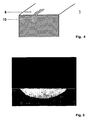
- Figures 3 and 4 show the different steps of removing the casting defect 5 according to the present invention.
- a casting defect 5 is detected.
- Casting defects 5 are easily detected by using grain etching methods commonly known to those skilled in the art.
- Non grain related linear defects including linear chains of pores, surface micro-cracks and dross, inclusions or a linear cluster of inclusions are normally only detectable using Flourescent Penetrant Inspection (FPI).
- FPI Flourescent Penetrant Inspection
- the extremities may be demarcated with scribe marks or other such visible means such that after polishing or abrasive cleaning the site of the casting defect 5 is still apparent. It is also possible to leave a light grain etch on the surface and use that to weld in the correct areas. In either case, a vision system may be used to assist in the welding process. The system may be used to first record the position of the casting defect 5 (no marks are required) in the grain etched state and then used to guide the source of heat later for the repair operation.
- the article 1 is melted from the surface 6 in the region of the casting defect 5 by the use of a locally acting heat source 7, e.g. a laser, to a depth at least as great as the casting defect 5 itself.
- the heat source 7 reheats the affected zone above the melting point. If during this operation the ratio G n /V s (where G is the temperature gradient in the melt pool, n is a material constant and V s is the solidification speed) is kept above a material dependent threshold value, the subsequent solidification (as indicated in Figure 4 with repaired zone 10) will occur epitaxially, i.e. without creating new grain boundaries.
- the surrounding single crystal bulk material will act as a crystal seed for the remolten material. After solidification the remolten material will have the same microstructure as the bulk material without any defect so that the oriented microstructure is substantially restored to a volume as it used to be with the casting defect 5. The casting defect 5 will be thus remedied.
- lasers offer a particularly attractive choice for the heat source 7.
- Laser radiation can be focussed to small spots and generate thermal gradients in excess of 10 6 K/m. It is beneficial if the laser intensity is uniform over the heated area, which can be achieved by fiberoptic beam delivery. As laser power is very easily controlled, it is ensured that the criterion for single crystal solidification is maintained during the whole repair operation. As an additional consequence the boundaries that have been set by the vision system do not have to be rigorously kept. If the heat source 7 acts on zones without casting defects 5 the material will be also remolten and it will subsequently resolidify with its original orientation.
- the melting of whole areas of limited size can as well be achieved by parallel, partially overlapping laser remelting tracks, for example when repairing clusters of freckles in close proximity, wide slivers, and shallow equiaxed grains.
- the overlap is typically 30%-50%.
- the laser will be focussed to a spot size of 1-2mm diameter.
- the laser would be either of the Nd-YAG or high power diode laser type. These lasers operate in the near infrared and about 30-40% of the incident radiation is absorbed by typical super alloys.
- the laser beam will move at relatively slow speeds (approx. 1-10 mm/s) over the affected zones and operate in the conduction welding mode. Laser intensities of 1*10 3 W/cm 2 to 5*10 4 W/cm 2 will remelt a zone reaching up to 500 ⁇ m below the surface.
- At least one of Plasma Transfer Arc Welding, Micro Plasma Welding, Tungsten Inert Gas Welding, Electron Beam Welding are any other suitable tool can be used.
- the welding can be carried out under an inert gas atmosphere, with inert gas shielding, or under vacuum to prevent excessive oxidation of the liquid alloy.
- the article can be prepared before the melting of the casting defects by stress relief heat treatments to temperatures close to the incipient melting point.
- additional material 8 can be added to the already molten area by means of a feeder 9 to ensure the monocrystalline structure of the underlying material.
- a feeder 9 to ensure the monocrystalline structure of the underlying material.
- material is added before the melting operation in the form of a preform solid, powder compress, paste or slurry and used to fill at least a portion of the defect that was remelted. Additional material can also be added when no portion of any defect has been removed. With advantage, additional material 8 with substantially the same composition as the article itself is fed to the locally melted area.
- the defect comprises essentially identical material compared to the rest of the article, so melting and re-solidifying epitaxially into the oriented microstructure of the article results in a structure substantially identical to that of a cast article that never had defects in the first place.
- the casting defect 5 is melted and re-solidified.
- a second melting operation is carried out while this time additional material is injected to the melt pool.
- this material will be machined away e.g. by machining or grinding. Still it is possible to remove by machining a portion of the casting defect before the method begins with the step of re-melting.
- CMSX-4 SX-substrate
Abstract
Claims (18)
- Procédé de suppression de défauts de moulage (5), qui ne sont généralement pas visibles sur le moulage sans l'aide d'une technique d'inspection par décapage du grain ou par pénétrant fluorescent, d'un article monocristallin ou à solidification directionnelle (1) présentant une microstructure orientée, comprenant les étapes de :(a) localisation d'au moins un défaut de moulage (5) par application d'une technique d'inspection par décapant du grain et/ou pénétrant fluorescent,(b) fusion locale du défaut de moulage (5) par une source de chaleur (7) jusqu'à une profondeur au moins égale à celle du défaut de moulage (5) proprement dit sans ajouter de matériau pulvérulent durant la fusion,(c) solidification épitaxiale du matériau fondu par rapport à la microstructure orientée périphérique de l'article (1) sensiblement exempte d'un défaut de moulage, de façon à maintenir le rapport Gn/Vs (où G = gradient de température au point de fusion, n = constante du matériau et Vs = vitesse de solidification) au-dessus d'une valeur seuil dépendant du matériau, et
procédé dans lequel(d) la partie de matériau resolidifiée est refondue en utilisant une densité d'énergie réduite de la source de chaleur (7) par rapport à celle utilisée durant la première opération de fusion, et fait l'objet d'une nouvelle solidification épitaxiale avec la microstructure périphérique exempte de défaut. - Procédé selon la revendication 1, dans lequel, durant l'étape (b) de la revendication 1, la fusion locale du défaut de moulage (5) s'effectue sur la longueur du défaut de moulage (5) en déplaçant la source de chaleur (7).
- Procédé selon la revendication 1, dans lequel la solidification épitaxiale du matériau fondu par rapport à la microstructure orientée périphérique de l'article (1) s'effectue de manière à redonner sensiblement à la zone solidifiée le volume qu'elle occupait avec la défaut de moulage (5).
- Procédé selon la revendication 1, dans lequel, après l'étape (a) de la revendication 1, l'article (1) est préparé en vue de l'opération de réparation.
- Procédé selon la revendication 1, dans lequel au moins un défaut de moulage (5), comprenant au moins un défaut parmi une tache, une écaille, un grain équiaxe ou recristallisé, une fissure linéaire, une microfissure de surface, une chaîne de pores, une inclusion linéaire d'impuretés ou un amas linéaire d'inclusions, est refondu.
- Procédé selon la revendication 1, dans lequel une partie du défaut de moulage (5) est supprimée par usinage préalablement à la refusion.
- Procédé selon la revendication 1, dans lequel du matériau supplémentaire (8) est ajouté avant l'opération de fusion.
- Procédé selon la revendication 1, dans lequel le défaut (5) est fondu et resolidifié, puis une deuxième opération de fusion est mise en oeuvre en ajoutant cette fois du matériau supplémentaire.
- Procédé selon la revendication 7, dans lequel du matériau est ajouté sous la forme d'un solide de préforme, d'une compresse pulvérulente, d'une pâte ou d'une bouillie préalablement à l'opération de fusion.
- Procédé selon la revendication 7, dans lequel le matériau supplémentaire (8) ajouté à la zone ayant fait l'objet d'une fusion locale possède sensiblement la même composition que celle de l'article (1).
- Procédé selon l'une quelconque des revendications 7 à 10, dans lequel l'excès de matériau est éliminé par usinage après solidification du matériau fondu.
- Procédé selon la revendication 1, dans lequel un système visuel est utilisé pour localiser ledit au moins un défaut de moulage (5) puis utilisé pour guider la source de chaleur (7) pour la fusion dudit au moins un défaut de moulage (5).
- Procédé selon la revendication 1, dans lequel, préalablement à la fusion du défaut de moulage (5), l'article (1) est préchauffé à une température comprise entre 500 et 1000°C.
- Procédé selon la revendication 1, dans lequel la fusion locale du défaut de moulage (5) est réalisée par au moins un laser utilisé comme source de chaleur (7).
- Procédé selon la revendication 1, dans lequel la fusion locale du défaut de moulage (5) est réalisée par au moins une méthode de soudage parmi un soudage à l'arc avec transfert de plasma, un microsoudage au plasma, un soudage au tungstène sous gaz inerte, un soudage par faisceaux d'électrons, utilisée comme source de chaleur (7).
- Procédé selon la revendication 14 ou 15, dans lequel la fusion du défaut de moulage (5) est mise en oeuvre sous une atmosphère de gaz inerte, avec enveloppe protectrice de gaz inerte, ou sous vide.
- Procédé selon l'une quelconque des revendications 1 à 16, dans lequel ledit au moins un défaut de moulage (5) dans un article monocristallin ou à solidification directionnelle (1) est refondu.
- Procédé selon l'une quelconque des revendications 1 à 17, dans lequel l'article (1) est un composant de turbine à gaz constitué d'un superalliage à base de nickel ou de cobalt.
Priority Applications (1)
| Application Number | Priority Date | Filing Date | Title |
|---|---|---|---|
| EP03702835A EP1478482B1 (fr) | 2002-02-27 | 2003-02-04 | Procede de suppression de defauts de moulage |
Applications Claiming Priority (4)
| Application Number | Priority Date | Filing Date | Title |
|---|---|---|---|
| EC024051 | 2002-02-27 | ||
| EP02405142A EP1340567A1 (fr) | 2002-02-27 | 2002-02-27 | Procédé pour éliminer des défauts de coulée |
| EP03702835A EP1478482B1 (fr) | 2002-02-27 | 2003-02-04 | Procede de suppression de defauts de moulage |
| PCT/IB2003/000362 WO2003072284A2 (fr) | 2002-02-27 | 2003-02-04 | Procede de suppression de defauts de moulage |
Publications (2)
| Publication Number | Publication Date |
|---|---|
| EP1478482A2 EP1478482A2 (fr) | 2004-11-24 |
| EP1478482B1 true EP1478482B1 (fr) | 2006-05-03 |
Family
ID=27675797
Family Applications (2)
| Application Number | Title | Priority Date | Filing Date |
|---|---|---|---|
| EP02405142A Withdrawn EP1340567A1 (fr) | 2002-02-27 | 2002-02-27 | Procédé pour éliminer des défauts de coulée |
| EP03702835A Expired - Lifetime EP1478482B1 (fr) | 2002-02-27 | 2003-02-04 | Procede de suppression de defauts de moulage |
Family Applications Before (1)
| Application Number | Title | Priority Date | Filing Date |
|---|---|---|---|
| EP02405142A Withdrawn EP1340567A1 (fr) | 2002-02-27 | 2002-02-27 | Procédé pour éliminer des défauts de coulée |
Country Status (6)
| Country | Link |
|---|---|
| US (1) | US7169242B2 (fr) |
| EP (2) | EP1340567A1 (fr) |
| CN (1) | CN100528410C (fr) |
| AU (1) | AU2003205952A1 (fr) |
| DE (1) | DE60305009T2 (fr) |
| WO (1) | WO2003072284A2 (fr) |
Families Citing this family (43)
| Publication number | Priority date | Publication date | Assignee | Title |
|---|---|---|---|---|
| EP1340567A1 (fr) | 2002-02-27 | 2003-09-03 | ALSTOM (Switzerland) Ltd | Procédé pour éliminer des défauts de coulée |
| DE60225569T2 (de) * | 2002-12-06 | 2009-09-03 | Alstom Technology Ltd. | Verfahren zur örtlichen Abscheidung einer MCrAlY - Beschichtung |
| EP1561536A1 (fr) * | 2004-02-03 | 2005-08-10 | Siemens Aktiengesellschaft | Procédé de réparation par brasage d'une pièce ayant un matériau de base avec une microstructure orientée |
| US20060071791A1 (en) * | 2004-09-29 | 2006-04-06 | Honeywell International Inc. | Enhanced RFID vehicle presence detection system |
| US8367963B2 (en) * | 2004-10-29 | 2013-02-05 | United Technologies Corporation | Method and apparatus for microplasma spray coating a portion of a turbine vane in a gas turbine engine |
| US7763823B2 (en) * | 2004-10-29 | 2010-07-27 | United Technologies Corporation | Method and apparatus for microplasma spray coating a portion of a compressor blade in a gas turbine engine |
| US8067711B2 (en) * | 2005-07-14 | 2011-11-29 | United Technologies Corporation | Deposition apparatus and methods |
| US8141769B2 (en) | 2005-07-22 | 2012-03-27 | Siemens Aktiengesellschaft | Process for repairing a component comprising a directional microstructure by setting a temperature gradient during the laser heat action, and a component produced by such a process |
| EP1772228A1 (fr) * | 2005-10-07 | 2007-04-11 | Siemens Aktiengesellschaft | Procédé pour la réparation d'une pièce à microstructure orientée. |
| US7784668B2 (en) | 2005-12-16 | 2010-08-31 | United Technologies Corporation | Repair method for propagating epitaxial crystalline structures by heating to within 0-100° f of the solidus |
| DE102006026704A1 (de) * | 2006-06-08 | 2007-12-13 | Mtu Aero Engines Gmbh | Verfahren zur Herstellung oder Reparatur von Turbinen- oder Triebwerksbauteilen, sowie Bauteil, nämlich Turbinen- oder Triebwerksbauteil |
| US7578178B2 (en) * | 2007-09-28 | 2009-08-25 | United Technologies Corporation | Method of inspecting turbine internal cooling features using non-contact scanners |
| EP2047940A1 (fr) * | 2007-10-08 | 2009-04-15 | Siemens Aktiengesellschaft | Température de préchauffage au cours d'une soudure |
| EP2207642A1 (fr) * | 2007-10-08 | 2010-07-21 | Siemens Aktiengesellschaft | Température de préchauffage durant une refusion |
| DE102008016170A1 (de) * | 2008-03-28 | 2009-10-01 | Fraunhofer-Gesellschaft zur Förderung der angewandten Forschung e.V. | Bauteil mit sich überlappenden Schweißnähten und ein Verfahren zur Herstellung |
| US8809724B2 (en) | 2008-08-04 | 2014-08-19 | General Electric Company | Strategically placed large grains in superalloy casting to improve weldability |
| EP2322314A1 (fr) * | 2009-11-16 | 2011-05-18 | Fraunhofer-Gesellschaft zur Förderung der angewandten Forschung e.V. | Soudure monocristalline de matières actives renforcées directionnelles |
| JP2011212730A (ja) * | 2010-04-01 | 2011-10-27 | Hitachi Ltd | 肉盛溶接方法およびレーザ肉盛溶接装置 |
| US9623509B2 (en) * | 2011-01-10 | 2017-04-18 | Arcelormittal | Method of welding nickel-aluminide |
| US9352419B2 (en) | 2011-01-13 | 2016-05-31 | Siemens Energy, Inc. | Laser re-melt repair of superalloys using flux |
| US9283593B2 (en) | 2011-01-13 | 2016-03-15 | Siemens Energy, Inc. | Selective laser melting / sintering using powdered flux |
| US9174314B2 (en) * | 2011-11-03 | 2015-11-03 | Siemens Energy, Inc. | Isothermal structural repair of superalloy components including turbine blades |
| EP2591872A1 (fr) * | 2011-11-11 | 2013-05-15 | Siemens Aktiengesellschaft | Procédé de refonte et de remplissage ultérieur et composant obtenu |
| EP2754530B1 (fr) * | 2013-01-11 | 2017-03-29 | Siemens Aktiengesellschaft | Mode de fonctionnement lors de la refonte de fissures |
| EP2756915A1 (fr) * | 2013-01-18 | 2014-07-23 | Siemens Aktiengesellschaft | Soudage par beurrage avec refonte préalable |
| EP2756916A1 (fr) * | 2013-01-18 | 2014-07-23 | Siemens Aktiengesellschaft | Refonte double dans divers sens |
| CN103084563B (zh) * | 2013-02-27 | 2016-01-20 | 南京信息工程大学 | 一种修补普通碳钢机械零件表面损伤的方法 |
| EP2969362A1 (fr) * | 2013-03-13 | 2016-01-20 | Rolls-Royce Corporation | Distance de travail variable pour déposition |
| EP2859989A1 (fr) * | 2013-10-08 | 2015-04-15 | Siemens Aktiengesellschaft | Procédé de réparation de parois minces |
| US10265764B2 (en) | 2014-01-28 | 2019-04-23 | General Electric Company | Casting method and cast article |
| US9555471B2 (en) * | 2014-01-28 | 2017-01-31 | General Electric Company | Casting method and cast article |
| GB201500304D0 (en) | 2015-01-09 | 2015-02-25 | Rolls Royce Plc | A method of surface-treating a cast intermetallic component |
| DE102015207212B4 (de) | 2015-04-21 | 2017-03-23 | MTU Aero Engines AG | Reparatur von einkristallinen Strömungskanalsegmenten mittels einkristallinem Umschmelzen |
| CN108188508B (zh) * | 2017-11-29 | 2019-03-05 | 重庆运城制版有限公司 | 一种修版方法 |
| WO2019208270A1 (fr) * | 2018-04-27 | 2019-10-31 | 株式会社Ihi | Procédé de soudage au laser destiné à une réparation, et dispositif de soudage au laser destiné à une réparation |
| US10759004B2 (en) * | 2018-06-18 | 2020-09-01 | Raytheon Technologies Corporation | Laser removal of casting scale |
| MX2021005735A (es) | 2018-11-15 | 2021-08-19 | Westinghouse Electric Belgium | Proceso de reparación usando deposición de polvo de metal por láser. |
| BE1026209B1 (fr) * | 2018-11-15 | 2019-11-07 | Westinghouse Electric Belgium | Procédé de réparation par dépôt de poudre métallique au laser |
| CN109848521A (zh) * | 2019-01-11 | 2019-06-07 | 常州轻工职业技术学院 | 一种铸件表面小气孔的焊修方法 |
| US20220088716A1 (en) | 2019-01-16 | 2022-03-24 | Magna International Inc. | Method of removal of heat checking |
| CN109551168B (zh) * | 2019-01-17 | 2020-04-03 | 惠州市普盈金属科技有限公司 | 一种金属异形材表面微裂痕的精加工处理方法 |
| US11939884B2 (en) * | 2019-07-30 | 2024-03-26 | Siemens Energy, Inc. | System and method for repairing high-temperature gas turbine blades |
| CN113355667B (zh) * | 2021-05-20 | 2023-03-31 | 西安欧中材料科技有限公司 | 一种镍基高温合金锻造模具表面微裂纹修复方法 |
Family Cites Families (26)
| Publication number | Priority date | Publication date | Assignee | Title |
|---|---|---|---|---|
| US3310423A (en) * | 1963-08-27 | 1967-03-21 | Metco Inc | Flame spraying employing laser heating |
| US3690367A (en) * | 1968-07-05 | 1972-09-12 | Anadite Inc | Apparatus for the restructuring of metals |
| US4714101A (en) * | 1981-04-02 | 1987-12-22 | United Technologies Corporation | Method and apparatus for epitaxial solidification |
| JPS59152029A (ja) * | 1983-02-15 | 1984-08-30 | Mitsubishi Heavy Ind Ltd | 鋳造欠陥補修方法 |
| JPS60167723A (ja) * | 1984-02-03 | 1985-08-31 | Mitsubishi Heavy Ind Ltd | 鋳造欠陥の補修方法 |
| US4705203A (en) * | 1986-08-04 | 1987-11-10 | United Technologies Corporation | Repair of surface defects in superalloy articles |
| US4960611A (en) * | 1987-09-30 | 1990-10-02 | Kansai Paint Company, Limited | Method of remedying coating |
| US4878953A (en) * | 1988-01-13 | 1989-11-07 | Metallurgical Industries, Inc. | Method of refurbishing cast gas turbine engine components and refurbished component |
| US4969501A (en) * | 1989-11-09 | 1990-11-13 | Pcc Airfoils, Inc. | Method and apparatus for use during casting |
| CA2034370A1 (fr) * | 1990-03-30 | 1991-10-01 | Peter W. Mueller | Methode d'identification, d'evaluation et d'elimination du phenomene de porosite |
| DE4039807C1 (fr) * | 1990-12-13 | 1991-10-02 | Mtu Muenchen Gmbh | |
| US5312584A (en) * | 1992-02-18 | 1994-05-17 | General Motors Corporation | Moldless/coreless single crystal castings of nickel-aluminide |
| EP0558870B1 (fr) | 1992-03-02 | 1997-05-14 | Sulzer Innotec Ag | Soudage libre de structures métalliques avec un laser |
| US5914059A (en) * | 1995-05-01 | 1999-06-22 | United Technologies Corporation | Method of repairing metallic articles by energy beam deposition with reduced power density |
| US5900170A (en) | 1995-05-01 | 1999-05-04 | United Technologies Corporation | Containerless method of producing crack free metallic articles by energy beam deposition with reduced power density |
| DE19539770A1 (de) | 1995-06-20 | 1997-01-02 | Abb Research Ltd | Verfahren zur Herstellung eines gerichtet erstarrten Gießkörpers und Vorrichtung zur Durchführung dieses Verfahrens |
| US5837960A (en) * | 1995-08-14 | 1998-11-17 | The Regents Of The University Of California | Laser production of articles from powders |
| WO1997019200A1 (fr) * | 1995-11-21 | 1997-05-29 | Opticast Ab | Procede ameliore d'optimisation du recuit d'affinage structural d'alliages d'aluminium |
| DE19547903C1 (de) * | 1995-12-21 | 1997-03-20 | Mtu Muenchen Gmbh | Verfahren zur Herstellung oder Instandsetzung von Schaufeln für Turbomaschinen mittels Laserstrahlauftragsschweißen unter Verwendung eines Metallpulvers als Zusatzwerkstoff, sowie Stützform zur Herstellung oder Instandsetzung derartiger Schaufeln und Verfahren zur Herstellung der Stützform |
| EP0861927A1 (fr) * | 1997-02-24 | 1998-09-02 | Sulzer Innotec Ag | Procédé de fabrication de structures monocristallines |
| US6615470B2 (en) * | 1997-12-15 | 2003-09-09 | General Electric Company | System and method for repairing cast articles |
| US6084196A (en) * | 1998-02-25 | 2000-07-04 | General Electric Company | Elevated-temperature, plasma-transferred arc welding of nickel-base superalloy articles |
| US6054672A (en) * | 1998-09-15 | 2000-04-25 | Chromalloy Gas Turbine Corporation | Laser welding superalloy articles |
| DE19949972C1 (de) | 1999-10-11 | 2001-02-08 | Fraunhofer Ges Forschung | Verfahren zur Herstellung von Formkörpern oder zum Auftragen von Beschichtungen |
| US7204019B2 (en) * | 2001-08-23 | 2007-04-17 | United Technologies Corporation | Method for repairing an apertured gas turbine component |
| EP1340567A1 (fr) | 2002-02-27 | 2003-09-03 | ALSTOM (Switzerland) Ltd | Procédé pour éliminer des défauts de coulée |
-
2002
- 2002-02-27 EP EP02405142A patent/EP1340567A1/fr not_active Withdrawn
-
2003
- 2003-02-04 WO PCT/IB2003/000362 patent/WO2003072284A2/fr not_active Application Discontinuation
- 2003-02-04 DE DE60305009T patent/DE60305009T2/de not_active Expired - Lifetime
- 2003-02-04 EP EP03702835A patent/EP1478482B1/fr not_active Expired - Lifetime
- 2003-02-04 CN CNB038047152A patent/CN100528410C/zh not_active Expired - Fee Related
- 2003-02-04 AU AU2003205952A patent/AU2003205952A1/en not_active Abandoned
-
2004
- 2004-08-23 US US10/923,023 patent/US7169242B2/en not_active Expired - Fee Related
Also Published As
| Publication number | Publication date |
|---|---|
| EP1340567A1 (fr) | 2003-09-03 |
| AU2003205952A8 (en) | 2003-09-09 |
| US7169242B2 (en) | 2007-01-30 |
| AU2003205952A1 (en) | 2003-09-09 |
| WO2003072284A3 (fr) | 2003-11-13 |
| EP1478482A2 (fr) | 2004-11-24 |
| DE60305009T2 (de) | 2007-04-19 |
| DE60305009D1 (de) | 2006-06-08 |
| CN100528410C (zh) | 2009-08-19 |
| WO2003072284A2 (fr) | 2003-09-04 |
| US20050067065A1 (en) | 2005-03-31 |
| WO2003072284A8 (fr) | 2004-10-07 |
| CN1638897A (zh) | 2005-07-13 |
Similar Documents
| Publication | Publication Date | Title |
|---|---|---|
| EP1478482B1 (fr) | Procede de suppression de defauts de moulage | |
| EP0740977B1 (fr) | Procédé de production sans récipient d'articles métalliques exempts de fissures | |
| EP0740976B1 (fr) | Procédé de réparation d'articles monocristallins métalliques | |
| EP1148967B1 (fr) | Soudage au laser d'articles en superalliage | |
| US6333484B1 (en) | Welding superalloy articles | |
| CA2230323C (fr) | Methode de production de structures monocristallines | |
| EP1152863B1 (fr) | Reparation par soudure d'articles a solidification directionnelle | |
| EP2751304B1 (fr) | Fabrication de composant d'un matériau monocristallin ou solidifié directionnel | |
| JP6022679B2 (ja) | 指向性凝固合金の補修 | |
| EP1424158A1 (fr) | Méthode pour la fabrication, la modification ou la réparation de pièces monocristallines ou de pièces à solidification directionnelle | |
| EP1798316B1 (fr) | Procédé de réparation de structures cristallines par épitaxie | |
| US20040112280A1 (en) | Method for producing monocrystalline structures | |
| US9186724B2 (en) | Electroslag and electrogas repair of superalloy components | |
| EP2151292B1 (fr) | Grains larges disposés stratégiquement dans un pièce en superalliage afin afin d'améliorer la soudabilité |
Legal Events
| Date | Code | Title | Description |
|---|---|---|---|
| PUAI | Public reference made under article 153(3) epc to a published international application that has entered the european phase |
Free format text: ORIGINAL CODE: 0009012 |
|
| 17P | Request for examination filed |
Effective date: 20040816 |
|
| AK | Designated contracting states |
Kind code of ref document: A2 Designated state(s): AT BE BG CH CY CZ DE DK EE ES FI FR GB GR IE IT LI LU MC NL PT SE SI SK TR |
|
| AX | Request for extension of the european patent |
Extension state: AL LT LV MK RO |
|
| 17Q | First examination report despatched |
Effective date: 20041214 |
|
| GRAP | Despatch of communication of intention to grant a patent |
Free format text: ORIGINAL CODE: EPIDOSNIGR1 |
|
| GRAS | Grant fee paid |
Free format text: ORIGINAL CODE: EPIDOSNIGR3 |
|
| GRAA | (expected) grant |
Free format text: ORIGINAL CODE: 0009210 |
|
| AK | Designated contracting states |
Kind code of ref document: B1 Designated state(s): CH DE GB LI NL |
|
| REG | Reference to a national code |
Ref country code: GB Ref legal event code: FG4D |
|
| REG | Reference to a national code |
Ref country code: CH Ref legal event code: EP |
|
| REF | Corresponds to: |
Ref document number: 60305009 Country of ref document: DE Date of ref document: 20060608 Kind code of ref document: P |
|
| PLBE | No opposition filed within time limit |
Free format text: ORIGINAL CODE: 0009261 |
|
| STAA | Information on the status of an ep patent application or granted ep patent |
Free format text: STATUS: NO OPPOSITION FILED WITHIN TIME LIMIT |
|
| 26N | No opposition filed |
Effective date: 20070206 |
|
| PGFP | Annual fee paid to national office [announced via postgrant information from national office to epo] |
Ref country code: CH Payment date: 20100218 Year of fee payment: 8 |
|
| PGFP | Annual fee paid to national office [announced via postgrant information from national office to epo] |
Ref country code: NL Payment date: 20100208 Year of fee payment: 8 |
|
| REG | Reference to a national code |
Ref country code: NL Ref legal event code: V1 Effective date: 20110901 |
|
| REG | Reference to a national code |
Ref country code: CH Ref legal event code: PL |
|
| PG25 | Lapsed in a contracting state [announced via postgrant information from national office to epo] |
Ref country code: LI Free format text: LAPSE BECAUSE OF NON-PAYMENT OF DUE FEES Effective date: 20110228 Ref country code: CH Free format text: LAPSE BECAUSE OF NON-PAYMENT OF DUE FEES Effective date: 20110228 |
|
| PG25 | Lapsed in a contracting state [announced via postgrant information from national office to epo] |
Ref country code: NL Free format text: LAPSE BECAUSE OF NON-PAYMENT OF DUE FEES Effective date: 20110901 |
|
| REG | Reference to a national code |
Ref country code: DE Ref legal event code: R082 Ref document number: 60305009 Country of ref document: DE Representative=s name: ROESLER, UWE, DIPL.-PHYS.UNIV., DE Ref country code: DE Ref legal event code: R081 Ref document number: 60305009 Country of ref document: DE Owner name: GENERAL ELECTRIC TECHNOLOGY GMBH, CH Free format text: FORMER OWNER: ALSTOM TECHNOLOGY LTD., BADEN, CH Ref country code: DE Ref legal event code: R081 Ref document number: 60305009 Country of ref document: DE Owner name: ANSALDO ENERGIA IP UK LIMITED, GB Free format text: FORMER OWNER: ALSTOM TECHNOLOGY LTD., BADEN, CH |
|
| PGFP | Annual fee paid to national office [announced via postgrant information from national office to epo] |
Ref country code: GB Payment date: 20170216 Year of fee payment: 15 |
|
| REG | Reference to a national code |
Ref country code: DE Ref legal event code: R082 Ref document number: 60305009 Country of ref document: DE Representative=s name: ROESLER, UWE, DIPL.-PHYS.UNIV., DE Ref country code: DE Ref legal event code: R081 Ref document number: 60305009 Country of ref document: DE Owner name: ANSALDO ENERGIA IP UK LIMITED, GB Free format text: FORMER OWNER: GENERAL ELECTRIC TECHNOLOGY GMBH, BADEN, CH |
|
| REG | Reference to a national code |
Ref country code: GB Ref legal event code: 732E Free format text: REGISTERED BETWEEN 20170824 AND 20170830 |
|
| PGFP | Annual fee paid to national office [announced via postgrant information from national office to epo] |
Ref country code: DE Payment date: 20180219 Year of fee payment: 16 |
|
| GBPC | Gb: european patent ceased through non-payment of renewal fee |
Effective date: 20180204 |
|
| PG25 | Lapsed in a contracting state [announced via postgrant information from national office to epo] |
Ref country code: GB Free format text: LAPSE BECAUSE OF NON-PAYMENT OF DUE FEES Effective date: 20180204 |
|
| REG | Reference to a national code |
Ref country code: DE Ref legal event code: R119 Ref document number: 60305009 Country of ref document: DE |
|
| PG25 | Lapsed in a contracting state [announced via postgrant information from national office to epo] |
Ref country code: DE Free format text: LAPSE BECAUSE OF NON-PAYMENT OF DUE FEES Effective date: 20190903 |