EP1477826A2 - FM-CW radar system - Google Patents
FM-CW radar system Download PDFInfo
- Publication number
- EP1477826A2 EP1477826A2 EP04012776A EP04012776A EP1477826A2 EP 1477826 A2 EP1477826 A2 EP 1477826A2 EP 04012776 A EP04012776 A EP 04012776A EP 04012776 A EP04012776 A EP 04012776A EP 1477826 A2 EP1477826 A2 EP 1477826A2
- Authority
- EP
- European Patent Office
- Prior art keywords
- frequency
- peak
- signal
- modulating interval
- radar system
- Prior art date
- Legal status (The legal status is an assumption and is not a legal conclusion. Google has not performed a legal analysis and makes no representation as to the accuracy of the status listed.)
- Granted
Links
Images




Classifications
-
- G—PHYSICS
- G01—MEASURING; TESTING
- G01S—RADIO DIRECTION-FINDING; RADIO NAVIGATION; DETERMINING DISTANCE OR VELOCITY BY USE OF RADIO WAVES; LOCATING OR PRESENCE-DETECTING BY USE OF THE REFLECTION OR RERADIATION OF RADIO WAVES; ANALOGOUS ARRANGEMENTS USING OTHER WAVES
- G01S13/00—Systems using the reflection or reradiation of radio waves, e.g. radar systems; Analogous systems using reflection or reradiation of waves whose nature or wavelength is irrelevant or unspecified
-
- G—PHYSICS
- G01—MEASURING; TESTING
- G01S—RADIO DIRECTION-FINDING; RADIO NAVIGATION; DETERMINING DISTANCE OR VELOCITY BY USE OF RADIO WAVES; LOCATING OR PRESENCE-DETECTING BY USE OF THE REFLECTION OR RERADIATION OF RADIO WAVES; ANALOGOUS ARRANGEMENTS USING OTHER WAVES
- G01S13/00—Systems using the reflection or reradiation of radio waves, e.g. radar systems; Analogous systems using reflection or reradiation of waves whose nature or wavelength is irrelevant or unspecified
- G01S13/02—Systems using reflection of radio waves, e.g. primary radar systems; Analogous systems
- G01S13/06—Systems determining position data of a target
- G01S13/42—Simultaneous measurement of distance and other co-ordinates
-
- G—PHYSICS
- G01—MEASURING; TESTING
- G01S—RADIO DIRECTION-FINDING; RADIO NAVIGATION; DETERMINING DISTANCE OR VELOCITY BY USE OF RADIO WAVES; LOCATING OR PRESENCE-DETECTING BY USE OF THE REFLECTION OR RERADIATION OF RADIO WAVES; ANALOGOUS ARRANGEMENTS USING OTHER WAVES
- G01S13/00—Systems using the reflection or reradiation of radio waves, e.g. radar systems; Analogous systems using reflection or reradiation of waves whose nature or wavelength is irrelevant or unspecified
- G01S13/02—Systems using reflection of radio waves, e.g. primary radar systems; Analogous systems
- G01S13/06—Systems determining position data of a target
- G01S13/08—Systems for measuring distance only
- G01S13/32—Systems for measuring distance only using transmission of continuous waves, whether amplitude-, frequency-, or phase-modulated, or unmodulated
- G01S13/34—Systems for measuring distance only using transmission of continuous waves, whether amplitude-, frequency-, or phase-modulated, or unmodulated using transmission of continuous, frequency-modulated waves while heterodyning the received signal, or a signal derived therefrom, with a locally-generated signal related to the contemporaneously transmitted signal
-
- G—PHYSICS
- G01—MEASURING; TESTING
- G01S—RADIO DIRECTION-FINDING; RADIO NAVIGATION; DETERMINING DISTANCE OR VELOCITY BY USE OF RADIO WAVES; LOCATING OR PRESENCE-DETECTING BY USE OF THE REFLECTION OR RERADIATION OF RADIO WAVES; ANALOGOUS ARRANGEMENTS USING OTHER WAVES
- G01S13/00—Systems using the reflection or reradiation of radio waves, e.g. radar systems; Analogous systems using reflection or reradiation of waves whose nature or wavelength is irrelevant or unspecified
- G01S13/02—Systems using reflection of radio waves, e.g. primary radar systems; Analogous systems
- G01S13/06—Systems determining position data of a target
- G01S13/08—Systems for measuring distance only
- G01S13/32—Systems for measuring distance only using transmission of continuous waves, whether amplitude-, frequency-, or phase-modulated, or unmodulated
- G01S13/34—Systems for measuring distance only using transmission of continuous waves, whether amplitude-, frequency-, or phase-modulated, or unmodulated using transmission of continuous, frequency-modulated waves while heterodyning the received signal, or a signal derived therefrom, with a locally-generated signal related to the contemporaneously transmitted signal
- G01S13/345—Systems for measuring distance only using transmission of continuous waves, whether amplitude-, frequency-, or phase-modulated, or unmodulated using transmission of continuous, frequency-modulated waves while heterodyning the received signal, or a signal derived therefrom, with a locally-generated signal related to the contemporaneously transmitted signal using triangular modulation
-
- G—PHYSICS
- G01—MEASURING; TESTING
- G01S—RADIO DIRECTION-FINDING; RADIO NAVIGATION; DETERMINING DISTANCE OR VELOCITY BY USE OF RADIO WAVES; LOCATING OR PRESENCE-DETECTING BY USE OF THE REFLECTION OR RERADIATION OF RADIO WAVES; ANALOGOUS ARRANGEMENTS USING OTHER WAVES
- G01S13/00—Systems using the reflection or reradiation of radio waves, e.g. radar systems; Analogous systems using reflection or reradiation of waves whose nature or wavelength is irrelevant or unspecified
- G01S13/02—Systems using reflection of radio waves, e.g. primary radar systems; Analogous systems
- G01S13/50—Systems of measurement based on relative movement of target
- G01S13/58—Velocity or trajectory determination systems; Sense-of-movement determination systems
- G01S13/583—Velocity or trajectory determination systems; Sense-of-movement determination systems using transmission of continuous unmodulated waves, amplitude-, frequency-, or phase-modulated waves and based upon the Doppler effect resulting from movement of targets
- G01S13/584—Velocity or trajectory determination systems; Sense-of-movement determination systems using transmission of continuous unmodulated waves, amplitude-, frequency-, or phase-modulated waves and based upon the Doppler effect resulting from movement of targets adapted for simultaneous range and velocity measurements
-
- G—PHYSICS
- G01—MEASURING; TESTING
- G01S—RADIO DIRECTION-FINDING; RADIO NAVIGATION; DETERMINING DISTANCE OR VELOCITY BY USE OF RADIO WAVES; LOCATING OR PRESENCE-DETECTING BY USE OF THE REFLECTION OR RERADIATION OF RADIO WAVES; ANALOGOUS ARRANGEMENTS USING OTHER WAVES
- G01S13/00—Systems using the reflection or reradiation of radio waves, e.g. radar systems; Analogous systems using reflection or reradiation of waves whose nature or wavelength is irrelevant or unspecified
- G01S13/88—Radar or analogous systems specially adapted for specific applications
- G01S13/93—Radar or analogous systems specially adapted for specific applications for anti-collision purposes
- G01S13/931—Radar or analogous systems specially adapted for specific applications for anti-collision purposes of land vehicles
-
- G—PHYSICS
- G01—MEASURING; TESTING
- G01S—RADIO DIRECTION-FINDING; RADIO NAVIGATION; DETERMINING DISTANCE OR VELOCITY BY USE OF RADIO WAVES; LOCATING OR PRESENCE-DETECTING BY USE OF THE REFLECTION OR RERADIATION OF RADIO WAVES; ANALOGOUS ARRANGEMENTS USING OTHER WAVES
- G01S7/00—Details of systems according to groups G01S13/00, G01S15/00, G01S17/00
- G01S7/02—Details of systems according to groups G01S13/00, G01S15/00, G01S17/00 of systems according to group G01S13/00
- G01S7/35—Details of non-pulse systems
-
- G—PHYSICS
- G01—MEASURING; TESTING
- G01S—RADIO DIRECTION-FINDING; RADIO NAVIGATION; DETERMINING DISTANCE OR VELOCITY BY USE OF RADIO WAVES; LOCATING OR PRESENCE-DETECTING BY USE OF THE REFLECTION OR RERADIATION OF RADIO WAVES; ANALOGOUS ARRANGEMENTS USING OTHER WAVES
- G01S13/00—Systems using the reflection or reradiation of radio waves, e.g. radar systems; Analogous systems using reflection or reradiation of waves whose nature or wavelength is irrelevant or unspecified
- G01S13/02—Systems using reflection of radio waves, e.g. primary radar systems; Analogous systems
- G01S13/06—Systems determining position data of a target
- G01S13/42—Simultaneous measurement of distance and other co-ordinates
- G01S13/426—Scanning radar, e.g. 3D radar
-
- G—PHYSICS
- G01—MEASURING; TESTING
- G01S—RADIO DIRECTION-FINDING; RADIO NAVIGATION; DETERMINING DISTANCE OR VELOCITY BY USE OF RADIO WAVES; LOCATING OR PRESENCE-DETECTING BY USE OF THE REFLECTION OR RERADIATION OF RADIO WAVES; ANALOGOUS ARRANGEMENTS USING OTHER WAVES
- G01S13/00—Systems using the reflection or reradiation of radio waves, e.g. radar systems; Analogous systems using reflection or reradiation of waves whose nature or wavelength is irrelevant or unspecified
- G01S13/88—Radar or analogous systems specially adapted for specific applications
- G01S13/93—Radar or analogous systems specially adapted for specific applications for anti-collision purposes
- G01S13/931—Radar or analogous systems specially adapted for specific applications for anti-collision purposes of land vehicles
- G01S2013/9316—Radar or analogous systems specially adapted for specific applications for anti-collision purposes of land vehicles combined with communication equipment with other vehicles or with base stations
Definitions
- the present invention relates to a radar system that detects a target by transmitting and receiving electric waves generated by performing frequency modulation on continuous waves.
- An FM-CW radar system that detects a target by transmitting and receiving electric waves generated by performing frequency modulation (FM) on continuous waves (CW) transmits a transmitting signal in which a gradually-frequency-rising up-modulating interval and a gradually-frequency-dropping down-modulating interval change temporally repeatedly in a triangular waveform, and receives a reception signal including reflected signals from the target, whereby a relative distance to the target and its relative speed are determined based on the frequency spectrum of a beat signal which is a signal representing a frequency difference between the transmitting signal and the reception signal. Also, by performing the above-described operation for one beam directed to a predetermined direction or bearing, and sequentially changing the beam bearing, detection of targets spread in a predetermined bearing-angle range is performed.
- FM frequency modulation
- CW continuous waves
- a single peak appears in the frequency spectrum of a beat signal based on reflected waves from the target.
- the upbeat frequency a frequency at a peak in the frequency
- the downbeat frequency another frequency at another peak in the frequency
- peaks at identical frequencies may appear in the frequency spectrum as an upbeat frequency and a downbeat frequency due to effects of noise electric waves coming from the outside of the radar system and noise generated inside the radar system. As a result, a relative distance to an actually nonexistent target and its relative speed are determined and that pairing is affected.
- preferred embodiments of the present invention provide a radar system in which appropriate grouping is performed even for a target having a large relative speed and in which accurate pairing can be performed even if a plurality of objects exist.
- preferred embodiments of the present invention provide a radar system in which a problem caused by external noise and in-apparatus noise is eliminated.
- a radar system includes a transmitting/receiving unit for transmitting a transmitting signal changing in a triangular waveform so that a frequency-gradually-rising up-modulating interval and a frequency-gradually-dropping down-modulating interval are temporally repeated and for receiving a reception signal including a reflected signal from a target, a scanning unit for changing the beam bearing of the transmitting signal for predetermined bearing angles, a frequency-analyzing unit for finding data on the frequency spectrum of a beat signal representing a frequency difference between the transmitting signal and the reception signal, a detecting unit for detecting, based on the frequency of the beat signal in the up-modulating interval and the frequency of the beat signal in the down-modulating interval, at least one of a relative distance to the target and a relative speed thereof, and a checking unit in which, peak groups each including consecutive peaks appearing in the frequency spectrum in the beam bearings within a predetermined frequency difference are regarded as being caused by waves reflected by a
- groups of consecutive peaks in the beam bearings within a predetermined frequency difference are regarded as being caused by reflected waves from a single target, whereby appropriate grouping can be performed even for a target having a large relative speed.
- one peak group can be detected for one target, thus preventing a pairing error from occurring.
- the checking is performed only on each group in which the number of the peaks which are consecutive in the beam bearings is a predetermined number or greater.
- a peak group in which the peaks consecutively appear in all of the beam bearings and the signal intensity of the peaks may be substantially constant are regarded as a specific group, and the checking may be performed excluding the specific group.
- the specific group When the specific group appears in both the up-modulating interval and the down-modulating interval, the specific group may be excluded.
- the specific group When the specific group repeatedly appears in accordance with the repetition of changing of beam bearings, the specific group may be excluded.
- the scanning unit can change the speed of changing the beam bearing, and/or the transmitting/receiving unit can change the speed of repeating the up-modulating interval and the down-modulating interval, and when the frequency of the specific group is substantially constant despite a change in the speed of changing the beam bearing or a change in the speed of repeating the up-modulating interval and the down-modulating interval, the specific group may be excluded.
- the checking may be performed on two peak groups having substantially equal central bearings.
- the checking may be performed on two peak groups having substantially equal signal intensities. This ensures checking for peak groups caused by a single target.
- the radar system may be installed in a movable object and preferably includes unit for capturing information on the movement speed of the movable object, and a possible frequency range generated by combining the peak in the up-modulating interval and the peak in the down-modulating interval may be set based on the movement speed, and the checking is performed for the frequency range.
- correlations between the signal-intensity profiles in the bearings of the peak groups may be determined, and the checking may be performed so that a higher priority is given to a peak group having a higher correlation.
- a possible frequency range generated by combining the peak in the up-modulating interval and the peak in the down-modulating interval is set based on the movement speed of a movable object having a radar system installed therein, and the checking is performed for the frequency range, whereby the time required for the checking is shortened, and many targets can simultaneously be captured. In addition, a possibility of mis-pairing occurring is minimized.
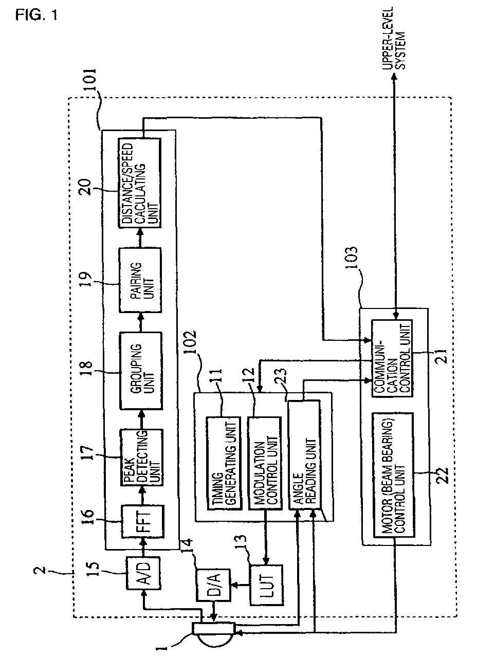
- Fig. 1 is a block diagram showing the structure of a radar system.
- a front end 1 transmits and receives milliwave signals
- a radar controller 2 is connected to the front end 1.
- a portion 101 is a signal processing unit for a beat signal
- a portion 102 is a control unit that modulates a transmitting signal and detects a beam bearing
- a portion 103 performs beam scanning and communication control.
- a timing generating unit 11 generates a timing signal for modulating a transmitting signal.
- a modulation control unit 12 outputs, to a look-up table (LUT) 13, control data (values) for transmitting a milliwave signal at the transmitting frequency required at each temporal point.
- LUT look-up table
- a digital-to-analog (D/A) converter 14 supplies the front end 1 with an analog voltage signal in accordance with a value output from the LUT 13.
- the front end 1 includes a voltage-controlled oscillator (VCO).
- VCO voltage-controlled oscillator
- the front end 1 is supplied as an input control voltage for the VCO with a voltage output from the D/A converter 14, and transmits a milliwave signal having a frequency in accordance with the voltage.
- the front end 1 includes a mixing circuit that outputs a beat signal generated by mixing a local signal extracted by performing coupling on the transmitting signal with a reception signal.
- An analog-to-digital (A/D) converter 15 samples the beam signal for each predetermined sampling period and converts the beat signal into digital data strings or data rows.
- the signal processing unit 101 includes a digital signal processor (DSP), and the signal processing in the signal processing unit 101 is mainly summation calculation and is performed by program processing.
- DSP digital signal processor
- An FFT (Fast Fourier Transformation) processor 16 finds a signal-intensity-representing frequency spectrum for each of the discrete frequencies by performing high-speed Fourier transformation on a number of input portions of predetermined sampling data. For example, a power spectrum is determined.
- a peak detecting unit 17 detects the peak frequency of a peak in a signal intensity appearing in the frequency spectrum and the signal intensity of the peak frequency.
- a grouping unit 18 extracts, as a peak group, a group of peaks appearing in the frequency spectrum and lining up within a predetermined frequency difference consecutively in beam bearings.
- a pairing unit 19 checks pairs of a plurality of peak groups in an up-modulating interval and a plurality of peak groups in a down-modulating interval, and determines a combination of peak groups caused by a single target.
- a distance/speed calculating unit 20 calculates, for the paired groups of peak groups, a relative distance to the target causing the peak groups and its speed based on a peak frequency in the up-modulating interval and a peak frequency in the down-modulating interval.
- a motor (beam bearing) control unit 22 supplies the front end 1 with beam-bearing control data.
- the front end 1 includes a motor for changing a beam bearing, and directs a beam in a bearing designated based on the control data from the motor (beam bearing) control unit 22. Also, the front end 1 includes a unit for outputting a signal for detecting the beam bearing, and an angle reading unit 23 determines the present beam bearing by reading the signal.
- a communication control unit 21 outputs, to an upper-level system (host apparatus), data of a relative distance to each target and its relative speed in the beam bearing.
- the communication control unit 21 receives control data from the upper-level system and supplies the data to a modulation/beam-bearing detecting unit 102. For example, the setting of a changing speed of the beam bearing, the speed of repeating the up-modulating interval and the down-modulating interval, and other processes, are performed.
- the upper-level system includes a unit for measuring the movement speed of a movable object provided with this radar system.
- the communication control unit 21 reads information concerning the movement speed.
- Fig. 2 shows an example of a shift, caused by the distance to a target and its relative speed, of a frequency change in a transmitting signal and a reception signal.
- a frequency difference between the transmitting signal and the reception signal in a frequency rising mode of the transmitting signal is an upbeat frequency f BU
- a frequency difference between the transmitting signal and the reception signal in a frequency dropping mode of the transmitting signal is a downbeat frequency f BD .
- a shift (time difference) in time domain between the transmitting signal and the reception signal corresponds to round-trip time of electromagnetic waves from an antenna to the target.
- a shift in frequency between the transmitting signal and the reception signal is a Doppler shift, and this is caused by the relative speed of the target to the antenna.
- the time difference and the Doppler shift change the values of the upbeat f BU and the downbeat f BD .
- the frequencies of the upbeat and the downbeat are calculated.
- Fig. 3 shows an example of the relationship between the bearings of the radar system's transmitting and received beams and a plurality of targets, where Bo denotes the front direction of the radar system when it is installed on a vehicle.
- B+1, B+2,... denote beam bearings obtained when the beam bearing is changed from the front to the right.
- B-1, B-2,... denote beam bearings obtained when the beam bearing is changed from the front to the left.
- the circle targets OB2 and OB5 indicate fixed roadside objects. Also, the rectangular targets OB1, OB3, and OB4 indicate other vehicles existing ahead of the vehicle. The arrows indicate the traveling directions of the targets.
- Fig. 4 is a rectangular coordinates illustration showing peak frequencies in the peaks of up-modulating intervals of different directional beams, where the horizontal axis indicates beam bearings, and the vertical axis indicates the peak frequencies in the peaks included in the frequency spectrum.
- peak groups G1 to G5 having consecutive peak frequencies are caused by targets OB1 to OB5 shown in Fig. 3.
- peak frequencies in the peaks in the frequency spectrum line up in the beam bearings. For example, the positions of peaks in the frequency spectrum which are caused by the target OB1 traveling ahead of the vehicle at a speed that is lower than that of the vehicle consecutively appear within a predetermined frequency difference in six beams B-4 to B+1.
- the peak frequencies caused by the object OB2 as a roadside object appear in four beams B-5 to B-2.
- the peak frequencies are grouped as each peak group.
- a signal having a beam width of about 3.0 degrees is emitted in units of about 0.5 degrees
- seven adjacent beams have peak frequencies caused by one target.
- the peak frequencies By treating the peak frequencies as a peak group (hereinafter referred to simply as a "group"), an increase in pairing precision is achieved.
- the amount of data to be treated can be reduced.
- the central bearing of consecutive bearings spread in beam bearings is treated as the typical bearing of the group
- the central frequency of peak frequencies is treated as the typical frequency of the group
- the average or maximum of signal intensity is treated as the typical signal intensity of the group.
- a frequency range to be used for grouping of peak frequencies on adjacent beams may be frequencies corresponding to a distance in which a target can move in a scanning time (the time taken for scanning from one beam to an adjacent beam) for one beam.
- a scanning time the time taken for scanning from one beam to an adjacent beam
- discrete frequencies are used, only a frequency range corresponding to one FFT range bin can be widely set. This enables grouping to be adapted for a relative distance change in beam scanning of the object.
- the frequency spectrum data is unnecessary. Also, after performing grouping, the typical bearing and typical signal intensity of the group are only used in pairing. Thus, after the grouping, data of peak frequencies and signal intensities for beams are also unnecessary. This eliminates the need for a large memory capacity, and can reduce a data processing amount.
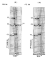
- Figs. 5A and 5B show treatment of apparent peak groups generated by effects of noise.
- groups denoted by G1 to G3 and N1 are detected, and in the group denoted by N1, only two beams have peak frequencies.
- reception signals reflected by one target should form a group spread in directions corresponding to angles for beam widths, even if the beam-bearing width is narrow. Therefore, a group bearing width that is narrower than the range is regarded as a group bearing width that is not formed by reflection off of an actual target.
- the group N1 shown in Fig. 5A is treated as an apparently specific group generated by noise.
- the groups G1, G2, and G3 are used for pairing which is described later.
- the width in bearing of a beam which is detected by the side lobe of the antenna is half as large as the width in bearing of the beam which is detected by the main lobe. Accordingly, when reflected waves from the target are received, a group which has a smaller number of beams in the beam bearings is formed, such as the group N1 shown in Fig. 5A. By excluding the influence of the side lobe, target-bearing misdetection is prevented from occurring and an increase in pairing precision is achieved.
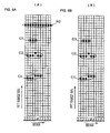
- Figs. 6A and 6B are illustrations of treatment of other noise components.
- a group having such long consecutive peaks in beam bearings are not found in the case of an actual target is regarded as a specific group and is excluded.
- a signal component in which, if a factor of a difference in signal intensity which is caused by antenna characteristics or other factors, is eliminated, peaks appear at almost identical signal intensities in all the bearings of a search range can be regarded as a constantly existing noise component.
- a group having consecutive peaks in all bearings is formed. Accordingly, in order that this may not be regarded as a specific group, when peaks at identical frequencies and identical signal intensities are observed in both the up-modulating interval and the down-modulating interval, it may be determined that the peaks form a specific group. Also, a pair of an up-modulating interval and a down-modulating interval is used as a frame, and this is repeatedly performed for a plurality of frames for modulation on a transmitting signal. When peaks at identical frequencies and identical signal intensities are observed in consecutive frames, it may be determined that the peaks form a specific group.
- the peaks may be regarded as a specific group and may be excluded.
- Pairing is performed to determine a combination of peak groups which are caused by a single target and which appear in an up-modulating interval and a down-modulating interval.
- the combination is determined by using features of the peak groups caused by the single target.
- Figs. 7A and 7B show pairing of groups having equal central bearings.
- Fig. 7A shows peak groups in the up-modulating interval
- Fig. 7B shows peak groups in the down-modulating interval.
- two groups having almost equal typical bearings are paired. For example, from the typical frequency of a group Gu1 in the up-modulating interval and the central frequency of a group Gd1 in the down-modulating interval, a relative distance and relative speed with respect to a target forming the groups are calculated. This similarly applies to the other groups.
- Figs. 8A and 8B show an example of pairing by using a feature in which the signal intensities of groups caused by a single target are almost equal between the up-modulating interval and the down-modulating interval.
- there are groups Gu1 and Gu2 in almost identical bearings in the up-modulating interval while there are groups Gd1 and Gd2 in almost identical bearings in the down-modulating interval.
- the groups Gu1 and Gd1 are paired and the groups Gu2 and Gd2 are paired.
- Fig. 8C shows the signal intensities of two groups in the up-modulating interval
- Fig. 8D shows the signal intensities of two groups in the down-modulating interval.
- the horizontal axis indicates a frequency
- the vertical axis indicates signal intensity.
- Figs. 9A and 9B show an example of pairing of those in which the results of calculating relative speeds are within a possible target-relative-speed range.
- the difference between the frequency of a group detected in the up-modulating interval and the frequency of a group detected in the down-modulating interval is proportional to the relative speed of the target. For example, when the traveling speed of the vehicle is about 100 km/h, and the absolute speed of the target is about 200 km/h or less, the relative speed of a target is about - 100 km/h to about +300 km/h. In other words, when the target travels at about 200 km/h ahead of the vehicle in its direction, the relative speed is about -100 km/h.
- the relative speed is about +300 km/h. Accordingly, those in which the difference in frequency between the up-modulating interval and the down-modulating interval is within the above-described range are paired.
- the groups Gu1 and Gd1 are paired, and the groups Gu2 and Gd2 are paired.
- Figs. 10A and 10B show an example of pairing based on the similarities of signal-intensity profiles in the beam bearings of peak groups.
- a change in the signal-reflected position of the target is determined based on the shape and material of a reflection surface of the target.
- a change in signal intensity in the beam bearing is similar in the up-modulating interval and the down-modulating interval.
- Figs. 10A and 10B show examples of the signal intensity profiles in beam bearings of two groups in the up-modulating interval and the down-modulating interval. Since groups Gu1 and Gd1 are similar to each other in signal intensity profile, this set is used as a pair. Similarly, since groups Gu2 and Gd2 are similar to each other in signal intensity profile, this set is used as a pair.
- a relative coefficient between the signal intensity profiles is calculated, and those in which in the value is larger are paired at higher priority.
- a process of the radar controller 2 shown in Fig. 1 which includes the above grouping and pairing is shown in a flowchart in Fig. 11.
- the motor (beam bearing) control unit 22 controls the beam to be directed to an initial bearing (n1).
- portions of beat-signal digital data generated by conversion by the A/D converter 15 are obtained as many as a predetermined number of times that sampling is performed, and are FFT-processed (n2 ⁇ n3).
- peak detection is performed (n4). Specifically, a portion at which the signal intensity of the frequency spectrum peaks in a pointed form is detected, and the peak frequency and signal intensity at the peak frequency are extracted.
- a peak frequency spectrum for each beam bearing in the up-modulating interval and the down-modulating interval is determined.
- the signal intensity of each group is extracted (n8).
- a signal intensity at the peak frequency in the center of beam bearings is used as a typical signal intensity of the group.
Landscapes
- Engineering & Computer Science (AREA)
- Radar, Positioning & Navigation (AREA)
- Remote Sensing (AREA)
- Physics & Mathematics (AREA)
- Computer Networks & Wireless Communication (AREA)
- General Physics & Mathematics (AREA)
- Electromagnetism (AREA)
- Signal Processing (AREA)
- Radar Systems Or Details Thereof (AREA)
- Traffic Control Systems (AREA)
Abstract
Description
Claims (9)
- A radar system (2) comprising:characterized in that a peak group (N1) in which the peaks consecutively appear in all of the beam bearings and the signal intensity of the peaks is substantially constant are regarded as a specific group, and the checking is performed excluding the specific group.a transmitting/receiving unit (1) for transmitting a transmitting signal changing in a triangular waveform so that a frequency-gradually-rising up-modulating interval and a frequency-gradually-dropping down-modulating interval are temporally repeated and for receiving a reception signal including a reflected signal from a target;a scanning unit (103) for changing the beam bearing of the transmitting signal for predetermined bearing angles;a frequency-analysing unit (16) for determining data on the frequency spectrum of a beat signal representing a frequency difference between the transmitting signal and the reception signal;a detection unit (20) for detecting, based on the frequency of the beat signal in the up-modulating interval and the frequency of the beat signal in the down-modulating interval, at least one of a relative distance to the target and a relative speed thereof; anda checking unit (19) in which, peak groups (G1, G2, G3, G4, G5) each including consecutive peaks appearing in the frequency spectrum in the beam bearings within a predetermined frequency difference are regarded as being caused by waves reflected by a single target (OB1-OB5), and said checking unit (19) performs checking, in pairs, of each peak group (G1-G5) in the up-modulating interval and each peak group (G1-G5) in the down-modulating interval;
- A radar system according to claim 1, wherein, when the specific group appears in both of the up-modulating interval and the down-modulating interval, the specific group is excluded.
- A radar according to claim 1, wherein, when the specific group repeatedly appears in accordance with the repetition of both modulating intervals, the specific group is excluded.
- A radar system according to claim 1, wherein said scanning unit (103) is arranged to change the speed of changing the beam bearing, and when the frequency of the specific group is substantially constant despite a change in the speed of changing the beam bearing, the specific group is excluded.
- A radar system (2) according to claim 1, wherein said transmitting/receiving unit (1) is arranged to change the speed of repeating the up-modulating interval and the down-modulating interval, and when the frequency of the specific group is substantially constant despite a change in the speed of repeating the up-modulating interval and the down-modulating interval, the specific group is excluded.
- A radar system (2) according to claim 1, wherein, among the peak groups (G1-G5), the checking unit (19) performs checking on two peak groups (G1-G5) having substantially equal central bearings.
- A radar system (2) according to claim 1, wherein, among the peak groups (G1-G5), the checking is performed on two peak groups (G1-G5), having substantially equal signal intensities.
- A radar system (2) according to claim 1, wherein said radar system is installed in a movable object and includes a unit (21) for capturing information on the movement speed of the movable object, and
a possible frequency range generated by combining the peak in the up-modulating interval and the peak in the down-modulating interval is set based on the movement speed, and the checking is performed for the frequency range. - A radar system (2) according to claim 1, wherein correlations between the signal-intensity profiles in the bearings of the peak groups (G1-G5) are determined, and the checking is performed so that higher priority is given to a peak group (G1-G5) having a higher correlation.
Applications Claiming Priority (3)
| Application Number | Priority Date | Filing Date | Title |
|---|---|---|---|
| JP2001380593A JP3729127B2 (en) | 2001-12-13 | 2001-12-13 | Radar |
| JP2001380593 | 2001-12-13 | ||
| EP02027631A EP1319961B1 (en) | 2001-12-13 | 2002-12-11 | FM-CW radar system |
Related Parent Applications (1)
| Application Number | Title | Priority Date | Filing Date |
|---|---|---|---|
| EP02027631A Division EP1319961B1 (en) | 2001-12-13 | 2002-12-11 | FM-CW radar system |
Publications (3)
| Publication Number | Publication Date |
|---|---|
| EP1477826A2 true EP1477826A2 (en) | 2004-11-17 |
| EP1477826A3 EP1477826A3 (en) | 2004-12-01 |
| EP1477826B1 EP1477826B1 (en) | 2006-01-11 |
Family
ID=19187204
Family Applications (2)
| Application Number | Title | Priority Date | Filing Date |
|---|---|---|---|
| EP02027631A Expired - Lifetime EP1319961B1 (en) | 2001-12-13 | 2002-12-11 | FM-CW radar system |
| EP04012776A Expired - Lifetime EP1477826B1 (en) | 2001-12-13 | 2002-12-11 | FM-CW radar system |
Family Applications Before (1)
| Application Number | Title | Priority Date | Filing Date |
|---|---|---|---|
| EP02027631A Expired - Lifetime EP1319961B1 (en) | 2001-12-13 | 2002-12-11 | FM-CW radar system |
Country Status (6)
| Country | Link |
|---|---|
| US (1) | US6753805B2 (en) |
| EP (2) | EP1319961B1 (en) |
| JP (1) | JP3729127B2 (en) |
| KR (1) | KR100645771B1 (en) |
| CN (2) | CN100340866C (en) |
| DE (2) | DE60202990T2 (en) |
Cited By (1)
| Publication number | Priority date | Publication date | Assignee | Title |
|---|---|---|---|---|
| EP2273283A4 (en) * | 2008-05-09 | 2011-05-18 | Honda Motor Co Ltd | Object detecting apparatus |
Families Citing this family (57)
| Publication number | Priority date | Publication date | Assignee | Title |
|---|---|---|---|---|
| EP1310804B1 (en) * | 2001-11-08 | 2010-12-22 | Fujitsu Ten Limited | Scan type radar device |
| JP3753071B2 (en) | 2002-01-07 | 2006-03-08 | 株式会社村田製作所 | Radar |
| JP3797277B2 (en) * | 2002-06-04 | 2006-07-12 | 株式会社村田製作所 | Radar |
| US6906661B2 (en) * | 2002-10-17 | 2005-06-14 | Honda Motor Co., Ltd. | Object-detecting system for vehicle |
| JP3736521B2 (en) * | 2002-12-19 | 2006-01-18 | 株式会社デンソー | Vehicle object recognition device |
| US7136753B2 (en) | 2002-12-05 | 2006-11-14 | Denso Corporation | Object recognition apparatus for vehicle, inter-vehicle control apparatus, and distance measurement apparatus |
| DE112004002165T5 (en) * | 2003-11-18 | 2006-09-07 | Murata Mfg. Co., Ltd., Nagaokakyo | radar system |
| US7312745B2 (en) * | 2004-01-07 | 2007-12-25 | Murata Manufacturing Co., Ltd | Radar |
| JP2006151125A (en) * | 2004-11-26 | 2006-06-15 | Omron Corp | In-vehicle image processing device |
| JP4697072B2 (en) * | 2006-07-04 | 2011-06-08 | 株式会社デンソー | Radar equipment |
| JP2008082956A (en) * | 2006-09-28 | 2008-04-10 | Mazda Motor Corp | Vehicle obstacle detection device and detection method thereof |
| JP4737165B2 (en) * | 2006-10-31 | 2011-07-27 | 株式会社村田製作所 | Radar target detection method and radar apparatus using the target detection method |
| JP2009042181A (en) * | 2007-08-10 | 2009-02-26 | Denso Corp | Estimator |
| US7612707B2 (en) * | 2007-09-28 | 2009-11-03 | Banner Engineering Corporation | Configurable radar sensor |
| DE102007061235A1 (en) * | 2007-12-19 | 2009-06-25 | Robert Bosch Gmbh | Method for classifying distance data and corresponding distance measuring device |
| KR100980670B1 (en) | 2008-04-02 | 2010-09-07 | 엘아이지넥스원 주식회사 | Representative azimuth calculation method and apparatus using the same |
| JP5407272B2 (en) * | 2008-06-12 | 2014-02-05 | 三菱電機株式会社 | Radar equipment |
| JP4843003B2 (en) * | 2008-08-05 | 2011-12-21 | 富士通テン株式会社 | Signal processing apparatus, radar apparatus, and signal processing method |
| JP5317570B2 (en) * | 2008-08-07 | 2013-10-16 | 富士通テン株式会社 | Radar apparatus and target detection method |
| GB2464914B (en) * | 2008-08-22 | 2012-07-25 | Trw Automotive Us Llc | Vehicle length sensors |
| JP5254104B2 (en) * | 2009-03-27 | 2013-08-07 | Kddi株式会社 | POSITION INFORMATION ACQUISITION DEVICE, POSITION INFORMATION ACQUISITION SYSTEM, POSITION INFORMATION ACQUISITION METHOD, AND PROGRAM |
| DE102009002243A1 (en) | 2009-04-07 | 2010-10-14 | Robert Bosch Gmbh | FMCW radar sensor and frequency matching method |
| KR101122523B1 (en) * | 2009-11-26 | 2012-03-16 | 재단법인대구경북과학기술원 | Method and apparatus for vehicle uwb radar signal processing distinguishing plural vehicle |
| TW201133412A (en) * | 2010-03-19 | 2011-10-01 | Cct Co Ltd | Method of using radar vehicle detector to determine vehicle type, speed, and radar detection zone width |
| JP5693906B2 (en) * | 2010-10-13 | 2015-04-01 | 三菱電機株式会社 | Radar equipment |
| JP5779370B2 (en) * | 2011-03-16 | 2015-09-16 | 日本電産エレシス株式会社 | Electronic scanning radar apparatus, received wave direction estimation method, and program |
| CN103477243B (en) * | 2011-03-24 | 2016-04-27 | 古河电气工业株式会社 | radar device |
| JP5278484B2 (en) | 2011-04-21 | 2013-09-04 | 株式会社デンソー | Radar equipment |
| JP2012242166A (en) * | 2011-05-17 | 2012-12-10 | Fujitsu Ten Ltd | Radar device |
| JP5382087B2 (en) * | 2011-11-02 | 2014-01-08 | 株式会社デンソー | Radar equipment |
| JP6004694B2 (en) | 2012-03-26 | 2016-10-12 | 富士通テン株式会社 | Radar apparatus and target detection method |
| JP5605395B2 (en) * | 2012-06-08 | 2014-10-15 | 株式会社デンソー | Vehicle determination device and program |
| JP6190140B2 (en) * | 2012-06-21 | 2017-08-30 | 古野電気株式会社 | Target detection apparatus and target detection method |
| JP6280319B2 (en) * | 2012-10-30 | 2018-02-14 | 株式会社デンソーテン | Radar apparatus and signal processing method |
| US9279883B2 (en) * | 2013-02-19 | 2016-03-08 | Infineon Technologies Ag | Method and device for radar applications |
| JP6265617B2 (en) * | 2013-03-29 | 2018-01-24 | 株式会社デンソーテン | Radar apparatus and signal processing method |
| JP2015155807A (en) * | 2014-02-20 | 2015-08-27 | 富士通テン株式会社 | Radar device, vehicle control system, and signal processing method |
| JP6331195B2 (en) * | 2014-09-29 | 2018-05-30 | パナソニックIpマネジメント株式会社 | Radar equipment |
| JP2018025475A (en) * | 2016-08-10 | 2018-02-15 | 株式会社デンソー | Radar transceiver |
| KR102443626B1 (en) | 2016-11-29 | 2022-09-14 | 블랙모어 센서스 앤드 애널리틱스, 엘엘씨 | Method and system for classification of objects in point cloud data sets |
| CN110114632B (en) | 2016-11-30 | 2021-10-29 | 布莱克莫尔传感器和分析有限责任公司 | Method and system for Doppler detection and Doppler correction for optical chirp range detection |
| WO2018125438A2 (en) | 2016-11-30 | 2018-07-05 | Blackmore Sensors and Analytics Inc. | Method and system for adaptive scanning with optical ranging systems |
| CN110140064B (en) | 2016-11-30 | 2023-07-18 | 布莱克莫尔传感器和分析有限责任公司 | Method and system for automatic real-time adaptive scanning using optical ranging system |
| US10422880B2 (en) | 2017-02-03 | 2019-09-24 | Blackmore Sensors and Analytics Inc. | Method and system for doppler detection and doppler correction of optical phase-encoded range detection |
| JP6711319B2 (en) * | 2017-06-19 | 2020-06-17 | 株式会社デンソー | Perimeter monitoring radar device |
| US10401495B2 (en) | 2017-07-10 | 2019-09-03 | Blackmore Sensors and Analytics Inc. | Method and system for time separated quadrature detection of doppler effects in optical range measurements |
| WO2019209727A1 (en) | 2018-04-23 | 2019-10-31 | Blackmore Sensors and Analytics Inc. | Method and system for controlling autonomous vehicle using coherent range doppler optical sensors |
| US11822010B2 (en) | 2019-01-04 | 2023-11-21 | Blackmore Sensors & Analytics, Llc | LIDAR system |
| CN113260873A (en) | 2019-01-04 | 2021-08-13 | 布莱克莫尔传感器和分析有限责任公司 | LIDAR device with rotatable polygonal deflector having refractive facets |
| CN111862631B (en) * | 2019-05-24 | 2022-07-29 | 北京骑胜科技有限公司 | Vehicle running detection method and device, electronic equipment and readable storage medium |
| US11480662B2 (en) * | 2020-02-12 | 2022-10-25 | Aptiv Technologies Limited | Fast-scanning frequency-modulated continuous wave (FMCW) lidar systems |
| DE112020006713B4 (en) * | 2020-04-16 | 2024-06-20 | Mitsubishi Electric Corporation | Radar signal processing device, radar signal processing method, radar device and in-vehicle device |
| US11313955B1 (en) | 2020-10-22 | 2022-04-26 | Aeva, Inc. | Techniques to associate peaks in multi-target scenarios in coherent lidar systems |
| JP7593143B2 (en) * | 2021-01-27 | 2024-12-03 | 沖電気工業株式会社 | Monitoring device, system and method |
| JP7583685B2 (en) * | 2021-07-28 | 2024-11-14 | 株式会社デンソー | Measurement system, measurement method, and measurement program |
| US12130363B2 (en) | 2022-02-03 | 2024-10-29 | Aurora Operations, Inc. | LIDAR system |
| US12571914B2 (en) | 2023-10-05 | 2026-03-10 | Aurora Operations, Inc. | Systems and methods of LIDAR sensor systems having amplifier protection circuits |
Family Cites Families (21)
| Publication number | Priority date | Publication date | Assignee | Title |
|---|---|---|---|---|
| JP3099598B2 (en) | 1993-08-31 | 2000-10-16 | トヨタ自動車株式会社 | Relative distance detection device |
| JP3102224B2 (en) | 1993-09-28 | 2000-10-23 | トヨタ自動車株式会社 | In-vehicle radar device |
| JP3104558B2 (en) | 1995-02-01 | 2000-10-30 | トヨタ自動車株式会社 | Automotive radar equipment |
| JP2930236B1 (en) | 1998-01-26 | 1999-08-03 | 本田技研工業株式会社 | Radar equipment |
| JPH11271430A (en) * | 1998-03-25 | 1999-10-08 | Toyota Central Res & Dev Lab Inc | Automotive radar equipment |
| JP3565713B2 (en) * | 1998-05-27 | 2004-09-15 | 富士通テン株式会社 | Signal processing device for FM-CW scan radar |
| JP3492199B2 (en) * | 1998-06-02 | 2004-02-03 | 富士通テン株式会社 | FM-CW radar signal processing device |
| JP3480486B2 (en) * | 1998-08-18 | 2003-12-22 | トヨタ自動車株式会社 | FM-CW radar device |
| DE19942665B4 (en) | 1998-09-07 | 2014-02-13 | Denso Corporation | FM CW radar apparatus for measuring the distance to a target and the relative velocity of the target |
| JP3512066B2 (en) * | 1998-12-10 | 2004-03-29 | トヨタ自動車株式会社 | Automotive radar equipment |
| JP4258941B2 (en) * | 1999-06-03 | 2009-04-30 | 株式会社デンソー | Radar equipment |
| JP3530081B2 (en) * | 1999-08-12 | 2004-05-24 | 本田技研工業株式会社 | Multi-beam FM radar device |
| JP4134462B2 (en) * | 1999-10-28 | 2008-08-20 | 株式会社デンソー | Radar device, adjustment method, adjustment system |
| JP2001242240A (en) * | 2000-02-28 | 2001-09-07 | Aisin Seiki Co Ltd | Obstacle detection method, radar device and on-vehicle radar device |
| JP3600499B2 (en) * | 2000-03-17 | 2004-12-15 | 三菱電機株式会社 | FM pulse Doppler radar device |
| JP3635228B2 (en) * | 2000-06-29 | 2005-04-06 | 富士通テン株式会社 | Scanning radar signal processing method |
| JP3871875B2 (en) * | 2000-11-06 | 2007-01-24 | 日本電気株式会社 | Target classification method and apparatus |
| EP1310804B1 (en) * | 2001-11-08 | 2010-12-22 | Fujitsu Ten Limited | Scan type radar device |
| JP3703756B2 (en) * | 2001-11-08 | 2005-10-05 | 富士通テン株式会社 | Radar equipment |
| JP3753652B2 (en) * | 2001-12-04 | 2006-03-08 | 富士通テン株式会社 | Mispairing judgment and signal processing method of FM-CW radar |
| JP3675758B2 (en) * | 2001-12-11 | 2005-07-27 | 富士通テン株式会社 | Data processing equipment for millimeter wave radar |
-
2001
- 2001-12-13 JP JP2001380593A patent/JP3729127B2/en not_active Expired - Fee Related
-
2002
- 2002-12-06 US US10/310,807 patent/US6753805B2/en not_active Expired - Fee Related
- 2002-12-11 EP EP02027631A patent/EP1319961B1/en not_active Expired - Lifetime
- 2002-12-11 DE DE60202990T patent/DE60202990T2/en not_active Expired - Lifetime
- 2002-12-11 DE DE60208726T patent/DE60208726T2/en not_active Expired - Lifetime
- 2002-12-11 EP EP04012776A patent/EP1477826B1/en not_active Expired - Lifetime
- 2002-12-11 KR KR1020020078754A patent/KR100645771B1/en not_active Expired - Fee Related
- 2002-12-12 CN CNB021559562A patent/CN100340866C/en not_active Expired - Fee Related
- 2002-12-12 CN CN200610138992XA patent/CN1932551B/en not_active Expired - Fee Related
Cited By (2)
| Publication number | Priority date | Publication date | Assignee | Title |
|---|---|---|---|---|
| EP2273283A4 (en) * | 2008-05-09 | 2011-05-18 | Honda Motor Co Ltd | Object detecting apparatus |
| US8232912B2 (en) | 2008-05-09 | 2012-07-31 | Honda Motor Co., Ltd. | Object detecting apparatus |
Also Published As
| Publication number | Publication date |
|---|---|
| DE60208726T2 (en) | 2006-07-13 |
| JP3729127B2 (en) | 2005-12-21 |
| KR100645771B1 (en) | 2006-11-13 |
| DE60208726D1 (en) | 2006-04-06 |
| US20030117312A1 (en) | 2003-06-26 |
| CN1932551B (en) | 2010-06-23 |
| CN100340866C (en) | 2007-10-03 |
| US6753805B2 (en) | 2004-06-22 |
| EP1319961B1 (en) | 2005-02-16 |
| CN1932551A (en) | 2007-03-21 |
| JP2003185738A (en) | 2003-07-03 |
| EP1319961A1 (en) | 2003-06-18 |
| EP1477826B1 (en) | 2006-01-11 |
| DE60202990D1 (en) | 2005-03-24 |
| DE60202990T2 (en) | 2006-04-13 |
| CN1450361A (en) | 2003-10-22 |
| EP1477826A3 (en) | 2004-12-01 |
| KR20030051274A (en) | 2003-06-25 |
Similar Documents
| Publication | Publication Date | Title |
|---|---|---|
| EP1319961B1 (en) | FM-CW radar system | |
| EP1326088B1 (en) | Radar system | |
| US20100271257A1 (en) | Radar apparatus | |
| US7460058B2 (en) | Radar | |
| US6249243B1 (en) | Radar apparatus for use on vehicle | |
| EP1239298B1 (en) | Method and radar for detecting distance to a target | |
| US4994809A (en) | Polystatic correlating radar | |
| US7466260B2 (en) | Radar apparatus | |
| US8125375B2 (en) | Radar | |
| JP5552212B2 (en) | Radar device | |
| US20120223855A1 (en) | Radar apparatus | |
| US7675457B2 (en) | Radar system | |
| JP2000081475A (en) | How the radar system works | |
| JP3012805B2 (en) | FM radar equipment | |
| JP7345703B2 (en) | radar equipment | |
| US7312745B2 (en) | Radar | |
| JP2004037380A (en) | Radar | |
| US6369748B1 (en) | Radar system mounted on vehicle | |
| JPH11271434A (en) | Phase monopulse radar device | |
| JP4390916B2 (en) | Scanning radar equipment | |
| JP2001033546A (en) | Detecting device and method | |
| JP2000241536A (en) | FM-CW radar device | |
| JPH11281729A (en) | Beam switching type radar device | |
| JP3530081B2 (en) | Multi-beam FM radar device | |
| JP2003121533A (en) | Radar |
Legal Events
| Date | Code | Title | Description |
|---|---|---|---|
| PUAI | Public reference made under article 153(3) epc to a published international application that has entered the european phase |
Free format text: ORIGINAL CODE: 0009012 |
|
| PUAL | Search report despatched |
Free format text: ORIGINAL CODE: 0009013 |
|
| 17P | Request for examination filed |
Effective date: 20040528 |
|
| AC | Divisional application: reference to earlier application |
Ref document number: 1319961 Country of ref document: EP Kind code of ref document: P |
|
| AK | Designated contracting states |
Kind code of ref document: A2 Designated state(s): DE FR GB |
|
| AK | Designated contracting states |
Kind code of ref document: A3 Designated state(s): DE FR GB |
|
| GRAP | Despatch of communication of intention to grant a patent |
Free format text: ORIGINAL CODE: EPIDOSNIGR1 |
|
| AKX | Designation fees paid |
Designated state(s): DE FR GB |
|
| GRAS | Grant fee paid |
Free format text: ORIGINAL CODE: EPIDOSNIGR3 |
|
| GRAA | (expected) grant |
Free format text: ORIGINAL CODE: 0009210 |
|
| AC | Divisional application: reference to earlier application |
Ref document number: 1319961 Country of ref document: EP Kind code of ref document: P |
|
| AK | Designated contracting states |
Kind code of ref document: B1 Designated state(s): DE FR GB |
|
| REF | Corresponds to: |
Ref document number: 60208726 Country of ref document: DE Date of ref document: 20060406 Kind code of ref document: P |
|
| ET | Fr: translation filed | ||
| PLBE | No opposition filed within time limit |
Free format text: ORIGINAL CODE: 0009261 |
|
| STAA | Information on the status of an ep patent application or granted ep patent |
Free format text: STATUS: NO OPPOSITION FILED WITHIN TIME LIMIT |
|
| 26N | No opposition filed |
Effective date: 20061012 |
|
| PGFP | Annual fee paid to national office [announced via postgrant information from national office to epo] |
Ref country code: DE Payment date: 20121205 Year of fee payment: 11 |
|
| PGFP | Annual fee paid to national office [announced via postgrant information from national office to epo] |
Ref country code: GB Payment date: 20121205 Year of fee payment: 11 |
|
| PGFP | Annual fee paid to national office [announced via postgrant information from national office to epo] |
Ref country code: FR Payment date: 20130107 Year of fee payment: 11 |
|
| REG | Reference to a national code |
Ref country code: DE Ref legal event code: R119 Ref document number: 60208726 Country of ref document: DE |
|
| GBPC | Gb: european patent ceased through non-payment of renewal fee |
Effective date: 20131211 |
|
| REG | Reference to a national code |
Ref country code: FR Ref legal event code: ST Effective date: 20140829 |
|
| REG | Reference to a national code |
Ref country code: DE Ref legal event code: R119 Ref document number: 60208726 Country of ref document: DE Effective date: 20140701 |
|
| PG25 | Lapsed in a contracting state [announced via postgrant information from national office to epo] |
Ref country code: DE Free format text: LAPSE BECAUSE OF NON-PAYMENT OF DUE FEES Effective date: 20140701 |
|
| PG25 | Lapsed in a contracting state [announced via postgrant information from national office to epo] |
Ref country code: FR Free format text: LAPSE BECAUSE OF NON-PAYMENT OF DUE FEES Effective date: 20131231 Ref country code: GB Free format text: LAPSE BECAUSE OF NON-PAYMENT OF DUE FEES Effective date: 20131211 |