JP5779370B2 - Electronic scanning radar apparatus, received wave direction estimation method, and program - Google Patents
Electronic scanning radar apparatus, received wave direction estimation method, and program Download PDFInfo
- Publication number
- JP5779370B2 JP5779370B2 JP2011058127A JP2011058127A JP5779370B2 JP 5779370 B2 JP5779370 B2 JP 5779370B2 JP 2011058127 A JP2011058127 A JP 2011058127A JP 2011058127 A JP2011058127 A JP 2011058127A JP 5779370 B2 JP5779370 B2 JP 5779370B2
- Authority
- JP
- Japan
- Prior art keywords
- frequency
- spectrum
- beat
- target
- order
- Prior art date
- Legal status (The legal status is an assumption and is not a legal conclusion. Google has not performed a legal analysis and makes no representation as to the accuracy of the status listed.)
- Expired - Fee Related
Links
Images

Landscapes
- Radar Systems Or Details Thereof (AREA)
Description
本発明は、放射された送信波に対するターゲットからの反射波を用いて、このターゲットの検出を行う、車載用に好適な電子走査型レーダ装置、受信波方向推定方法及びプログラムに関する。 The present invention relates to an electronic scanning radar apparatus suitable for in-vehicle use, a reception wave direction estimation method, and a program for detecting a target using a reflected wave from a target with respect to a radiated transmission wave.
従来、車載用の電子走査型レーダ装置において、ターゲット(反射物)からの到来波(或いは受信波)の方向を検出する技術としては、アレーアンテナの到来波方向推定方法が用いられている。
この到来波方向推定方法は、近年、少ないチャンネル(CH)数で高い分解能が得られるARスペクトル推定法や、MUSIC(MUltiple SIgnal Classification)法などの高分解能アルゴリズムを使用したスペクトル推定法が用いられている(特許文献1、2、3参照)。また、ARスペクトル推定法は、最大エントロピー法(MEM:Maximum Entropy Method )や線形予測法などといわれる場合もある。
特許文献1から3においては、DBF(ディジタル・ビーム・フォーミング)との組合せによる手法が示されており、特許文献2、3の一部の実施形態では、DBFを用いない手法についても示されている。例えば、特許文献2における第2実施形態、すなわちDBFを用いない手法では、FMCW方式における周波数変調の上り(上昇部分)と下り(下降部分)のピークの組合せについて、高分解能アルゴリズムによって検出された角度情報に基づいて組合せ処理が行われている。
Conventionally, in an in-vehicle electronic scanning radar apparatus, an arrival direction estimation method of an array antenna has been used as a technique for detecting the direction of an incoming wave (or a received wave) from a target (reflector).
In recent years, this arrival wave direction estimation method uses a spectrum estimation method using a high resolution algorithm such as an AR spectrum estimation method capable of obtaining a high resolution with a small number of channels (CH) and a MUSIC (MUltiple SIgnal Classification) method. (See
In
ARスペクトル推定法は、高分解能アルゴリズムの中でも格段に演算負荷の軽いアルゴリズムである。そのため、距離方向(FMCW方式におけるビート周波数方向)に存在する多数のターゲットに対しての方位検出処理をそれぞれ行うことができる。それゆえ、ARスペクトル推定法は、検知可能な全周波数ポイントや連続した特定の周波数ポイント区間を広く複数設ける場合など(例えば、特許文献3参照)の多ポイントのスペクトル推定(=多ポイント方位推定と定義する)に用いるのに好都合である。
しかしながら、ARスペクトル推定法を含む高分解能アルゴリズムにおいて、検出された信号のピークのレベルは、ターゲットからの到来波の信号強度に厳密に比例しない。
例えば、DBFを用いない手法では、FMCW方式における周波数変調の上り(上昇部分)と下り(下降部分)のピークの組合せについて、検出された信号のピークが示すレベル情報を使わずに、角度情報のみに基づいた組み合わせ処理が行われる(例えば、特許文献2における第2実施形態参照)。このように、角度情報のみに基づいた組み合わせ処理においては、十分な組合せ精度を確保することができず、さらなる組合せ精度の向上が求められている。
The AR spectrum estimation method is an algorithm with a remarkably light calculation load among high resolution algorithms. Therefore, it is possible to perform azimuth detection processing for a large number of targets existing in the distance direction (beat frequency direction in the FMCW method). Therefore, the AR spectrum estimation method is a multi-point spectrum estimation (= multi-point azimuth estimation and the like) in a case where a plurality of all detectable frequency points and a plurality of continuous specific frequency point sections are widely provided (for example, refer to Patent Document 3). It is convenient to use.
However, in a high resolution algorithm including an AR spectrum estimation method, the peak level of the detected signal is not strictly proportional to the signal strength of the incoming wave from the target.
For example, in the technique that does not use DBF, only the angle information is used without using the level information indicated by the peak of the detected signal for the combination of the peak of the frequency modulation in the FMCW system (upward part) and the peak of the downward part (downward part). (For example, refer to the second embodiment in Patent Document 2). Thus, in combination processing based only on angle information, sufficient combination accuracy cannot be ensured, and further improvement in combination accuracy is required.
本発明は、このような事情に鑑みてなされたもので、高分解能アルゴリズムを方位検出に応用した車載用レーダにおいて、多ポイント方位推定の上りと下りの組合せ精度を向上させる電子走査型レーダ装置、受信波方向推定方法及びプログラムを提供することを目的とする。 The present invention has been made in view of such circumstances, and in an in-vehicle radar in which a high-resolution algorithm is applied to azimuth detection, an electronic scanning radar device that improves the combination accuracy of uplink and downlink in multipoint azimuth estimation, It is an object of the present invention to provide a received wave direction estimation method and program.
(1)本発明は、移動体に搭載される電子走査型レーダ装置であり、送信された送信波を反射したターゲットから到来する受信波を受信する複数のアンテナを含んで構成される受信部と、前記送信波及び前記受信波からビート信号を生成するビート信号生成部と、前記ビート信号に基づいて前記ターゲットを検出する信号処理部と、を備え、前記信号処理部は、前記ビート信号を予め設定された周波数帯域幅を有するビート周波数に周波数分解して、前記ビート周波数毎に分解された前記ビート信号に基づいた複素数データを算出する周波数分解処理部と、前記複素数データに基づいて、次数を2次と定めた第1の方位スペクトルが算出され、同じ前記ビート周波数として示される周波数ポイントであって、前記第1の方位スペクトルを算出した周波数ポイントに対応する周波数ポイントにおいて、次数を1次と定めた第2の方位スペクトルが算出され、前記第1の方位スペクトルが算出された前記周波数ポイントに対応する複数のピーク間の相対角度と、前記第2の方位スペクトルのピークが示すピーク角度とから前記複数のピーク間の相対レベル差を算出するターゲット抽出部と、を備え、前記複数のピーク間の相対レベル差に基づいて、前記ターゲットを検出することを特徴とする。
(1) The present invention is an electronic scanning radar apparatus mounted on a moving body, and includes a receiving unit configured to include a plurality of antennas that receive a received wave arriving from a target that reflects a transmitted transmission wave. A beat signal generation unit that generates a beat signal from the transmission wave and the reception wave, and a signal processing unit that detects the target based on the beat signal, and the signal processing unit preliminarily outputs the beat signal. A frequency decomposition processing unit that performs frequency decomposition into beat frequencies having a set frequency bandwidth and calculates complex number data based on the beat signal decomposed for each beat frequency, and an order based on the complex number data first azimuth spectrum which defines the secondary is calculated, a frequency point indicated as the same said beat frequency, calculating said first orientation spectrum In the frequency points corresponding to the frequency point with a second orientation spectrum is calculated that defines the order primary and the relative angles between a plurality of peaks corresponding to the first said frequency point azimuth spectrum is calculated for A target extraction unit that calculates a relative level difference between the plurality of peaks from a peak angle indicated by a peak of the second azimuth spectrum, and based on the relative level difference between the plurality of peaks, the target Is detected.
(2)また、本発明は、上記発明において、前記信号処理部は、前記第1の方位スペクトルを算出する基となる前記複素数データを、複数の前記ビート周波数を含む周波数領域の範囲から抽出する周波数レベル検知部を備えることを特徴とする。 (2) Further, in the present invention according to the above invention, the signal processing unit extracts the complex data serving as a basis for calculating the first azimuth spectrum from a range of a frequency region including a plurality of beat frequencies. A frequency level detection unit is provided.
(3)また、本発明は、上記発明において、前記周波数レベル検知部は、前記複素数データを要素とする行列の固有値の大きさに基づいて、前記信号処理部におけるスペクトル推定処理に有効とされる前記複素数データであるか否かを判定することを特徴とする。 (3) Further, in the present invention according to the present invention, the frequency level detection unit is effective for spectrum estimation processing in the signal processing unit based on a size of an eigenvalue of a matrix having the complex data as an element. It is determined whether or not the data is complex number data.
(4)また、本発明は、上記発明において、前記複素数データに基づいて前記第1の方位スペクトルを算出する方位スペクトル算出部を備え、前記ターゲット抽出部は、前記算出された第1の方位スペクトルに基づいて前記複数のピークが存在すると判定した場合、前記第2の方位スペクトルを算出することを特徴とする。 (4) Moreover, this invention is provided with the azimuth | direction spectrum calculation part which calculates the said 1st azimuth spectrum based on the said complex number data in the said invention, The said target extraction part is the said calculated 1st azimuth spectrum. The second azimuth spectrum is calculated when it is determined that the plurality of peaks are present based on.
(5)また、本発明は、上記発明において、前記ターゲット抽出部は、前記複数のピーク間の角度の差と、前記複数のピーク間の相対レベル差との関係を示す相関式に従って、前記第2の方位スペクトルに基づいて算出されたピーク角度に基づいて前記相対レベル差を算出することを特徴とする。 (5) Further, in the present invention according to the above aspect, the target extraction unit may perform the first step according to a correlation equation indicating a relationship between an angle difference between the plurality of peaks and a relative level difference between the plurality of peaks. The relative level difference is calculated based on a peak angle calculated based on the azimuth spectrum of 2.
(6)また、本発明は、上記発明において、前記ターゲット抽出部は、前記送信波の周波数を順に上げる上り期間と、前記送信波の周波数を順に下げる下り期間のそれぞれの期間において検知された前記ピークを、対応する前記ターゲット毎にグループ化することを特徴とする。 (6) Moreover, the present invention is the above invention, wherein the target extraction unit is detected in each of an upstream period in which the frequency of the transmission wave is sequentially increased and a downstream period in which the frequency of the transmission wave is sequentially decreased. The peaks are grouped for each of the corresponding targets.
(7)また、本発明は、上記発明において、前記ターゲット抽出部は、前記検知されたピークを前記ターゲット毎にグループ化する処理を、該ターゲットに対する距離方向と角度方向とにおいて、予め定められる所定の距離と角度を基準とする領域を単位としてグループ化することを特徴とする。 (7) Also, in the present invention according to the above invention, the target extraction unit performs a process of grouping the detected peaks for each target in a predetermined distance direction and angle direction with respect to the target. An area based on the distance and angle is grouped in units.
(8)また、本発明は、上記発明において、前記複素数データから推定した次数に従って、前記第1の方位スペクトルと前記第2の方位スペクトルとを算出する方位スペクトル算出部を備えることを特徴とする。 (8) Further, the present invention is characterized in that, in the above-mentioned invention, an azimuth spectrum calculation unit that calculates the first azimuth spectrum and the second azimuth spectrum according to the order estimated from the complex data is provided. .
(9)また、本発明は、上記発明において、前記方位スペクトル算出部は、前記複素数データが要素である行列の固有値に基づいて前記次数を推定する次数推定部を備えることを特徴とする。 (9) Further, in the above invention, the present invention is characterized in that the azimuth spectrum calculation unit includes an order estimation unit that estimates the order based on an eigenvalue of a matrix in which the complex number data is an element.
(10)また、本発明は、上記発明において、前記方位スペクトル算出部は、前記複素数データに応じた次数に従った前記方位スペクトルの算出においては、自己回帰モデルを用いるARスペクトル推定法により行うことを特徴とする。 (10) Further, according to the present invention, in the above invention, the azimuth spectrum calculation unit performs the azimuth spectrum calculation according to the order corresponding to the complex data by an AR spectrum estimation method using an autoregressive model. It is characterized by.
(11)また、本発明は、上記発明において、前記方位スペクトル算出部は、前記周波数ポイントに対応させ、前記自己回帰モデルに基づいて生成された正規方程式の平均化処理を行ない、該平均化処理された正規方程式に基づいた前記ARスペクトル推定法による前記方位スペクトルを算出することを特徴とする (11) Further, in the present invention according to the above invention, the azimuth spectrum calculation unit performs an averaging process of a normal equation generated based on the autoregressive model, corresponding to the frequency point, and the averaging process Calculating the azimuth spectrum by the AR spectrum estimation method based on the normalized equation
(12)また、本発明は、移動体に搭載される電子走査型レーダ装置による受信波方向推定方法であり、受信部が、送信された送信波を反射したターゲットから到来する受信波を受信する複数のアンテナを含んで構成される受信過程と、ビート信号生成部が前記送信波及び前記受信波からビート信号を生成するビート信号生成過程と、周波数分解処理部が前記ビート信号を予め設定された周波数帯域幅を有するビート周波数に周波数分解して、前記ビート周波数毎に分解された前記ビート信号に基づいた複素数データを算出する周波数分解処理過程と、信号処理部が、前記ビート信号に基づいて前記ターゲットを検出する信号処理過程と、を含み、前記信号処理過程は、周波数分解処理部が、前記ビート信号を予め設定された周波数帯域幅を有するビート周波数に周波数分解して、前記ビート周波数毎に分解された前記ビート信号に基づいた複素数データを算出する周波数分解処理過程と、前記複素数データに基づいて、次数を2次と定めた第1の方位スペクトルが算出され、同じ前記ビート周波数として示される周波数ポイントであって、前記第1の方位スペクトルを算出した周波数ポイントに対応する周波数ポイントにおいて、次数を1次と定めた第2の方位スペクトルが算出され、前記ターゲット抽出部が、前記第1の方位スペクトルが算出された前記周波数ポイントに対応する複数のピーク間の相対角度と、前記第2の方位スペクトルのピークが示すピーク角度とから前記複数のピーク間の相対レベル差を算出するターゲット抽出過程と、前記複数のピーク間の相対レベル差に基づいて、前記ターゲットを検出する過程と、を含むことを特徴とする。 (12) Further, the present invention is a reception wave direction estimation method by an electronic scanning radar apparatus mounted on a moving body, and the reception unit receives a reception wave coming from a target reflecting the transmitted transmission wave. A reception process including a plurality of antennas, a beat signal generation process in which the beat signal generation unit generates a beat signal from the transmission wave and the reception wave, and a frequency resolution processing unit is preset with the beat signal A frequency decomposition process for calculating complex number data based on the beat signal decomposed for each beat frequency by performing frequency decomposition on a beat frequency having a frequency bandwidth, and a signal processing unit based on the beat signal A signal processing process for detecting a target, wherein the frequency resolution processing unit has a preset frequency bandwidth for the beat signal. And frequency resolution in the beat frequency, the beat frequency decomposition process of calculating the complex number data based on decomposed the beat signal for each frequency, based on the complex number data, first that defines the order secondary and A second azimuth spectrum in which the order is determined to be the first order at a frequency point corresponding to the frequency point at which the first azimuth spectrum is calculated. And the target extraction unit calculates the relative angle between a plurality of peaks corresponding to the frequency point at which the first azimuth spectrum is calculated and the peak angle indicated by the peak of the second azimuth spectrum. Target extraction process for calculating the relative level difference between multiple peaks and the relative level between the multiple peaks Based on, characterized in that it comprises a the steps of detecting said target.
(13)また、本発明は、移動体に搭載される電子走査型レーダ装置により受信波方向推定の動作をコンピュータに制御させるためのプログラムであり、送信された送信波を反射したターゲットから到来する受信波を受信する複数のアンテナを含んで構成される受信処理と、ビート信号生成部が前記送信波及び前記受信波からビート信号を生成するビート信号生成処理と、前記ビート信号を予め設定された周波数帯域幅を有するビート周波数に周波数分解して、前記ビート周波数毎に分解された前記ビート信号に基づいた複素数データを算出する周波数分解処理と、前記ビート信号に基づいて前記ターゲットを検出する信号処理と、を実行させ、前記信号処理は、前記ビート信号を予め設定された周波数帯域幅を有するビート周波数に周波数分解して、前記ビート周波数毎に分解された前記ビート信号に基づいた複素数データを算出する周波数分解処理と、前記複素数データに基づいて、次数を2次と定めた第1の方位スペクトルが算出され、同じ前記ビート周波数として示される周波数ポイントであって、前記第1の方位スペクトルを算出した周波数ポイントに対応する周波数ポイントにおいて、次数を1次と定めた第2の方位スペクトルが算出され、前記第1の方位スペクトルが算出された前記周波数ポイントに対応する複数のピーク間の相対角度と、前記第2の方位スペクトルのピークが示すピーク角度とから前記複数のピーク間の相対レベル差を算出するターゲット抽出処理と、を実行させ、前記複数のピーク間の相対レベル差に基づいて、前記ターゲットを検出するためのプログラムである。 (13) Further, the present invention is a program for causing a computer to control the operation of estimating the direction of a received wave by an electronic scanning radar apparatus mounted on a moving body, and arrives from a target reflecting a transmitted wave transmitted. A reception process including a plurality of antennas for receiving a reception wave, a beat signal generation process in which a beat signal generation unit generates a beat signal from the transmission wave and the reception wave, and the beat signal is preset. Frequency decomposition processing for calculating complex data based on the beat signal decomposed for each beat frequency by performing frequency decomposition into beat frequencies having a frequency bandwidth, and signal processing for detecting the target based on the beat signal And the signal processing is performed to frequency the beat signal to a beat frequency having a preset frequency bandwidth. Solution to a frequency decomposition process of calculating the complex number data based on the beat signals decomposed for each of the beat frequency, on the basis of the complex data, first orientation spectrum is calculated that defines the order secondary and A second azimuth spectrum having a degree of primary is calculated at a frequency point corresponding to the frequency point indicated as the beat frequency and corresponding to the frequency point at which the first azimuth spectrum is calculated; A target for calculating a relative level difference between the plurality of peaks from a relative angle between the plurality of peaks corresponding to the frequency point at which one azimuth spectrum is calculated and a peak angle indicated by a peak of the second azimuth spectrum. Extracting the target and detecting the target based on a relative level difference between the plurality of peaks. Is a program.
以上説明したように、本発明によれば、受信部が、送信された送信波を反射したターゲットから到来する受信波を受信する複数のアンテナを含んで構成される。ビート信号生成部が前記送信波及び前記受信波からビート信号を生成する。周波数分解処理部が前記ビート信号を予め設定された周波数帯域幅を有するビート周波数に周波数分解して、前記ビート周波数毎に分解された前記ビート信号に基づいた複素数データを算出する。
複素数データに基づいて、第1の方位スペクトルが算出され、同じ前記ビート周波数として示される周波数ポイントであって、第1の方位スペクトルを算出した周波数ポイントに対応する周波数ポイントにおいて、第1の方位スペクトルを算出する処理において定めた次数より低い次数に定めた第2の方位スペクトルが算出される。
ターゲット抽出部が、第1の方位スペクトルが算出された前記周波数ポイントに対応する複数のピーク間の相対角度と、前記第2の方位スペクトルのピークが示すピーク角度とから前記複数のピーク間の相対レベル差を算出する。
そして、電子走査型レーダ装置は、複数のピーク間の相対レベル差に基づいて、ターゲットを検出する。
これにより、相対レベル差を算出することにより、同一距離のマルチターゲットの相対レベル情報が付加できるので、上りと下りのピーク組合せにおいて、組合せの精度を向上できる等の高分解能アルゴリズムを用いる方位推定の信頼度を向上させることができる。
As described above, according to the present invention, the reception unit is configured to include a plurality of antennas that receive a reception wave that arrives from a target that reflects a transmitted transmission wave. A beat signal generation unit generates a beat signal from the transmission wave and the reception wave. A frequency resolving unit frequency-decomposes the beat signal into beat frequencies having a preset frequency bandwidth, and calculates complex number data based on the beat signal decomposed for each beat frequency.
Based on the complex data, the first azimuth spectrum is calculated, and the first azimuth spectrum is a frequency point indicated as the same beat frequency and corresponding to the frequency point at which the first azimuth spectrum is calculated. A second azimuth spectrum set to an order lower than the order set in the process of calculating is calculated.
The target extraction unit uses the relative angle between the plurality of peaks corresponding to the frequency point at which the first azimuth spectrum is calculated, and the peak angle indicated by the peak of the second azimuth spectrum. Calculate the level difference.
The electronic scanning radar apparatus detects the target based on the relative level difference between the plurality of peaks.
As a result, by calculating the relative level difference, it is possible to add the relative level information of multi-targets of the same distance. Reliability can be improved.
<ARスペクトル推定の説明>
以下、本発明の実施形態に適用するARスペクトル推定法について示す。
ARスペクトル推定法は、MUSIC法と同じくスペクトルを推定するスペクトル推定法として知られており、ARモデル(自己回帰モデル)を用いた推定処理を行う。
<Description of AR spectrum estimation>
The AR spectrum estimation method applied to the embodiment of the present invention will be described below.
The AR spectrum estimation method is known as a spectrum estimation method for estimating a spectrum, similar to the MUSIC method, and performs an estimation process using an AR model (autoregressive model).
ARスペクトル推定法は、まず線形式によって示されるARモデルを用いてモデル化して、入力データに基づいた正規方程式(自己相関行列や共分散行列と呼ばれる行列と、右辺ベクトルや相互相関ベクトルと呼ばれるベクトルも含まれる)を作成する。さらに、正規方程式に基づいて、ARフィルタの係数(AR係数)と入力白色雑音の分散値を求めた後、そのAR係数と入力白色雑音の分散値を用いてパワースペクトルを求め推定する手法である。入力データには、時系列のデータの他、本発明のレーダのような空間方向のチャネルデータでも適用できる。ARスペクトル推定法には、自己相関行列を用いた手法と共分散行列を用いた手法に大別され、自己相関行列を用いた手法として自己相関法(又は、ユールウォーカー法)とバーグ法があり、共分散行列を用いた方法として共分散法(Covariance Method)と改良共分散法(Modified Covariance Method)がある。また、改良共分散法は、前向き後向き線形予測法(FBLP Method;Forward and Backward Linear Prediction Method)とも呼ばれる。 The AR spectrum estimation method is first modeled using an AR model indicated by a linear form, and is based on a normal equation (a matrix called an autocorrelation matrix or a covariance matrix, a vector called a right-hand side vector or a cross-correlation vector) based on input data. Also included). Furthermore, after obtaining the AR filter coefficient (AR coefficient) and the variance value of the input white noise based on the normal equation, the power spectrum is obtained and estimated using the AR coefficient and the variance value of the input white noise. . As input data, in addition to time-series data, spatial channel data such as radar of the present invention can be applied. The AR spectrum estimation method is roughly classified into a method using an autocorrelation matrix and a method using a covariance matrix, and there are an autocorrelation method (or Yulewalker method) and a Berg method as methods using an autocorrelation matrix. As a method using a covariance matrix, there are a covariance method and a modified covariance method. The improved covariance method is also referred to as a forward and backward linear prediction method (FBLP Method).
(第1実施形態)
以下、本発明の実施形態による電子走査型レーダ装置(FMCW方式ミリ波レーダ)について図面を参照して説明する。
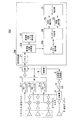
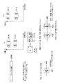
図1は、同実施形態における電子走査型レーダ装置の構成を示すブロック図である。
この図において、本実施形態による電子走査型レーダ装置100Aは、受信アンテナ1−1〜1−n、ミキサ2−1〜2−n、送信アンテナ3、分配器4、フィルタ5−1〜5―n、SW(スイッチ)6、ADC(A/Dコンバータ)7、制御部8、三角波生成部9、VCO10、信号処理部20Aを備える。
信号処理部20Aは、メモリ21、周波数分離処理部22A、周波数分解レベル検知部23A、ターゲット抽出部24、距離検出部25、速度検出部26、ターゲット確定部31、及び、方位スペクトル算出部30Aを備える。
(First embodiment)
Hereinafter, an electronic scanning radar apparatus (FMCW millimeter wave radar) according to an embodiment of the present invention will be described with reference to the drawings.
FIG. 1 is a block diagram showing the configuration of the electronic scanning radar apparatus according to the embodiment.
In this figure, the electronic scanning radar apparatus 100A according to the present embodiment includes receiving antennas 1-1 to 1-n, mixers 2-1 to 2-n, a transmitting antenna 3, a
The
次に、図1を参照して、本実施形態による電子走査型レーダ装置の動作を説明する。
受信アンテナ1−1〜1−nは、送信波がターゲットにて反射し、このターゲットから到来する反射波、すなわち受信波を受信する。
ミキサ2−1〜2−nは、送信アンテナ3から送信される送信波と、受信アンテナ1−1〜1−nそれぞれにおいて受信された受信波が増幅器により増幅された信号とを混合して、それぞれの周波数差に対応したビート信号を生成する。
送信アンテナ3は、三角波生成部9において生成された三角波信号を、VCO(Voltage Controlled Oscillator )10において周波数変調した送信信号をターゲットに対して送信波として送信する。
分配器4は、VCO10からの周波数変調された送信信号を、ミキサ2−1〜2−n及び送信アンテナ3に分配する。
Next, the operation of the electronic scanning radar apparatus according to the present embodiment will be described with reference to FIG.
The receiving antennas 1-1 to 1-n receive a reflected wave, i.e., a received wave, which is transmitted from the target, with the transmitted wave reflected by the target.
The mixers 2-1 to 2-n mix the transmission waves transmitted from the transmission antenna 3 and the signals obtained by amplifying the reception waves received at the reception antennas 1-1 to 1-n by the amplifiers. A beat signal corresponding to each frequency difference is generated.
The transmission antenna 3 transmits a transmission signal obtained by frequency-modulating the triangular wave signal generated by the triangular
The
フィルタ5−1〜5−n各々は、それぞれミキサ2−1〜2−nにおいて生成された各受信アンテナ1−1〜1−nに対応したCh1〜Chnのビート信号に対して帯域制限を行い、SW(スイッチ)6へ帯域制限されたビート信号を出力する。
SW6は、制御部8から入力されるサンプリング信号に対応して、フィルタ5−1〜5−n各々を通過した各受信アンテナ1−1〜1−nに対応したCh1〜Chnのビート信号を、順次切り替えて、ADC(A/Dコンバータ)7に出力する。
ADC7は、SW6から上記サンプリング信号に同期して入力される、各受信アンテナ1−1〜1−n各々に対応したCh1〜Chnのビート信号を、上記サンプリング信号に同期してA/D変換してデジタル信号に変換し、信号処理部20におけるメモリ21の波形記憶領域に順次記憶させる。
制御部8は、マイクロコンピュータなどにより構成されており、図示しないROMなどに格納された制御プログラムに基づき、図1に示す電子走査型レーダ装置全体の制御を行う。
Each of the filters 5-1 to 5-n performs band limitation on the beat signals of Ch1 to Chn corresponding to the reception antennas 1-1 to 1-n generated in the mixers 2-1 to 2-n, respectively. , A beat signal whose band is limited is output to SW (switch) 6.
SW6 corresponds to the sampling signal input from the
The
The
<距離、相対速度、角度(方位)を検出する原理>
次に、図を参照し、本実施形態における信号処理部20Aにおいて用いられる電子走査型レーダ装置とターゲットとの距離、相対速度、角度(方位)を検出する原理について簡単に説明する。
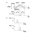
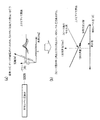
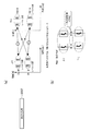
図2は、送信信号と、ターゲットに反射された受信信号が入力された状態を示す図である。
この図に示される信号は、図1の三角波生成部9において生成された信号をVCO10において周波数変調した送信信号と、その送信信号をターゲットが反射して、受信された受信信号である。この図の例では、ターゲットが1つの場合を示す。
図2(a)から判るように、送信する信号に対し、ターゲットからの反射波である受信信号が、ターゲットとの距離に比例して右方向(時間遅れ方向)に遅延されて受信される。さらに、ターゲットとの相対速度に比例して、送信信号に対して上下方向(周波数方向)に変動する。そして、図2(a)にて求められたビート信号の周波数変換(フーリエ変換やDTC、アダマール変換、ウェーブレッド変換など)後において、図2(b)に示されるように、ターゲットが1つの場合、上昇領域及び下降領域それぞれに1つのピーク値を有することなる。ここで、図2(a)は横軸が周波数、縦軸が強度を示す。
<Principle to detect distance, relative speed, angle (azimuth)>
Next, the principle of detecting the distance, relative speed, and angle (azimuth) between the electronic scanning radar apparatus used in the
FIG. 2 is a diagram illustrating a state in which a transmission signal and a reception signal reflected by a target are input.
The signal shown in this figure is a transmission signal obtained by frequency-modulating the signal generated in the triangular
As can be seen from FIG. 2A, a reception signal that is a reflected wave from the target is received with a delay in the right direction (time delay direction) in proportion to the distance from the target with respect to the signal to be transmitted. Furthermore, it varies in the vertical direction (frequency direction) with respect to the transmission signal in proportion to the relative speed with the target. Then, after the frequency conversion (Fourier transform, DTC, Hadamard transform, wave red transform, etc.) of the beat signal obtained in FIG. 2A, as shown in FIG. Each of the ascending region and the descending region has one peak value. Here, in FIG. 2A, the horizontal axis represents frequency and the vertical axis represents intensity.
周波数分解処理部22Aは、メモリ21に蓄積されたビート信号のサンプリングされたデータから、三角波の上昇部分(上り)と下降部分(下り)のそれぞれについて周波数分解、例えばフーリエ変換などにより離散時間に周波数変換する。すなわち、周波数分解処理部22Aは、ビート信号を予め設定された周波数帯域幅を有するビート周波数に周波数分解する。そして、周波数分解処理部22Aは、ビート周波数毎に分解されたビート信号に基づいた複素数データを算出する。
The
その結果、図2(b)に示すように、上昇部分と下降部分とにおいて、それぞれの周波数分解されたビート周波数毎の信号レベルのグラフが得られる。 As a result, as shown in FIG. 2B, a graph of the signal level for each beat frequency obtained by frequency decomposition is obtained in the rising portion and the falling portion.
次に、距離検出部25は、ターゲット抽出部24から入力される上昇部分のターゲット周波数fuと、下降部分のターゲット周波数fdとから、下記式により距離rを算出する。式中の「・」は乗算を示し、「/」は除算を示す。
r={C・T/(2・Δf)}・{(fu+fd)/2}
また、速度検出部26は、ターゲット抽出部24から入力される上昇部分のターゲット周波数fuと、下降部分のターゲット周波数fdとから、下記式により相対速度vを算出する。
v={C/(2・f0)}・{(fu−fd)/2}
上記距離r及び相対速度vを算出する式において、
C :光速度
Δf:三角波の周波数変調幅
f0 :三角波の中心周波数
T :変調時間(上昇部分/下降部分)
fu :上昇部分におけるターゲット周波数
fd :下降部分におけるターゲット周波数
Next, the
r = {C · T / (2 · Δf)} · {(fu + fd) / 2}
Further, the
v = {C / (2.f0)}. {(fu-fd) / 2}
In the formula for calculating the distance r and the relative velocity v,
C: speed of light Δf: frequency modulation width of triangular wave f0 : Triangular wave center frequency T: Modulation time (rising part / falling part)
fu : Target frequency in the rising part fd : Target frequency in the descending part
次に、本実施形態における受信アンテナ1−1〜1−nについて示す。
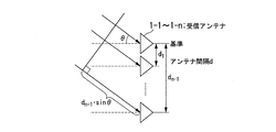
図3は、受信アンテナにおける受信波の説明を行う概念図である。
この図に示されるように、受信アンテナ1−1〜1−nは、間隔dによりアレー状に配置される。受信アンテナ1−1〜1−nには、アンテナを配列している面に対する垂直方向の軸に対して角度θ方向から入射される、ターゲットからの到来波(入射波、すなわち送信アンテナ3から送信した送信波に対するターゲットからの反射波)が入力する。このとき、その到来波は、受信アンテナ1−1〜1−nにおいて同一角度にて受信される。この同一角度、例えば角度θ及び各アンテナの間隔dにより求められる位相差「dn−1・sinθ」が、各隣接する受信アンテナ間にて発生する。
その位相差を利用して、アンテナ毎に時間方向に周波数分解処理された値を、高分解能アルゴリズム等の信号処理にて上記角度θを検出することができる。
Next, the receiving antennas 1-1 to 1-n in the present embodiment will be described.
FIG. 3 is a conceptual diagram illustrating the received wave at the receiving antenna.
As shown in this figure, the receiving antennas 1-1 to 1-n are arranged in an array at intervals d. The receiving antennas 1-1 to 1-n are incident waves from the target (incident waves, that is, transmitted from the transmitting antenna 3) that are incident on the axis perpendicular to the plane on which the antennas are arranged. The reflected wave from the target with respect to the transmitted wave) is input. At this time, the incoming waves are received at the same angle by the receiving antennas 1-1 to 1-n. A phase difference “dn −1 · sin θ” obtained by the same angle, for example, the angle θ and the interval d between the antennas, is generated between the adjacent receiving antennas.
By utilizing the phase difference, the angle θ can be detected by signal processing such as a high resolution algorithm for a value subjected to frequency resolution processing in the time direction for each antenna.
<信号処理部20Aにおける受信波に対する信号処理>
次に、図1を参照し、信号処理部20Aの一態様について示す。
信号処理部20Aを以下に示すように構成する。
メモリ21は、ADC7により波形記憶領域に対して、受信信号がA/D変換された時系列データ(上昇部分及び下降部分)を、アンテナ1−1〜1−n毎に対応させて記憶している。
周波数分解処理部22Aは、例えばフーリエ変換などにより、各Ch1〜Chn(各アンテナ1−1〜1−n)に対応するビート信号それぞれを、予め設定された分解能に応じて周波数成分に変換することによりビート周波数を示す周波数ポイントと、そのビート周波数の複素数データを出力する。
ここで、アンテナ毎の複素数データには、上記角度θに依存した位相差があり、それぞれの複素数データの複素平面上における絶対値(受信強度あるいは振幅など)は等価である。
周波数分解処理部22Aは、上昇部分(上り)及び下降部分(下り)共、受信チャンネル(CH)のそれぞれで、フーリエ変換(FFT)等の周波数分解処理を行い、ビート周波数(ドップラーシフトを含めた距離に相当)ポイント毎に振幅(又は電力)レベルを算出する。
<Signal Processing for Received Wave in
Next, an aspect of the
The
The
The frequency
Here, the complex number data for each antenna has a phase difference depending on the angle θ, and the absolute values (reception intensity, amplitude, etc.) of each complex number data on the complex plane are equivalent.
The
周波数分解レベル検知部23は、受信チャンネル毎の複素数データを平均した周波数スペクトルにより、振幅レベルを検知する。周波数分解レベル検知部23は、上昇部分(上り)及び下降部分(下り)共、最大値(尖頭値)を示すピークの周辺に存在し、最大値より小さな極大値(準尖頭値)を示すピークを含む周辺ポイントも演算対象とすることにより、多くの周波数(距離)ポイントを検知する。周波数分解レベル検知部23は、設定した閾値に基づいて、全受信チャンネルを平均した周波数スペクトルの振幅レベルを判定し、判定して選択された受信チャンネル毎の複素数データを有効な情報として抽出する。検知したポイントの受信チャンネル毎のデータを、抽出された複素数データと呼ぶ。このような処理により、周波数分解レベル検知部23は、後段の方位スペクトル推定処理に不要な情報を除去することができる。周波数分解レベル検知部23は、上昇部分(上り)及び下降部分(下り)の処理をそれぞれ別々に独立して行う。
なお、周波数分解レベル検知部23は、複素数データを要素とする行列の固有値の大きさに基づいて、信号処理部20Aにおけるスペクトル推定処理に有効とされる複素数データであるか否かを判定し、複素数データを抽出してもよい。
The frequency
The frequency resolution
方位スペクトル算出部30Aは、上昇部分(上り)及び下降部分(下り)共、レベル検知範囲(つまり抽出された複素数データ)の方位スペクトルとしてARスペクトル(=パワースペクトル)を算出する。
また、方位スペクトル算出部30Aは、AR係数を算出する際に、同時に白色雑音の分散値も算出する。
なお、以下の説明においては、方位スペクトル算出部30Aは、2次の改良共分散法(=前向き後向き線形予測法)によるARスペクトル推定を実施するものとして説明するが、バーグ(Burg)法等の他のスペクトル推定法を利用することも可能である。
The azimuth spectrum calculation unit 30A calculates an AR spectrum (= power spectrum) as the azimuth spectrum of the level detection range (that is, the extracted complex data) for both the rising portion (up) and the falling portion (down).
In addition, the azimuth spectrum calculation unit 30A calculates the dispersion value of the white noise at the same time when calculating the AR coefficient.
In the following description, the azimuth spectrum calculation unit 30A will be described as performing the AR spectrum estimation by the second-order improved covariance method (= forward-backward linear prediction method). Other spectral estimation methods can be used.
ターゲット抽出部24は、上昇部分(上り)及び下降部分(下り)共、周波数ポイント毎にARスペクトルのピークを算出し、ポイント毎のピーク数と角度を検知するARピーク検知処理を行う。
さらに、ターゲット抽出部24は、上昇部分(上り)及び下降部分(下り)共、同一の周波数ポイントにおいて、複数のピークが検出されたポイントにつては再度1次の改良共分散法によるスペクトル推定処理を行う。
また、ターゲット抽出部24は、後段の組合せ処理を行い易くするため、ピークをグループ化するグループ化処理を行う。このグループ化処理は、ターゲット単位に行われる。グループ化処理では、それぞれのピークを対象とし、特定のピークを基準にして、所定の距離と角度とにより定められる一定領域内に、他のピークが入るか否かを判定して、グループ化する。全てのグループには、そのターゲットまでの平均距離、そのターゲットを見込む平均角度の情報を、グループ毎それぞれに持たせる。また、複数のグループの方には、さらに平均相対レベル差の情報を持たせる(図11参照)。
また、ターゲット抽出部24は、上記のように、上昇部分(上り)及び下降部分(下り)に分けてそれぞれ処理してきた結果に基づいて、上りと下りの検出結果としてグループ化されたピークのグループを、さらに組合せるグループの組合せ処理を行う。
The
Furthermore, the
Further, the
In addition, the
距離検出部25は、順次入力される上昇領域及び下降領域それぞれの組合せのビート周波数を加算した数値によりターゲットとの上記距離rを演算する。
また、速度検出部26は、順次入力される上昇領域及び下降領域それぞれの組合せのビート周波数の差分によりターゲットとの上記相対速度vを演算する。
The
Further, the
ターゲット確定部31は、距離r、相対速度v、周波数ポイントと、方位スペクトル算出部30Aによって算出されたターゲットの方位とを結びつける。
The
続いて、図1から図12を参照し、信号処理部20Aにおける受信波に対する信号処理について示す。
図4は、信号処理部20Aにおける処理の手順を示すフローチャートである。
この図4に示されるフローチャートは、第1手段、第2手段、第3手段を組合せた手順を示している。また、図5〜図12は、図4のフローチャートにおいて示される信号処理部20Aにおける処理をそれぞれ説明する図である。
Next, with reference to FIGS. 1 to 12, signal processing for the received wave in the
FIG. 4 is a flowchart showing a processing procedure in the
The flowchart shown in FIG. 4 shows a procedure in which the first means, the second means, and the third means are combined. 5 to 12 are diagrams for explaining processing in the
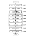
まず、ステップS001において、周波数分解処理部22Aは、メモリ21に蓄積されたビート信号のサンプリングされたデータから、三角波の上昇部分(上り)と下降部分(下り)とのそれぞれについて受信チャンネル毎に周波数分解処理を行う。そして、周波数分解処理部22Aは、ビート周波数に分解されたポイント毎の複素数データから、振幅(又は電力)レベル(周波数スペクトル)を算出する。
First, in step S001, the frequency
ステップS002において、周波数分解レベル検知部23は、受信チャンネル毎の複素数データを平均した周波数スペクトルにより、振幅レベルを検知する。周波数分解レベル検知部23は、上昇部分(上り)及び下降部分(下り)共、最大値(尖頭値)を示すピークの周辺に存在し、最大値より小さな極大値(準尖頭値)を示すピークを含む周辺のポイントも演算対象として、複数の周波数(距離)ポイントを検知する。
ここで、ステップS001とS002における処理を模式化した図5(a)を参照して説明する。図5(a)に示すように、チャンネルCH1からCHnまでのそれぞれのチャンネルにおいて、自装置からの距離に対するビート信号の振幅レベルをそれぞれグラフ化して示すことができる。特定の距離ポイントにターゲットがある場合、ビート信号の振幅レベルが大きくなる。例えば、連続した特定の周波数(距離)ポイントを抽出できるような、比較的低レベルの閾値Thfとして設定し、その閾値Thfに従って受信チャンネル(CH)の振幅レベルを判定する。
閾値Thfより大きな振幅レベルを示す距離ポイントにおいて、受信チャンネル毎の複素数データを抽出する。
In step S002, the frequency
Here, the process in steps S001 and S002 will be described with reference to FIG. As shown in FIG. 5 (a), the amplitude level of the beat signal with respect to the distance from the own apparatus can be graphed in each of the channels CH1 to CHn. When the target is at a specific distance point, the amplitude level of the beat signal is increased. For example, it is set as a relatively low level threshold Thf that can extract a specific continuous frequency (distance) point, and the amplitude level of the reception channel (CH) is determined according to the threshold Thf.
Complex number data for each reception channel is extracted at a distance point indicating an amplitude level larger than the threshold value Thf.
図4に戻り、ステップS003において、方位スペクトル算出部30Aは、上昇部分(上り)及び下降部分(下り)共、レベル検知範囲(つまり抽出された複素数データ)の、方位スペクトルとしてARスペクトル(=パワースペクトル)を算出する。
例えば、図5(b)に示すように、複数の距離ポイント(Pt(n−2),Pt(n−1),Pt(n),Pt(n+1)、Pt(n+2))においてそれぞれARスペクトルが算出された場合を示す。それぞれの距離ポイントにおいて算出されたARスペクトルにおいて、それぞれのピークは、角度が「−a」近傍、又は「+a」近傍に集中している。なお、距離ポイントPt(n−2)において算出されたARスペクトルでは、角度が「+a」近傍のみであり、距離ポイントPt(n+2)において算出されたARスペクトルでは、角度が「−a」近傍のみであったとする。また、この演算結果は、上昇部分(上り)及び下降部分(下り)のいずれか一方についての場合を示すものである。
Returning to FIG. 4, in step S003, the azimuth spectrum calculation unit 30A determines the AR spectrum (= power) as the azimuth spectrum of the level detection range (that is, the extracted complex number data) for both the rising portion (up) and the falling portion (down). Spectrum).
For example, as shown in FIG. 5B, each of the AR spectra at a plurality of distance points (Pt (n−2), Pt (n−1), Pt (n), Pt (n + 1), Pt (n + 2)). The case where is calculated is shown. In the AR spectrum calculated at each distance point, each peak is concentrated in the vicinity of “−a” or “+ a”. In the AR spectrum calculated at the distance point Pt (n−2), the angle is only in the vicinity of “+ a”, and in the AR spectrum calculated at the distance point Pt (n + 2), the angle is only in the vicinity of “−a”. Suppose that In addition, this calculation result indicates the case of one of the rising part (up) and the falling part (down).
図4に戻り、ステップS004において、ターゲット抽出部24は、ARピーク検知処理として、上昇部分(上り)及び下降部分(下り)共、距離ポイント毎にピークを算出し、距離ポイント毎のピーク数と角度を検知する。
例えば、図5(c)において、図5(b)に示した算出結果から、ピークが検出された位置を「黒点(・)」で示す。また、「黒点(・)」が四角で囲まれている距離ポイント(Pt(n−1),Pt(n),Pt(n+1))においては、同じ距離ポイントにおいて複数のピークが検出された地点を示す。なお、この演算結果は、上昇部分(上り)及び下降部分(下り)のいずれか一方についての場合を示すものである。
Returning to FIG. 4, in step S <b> 004, the
For example, in FIG. 5C, the position where the peak is detected is indicated by “black dot (•)” from the calculation result shown in FIG. In addition, at distance points (Pt (n−1), Pt (n), Pt (n + 1)) in which “black dots (•)” are surrounded by a square, points where a plurality of peaks are detected at the same distance point. Indicates. This calculation result shows the case of one of the ascending part (up) and the descending part (down).
図4に戻り、ステップS005において、ターゲット抽出部24は、相対レベル差算出処理として、上昇部分(上り)及び下降部分(下り)共、同一の距離ポイントにおいて、複数のピークが検出されたポイントにつては再度1次の改良共分散法によるスペクトル推定処理を行う。具体的な処理の手順については、後述する。
例えば、ステップS005において算出された結果から、2つのピーク間の角度差が得られている。図6(a)に示す方法により、1次のARスペクトル推定処理からピークの角度が得られる。これらの関係、すなわち、得られた2つのピークの角度と1次のARスペクトル推定処理から得られるピークの角度との関係から、相対レベル差を算出する。相対レベル差を算出する近似式は、例えば2つのピーク間の角度差(相対角度)毎に近似多項式を予め複数設けておくこともでき、また、それらの式をテーブル化しておいても良い。
図6(b)は、相対レベル差に対する1次のARスペクトル推定処理によるピークの角度の関係を近似多項式によって示したものである。この図に示される近似多項式を1次式とした場合、縦軸との切片を、前述の得られた2つのピーク間の角度差の中心角度とする。近似多項式の傾きは、予め定めておくことができる。このような線形式に従うことにより、1次のARスペクトル推定処理から得られたピークの角度から、2つのピークの相対レベル差を算出することができる。
Returning to FIG. 4, in step S005, the
For example, the angle difference between two peaks is obtained from the result calculated in step S005. The peak angle is obtained from the first-order AR spectrum estimation process by the method shown in FIG. The relative level difference is calculated from these relationships, that is, the relationship between the obtained two peak angles and the peak angle obtained from the first-order AR spectrum estimation processing. As the approximate expression for calculating the relative level difference, for example, a plurality of approximate polynomials may be provided in advance for each angle difference (relative angle) between two peaks, or these expressions may be tabulated.
FIG. 6B shows the relation of the peak angle by the first-order AR spectrum estimation processing with respect to the relative level difference by an approximate polynomial. When the approximate polynomial shown in this figure is a linear expression, the intercept with the vertical axis is the center angle of the angle difference between the two obtained peaks. The slope of the approximate polynomial can be determined in advance. By following such a linear format, the relative level difference between the two peaks can be calculated from the angle of the peak obtained from the first-order AR spectrum estimation process.
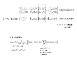
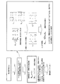
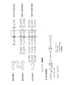
図7は、その処理の過程で作成する正規方程式を示す。
この図7に示される正規方程式においては、次数が2次の場合の正規方程式を式(1)として示し、次数を下げた1次の場合の正規方程式を式(2)として示している。
FIG. 7 shows a normal equation created during the process.
In the normal equation shown in FIG. 7, the normal equation when the order is second order is shown as equation (1), and the normal equation when the order is lowered is shown as equation (2).

式(1)と式(2)において、左辺が相関行列とAR係数ベクトルとの積であり、右辺が右辺ベクトルである。相関行列の要素又は右辺ベクトルの要素であるCxM(*,*)、及びAR係数ベクトルの要素であるaMは、それぞれが複素数である。なお、MがARモデルの次数(ARモデル次数)を示す。
また、相関行列の要素又は右辺ベクトルの要素であるCxM(*,*)は、式(3)として示される改良共分散関数から導かれる。
In equations (1) and (2), the left side is the product of the correlation matrix and the AR coefficient vector, and the right side is the right side vector. Each of C xM (*, *) that is an element of a correlation matrix or an element of a right-hand side vector, and a M that is an element of an AR coefficient vector are complex numbers. M represents the order of the AR model (AR model order).
Further, C xM (*, *) that is an element of the correlation matrix or an element of the right-hand side vector is derived from an improved covariance function expressed as Expression (3).
式(3)において、x(n)が入力データを示し、Nがデータ数を示し、MがARモデルの次数(ARモデル次数)を示し、x(n−j)又はx(n+k)の添え字の「*」が複素共役を示し、kとjが変数を示す。
例えば、式(1)、式(2)を解くことによりAR係数ベクトル(AR係数)を求めることができる。そのAR係数から、受信波数と角度とを以下に示す方法により求めることができる。AR係数から、受信波数と角度とを求める第1の方法は、単位円をサーチすることによりパワースペクトルを求める方法である。その第2の方法は、高次多項式の解(根)を求める方法である。
In Expression (3), x (n) indicates input data, N indicates the number of data, M indicates the order of the AR model (AR model order), and x (n−j) or x (n + k) is appended. The letter “*” indicates a complex conjugate, and k and j indicate variables.
For example, the AR coefficient vector (AR coefficient) can be obtained by solving Expression (1) and Expression (2). From the AR coefficient, the received wave number and angle can be obtained by the following method. The first method for obtaining the received wave number and angle from the AR coefficient is a method for obtaining a power spectrum by searching for a unit circle. The second method is a method for obtaining a solution (root) of a high-order polynomial.
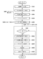
ここで、図8は、前述のステップS003からS005までの詳細な処理の手順を示すフローチャートである。図4と同じ処理には、同じ符号を附す。
ステップS003において方位スペクトル算出部30Aによって行われる処理を、例えばステップS301からS304に示すように分解することができる。
まず、ステップS301において、複素数データを抽出する。
ステップS302において、抽出した複素数データに基づいて、次数を2次とした正規方程式を作成する。
ステップS303において、作成した次数を2次とした正規方程式を解いて、AR係数と白色雑音の分散値とを算出する。正規方程式を解く計算としては、コレスキー分解などの計算方法を使用できる。
ステップS304において、次数を2次として算出したAR係数と白色雑音の分散値とからパワースペクトルを算出する。
そして、前述したようにターゲット抽出部24は、ステップS004において、算出されたパワースペクトルに基づいて、ピーク数と角度が検知される。
Here, FIG. 8 is a flowchart showing a detailed processing procedure from the above-described steps S003 to S005. The same processes as those in FIG. 4 are denoted by the same reference numerals.
The processing performed by the azimuth spectrum calculation unit 30A in step S003 can be decomposed as shown in steps S301 to S304, for example.
First, in step S301, complex number data is extracted.
In step S302, a normal equation having a second order is created based on the extracted complex number data.
In step S303, an AR coefficient and a dispersion value of white noise are calculated by solving a normal equation in which the created order is quadratic. As a calculation for solving a normal equation, a calculation method such as Cholesky decomposition can be used.
In step S304, a power spectrum is calculated from the AR coefficient calculated with the order being second order and the dispersion value of white noise.
Then, as described above, in step S004, the
また、ステップS005においてターゲット抽出部24によって行われる処理を例えばステップS501からS506に示すように分解することができる。
まず、ステップS501において、ステップS004によって検知されたピーク数が2であるか否かを判定する。その判定の結果、ピーク数が2でない(ステップS501:NO)である場合、相対レベル差算出処理(ステップS005)を終える。一方、その判定の結果、ピーク数が2である(ステップS501:YES)場合、ステップS502の処理に進む。
In addition, the process performed by the
First, in step S501, it is determined whether or not the number of peaks detected in step S004 is two. As a result of the determination, if the number of peaks is not 2 (step S501: NO), the relative level difference calculation process (step S005) ends. On the other hand, as a result of the determination, if the number of peaks is 2 (step S501: YES), the process proceeds to step S502.
ステップS502において、抽出した複素数データに基づいて、次数を1次とした正規方程式を作成する。
ステップS503において、作成した次数を1次とした正規方程式を解いて、AR係数と白色雑音の分散値とを算出する。
ステップS504において、次数を1次として算出したAR係数と白色雑音の分散値とからパワースペクトルを算出する。
ステップS505において、算出されたパワースペクトルに基づいて、ピークの角度が検知される。
ステップS506において、ステップS505において検知されたピークの角度に基づいて、後述する相対レベル差算出処理を行い、相対レベル差算出処理(ステップS005)を終える。
In step S502, based on the extracted complex number data, a normal equation having a first order is created.
In step S503, a normal equation with the created order as the first order is solved to calculate the AR coefficient and the white noise variance.
In step S504, a power spectrum is calculated from the AR coefficient calculated with the order being the first order and the variance value of the white noise.
In step S505, the peak angle is detected based on the calculated power spectrum.
In step S506, based on the peak angle detected in step S505, a relative level difference calculation process described later is performed, and the relative level difference calculation process (step S005) is completed.
(相対レベル差算出処理の原理)
次に、2つのターゲットの方位スペクトルを推定する場合を例にして相対レベル差算出処理の原理について示す。
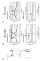
図9は、2つのターゲットに対して、次数を2次として推定されたスペクトル(方位スペクトル)と、次数を1次として推定されたスペクトル(方位スペクトル)とを示す図である。
図9(a)に示すように、電子走査型レーダ装置100Aを搭載した車両の前方正面と、前方正面より角度θ1(例えば、4.8deg(度))だけ左に寄った位置とにターゲットが配置された場合を示している。
図9(b)は、ターゲットの受信相対レベル差が等しい場合の、スペクトル推定結果を示す。次数を2次として推定されたスペクトルが示す2つのピークPb21、Pb22の角度は、それぞれ+4.8度と0度を示す。
縦軸によって示されるパワーの値は、繰り返して検出を行うと検出されたタイミングに応じて変動する。そのため、図9(b)は、ある特定のタイミングに検出されたパワーの波形を3データ分重ねて示すものであり、また、繰り返し検出された結果をさらに多く重ねて示す場合には、図中の矢印によって示される範囲でピークの値がさらに変動する。そのため、この図9(b)に示される波形、すなわちスペクトルの波形によって示されるピークの値からは、相対レベル差を得ることができない。
このような条件により検出されるターゲットを、次数を1次としてスペクトル推定した結果を対比して示す。次数を1次として推定されたスペクトルのピークは、安定したパワーレベルで2.4(度)に表れる。つまり、次数を1次として推定されたスペクトルのピークは、2つのターゲットをみなす角であるθ1の半分の角度として検出することが可能となる。
(Principle of relative level difference calculation process)
Next, the principle of relative level difference calculation processing will be described by taking as an example the case of estimating the orientation spectra of two targets.
FIG. 9 is a diagram showing, for two targets, a spectrum (azimuth spectrum) estimated as the second order and a spectrum (azimuth spectrum) estimated as the first order.
As shown in FIG. 9 (a), the target is located at the front front of the vehicle on which the electronic scanning radar apparatus 100A is mounted and at a position left to the left by an angle θ1 (for example, 4.8 deg (degrees)) from the front front. The case where it is arranged is shown.
FIG. 9B shows the spectrum estimation result when the reception relative level differences of the targets are equal. The angles of the two peaks Pb21 and Pb22 indicated by the spectrum estimated with the order as the second order are +4.8 degrees and 0 degrees, respectively.
The power value indicated by the vertical axis fluctuates according to the detected timing when repeated detection is performed. For this reason, FIG. 9B shows the waveform of the power detected at a certain specific timing by superimposing three data, and in the case where the results of repeated detection are further superimposed, The peak value further varies within the range indicated by the arrow. Therefore, a relative level difference cannot be obtained from the waveform shown in FIG. 9B, that is, the peak value indicated by the spectrum waveform.
The target detected under such conditions is shown in comparison with the results of spectrum estimation with the order being the first order. The peak of the spectrum estimated with the order as the first order appears at 2.4 (degrees) at a stable power level. In other words, the peak of the spectrum estimated with the order as the first order can be detected as a half angle of θ1, which is an angle for considering two targets.
一方、図9(c)は、左のターゲットの方が右のターゲットより受信相対レベルが大きい場合の、スペクトル推定結果を示す。次数を2次として推定されたスペクトルが示す2つのピークPb21、Pb22の角度は、それぞれ+4.8度と0度を示す。
縦軸によって示されるパワーの値は、繰り返して検出を行うと検出されたタイミングに応じて変動する。そのため、図9(c)は、ある特定のタイミングに検出されたパワーの波形を3データ分重ねて示すものであり、また、繰り返し検出された結果をさらに多く重ねて示す場合には、図中の矢印によって示される範囲でピークの値がさらに変動する。そのため、この図9(c)に示される波形、すなわちスペクトルの波形によって示されるピークの値からは、相対レベル差を得ることができない。
しかし、次数を1次として推定されたスペクトルのピークは、2次のスペクトルにおいて検出されたピークPc21側に寄った角度として安定して検出される。
このように、次数を1次としてスペクトル推定した結果のスペクトルは、相対レベル差が同じ場合には2ターゲットの中心の角度を示すが、相対レベル差が生じるとレベルの高い方に引き寄せられる。これは、ARスペクトル推定が、受信波の振幅レベルの高い方に合わせて近似させようとすることにより生じる。
On the other hand, FIG. 9C shows the spectrum estimation result when the left target has a higher reception relative level than the right target. The angles of the two peaks Pb21 and Pb22 indicated by the spectrum estimated with the order as the second order are +4.8 degrees and 0 degrees, respectively.
The power value indicated by the vertical axis fluctuates according to the detected timing when repeated detection is performed. For this reason, FIG. 9C shows the waveform of the power detected at a certain specific timing by superimposing three data, and when the results of repeated detection are further superimposed, The peak value further varies within the range indicated by the arrow. Therefore, a relative level difference cannot be obtained from the waveform shown in FIG. 9C, that is, the peak value indicated by the spectrum waveform.
However, the peak of the spectrum estimated with the order as the primary is stably detected as an angle close to the peak Pc21 detected in the secondary spectrum.
Thus, the spectrum obtained as a result of spectrum estimation with the order being the first order indicates the angle of the center of the two targets when the relative level difference is the same, but when the relative level difference occurs, the spectrum is drawn toward the higher level. This is caused by the fact that the AR spectrum estimation tries to approximate to the higher amplitude level of the received wave.
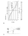
図10は、2つの受信波の振幅レベル差によるピーク角度の変化を示す図である。
この図10に示されるグラフは、図9に示したように、2つのターゲットからの受信波の振幅レベルを変化させた場合に、検出されるピーク角度が変化する様子を示している。
図9(a)に示したように2つのターゲットのみなし角度θ1を所定の角度(例えば、θ1=4.8deg)に定めた場合について示す。このグラフは、縦軸が検出されたピーク角度、横軸が左右の相対レベル差を示す。横軸は、左になるほど左側のターゲットからの受信波の振幅(レベル)が大きく、右になるほど右側のターゲット、すなわち正面のターゲットからの受信波の振幅が大きくなることを示す。
左右の相対レベル差を変化させて、ピークの角度をグラフにプロットし、相関式(多項式)にて近似する。
このグラフに示されるように、中心角度(この場合、2.4deg)を基準に、対称に分布するので、相関式には多項式近似で対応できる。本実施形態によれば、この相関式により、±10dBの範囲であれば正確な左右レベル差を算出することが可能となる。また、±10dB以上のレベル差が生じていたとしても、振幅レベルの大きい方の角度に近づくので、振幅レベルのレベル差が大きいと判断できる。
このように、複数のピーク間の角度の差と、複数のピーク間の相対レベル差との関係を示す相関式に従って、ターゲット抽出部24は、次数を下げて算出されたスペクトル(第2の方位スペクトル)に基づいて算出されたピーク角度に基づいて相対レベル差を算出する。
FIG. 10 is a diagram illustrating a change in peak angle due to a difference in amplitude level between two received waves.
The graph shown in FIG. 10 shows how the detected peak angle changes when the amplitude levels of the received waves from the two targets are changed, as shown in FIG.
As shown in FIG. 9A, the case where the angle θ1 having only two targets is set to a predetermined angle (for example, θ1 = 4.8 deg) will be described. In this graph, the vertical axis indicates the detected peak angle, and the horizontal axis indicates the relative level difference between the left and right. The horizontal axis indicates that the amplitude (level) of the received wave from the left target increases as it goes to the left, and the amplitude of the received wave from the right target, that is, the front target increases, as it goes to the right.
By changing the relative level difference between the left and right, the peak angle is plotted on a graph and approximated by a correlation equation (polynomial).
As shown in this graph, since the distribution is symmetrical with respect to the center angle (in this case, 2.4 deg), the correlation equation can be handled by polynomial approximation. According to the present embodiment, it is possible to calculate an accurate left / right level difference within the range of ± 10 dB from this correlation equation. Even if a level difference of ± 10 dB or more occurs, the angle approaches the angle with the larger amplitude level, so it can be determined that the level difference of the amplitude level is large.
As described above, the
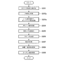
図4に戻り、ステップS006において、ターゲット抽出部24は、グループ化処理として、後ステップの組合せ処理を行い易くするため、検出されたピークをターゲット単位にグループ化する。そのグループ化には、1つ1つの(個々の)ピークを基準にして、ターゲットに対する距離方向と角度方向とにおいて予め定められる所定の距離と角度を基準とする領域を単位としてグループ化する。そして、同一の距離ポイントに存在するグループが単数である場合のグループと、複数である場合にグループとに分ける。またそれぞれのグループには、平均距離、平均角度の情報を持たせる。複数のグループには、そのグループ間の振幅レベルのレベル差を示す平均相対レベル差の情報をさらに持たせる(図11参照)。
Returning to FIG. 4, in step S006, the
ステップS007において、ターゲット抽出部24は、上記のステップS006まで個別に処理してきた上りと下りのグループについて組合せる組合せ処理を行う。
図12(a)は、角度情報だけでは複数の組合せパターンが存在する場合の一例を示している。このような場合であっても、グループの組合せを相対レベル差に基づいて行うことよってグループ化できる。
例えば、同一のグループであると判定する条件を、次のように定めるとする。
それぞれのグループの角度が一致するか否かを判定条件とする、すなわち、基準とするピークを中心として所定の角度範囲(±α(deg))に含まれる角度範囲であるか否かを判定条件とする。
かつ、それぞれのグループの相対レベル差が一致するか否かを判定条件とする、すなわち、基準とするピークの相対レベル差が所定の相対レベル差の範囲(±β(dB))に含まれるレベル範囲であるか否かを判定条件とする。
図12(a)では、相対レベル+5dBの組み合わせ(レベル+5dB)と、相対レベル−2dBの組み合わせ(レベル−2dB)が決定する。なお、組合せの条件は、図12に示した形態に限られず、前回サイクルの確定結果からの予測など、公知の手法との併用が可能である。
In step S007, the
FIG. 12A shows an example in the case where a plurality of combination patterns exist only with the angle information. Even in such a case, groups can be grouped by performing group combinations based on relative level differences.
For example, it is assumed that the conditions for determining the same group are determined as follows.
The determination condition is whether or not the angles of the respective groups match. That is, the determination condition is whether or not the angle range is included in a predetermined angle range (± α (deg)) around the reference peak. And
In addition, the determination condition is whether or not the relative level differences of the respective groups match. That is, the level in which the relative level difference of the reference peak is included in a predetermined relative level difference range (± β (dB)) Whether it is a range or not is set as a determination condition.
In FIG. 12A, the combination of the relative level +5 dB (level +5 dB) and the combination of the relative level −2 dB (level −2 dB) are determined. Note that the combination conditions are not limited to the form shown in FIG. 12, and can be used in combination with a known method such as prediction from the final cycle final result.
図4に戻り、続いて、ステップS008において、組合せたグループにおける距離と相対速度を算出し、ステップS009において、既知の角度を含めてターゲットを確定する。 Returning to FIG. 4, subsequently, in step S008, the distance and relative speed in the combined group are calculated, and in step S009, the target including the known angle is determined.
このように、電子走査型レーダ装置100Aは、自己回帰モデルを用いるスペクトル推定法により、受信波の到来方向を算出することができる。
なお、本実施形態において、周波数分解レベル検知部23が第1手段として機能する。方位スペクトル算出部30Aが第2手段として機能する。ターゲット抽出部24が第3手段として機能する。
As described above, the electronic scanning radar apparatus 100A can calculate the arrival direction of the received wave by the spectrum estimation method using the autoregressive model.
In the present embodiment, the frequency
(第2実施形態)
次に、図13から図20を参照し、本実施形態による電子走査型レーダ装置について説明する。
本実施形態では固有値計算による次数推定を行う。例えば、3次の正規方程式の共分散行列から固有値を計算し、その固有値から次数推定を行う。ここでは、固有値計算により算出される最大(又は総和)の固有値に基づいて判定することにより、前述の周波数分解レベル検知部23と同様に、ビート信号の振幅レベルを判定する閾値を設け、連続した多ポイントが検知できるようにする。
また、次数推定の過程において、2次と推定された場合には、1次と2次のARスペクトル推定をそれぞれ行う。
(Second Embodiment)
Next, the electronic scanning radar apparatus according to the present embodiment will be described with reference to FIGS.
In the present embodiment, the order is estimated by eigenvalue calculation. For example, an eigenvalue is calculated from a covariance matrix of a cubic normal equation, and the order is estimated from the eigenvalue. Here, by determining based on the maximum (or total) eigenvalue calculated by eigenvalue calculation, a threshold for determining the amplitude level of the beat signal is provided in the same manner as the frequency resolution
In the order estimation process, when it is estimated to be second order, first and second order AR spectrum estimation is performed.
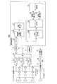
図13は、本実施形態による電子走査型レーダ装置の構成例を示すブロック図である。
本実施形態における信号処理部20Bは、第1実施形態と同様に、方位推定を高分解能アルゴリズムで行う。図1に示す第1実施形態と同じ構成については、同一の符号を付し、以下第1実施形態との相違点について説明する。
この図において、本実施形態による電子走査型レーダ装置100Bは、受信アンテナ1−1〜1−n、ミキサ2−1〜2−n、送信アンテナ3、分配器4、フィルタ5−1〜5―n、SW(スイッチ)6、ADC(A/Dコンバータ)7、制御部8、三角波生成部9、VCO10、信号処理部20Bを備える。
信号処理部20Bは、メモリ21、周波数分離処理部22B、次数推定部27、ターゲット抽出部24、距離検出部25、速度検出部26、ターゲット確定部31、及び、方位スペクトル算出部30Bを備える。
FIG. 13 is a block diagram illustrating a configuration example of the electronic scanning radar apparatus according to the present embodiment.
Similar to the first embodiment, the
In this figure, the electronic scanning radar apparatus 100B according to the present embodiment includes receiving antennas 1-1 to 1-n, mixers 2-1 to 2-n, a transmitting antenna 3, a
The
信号処理部20Bにおいて周波数分解処理部22Bは、アンテナ毎の上昇領域と下降領域とのビート信号を複素数データに変換し、そのビート周波数を示す周波数ポイントと、複素数データとを次数推定部27へ出力する。
次に、周波数分解処理部22Bは、上昇領域及び下降領域それぞれについて該当する複素数データを、方位スペクトル算出部30Bへ出力する。この複素数データが、上昇領域及び下降領域のそれぞれのターゲット群(上昇領域及び下降領域において連続した特定のビート周波数)となる。
次数推定部27は、供給される複素数データに基づいて次数推定を行う。ここで、次数推定部27は、モデル次数推定処理における最大固有値判定を行う。
方位スペクトル算出部30Bは、次数推定部27によって推定された結果により、2次と推定された周波数ポイントについて、次数を2次と1次とするスペクトル推定処理を行う。
方位スペクトル算出部30Bは、上昇部分(上り)及び下降部分(下り)共、レベル検知範囲(つまり抽出された複素数データ)の、ARスペクトル(=パワースペクトル)を算出する。
なお、方位スペクトル算出部30Bは、改良共分散法(=前向き後向き線形予測法)によるARスペクトル推定を実施するものとして説明するが、バーグ(Burg)法等の他のスペクトル推定法を利用することもできる。
また、方位スペクトル算出部30Bは、AR係数を算出する際に、同時に白色雑音の分散値も算出する。
In the
Next, the frequency
The
The azimuth
The azimuth
The azimuth
Further, the azimuth
続いて、図14から図20を参照し、信号処理部20Bにおける受信波に対する信号処理について示す。
図14は、信号処理部20Bにおける処理の手順を示すフローチャートである。図4、図8と同じ処理を行うステップには、同じ符号を附す。
図15から図20は、図14に示される処理を説明する図である。
Next, with reference to FIG. 14 to FIG. 20, signal processing for the received wave in the
FIG. 14 is a flowchart illustrating a processing procedure in the
15 to 20 are diagrams illustrating the processing shown in FIG.
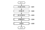
ステップS002aにおいて、次数推定部27は、複素数データに基づいて作成される正規方程式の構成部である行列から、算出された固有値に基づいた次数推定処理を行う。
図15は、次数推定部27による次数推定処理の一実施手順を示すフローチャートである。
ステップS002aの処理として、ステップS201において、次数推定部27は、正規方程式の構成部である共分散行列(又は自己相関行列)を作成し、ユニタリ変換を行う。
ステップS202において、次数推定部27は、ユニタリ変換された行列(共分散行列又は自己相関行列)の固有値を算出する。
図16は、固有値計算について示す図である。
ユニタリ変換を行うことにより、実数の相関行列に変換することができ、以降におけるステップでの最も計算負荷の重い固有値計算が実数のみの計算とすることができ、大幅に演算負荷を軽減することができる。
本実施形態に示すように次数を3次とした場合には、ユニタリ変換による、エルミート行列の実数相関行列(対称行列)化は、式(4)として示される演算式によって行うことができる(一般式は、参考文献(菊間、「アダプティブアンテナ技術」(オーム社、2003年、pp158-160)を参照)。
In step S002a, the
FIG. 15 is a flowchart showing an implementation procedure of the order estimation processing by the
As step S002a, in step S201, the
In step S202, the
FIG. 16 is a diagram illustrating eigenvalue calculation.
By performing unitary transformation, it can be converted into a real correlation matrix, and the eigenvalue calculation with the most computational load in subsequent steps can be made only with real numbers, which can greatly reduce the computation load. it can.
As shown in the present embodiment, when the order is set to the third order, the real number correlation matrix (symmetric matrix) conversion of the Hermitian matrix by the unitary transformation can be performed by an arithmetic expression shown as Expression (4) (general) For the formula, see Reference (Kikuma, “Adaptive Antenna Technology” (Ohm, 2003, pp158-160)).
式(4)において、右肩に付したHは、エルミート転置を示す。
なお、このユニタリ変換を行うことにより、後段処理の固有値計算の負荷を軽減させることができ、また、信号相関抑圧効果も期待できる。そのため、ユニタリ変換による実数相関行列への変換を行わずに、次のステップにおける固有値計算も複素数で計算することも可能であるが、ユニタリ変換による実数相関行列への変換を実施することが望ましい。
また、固有値計算は、式(5)、式(6)として示す式によって行うことができる。
In Formula (4), H attached to the right shoulder indicates Hermitian transposition.
By performing this unitary conversion, it is possible to reduce the load of calculation of eigenvalues in subsequent processing, and to expect a signal correlation suppression effect. Therefore, the eigenvalue calculation in the next step can be calculated as a complex number without performing conversion to a real correlation matrix by unitary conversion, but it is desirable to perform conversion to a real correlation matrix by unitary conversion.
Further, the eigenvalue calculation can be performed by the equations shown as Equation (5) and Equation (6).
固有値計算は、固有ベクトルの処理を削減したもので良く、式(6)の固有方程式を直接解く他、任意の解法アルゴリズムを適用できる。例えば、ヤコビ法、ハウスホルダ法、QR法等の反復計算タイプのアルゴリズムも適用できる。 The eigenvalue calculation may be performed by reducing the processing of the eigenvector, and an arbitrary solution algorithm can be applied in addition to directly solving the eigenequation of Equation (6). For example, iterative calculation type algorithms such as the Jacobian method, the house holder method, and the QR method can be applied.
図15に戻り、ステップS203において、得られた最大となる固有値(最大固有値)を判定する。ステップS204において、次数推定部27は、算出された固有値が予め定めた閾値以上の値を示した場合には、それぞれ算出された固有値を、算出された固有値の最大の値に基づいて正規化する。
ステップS205において、次数推定部27は、正規化された固有値の値を予め定められる閾値に基づいて判定し、その判定結果に基づいて後段の処理の次数を選択する。
上記のステップS203からS205までの一連の処理をモデル次数推定処理と呼ぶ。ステップS203からS205に示すモデル次数推定処理の具体的な実施態様については、後述する。
また、図14に戻り、ステップS003aにおいて、方位スペクトル算出部30Bは、推定された次数に従ってARスペクトル算出処理の次数を定め、ARスペクトルの算出処理を行う。
Returning to FIG. 15, in step S203, the obtained maximum eigenvalue (maximum eigenvalue) is determined. In step S204, when the calculated eigenvalue indicates a value equal to or greater than a predetermined threshold, the
In step S205, the
A series of processing from step S203 to S205 is referred to as model order estimation processing. A specific embodiment of the model order estimation process shown in steps S203 to S205 will be described later.
Returning to FIG. 14, in step S003a, the orientation
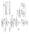
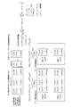
図17は、図15のステップ203からステップS205までに示したモデル次数推定処理の詳細を示す図である。
ステップS203aは、ステップS203に対応する最大固有値判定処理である。ステップS203aによる判定により、予め設定した閾値(λmax_th)よりも最大固有値の値(λa)が小さい場合(ステップS203a:No)には、ステップS203bにおいて、得られた情報(複素数データ)から反射レベルが小さな物体であると判定し、次数推定部27は、該当ターゲットに対しての次ステップの次数推定処理及び方位検知処理を行わなくする。最大固有値は、入力信号の強度と等価(比例する)であることから、路面マルチパス等の車載用レーダ特有のクラッタ状況による信号を受信するような場合であっても、最大固有値の値を判定することにより、間違った方位推定となることを抑制することができる。また、次数推定部27は、最大固有値の代わりに、算出した固有値の総和(又は、元の相関行列の対角要素の和)を用いて判定しても良い。
つまり、このステップS203bでは、次数推定及び方位検出の双方をキャンセルすることができるので、第1実施形態の周波数レベル検知(ステップS002)と同様の機能を持たせることができる。
FIG. 17 is a diagram showing details of the model order estimation processing shown from step 203 to step S205 in FIG.
Step S203a is a maximum eigenvalue determination process corresponding to step S203. If the maximum eigenvalue value (λa) is smaller than the preset threshold value (λmax_th) by the determination in step S203a (step S203a: No), the reflection level is determined from the information (complex number data) obtained in step S203b. The
That is, in step S203b, both order estimation and azimuth detection can be canceled, so that the same function as the frequency level detection (step S002) of the first embodiment can be provided.
ステップS203aによる判定により、予め設定した閾値よりも最大固有値の値が小さくない場合(ステップS203a:Yes)には、ステップS204aの処理は、ステップS204に対応する固有値の正規化処理であり、各固有値λxを最大固有値λaでそれぞれ除算した値を正規化固有値λyとする。レーダのように、ターゲットとの距離によって固有値(信号強度)が変動する場合は、正規化して相対的に固有値間の大小関係を判定した方が、容易に判定できる。 If the maximum eigenvalue value is not smaller than the preset threshold value as a result of determination in step S203a (step S203a: Yes), the process in step S204a is a process for normalizing eigenvalues corresponding to step S204. A value obtained by dividing λx by the maximum eigenvalue λa is defined as a normalized eigenvalue λy. When the eigenvalue (signal intensity) varies depending on the distance to the target as in a radar, it can be easily determined by normalizing and relatively determining the magnitude relationship between eigenvalues.
ステップS205aからS205eまでは、次数推定部27が行うステップS205に対応する次数推定処理である。
ステップS205aでは、ステップS204aにおいて正規化処理された固有値の中から2番目に大きな固有値(正規化第2固有値)を選択し、正規化第2固有値が予め定められる閾値Th1より小さいか否かを判定する。判定の結果、正規化第2固有値が予め定められる閾値Th1より小さくないと判定した場合(ステップS205a:No)には、ステップS205cに進む。
Steps S205a to S205e are the order estimation process corresponding to step S205 performed by the
In step S205a, the second largest eigenvalue (normalized second eigenvalue) is selected from the eigenvalues normalized in step S204a, and it is determined whether the normalized second eigenvalue is smaller than a predetermined threshold Th1. To do. As a result of the determination, when it is determined that the normalized second eigenvalue is not smaller than the predetermined threshold Th1 (step S205a: No), the process proceeds to step S205c.
ステップ205bでは、ステップS205aにおける判定の結果、正規化第2固有値が予め定められる閾値Th1より小さいと判定した場合(ステップS205a:Yes)には、推定次数を1次に定め、図示されない推定次数情報を記憶する記憶領域に記録し、次数推定処理を終える。 In step 205b, when it is determined that the normalized second eigenvalue is smaller than the predetermined threshold Th1 as a result of the determination in step S205a (step S205a: Yes), the estimated order is determined to be primary, and estimated order information (not shown) Is stored in the storage area for storing the order, and the order estimation process is completed.
ステップS205cでは、ステップS204aにおいて正規化処理された固有値の中から3番目に大きな固有値(正規化第3固有値)を選択し、正規化第3固有値が予め定められる閾値Th2より小さいか否かを判定する。判定の結果、正規化第3固有値が予め定められる閾値Th2より小さくないと判定した場合(ステップS205c:No)には、ステップS205eに進む。 In step S205c, the third largest eigenvalue (normalized third eigenvalue) is selected from the eigenvalues normalized in step S204a, and it is determined whether the normalized third eigenvalue is smaller than a predetermined threshold Th2. To do. As a result of the determination, when it is determined that the normalized third eigenvalue is not smaller than a predetermined threshold Th2 (step S205c: No), the process proceeds to step S205e.
ステップ205dでは、ステップS205cにおける判定の結果、正規化第3固有値が予め定められる閾値Th2より小さいと判定した場合(ステップS205c:Yes)には、推定次数を2次に定め、図示されない推定次数情報を記憶する記憶領域に記録し、次数推定処理を終える。 In step 205d, when it is determined that the normalized third eigenvalue is smaller than the predetermined threshold Th2 as a result of the determination in step S205c (step S205c: Yes), the estimated order is determined to be second and estimated order information not shown in the figure. Is stored in the storage area for storing the order, and the order estimation process is completed.
ステップ205eでは、ステップS205cにおける判定の結果、正規化第3固有値が予め定められる閾値Th2より小さくないと判定した場合(ステップS205c:No)には、推定次数を3次に定め、図示されない推定次数情報を記憶する記憶領域に記録し、次数推定処理を終える。 In step 205e, when it is determined that the normalized third eigenvalue is not smaller than the predetermined threshold Th2 as a result of the determination in step S205c (step S205c: No), the estimated order is determined to be third and an estimated order (not shown) The information is recorded in a storage area for storing information, and the order estimation process is completed.
このようにステップS205aからS205eまでの次数推定処理において、次数1と次数2以上とを分別する閾値Th1と、次数2と次数3とを分別する閾値Th2の2種類の閾値で構成している。このような閾値の構成とすることにより、複数のターゲットの時に、ARスペクトル推定精度に有利な高次設定寄りに設定できるので、ARスペクトル推定を用いた車載用レーダ特有の設定に適用できる。
As described above, in the order estimation process from step S205a to S205e, the threshold value Th1 for classifying the
図18は、その処理の過程で作成する正規方程式を示す。
ここ図に示される正規方程式においては、次数が1次から3次の場合の正規方程式を式(7)から式(9)として、それぞれ示している。
FIG. 18 shows a normal equation created during the process.
In the normal equations shown in this figure, the normal equations when the order is from the first order to the third order are shown as Expressions (7) to (9), respectively.
式(7)から式(9)において、左辺が相関行列とAR係数ベクトルとの積であり、右辺が右辺ベクトルである。相関行列の要素又は右辺ベクトルの要素であるCxM(*,*)、及びAR係数ベクトルの要素であるaMは、それぞれが複素数である。なお、MがARモデルの次数(ARモデル次数)を示す。
また、相関行列の要素又は右辺ベクトルの要素であるCxM(*,*)は、式(10)として示される改良共分散関数から導かれる。
In Expressions (7) to (9), the left side is the product of the correlation matrix and the AR coefficient vector, and the right side is the right side vector. Each of C xM (*, *) that is an element of a correlation matrix or an element of a right-hand side vector, and a M that is an element of an AR coefficient vector are complex numbers. M represents the order of the AR model (AR model order).
Further, C xM (*, *) that is an element of the correlation matrix or an element of the right-hand side vector is derived from an improved covariance function expressed as Expression (10).
式(10)において、x(n)が入力データを示し、Nがデータ数を示し、MがARモデルの次数(ARモデル次数)を示し、x(n−j)又はx(n+k)の添え字の「*」が複素共役を示し、kとjが変数を示す。
例えば、式(7)から式(9)を解くことによりAR係数ベクトル(AR係数)を求めることができる。そのAR係数から、受信波数と角度とを以下に示す方法により求めることができる。AR係数から、受信波数と角度とを求める第1の方法は、単位円をサーチすることによりパワースペクトルを求める方法である。その第2の方法は、高次多項式の解(根)を求める方法である。
方位スペクトル算出部30Bは、推定次数に応じて、正規方程式の次数を定める。方位スペクトル算出部30Bは、推定次数が1の場合は、次数1の正規方程式に基づいてAR係数ベクトルを求め、推定次数が2の場合は、次数1と次数2の正規方程式に基づいてAR係数ベクトルを求め、推定次数が3の場合は、次数3の正規方程式に基づいてAR係数ベクトルを求める。
In Expression (10), x (n) indicates input data, N indicates the number of data, M indicates the order of the AR model (AR model order), and x (n−j) or x (n + k) is attached. The letter “*” indicates a complex conjugate, and k and j indicate variables.
For example, the AR coefficient vector (AR coefficient) can be obtained by solving Expression (9) from Expression (7). From the AR coefficient, the received wave number and angle can be obtained by the following method. The first method for obtaining the received wave number and angle from the AR coefficient is a method for obtaining a power spectrum by searching for a unit circle. The second method is a method for obtaining a solution (root) of a high-order polynomial.
The orientation
次に、第1実施形態と第2実施形態において、同一制御サイクルでデータを多数取得する場合に適用できる例を示す。
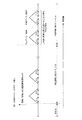
図19は、検知サイクルにおけるデータ取得処理を示すタイムチャートである。
図19には、今回制御(検知)サイクルからさかのぼって、過去に行われた過去制御(検知)サイクルが示されている。
各サイクルでは、少なくとも1回のデータ取得が行われ、1回のデータ取得を三角の波形で示す。三角の波形は、FMCW方式によって変調された信号を示し、右上がりのタイミングにおいて上り、右下がりのタイミングにおいて下りの検知が行われる。
個々のデータ取得は、干渉が生じないだけの時間間隔が確保され繰り返し行われ、三角波の周波数変調周期は、必ずしも同一でなくても良い。
今回制御(検知)サイクルにおいて、P回のデータ取得が行われ、1回目に行われたデータ取得を「今回データ_1取得」として示し、P回目に行われたデータ取得を「今回データ_P取得」として示す。
同じサイクル内で取得されたデータに基づいて、後に示す各種処理の平均化処理が行われる。
また、現在データ取得されている制御(検知)サイクルを「今回制御(検知)サイクル」といい、「今回制御(検知)サイクル」より過去に行われた制御(検知)サイクルを「過去制御(検知)サイクル」という。
Next, in the first embodiment and the second embodiment, an example that can be applied when a large number of data is acquired in the same control cycle will be described.
FIG. 19 is a time chart showing data acquisition processing in the detection cycle.
FIG. 19 shows past control (detection) cycles performed in the past from the current control (detection) cycle.
In each cycle, at least one data acquisition is performed, and one data acquisition is indicated by a triangular waveform. A triangular waveform indicates a signal modulated by the FMCW system, and detection is performed at an upward timing and at a downward timing.
Individual data acquisition is repeatedly performed with a time interval sufficient to prevent interference, and the frequency modulation period of the triangular wave does not necessarily have to be the same.
In the current control (detection) cycle, P data acquisition is performed, the first data acquisition is indicated as “current data_1 acquisition”, and the data acquisition performed in the Pth time is “current data_P acquisition”. As shown.
Based on the data acquired in the same cycle, an averaging process of various processes described later is performed.
In addition, the control (detection) cycle for which data is currently acquired is called the “current control (detection) cycle”, and the control (detection) cycle performed before the “current control (detection) cycle” is referred to as “past control (detection) cycle”. ) Cycle.
<ARモデルを用いた正規方程式の作成処理の原理>
次に、ARモデルを用いた正規方程式の作成処理について、改良共分散法を例にして詳細に示す。
共分散行列を用いた正規方程式を式(11)に示す。
<Principle of normal equation creation process using AR model>
Next, a process for creating a normal equation using an AR model will be described in detail using an improved covariance method as an example.
A normal equation using a covariance matrix is shown in Equation (11).
式(11)において、左辺が共分散行列CxxとAR係数ベクトルaの積であり、右辺が右辺ベクトルcxxである。
共分散行列Cxxの要素は、式(12)として示される関係式によって導かれる。
In equation (11), the left side is the product of the covariance matrix C xx and the AR coefficient vector a, and the right side is the right side vector c xx .
The elements of the covariance matrix C xx are derived by the relational expression shown as Expression (12).
以下、具体的な構成として5チャンネルのデータから3次の処理を行う場合を例として示す(最大モデル次数は任意に設定できるが、5チャンネルのデータの場合、改良共分散法では3次が最大となる。データのチャンネル数をさらに多くできると、正規方程式に適用できる最大次数も大きくなり、適用する最大モデル次数の柔軟性が増す。)。
共分散行列Cxxは、3行3列の行列式で表すことができ、その式を式(13)として示す。
In the following, a specific configuration is shown as an example of performing third-order processing from 5-channel data (the maximum model order can be arbitrarily set, but in the case of 5-channel data, the third order is the maximum in the improved covariance method. (The more channels of data, the greater the maximum order that can be applied to the normal equation, and the greater the flexibility of the maximum model order that can be applied.)
The covariance matrix C xx can be expressed by a determinant of 3 rows and 3 columns, and the equation is expressed as Equation (13).
式(13)において、行列の各要素Cx3(k,j)は、複素数を示す。各要素について展開した演算式を合わせて示す。x(n)、すなわち、(x(0)、x(1)、x(2)、x(3)、x(4))は、それぞれが複素数データであり、「*」は、複素共役を示す。
式(13)に示されるように、共分散行列Cxxは、式(14)として示される関係があることから、エルミート行列(複素数対称行列)となる。
In Expression (13), each element C x3 (k, j) of the matrix represents a complex number. An arithmetic expression developed for each element is also shown. x (n), that is, (x (0), x (1), x (2), x (3), x (4)) are each complex number data, and “*” is a complex conjugate. Show.
As shown in Expression (13), the covariance matrix C xx is a Hermitian matrix (complex symmetric matrix) because of the relationship shown as Expression (14).
また、同様に、3次の処理を行う場合の右辺ベクトルcxxを式(15)として示す。 Similarly, a right side vector c xx in the case of performing the third order processing is shown as an expression (15).
入力白色雑音の分散σv 2を導く関係式を、式(16)として示す。 A relational expression for deriving the variance σ v 2 of the input white noise is shown as Expression (16).
ARモデルによる線形予測では、予測値と観測値の差(予測誤差)の最小2乗誤差、又は、平均2乗誤差が最小となる条件から、この正規方程式が導かれる。
この正規方程式を一般的な手法により解くことにより、AR係数が導かれる。
また、式(16)によって算出される入力白色雑音の分散σv 2に基づいて、パワースペクトルSxx(ω)を算出する演算式を式(17)として示す。
In the linear prediction by the AR model, this normal equation is derived from the condition that the least square error or the mean square error of the difference between the predicted value and the observed value (prediction error) is the minimum.
The AR coefficient is derived by solving this normal equation by a general method.
An arithmetic expression for calculating the power spectrum Sxx (ω) based on the variance σ v 2 of the input white noise calculated by Expression (16) is shown as Expression (17).
式(17)において、ωは角速度を示し、HAR(ω)は、角速度ωにおけるARフィルタの伝達関数からの周波数特性を示し、Svv(ω)は、角速度ωにおける入力白色雑音のパワースペクトルを示し、Svv(ω)=σv 2と表せる。ここの角速度ωは、本発明のレーダのような方向検出に利用する場合には、受信波の位相差に換算する。
以上に示した演算式を用いることにより、ターゲットの方向と合致したピークの特徴を持つスペクトルを導くことができる。
In Expression (17), ω represents an angular velocity, H AR (ω) represents a frequency characteristic from the transfer function of the AR filter at the angular velocity ω, and Svv (ω) represents a power spectrum of the input white noise at the angular velocity ω. And can be expressed as Svv (ω) = σ v 2 . Here, the angular velocity ω is converted into a phase difference of received waves when used for direction detection like the radar of the present invention.
By using the arithmetic expression shown above, it is possible to derive a spectrum having a peak characteristic that matches the target direction.
図20は、取得された複素数データに基づいたM次の正規方程式の構成と平均化処理を示す図である。
図20に示されるM次の正規方程式は、M次の正方行列である共分散行列と、M行1列のAR係数と、M行1列の右辺ベクトルを要素として構成される。
取得された複素数データに基づいて、共分散行列と、右辺ベクトルが生成される。AR係数は、正規方程式を解くことにより算出される。
FIG. 20 is a diagram illustrating a configuration of an M-th order normal equation based on acquired complex number data and an averaging process.
The M-th order normal equation shown in FIG. 20 includes a covariance matrix that is an M-order square matrix, an AR coefficient of M rows and 1 column, and a right-side vector of M rows and 1 column as elements.
A covariance matrix and a right-hand vector are generated based on the acquired complex number data. The AR coefficient is calculated by solving a normal equation.
図19に示したように1つの制御(検知)サイクルにおいて複数回のデータ所得が行われる。取得された複素数データを取得された順に、共分散行列Cxxk(t)と右辺ベクトルcxxk(t)が生成される。
図19において、1制御(検地)サイクルにおいてデータを取得する回数をP回とする。取得された回数に対応させて、「今回_1」、・・・、「今回_P」として順に、共分散行列Cxxk(t)と右辺ベクトルcxxk(t)を示す。
As shown in FIG. 19, data income is performed a plurality of times in one control (detection) cycle. A covariance matrix C xxk (t) and a right-side vector c xxk (t) are generated in the order in which the acquired complex data is acquired.
In FIG. 19, the number of times data is acquired in one control (landing) cycle is P times. The covariance matrix C xxk (t) and the right-side vector c xxk (t) are shown in order as “current time_1”,..., “ Current time_P ” corresponding to the acquired number of times.
本実施形態において、正規方程式の平均化処理では、同一制御(検知)サイクル内に取得されたデータに基づいて行われ、「今回_1」から「今回_P」までの共分散行列Cxxk(t)と右辺ベクトルcxxk(t)を構成する要素をそれぞれ平均することにより、平均化処理が行われる。平均共分散行列Ave_Cxxk(t)を算出する演算式を式(18)に示す。 In the present embodiment, the normal equation averaging process is performed based on data acquired within the same control (detection) cycle, and the covariance matrix C xxk (t) from “ current_1 ” to “ current_P ”. And the right side vector c xxk (t) are averaged to perform the averaging process. An equation for calculating the average covariance matrix Ave_C xxk (t) is shown in Equation (18).
式(18)において、k1からkPは、加重平均を行う場合の重み計数である。
また、右辺ベクトルAve_cxxk(t)を算出する演算式を式(19)に示す。
In Equation (18), k1 to kP are weighting factors when performing weighted averaging.
Further, an arithmetic expression for calculating the right side vector Ave_c xxk (t) is shown in Expression (19).
式(19)において、k1からkPは、加重平均を行う場合の重み計数である。
また、平均化処理された正規方程式に基づいて、固有値を算出する場合には、平均化処理された正規方程式の共分散行列の固有値を算出する。
このように、データを多数取得する場合には、方位スペクトル算出部30Bは、周波数ポイントに対応させ、自己回帰モデルに基づいて生成された正規方程式の平均化処理をする。方位スペクトル算出部30Bが正規方程式を平均化することにより、方位スペクトル算出部30Bにより算出されるスペクトルが安定し、算出されるスペクトルの精度を向上させることができる。
In Equation (19), k1 to kP are weighting factors when performing weighted averaging.
In addition, when the eigenvalue is calculated based on the averaged normal equation, the eigenvalue of the covariance matrix of the averaged normal equation is calculated.
As described above, when a large number of data is acquired, the orientation
また、このように、電子走査型レーダ装置100Bは、自己回帰モデルを用いるスペクトル推定法により、DBFを用いない多ポイント方位推定の上りと下りの組合せ精度を向上させることができる。
なお、本実施形態において、次数推定部27が第4手段として機能する。方位スペクトル算出部30Bが第2手段として機能する。ターゲット抽出部24が第3手段として機能する。
As described above, the electronic scanning radar apparatus 100B can improve the combination accuracy of uplink and downlink of multipoint azimuth estimation without using DBF by the spectrum estimation method using the autoregressive model.
In the present embodiment, the
本実施形態による電子走査型レーダ装置は、検出ビート周波数の複素数データに基づいて、方位スペクトル算出部30Bでスペクトル推定を行う正規方程式の次数を設定して方位推定を行うことにより、検出精度を向上させることができる。
The electronic scanning radar apparatus according to the present embodiment improves detection accuracy by setting the order of a normal equation for performing spectrum estimation in the azimuth
本発明に係る第1実施形態によれば、ARスペクトル推定法を方位検出に応用した車載用レーダにおいて、特にDBFを用いない場合に、以下に述べる手段を備えることを特徴とする。
第1手段として、周波数分解レベル検知部23を設ける。ここでは、周波数分解レベル検知部23は、周波数分解部22で算出した結果に対して、スペクトル推定を行う周波数ポイント(=物理的にドップラーシフトを含めた距離であるが、便宜上距離ポイントと示す)を決定する。周波数分解レベル検知部23は、周波数分解されたレベルを検知する際に、そのレベルを判定する閾値を設け、連続した多ポイントが検知できるようにする。連続した多ポイントが検知できた領域(多ポイントの領域)の周波数ポイントに対して、後ステップの方位スペクトル推定を行う。
According to the first embodiment of the present invention, the vehicle-mounted radar that applies the AR spectrum estimation method to azimuth detection includes the following means, particularly when DBF is not used.
As a first means, a frequency
第2手段として、方位スペクトル算出部30Aを設ける。ここでは、第1手段で決定した多ポイントの領域で、ARスペクトル推定を行う。連続した多ポイントのピークを算出することによって、後ステップのグループ化(=ターゲット単位化)を行い易くすることができる。 As a second means, an orientation spectrum calculation unit 30A is provided. Here, AR spectrum estimation is performed in the multi-point region determined by the first means. By calculating continuous multipoint peaks, it is possible to facilitate grouping (= target unitization) of subsequent steps.
第3手段として、ターゲット抽出部24を設ける。ここでは、まず第2手段で算出したスペクトルのピークを検知し、ピーク数と角度を得る。同一距離ポイントに複数のピークがあることを判定した場合、次数を一つ下げたARスペクトル推定を行い、複数のピークのピーク角度と、次数を一つ下げたARスペクトル推定結果による角度とから、相関式によりピークの相対レベル差を算出する。次数を一つ下げたARスペクトル推定結果による角度は、ピーク数に対して設定次数が一つ低い場合にはピーク間の値を示し、受信波レベルの相対差に比例して、その値が変動する特性を使っている。
次に、上りと下り別にピーク検知のグループ化(=ターゲット単位化)を行う。ここでは、距離と角度の一定領域を基準にグループ化する。最後に、ターゲット単位の角度とレベル差情報に基づいて、上りと下りの組合せを決定する。
以上の各手段により、上りと下りのターゲットの組合せが決まり、距離と相対速度の計算を行うことができる。既知の角度と計算した距離、相対速度により、ターゲットが確定される。
As a third means, a
Next, peak detection is grouped (= target unit) for each uplink and downlink. Here, grouping is performed based on a constant distance and angle region. Finally, a combination of uplink and downlink is determined based on the target unit angle and level difference information.
By the above means, the combination of the up and down targets is determined, and the distance and relative speed can be calculated. The target is determined by the known angle, the calculated distance, and the relative speed.
次に第2実施形態として、上記第1手段の代わりに第4手段を使うこともできる。
第4手段として、次数推定部27を設ける。ここでは、次数推定の前処理として、共分散行列の固有値計算と、前記固有値計算による最大(又は総和)固有値判定により、第1手段と同じようにレベルの閾値を設け、連続した多ポイントが検知できるようにできる。
また、上記の第2手段の中で、次数推定した結果のARスペクトル推定と一つ次数を下げたARスペクトル推定を同時に行う。
また、固有値計算処理の負荷が重くて計算できない場合は、周波数分解レベルの閾値判定や最大(又は総和)固有値判定の代わりに、共分散行列の対角行列の総和を設けた閾値により判定することにより、対象とする周波数ポイントを判断しても良い。
Next, as a second embodiment, a fourth means can be used instead of the first means.
As a fourth means, an
Further, in the second means, the AR spectrum estimation as a result of the order estimation and the AR spectrum estimation with one order lowered are simultaneously performed.
In addition, when the load of eigenvalue calculation processing is heavy and cannot be calculated, instead of determining the threshold of frequency decomposition level or determining the maximum (or total) eigenvalue, the determination is made using the threshold provided with the sum of the diagonal matrix of the covariance matrix. Thus, a target frequency point may be determined.
以上、本実施形態は、図1又は図13に示すFMCW方式のレーダに用いる構成例を基に説明したが、FMCW方式の他のアンテナ構成にも適用することが可能である。
また、本実施形態では、次数2の場合に相対レベル差を計算する形態で説明したが、次数3以上についても1つ下位次数による計算に応用することが可能である。
さらに、本実施形態では、ARスペクトル推定の改良共分散法で説明したが、信号部分空間を利用するMFBLP法(Modified FBLP Method)や、主成分ARスペクトル推定法(Principal Component AR Spectrum estimator)を用いることも可能である。
Although the present embodiment has been described based on the configuration example used for the FMCW radar shown in FIG. 1 or FIG. 13, the present embodiment can also be applied to other antenna configurations of the FMCW scheme.
In the present embodiment, the relative level difference is calculated in the case of the
Furthermore, in the present embodiment, the improved covariance method for AR spectrum estimation has been described. However, an MFBLP method (Modified FBLP Method) using a signal subspace and a principal component AR spectrum estimation method (Principal Component AR Spectrum estimator) are used. It is also possible.
また、周波数分解処理部22は、スペクトル推定を行う周波数ポイントとして算出した結果に基づいて、隣接する周波数ポイントの値を平均化処理した結果を、スペクトル推定を行う周波数ポイントとして決定してもよい。
また、周波数分解処理部22は、スペクトル推定を行う周波数ポイントとして算出した結果に基づいて、近接する周波数ポイントの値が、予め定めた閾値より近い値を示す場合において、その閾値より近い値を示すいずれかの周波数ポイントを代表してスペクトル推定を行う周波数ポイントとして決定し、他の周波数ポイントにおいてはスペクトル推定を行なわない周波数ポイントとして決定してもよい。
Further, the frequency resolution processing unit 22 may determine, as a frequency point for performing spectrum estimation, a result of averaging the values of adjacent frequency points based on a result calculated as a frequency point for performing spectrum estimation.
Further, based on the result calculated as the frequency point for performing spectrum estimation, the frequency resolution processing unit 22 shows a value closer to the threshold value when the value of the adjacent frequency point shows a value closer to a predetermined threshold value. It may be determined as a frequency point that performs spectrum estimation on behalf of one of the frequency points, and may be determined as a frequency point that does not perform spectrum estimation at other frequency points.
また、データ取得から複素数データ抽出まで(周波数分解処理やピーク検出等)を、本実施形態のマイクロコンピュータでの演算の他、他のデバイスやプロセッサ(FPGA,DSP,マイクロコンピュータ)等で計算させることにより、データ取得回数を増加させることができ、さらに方位推定精度の向上が可能となる。
また、上記用途における効果以外にも、本相対レベル差算出手段は、ARスペクトル推定を車載用レーダ(FMCW方式以外も含む)の方位検知に用いる場合に、スペクトルのピーク相対レベルの認識が必要とする適所に広く用いることが可能である。
本実施形態において、パワースペクトルのピークを算出してターゲット数と方位を求める形態としたが、入力白色雑音の分散値を乗算しないで作成したスペクトルで推定することも可能であるので、入力白色雑音の分散値の計算を省略することもできる。さらに、パワースペクトルの代わりに高次方程式の根を求める計算を用いて、その極で方位を推定してもよい。
In addition, the calculation from the data acquisition to the complex number data extraction (frequency resolution processing, peak detection, etc.) should be calculated by other devices and processors (FPGA, DSP, microcomputer), etc. in addition to the calculation by the microcomputer of this embodiment. As a result, the number of data acquisitions can be increased, and the orientation estimation accuracy can be further improved.
In addition to the effects in the above applications, the relative level difference calculating means needs to recognize the peak relative level of the spectrum when the AR spectrum estimation is used for detecting the direction of the in-vehicle radar (including those other than the FMCW method). It can be widely used at appropriate places.
In the present embodiment, the power spectrum peak is calculated to obtain the number of targets and the direction. However, since it is also possible to estimate with the spectrum created without multiplying the variance value of the input white noise, the input white noise The calculation of the variance value of can be omitted. Furthermore, the direction may be estimated at the pole using a calculation for obtaining the root of a higher-order equation instead of the power spectrum.
なお、図1、図13における信号処理部20A、20Bの機能を実現するためのプログラムをコンピュータ読み取り可能な記録媒体に記録して、この記録媒体に記録されたプログラムをコンピュータシステムに読み込ませ、実行することにより、受信波から方位検出を行う信号処理を行ってもよい。なお、ここでいう「コンピュータシステム」とは、OSや周辺機器等のハードウェアを含むものとする。また、「コンピュータシステム」は、ホームページ提供環境(あるいは表示環境)を備えたWWWシステムも含むものとする。また、「コンピュータ読み取り可能な記録媒体」とは、フレキシブルディスク、光磁気ディスク、ROM、CD−ROM等の可搬媒体、コンピュータシステムに内蔵されるハードディスク等の記憶装置のことをいう。さらに「コンピュータ読み取り可能な記録媒体」とは、インターネット等のネットワークや電話回線等の通信回線を介してプログラムが送信された場合のサーバやクライアントとなるコンピュータシステム内部の揮発性メモリ(RAM)のように、一定時間プログラムを保持しているものも含むものとする。
1 and FIG. 13, a program for realizing the functions of the
また、上記プログラムは、このプログラムを記憶装置等に格納したコンピュータシステムから、伝送媒体を介して、あるいは、伝送媒体中の伝送波により他のコンピュータシステムに伝送されてもよい。ここで、プログラムを伝送する「伝送媒体」は、インターネット等のネットワーク(通信網)や電話回線等の通信回線(通信線)のように情報を伝送する機能を有する媒体のことをいう。また、上記プログラムは、前述した機能の一部を実現するためのものであっても良い。さらに、前述した機能をコンピュータシステムにすでに記録されているプログラムとの組合せで実現できるもの、いわゆる差分ファイル(差分プログラム)であっても良い。 The program may be transmitted from a computer system storing the program in a storage device or the like to another computer system via a transmission medium or by a transmission wave in the transmission medium. Here, the “transmission medium” for transmitting the program refers to a medium having a function of transmitting information, such as a network (communication network) such as the Internet or a communication line (communication line) such as a telephone line. The program may be for realizing a part of the functions described above. Furthermore, what can implement | achieve the function mentioned above in combination with the program already recorded on the computer system, and what is called a difference file (difference program) may be sufficient.
1−1,1−n…受信アンテナ
2−1,2−n…ミキサ
3…送信アンテナ
4…分配器
5−1,5−n…フィルタ
6…SW
7…ADC
8…制御部
9…三角波生成部
10…VCO
20A,20B…信号処理部
21…メモリ
22A,22B…周波数分解処理部
23…周波数分解レベル検知部
24…ターゲット抽出部
25…距離検出部
26…速度検出部
27…次数推定部
30A,30B…方位スペクトル算出部
31,31B…ターゲット確定部
100A,100B…電子走査型レーダ装置
1-1, 1-n ... reception antenna 2-1, 2-n ... mixer 3 ...
7 ... ADC
8 ...
20A, 20B ...
Claims (13)
送信された送信波を反射したターゲットから到来する受信波を受信する複数のアンテナを含んで構成される受信部と、
前記送信波及び前記受信波からビート信号を生成するビート信号生成部と、
前記ビート信号に基づいて前記ターゲットを検出する信号処理部と、
を備え、
前記信号処理部は、
前記ビート信号を予め設定された周波数帯域幅を有するビート周波数に周波数分解して、前記ビート周波数毎に分解された前記ビート信号に基づいた複素数データを算出する周波数分解処理部と、
前記複素数データに基づいて、次数を2次と定めた第1の方位スペクトルが算出され、同じ前記ビート周波数として示される周波数ポイントであって、前記第1の方位スペクトルを算出した周波数ポイントに対応する周波数ポイントにおいて、次数を1次と定めた第2の方位スペクトルが算出され、前記第1の方位スペクトルが算出された前記周波数ポイントに対応する複数のピーク間の相対角度と、前記第2の方位スペクトルのピークが示すピーク角度とから前記複数のピーク間の相対レベル差を算出するターゲット抽出部と、
を備え、
前記複数のピーク間の相対レベル差に基づいて、前記ターゲットを検出することを特徴とする電子走査型レーダ装置。 An electronic scanning radar device mounted on a moving body,
A receiver configured to include a plurality of antennas for receiving a received wave arriving from a target that reflects a transmitted transmission wave;
A beat signal generation unit that generates a beat signal from the transmission wave and the reception wave;
A signal processing unit for detecting the target based on the beat signal;
With
The signal processing unit
A frequency decomposition processing unit that frequency-decomposes the beat signal into beat frequencies having a preset frequency bandwidth and calculates complex number data based on the beat signal decomposed for each beat frequency;
Based on the complex number data, a first azimuth spectrum having a second order is calculated, and is a frequency point indicated as the same beat frequency, corresponding to the frequency point at which the first azimuth spectrum is calculated. At a frequency point, a second azimuth spectrum in which the order is determined as primary is calculated, a relative angle between a plurality of peaks corresponding to the frequency point at which the first azimuth spectrum is calculated, and the second azimuth A target extraction unit that calculates a relative level difference between the plurality of peaks from a peak angle indicated by a peak of the spectrum;
With
An electronic scanning radar apparatus, wherein the target is detected based on a relative level difference between the plurality of peaks.
前記第1の方位スペクトルを算出する基となる前記複素数データを、複数の前記ビート周波数を含む周波数領域の範囲から抽出する周波数レベル検知部
を備えることを特徴とする請求項1に記載の電子走査型レーダ装置。 The signal processing unit
2. The electronic scanning according to claim 1, further comprising: a frequency level detection unit that extracts the complex data serving as a basis for calculating the first azimuth spectrum from a range of a frequency region including the plurality of beat frequencies. Type radar equipment.
前記複素数データを要素とする行列の固有値の大きさに基づいて、前記信号処理部におけるスペクトル推定処理に有効とされる前記複素数データであるか否かを判定する
ことを特徴とする請求項2に記載の電子走査型レーダ装置。 The frequency level detector is
3. The method according to claim 2, wherein it is determined whether or not the complex number data is effective for spectrum estimation processing in the signal processing unit based on a size of an eigenvalue of a matrix having the complex number data as an element. The electronic scanning radar apparatus described.
を備え、
前記ターゲット抽出部は、
前記算出された第1の方位スペクトルに基づいて前記複数のピークが存在すると判定した場合、前記第2の方位スペクトルを算出する
ことを特徴とする請求項1から請求項3のいずれか1項に記載の電子走査型レーダ装置。 An azimuth spectrum calculation unit for calculating the first azimuth spectrum based on the complex number data;
The target extraction unit
4. The method according to claim 1, wherein the second azimuth spectrum is calculated when it is determined that the plurality of peaks exist based on the calculated first azimuth spectrum. 5. The electronic scanning radar apparatus described.
前記複数のピーク間の角度の差と、前記複数のピーク間の相対レベル差との関係を示す相関式に従って、前記第2の方位スペクトルに基づいて算出されたピーク角度に基づいて前記相対レベル差を算出する
ことを特徴とする請求項1から請求項4のいずれか1項に記載の電子走査型レーダ装置。 The target extraction unit
The relative level difference based on the peak angle calculated based on the second azimuth spectrum according to a correlation equation indicating a relationship between an angle difference between the plurality of peaks and a relative level difference between the plurality of peaks. The electronic scanning radar apparatus according to claim 1, wherein the electronic scanning radar apparatus is calculated.
前記送信波の周波数を順に上げる上り期間と、前記送信波の周波数を順に下げる下り期間のそれぞれの期間において検知された前記ピークを、対応する前記ターゲット毎にグループ化する
ことを特徴とする請求項1から請求項5のいずれか1項に記載の電子走査型レーダ装置。 The target extraction unit
The peak detected in each of an upstream period in which the frequency of the transmission wave is sequentially increased and a downstream period in which the frequency of the transmission wave is sequentially decreased are grouped for each corresponding target. The electronic scanning radar apparatus according to any one of claims 1 to 5.
前記検知されたピークを前記ターゲット毎にグループ化する処理を、該ターゲットに対する距離方向と角度方向とにおいて、予め定められる所定の距離と角度を基準とする領域を単位としてグループ化する
ことを特徴とする請求項1から請求項6のいずれか1項に記載の電子走査型レーダ装置。 The target extraction unit
The process of grouping the detected peaks for each target is grouped in units of a region based on a predetermined distance and angle that are set in advance in a distance direction and an angle direction with respect to the target. The electronic scanning radar apparatus according to any one of claims 1 to 6.
を備えることを特徴とする請求項1から請求項7のいずれか1項に記載の電子走査型レーダ装置。 The azimuth spectrum calculation part which calculates the said 1st azimuth | direction spectrum and the said 2nd azimuth | direction spectrum according to the order estimated from the said complex number data is equipped with any one of Claims 1-7 characterized by the above-mentioned. The electronic scanning radar apparatus described.
前記複素数データが要素である行列の固有値に基づいて前記次数を推定する次数推定部
を備えることを特徴とする請求項8に記載の電子走査型レーダ装置。 The orientation spectrum calculator is
The electronic scanning radar apparatus according to claim 8, further comprising: an order estimation unit configured to estimate the order based on an eigenvalue of a matrix in which the complex data is an element.
前記複素数データに応じた次数に従った前記方位スペクトルの算出においては、自己回帰モデルを用いるARスペクトル推定法により行う
ことを特徴とする請求項8から請求項9のいずれか1項に記載の電子走査型レーダ装置。 The orientation spectrum calculator is
10. The electron according to claim 8, wherein the calculation of the azimuth spectrum according to the order corresponding to the complex number data is performed by an AR spectrum estimation method using an autoregressive model. Scanning radar device.
前記周波数ポイントに対応させ、前記自己回帰モデルに基づいて生成された正規方程式の平均化処理を行ない、該平均化処理された正規方程式に基づいた前記ARスペクトル推定法による前記方位スペクトルを算出する
ことを特徴とする請求項10に記載の電子走査型レーダ装置。 The orientation spectrum calculator is
A normal equation generated based on the autoregressive model is averaged corresponding to the frequency point, and the azimuth spectrum is calculated by the AR spectrum estimation method based on the averaged normal equation. The electronic scanning radar apparatus according to claim 10.
受信部が、送信された送信波を反射したターゲットから到来する受信波を受信する複数のアンテナを含んで構成される受信過程と、
ビート信号生成部が前記送信波及び前記受信波からビート信号を生成するビート信号生成過程と、
周波数分解処理部が前記ビート信号を予め設定された周波数帯域幅を有するビート周波数に周波数分解して、前記ビート周波数毎に分解された前記ビート信号に基づいた複素数データを算出する周波数分解処理過程と、
信号処理部が、前記ビート信号に基づいて前記ターゲットを検出する信号処理過程と、
を含み、
前記信号処理過程は、
周波数分解処理部が、前記ビート信号を予め設定された周波数帯域幅を有するビート周波数に周波数分解して、前記ビート周波数毎に分解された前記ビート信号に基づいた複素数データを算出する周波数分解処理過程と、
前記複素数データに基づいて、次数を2次と定めた第1の方位スペクトルが算出され、同じ前記ビート周波数として示される周波数ポイントであって、前記第1の方位スペクトルを算出した周波数ポイントに対応する周波数ポイントにおいて、次数を1次と定めた第2の方位スペクトルが算出され、前記ターゲット抽出部が、前記第1の方位スペクトルが算出された前記周波数ポイントに対応する複数のピーク間の相対角度と前記第2の方位スペクトルのピークが示すピーク角度とから、前記複数のピーク間の相対レベル差を算出するターゲット抽出過程と、
前記複数のピーク間の相対レベル差に基づいて、前記ターゲットを検出する過程と、
を含むことを特徴とする受信波方向推定方法。 A method of estimating a direction of a received wave by an electronic scanning radar device mounted on a moving body,
A reception process in which the reception unit includes a plurality of antennas that receive reception waves that arrive from a target that reflects the transmitted transmission waves;
A beat signal generation process in which a beat signal generation unit generates a beat signal from the transmission wave and the reception wave;
A frequency resolving process in which a frequency resolving unit frequency-decomposes the beat signal into beat frequencies having a preset frequency bandwidth and calculates complex number data based on the beat signal decomposed for each beat frequency; ,
A signal processing step in which a signal processing unit detects the target based on the beat signal;
Including
The signal processing process includes:
A frequency resolution processing step in which a frequency resolution processing unit frequency-decomposes the beat signal into beat frequencies having a preset frequency bandwidth and calculates complex number data based on the beat signal decomposed for each beat frequency When,
Based on the complex number data, a first azimuth spectrum having a second order is calculated, and is a frequency point indicated as the same beat frequency, corresponding to the frequency point at which the first azimuth spectrum is calculated. At the frequency point, a second orientation spectrum having the order determined as the first order is calculated, and the target extraction unit calculates a relative angle between a plurality of peaks corresponding to the frequency point at which the first orientation spectrum is calculated. A target extraction step of calculating a relative level difference between the plurality of peaks from a peak angle indicated by a peak of the second orientation spectrum;
Detecting the target based on a relative level difference between the plurality of peaks;
A received wave direction estimating method.
送信された送信波を反射したターゲットから到来する受信波を受信する複数のアンテナを含んで構成される受信処理と、
ビート信号生成部が前記送信波及び前記受信波からビート信号を生成するビート信号生成処理と、
前記ビート信号を予め設定された周波数帯域幅を有するビート周波数に周波数分解して、前記ビート周波数毎に分解された前記ビート信号に基づいた複素数データを算出する周波数分解処理と、
前記ビート信号に基づいて前記ターゲットを検出する信号処理と、
を実行させ、
前記信号処理は、
前記ビート信号を予め設定された周波数帯域幅を有するビート周波数に周波数分解して、前記ビート周波数毎に分解された前記ビート信号に基づいた複素数データを算出する周波数分解処理と、
前記複素数データに基づいて、次数を2次と定めた第1の方位スペクトルが算出され、同じ前記ビート周波数として示される周波数ポイントであって、前記第1の方位スペクトルを算出した周波数ポイントに対応する周波数ポイントにおいて、次数を1次と定めた第2の方位スペクトルが算出され、前記第1の方位スペクトルが算出された前記周波数ポイントに対応する複数のピーク間の相対角度と、前記第2の方位スペクトルのピークが示すピーク角度とから前記複数のピーク間の相対レベル差を算出するターゲット抽出処理と、
を実行させ、
前記複数のピーク間の相対レベル差に基づいて、前記ターゲットを検出する
ためのプログラム。
A program for causing a computer to control the operation of estimating the direction of a received wave by an electronic scanning radar device mounted on a moving body,
A reception process including a plurality of antennas for receiving a reception wave arriving from a target reflecting the transmitted transmission wave;
Beat signal generation processing in which a beat signal generation unit generates a beat signal from the transmission wave and the reception wave;
Frequency decomposition processing for frequency-decomposing the beat signal into beat frequencies having a preset frequency bandwidth and calculating complex data based on the beat signal decomposed for each beat frequency;
Signal processing for detecting the target based on the beat signal;
And execute
The signal processing is
Frequency decomposition processing for frequency-decomposing the beat signal into beat frequencies having a preset frequency bandwidth and calculating complex data based on the beat signal decomposed for each beat frequency;
Based on the complex number data, a first azimuth spectrum having a second order is calculated, and is a frequency point indicated as the same beat frequency, corresponding to the frequency point at which the first azimuth spectrum is calculated. At a frequency point, a second azimuth spectrum in which the order is determined as primary is calculated, a relative angle between a plurality of peaks corresponding to the frequency point at which the first azimuth spectrum is calculated, and the second azimuth A target extraction process for calculating a relative level difference between the plurality of peaks from a peak angle indicated by a peak of the spectrum;
And execute
A program for detecting the target based on a relative level difference between the plurality of peaks.
Priority Applications (1)
| Application Number | Priority Date | Filing Date | Title |
|---|---|---|---|
| JP2011058127A JP5779370B2 (en) | 2011-03-16 | 2011-03-16 | Electronic scanning radar apparatus, received wave direction estimation method, and program |
Applications Claiming Priority (1)
| Application Number | Priority Date | Filing Date | Title |
|---|---|---|---|
| JP2011058127A JP5779370B2 (en) | 2011-03-16 | 2011-03-16 | Electronic scanning radar apparatus, received wave direction estimation method, and program |
Publications (2)
| Publication Number | Publication Date |
|---|---|
| JP2012194051A JP2012194051A (en) | 2012-10-11 |
| JP5779370B2 true JP5779370B2 (en) | 2015-09-16 |
Family
ID=47086088
Family Applications (1)
| Application Number | Title | Priority Date | Filing Date |
|---|---|---|---|
| JP2011058127A Expired - Fee Related JP5779370B2 (en) | 2011-03-16 | 2011-03-16 | Electronic scanning radar apparatus, received wave direction estimation method, and program |
Country Status (1)
| Country | Link |
|---|---|
| JP (1) | JP5779370B2 (en) |
Families Citing this family (7)
| Publication number | Priority date | Publication date | Assignee | Title |
|---|---|---|---|---|
| JP2014098571A (en) * | 2012-11-13 | 2014-05-29 | Honda Elesys Co Ltd | Object detection device, object detection method, object detection program, and operation control system |
| JP6338871B2 (en) * | 2014-01-31 | 2018-06-06 | 株式会社デンソーテン | Radar apparatus, vehicle control system, and signal processing method |
| CN105353371B (en) * | 2015-12-03 | 2018-03-06 | 西安电子科技大学 | Divide the sea radar target detection method of shape based on AR spectrum extensions |
| KR102329753B1 (en) * | 2017-11-21 | 2021-11-22 | 현대모비스 주식회사 | Apparatus and method for determining peak effectiveness |
| JP7239862B2 (en) * | 2019-08-23 | 2023-03-15 | 日本電信電話株式会社 | Radar device and distance measurement method |
| CN112986919B (en) * | 2021-02-10 | 2023-08-18 | 西南电子技术研究所(中国电子科技集团公司第十研究所) | High-density DBF multipath multi-target signal processing device |
| CN116481611B (en) * | 2023-05-16 | 2024-05-07 | 三峡高科信息技术有限责任公司 | Pipe network water level observation device based on millimeter wave radar technology |
Family Cites Families (5)
| Publication number | Priority date | Publication date | Assignee | Title |
|---|---|---|---|---|
| JPH11281729A (en) * | 1998-03-31 | 1999-10-15 | Toyota Central Res & Dev Lab Inc | Beam switched radar apparatus |
| JP3480486B2 (en) * | 1998-08-18 | 2003-12-22 | トヨタ自動車株式会社 | FM-CW radar device |
| JP3729127B2 (en) * | 2001-12-13 | 2005-12-21 | 株式会社村田製作所 | Radar |
| JP4910955B2 (en) * | 2007-09-12 | 2012-04-04 | 株式会社デンソー | Radar equipment for vehicles |
| JP2009162688A (en) * | 2008-01-09 | 2009-07-23 | Honda Elesys Co Ltd | Electronic scanning radar device, and received wave direction estimation method and program |
-
2011
- 2011-03-16 JP JP2011058127A patent/JP5779370B2/en not_active Expired - Fee Related
Also Published As
| Publication number | Publication date |
|---|---|
| JP2012194051A (en) | 2012-10-11 |
Similar Documents
| Publication | Publication Date | Title |
|---|---|---|
| JP5779370B2 (en) | Electronic scanning radar apparatus, received wave direction estimation method, and program | |
| JP5677830B2 (en) | Electronic scanning radar apparatus, received wave direction estimation method, and received wave direction estimation program | |
| US8907840B2 (en) | Electronic scanning radar apparatus, received wave direction estimating method, and received wave direction estimating program | |
| JP5600499B2 (en) | Electronic scanning radar apparatus, received wave direction estimation method, and received wave direction estimation program | |
| JP5695830B2 (en) | Electronic scanning radar apparatus, received wave direction estimation method, and received wave direction estimation program | |
| JP5684533B2 (en) | Electronic scanning radar apparatus, received wave direction estimation method, and received wave direction estimation program | |
| US8441395B2 (en) | Electronic scanning radar apparatus, receiving wave direction estimating method, and computer-readable storage media storing receiving wave direction estimation program | |
| JP6406601B2 (en) | Radar apparatus and object detection method | |
| CN108885254B (en) | Object detection device | |
| EP2533069A1 (en) | Signal processing unit and method | |
| JP2009162688A (en) | Electronic scanning radar device, and received wave direction estimation method and program | |
| JP2009156582A (en) | Electronic scanning type radar system, and method, and program for estimating direction of received wave | |
| JP5114217B2 (en) | Electronic scanning radar apparatus, received wave direction estimation method, and received wave direction estimation program | |
| JP6489589B2 (en) | Radar signal processing device | |
| JP2013152239A (en) | Electronic scanning radar device, control method of the same and program | |
| JP2016151424A (en) | Radar system | |
| JP5695930B2 (en) | Electronic scanning radar apparatus, received wave direction estimation method, and received wave direction estimation program | |
| JP5057840B2 (en) | Spectrum analyzer | |
| US11754671B2 (en) | Incoming wave count estimation apparatus and incoming wave count incoming direction estimation apparatus | |
| JP7160561B2 (en) | Azimuth calculation device and azimuth calculation method | |
| JP7056212B2 (en) | Direction estimation method and equipment | |
| KR20190134893A (en) | Method of estimating direction of arrival of radar signal based on antenna array extrapolation and apparatus for the same | |
| JP7384276B2 (en) | Communication device, communication method | |
| JP2008008781A (en) | Device of detecting the number of incoming waves | |
| WO2022249552A1 (en) | Information processing device and information processing method |
Legal Events
| Date | Code | Title | Description |
|---|---|---|---|
| A621 | Written request for application examination |
Free format text: JAPANESE INTERMEDIATE CODE: A621 Effective date: 20140228 |
|
| A521 | Written amendment |
Free format text: JAPANESE INTERMEDIATE CODE: A821 Effective date: 20140303 |
|
| A977 | Report on retrieval |
Free format text: JAPANESE INTERMEDIATE CODE: A971007 Effective date: 20141126 |
|
| A131 | Notification of reasons for refusal |
Free format text: JAPANESE INTERMEDIATE CODE: A131 Effective date: 20141202 |
|
| A521 | Written amendment |
Free format text: JAPANESE INTERMEDIATE CODE: A523 Effective date: 20150112 |
|
| TRDD | Decision of grant or rejection written | ||
| A01 | Written decision to grant a patent or to grant a registration (utility model) |
Free format text: JAPANESE INTERMEDIATE CODE: A01 Effective date: 20150616 |
|
| A61 | First payment of annual fees (during grant procedure) |
Free format text: JAPANESE INTERMEDIATE CODE: A61 Effective date: 20150713 |
|
| R150 | Certificate of patent or registration of utility model |
Ref document number: 5779370 Country of ref document: JP Free format text: JAPANESE INTERMEDIATE CODE: R150 |
|
| R250 | Receipt of annual fees |
Free format text: JAPANESE INTERMEDIATE CODE: R250 |
|
| R250 | Receipt of annual fees |
Free format text: JAPANESE INTERMEDIATE CODE: R250 |
|
| LAPS | Cancellation because of no payment of annual fees |