EP1477711A2 - Schalteinrichtung - Google Patents
Schalteinrichtung Download PDFInfo
- Publication number
- EP1477711A2 EP1477711A2 EP04010995A EP04010995A EP1477711A2 EP 1477711 A2 EP1477711 A2 EP 1477711A2 EP 04010995 A EP04010995 A EP 04010995A EP 04010995 A EP04010995 A EP 04010995A EP 1477711 A2 EP1477711 A2 EP 1477711A2
- Authority
- EP
- European Patent Office
- Prior art keywords
- switching
- piston
- bolt
- shift
- opening
- Prior art date
- Legal status (The legal status is an assumption and is not a legal conclusion. Google has not performed a legal analysis and makes no representation as to the accuracy of the status listed.)
- Granted
Links
Images


Classifications
-
- F—MECHANICAL ENGINEERING; LIGHTING; HEATING; WEAPONS; BLASTING
- F15—FLUID-PRESSURE ACTUATORS; HYDRAULICS OR PNEUMATICS IN GENERAL
- F15B—SYSTEMS ACTING BY MEANS OF FLUIDS IN GENERAL; FLUID-PRESSURE ACTUATORS, e.g. SERVOMOTORS; DETAILS OF FLUID-PRESSURE SYSTEMS, NOT OTHERWISE PROVIDED FOR
- F15B15/00—Fluid-actuated devices for displacing a member from one position to another; Gearing associated therewith
- F15B15/20—Other details, e.g. assembly with regulating devices
- F15B15/22—Other details, e.g. assembly with regulating devices for accelerating or decelerating the stroke
- F15B15/222—Other details, e.g. assembly with regulating devices for accelerating or decelerating the stroke having a piston with a piston extension or piston recess which throttles the main fluid outlet as the piston approaches its end position
-
- F—MECHANICAL ENGINEERING; LIGHTING; HEATING; WEAPONS; BLASTING
- F15—FLUID-PRESSURE ACTUATORS; HYDRAULICS OR PNEUMATICS IN GENERAL
- F15B—SYSTEMS ACTING BY MEANS OF FLUIDS IN GENERAL; FLUID-PRESSURE ACTUATORS, e.g. SERVOMOTORS; DETAILS OF FLUID-PRESSURE SYSTEMS, NOT OTHERWISE PROVIDED FOR
- F15B15/00—Fluid-actuated devices for displacing a member from one position to another; Gearing associated therewith
- F15B15/20—Other details, e.g. assembly with regulating devices
- F15B15/204—Control means for piston speed or actuating force without external control, e.g. control valve inside the piston
-
- F—MECHANICAL ENGINEERING; LIGHTING; HEATING; WEAPONS; BLASTING
- F16—ENGINEERING ELEMENTS AND UNITS; GENERAL MEASURES FOR PRODUCING AND MAINTAINING EFFECTIVE FUNCTIONING OF MACHINES OR INSTALLATIONS; THERMAL INSULATION IN GENERAL
- F16D—COUPLINGS FOR TRANSMITTING ROTATION; CLUTCHES; BRAKES
- F16D25/00—Fluid-actuated clutches
- F16D25/08—Fluid-actuated clutches with fluid-actuated member not rotating with a clutching member
- F16D25/088—Fluid-actuated clutches with fluid-actuated member not rotating with a clutching member the line of action of the fluid-actuated members being distinctly separate from the axis of rotation
-
- F—MECHANICAL ENGINEERING; LIGHTING; HEATING; WEAPONS; BLASTING
- F16—ENGINEERING ELEMENTS AND UNITS; GENERAL MEASURES FOR PRODUCING AND MAINTAINING EFFECTIVE FUNCTIONING OF MACHINES OR INSTALLATIONS; THERMAL INSULATION IN GENERAL
- F16D—COUPLINGS FOR TRANSMITTING ROTATION; CLUTCHES; BRAKES
- F16D25/00—Fluid-actuated clutches
- F16D25/12—Details not specific to one of the before-mentioned types
- F16D25/14—Fluid pressure control
-
- F—MECHANICAL ENGINEERING; LIGHTING; HEATING; WEAPONS; BLASTING
- F16—ENGINEERING ELEMENTS AND UNITS; GENERAL MEASURES FOR PRODUCING AND MAINTAINING EFFECTIVE FUNCTIONING OF MACHINES OR INSTALLATIONS; THERMAL INSULATION IN GENERAL
- F16D—COUPLINGS FOR TRANSMITTING ROTATION; CLUTCHES; BRAKES
- F16D48/00—External control of clutches
- F16D48/02—Control by fluid pressure
-
- F—MECHANICAL ENGINEERING; LIGHTING; HEATING; WEAPONS; BLASTING
- F16—ENGINEERING ELEMENTS AND UNITS; GENERAL MEASURES FOR PRODUCING AND MAINTAINING EFFECTIVE FUNCTIONING OF MACHINES OR INSTALLATIONS; THERMAL INSULATION IN GENERAL
- F16H—GEARING
- F16H61/00—Control functions within control units of change-speed- or reversing-gearings for conveying rotary motion ; Control of exclusively fluid gearing, friction gearing, gearings with endless flexible members or other particular types of gearing
- F16H61/26—Generation or transmission of movements for final actuating mechanisms
- F16H61/28—Generation or transmission of movements for final actuating mechanisms with at least one movement of the final actuating mechanism being caused by a non-mechanical force, e.g. power-assisted
- F16H61/30—Hydraulic or pneumatic motors or related fluid control means therefor
-
- F—MECHANICAL ENGINEERING; LIGHTING; HEATING; WEAPONS; BLASTING
- F16—ENGINEERING ELEMENTS AND UNITS; GENERAL MEASURES FOR PRODUCING AND MAINTAINING EFFECTIVE FUNCTIONING OF MACHINES OR INSTALLATIONS; THERMAL INSULATION IN GENERAL
- F16D—COUPLINGS FOR TRANSMITTING ROTATION; CLUTCHES; BRAKES
- F16D48/00—External control of clutches
- F16D48/02—Control by fluid pressure
- F16D2048/0212—Details of pistons for primary or secondary cylinders especially adapted for fluid control
-
- F—MECHANICAL ENGINEERING; LIGHTING; HEATING; WEAPONS; BLASTING
- F16—ENGINEERING ELEMENTS AND UNITS; GENERAL MEASURES FOR PRODUCING AND MAINTAINING EFFECTIVE FUNCTIONING OF MACHINES OR INSTALLATIONS; THERMAL INSULATION IN GENERAL
- F16H—GEARING
- F16H61/00—Control functions within control units of change-speed- or reversing-gearings for conveying rotary motion ; Control of exclusively fluid gearing, friction gearing, gearings with endless flexible members or other particular types of gearing
- F16H61/26—Generation or transmission of movements for final actuating mechanisms
- F16H61/28—Generation or transmission of movements for final actuating mechanisms with at least one movement of the final actuating mechanism being caused by a non-mechanical force, e.g. power-assisted
- F16H2061/2823—Controlling actuator force way characteristic, i.e. controlling force or movement depending on the actuator position, e.g. for adapting force to synchronisation and engagement of gear clutch
Definitions
- the invention relates to a switching device according to the Preamble of claim 1.
- the shift cylinders and shift pistons include in the shift cylinders.
- This shift cylinder are used in particular for additional auxiliary transmissions, those in the form of splitter gears or group gears or a combination of both gears can be provided.
- Splinter gears usually upstream of a main transmission, divide the gear jump between two gears in the main transmission while Group transmission, usually downstream of a main transmission the total spread of the translation of the main transmission expand.
- Group gears are often used in Executed in the form of planetary gears.
- the switching of the auxiliary gearbox is done in the respective shift cylinder arranged shift piston, the for this via a shift rod with the one to be switched Switching element is connected.
- switching elements usually synchronized switching elements into consideration.
- the total possible synchronous switching times are as short as possible desirable. For this reason and To achieve an acceptable cold switchability, use high system pressures and appropriately dimensioned Shift cylinders worked. As a result, kick in the attack of the switching piston on a fixed stop surface in high dynamic forces, the strong Cause switching noises, which are perceived as annoying become.
- the switching noise and the high impact force of the Shift pistons are particularly due to the fact that the shift piston during a synchronization process of the gearbox locked immediately before its end stop is, but still with the full pressure of the pressure medium is applied so that after unlocking the Synchronizer with that generated by the bias Force the gear teeth meet or the switching piston to end stops in the switching cylinder incident.
- the applicant's DE 196 04 516 A1 describes one pneumatic switching device for a group switching and should also be the subject of this Be registration.
- the pneumatic switching device is included a shift piston provided in a shift cylinder separates two working chambers.
- the shift cylinder is via compressed air lines with a reversing valve Control of a compressed air flow connected.
- a control valve interposed with control piston, whereby, depending on the differential pressure between the working chambers, in the shift cylinder the compressed air lines can be shut off by the control valve are.
- the invention has for its object a switching device propose in which the shock absorption of the Shift piston is improved.
- the switching piston has at least one opening, which is suitable for an exchange of pressure medium between to admit the two working chambers.
- an axially fixed bolt is provided, which by which protrudes through at least one opening in the switching piston.
- the bolt has a diameter that is the length of the bolt is not constant, and at least it works one opening in the switching piston to form sealing points together.
- the bolt preferably has three areas, in which the diameter is such that it with at least one opening in the switching piston a sealing point forms.
- Another advantageous development of the invention shows the diameter of the bolt such that it from the two areas at the end positions of the switching piston towards the third area, for example continuously or in another form.
- the switching piston has two openings through which the bolt protrudes.
- Each of the two openings preferably acts each in the switching piston to form a sealing point either with an area of the pin at one end position of the switching piston together, or the opening acts together with the third area of the switching piston, the between the areas at the two end positions.
- An opening is particularly preferably located in the Shift piston then in the third area of the bolt when the switching device in a synchronization phase translation to be switched.
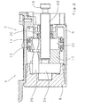
- Fig. 1 shows a switching device 2 for a here Gearbox unspecified.
- the switching device 2 has a shift cylinder 4, which is a shift cylinder sleeve 6 and a shift cylinder cover 8 are formed becomes.
- a shift rod 10 Within the shift cylinder 4 is on a shift rod 10 a switching piston 12 fastened with seals 14 and 16 is provided on the inner wall of the Slide the shift cylinder sleeve sealingly.
- a flange 18 is provided which Shift rod 10 with other components, not shown here the switching device 2 connects.
- Within the Shift cylinder sleeve 6 slides the shift rod 10 in one Seal 20, which is a first working chamber 22 opposite the Seals the environment.
- the first working chamber 22 is inside of the shift cylinder 4 between the seal 14 on Shift piston 12 and the seal 20 in the shift cylinder sleeve 6 formed.
- On the opposite side of the Shift piston 12 is between the shift cylinder cover 8th and the seal 16 on the switching piston 12 a second working chamber 24 formed.
- the switching piston 12 has two openings 28 and 30 through which the bolt 26 projects.
- the area of Switching piston 12 between the two openings 28 and 30 is exposed here and forms part of the working chamber 24.
- the outer diameter of the bolt 26 corresponds to the end position of the switching piston shown in FIG. 1 12 in this area 32 of the bolt 26 of the substantially the inner diameter of the openings 28 and 30, so that the bolt 26 and the openings 28 and 30 cooperate and form sealing points.
- the bolt 26 has a second region 34, in which the diameter of the bolt 26 de diameter in the range 32 corresponds.
- the opening acts in this area 34 30 of the switching piston 12 with the bolt 26 for formation a sealing point together when the switching piston 12 essentially the other end position in the switching cylinder 4th takes, as shown in Fig. 3.
- the bolt 26 has a third region 36 on, in which the diameter of the bolt 26 the Diameter in the areas 32 and 34 corresponds.
Landscapes
- Engineering & Computer Science (AREA)
- General Engineering & Computer Science (AREA)
- Mechanical Engineering (AREA)
- Physics & Mathematics (AREA)
- Fluid Mechanics (AREA)
- Gear-Shifting Mechanisms (AREA)
Abstract
Description
Es zeigen:
- Fig. 1
- den Schnitt durch eine Schalteinrichtung in einer Schaltstellung;
- Fig. 2
- den Schnitt durch die Schalteinrichtung in einer Synchronisationsphase und
- Fig. 3
- den Schnitt durch die Schalteinrichtung in einer zweiten Schaltstellung.
- 2
- Schalteinrichtung
- 4
- Schaltzylinder
- 6
- Schaltzylinderhülse
- 8
- Schaltzylinderdeckel
- 10
- Schaltstange
- 12
- Schaltkolben
- 14
- Dichtung
- 16
- Dichtung
- 18
- Flansch
- 20
- Dichtung
- 22
- Arbeitskammer
- 24
- Arbeitskammer
- 26
- Bolzen
- 28
- Öffnung
- 30
- Öffnung
- 32
- Bereich
- 34
- Bereich
- 36
- Bereich
Claims (7)
- Schalteinrichtung (2) für ein Kraftfahrzeug, die einen mit einem Druckmittel beaufschlagten Schaltzylinder (4) und einen im Schaltzylinder (4) befindlichen Schaltkolben (12) umfasst, der den Schaltzylinder (4) in zwei Arbeitskammern (22, 24) teilt und der eine Öffnung (30) aufweist, die dazu geeignet ist, einen Austausch von Druckmittel zwischen den beiden Arbeitskammern (22, 24) zuzulassen, dadurch gekennzeichnet, dass im Schaltzylinder (4) ein axial fixierter Bolzen (26) vorgesehen ist, der durch wenigstens die eine Öffnung (30) im Schaltkolben (12) hindurchragt und der einen Durchmesser aufweist, der auf der Länge des Bolzens (26) nicht konstant ist und der mit wenigstens der einen Öffnung (30) im Schaltkolben (12) zur Bildung von Dichtstellen zusammenwirkt.
- Schalteinrichtung (2) nach Anspruch 1, dadurch gekennzeichnet, dass der Bolzen (26) drei Bereiche (32, 34, 36) aufweist, in denen der Durchmesser derart ausgebildet ist, dass er mit wenigstens der einen Öffnung (30) im Schaltkolben (12) eine Dichtstelle bildet.
- Schalteinrichtung (2) nach Anspruch 2, dadurch gekennzeichnet, dass zwei (32, 34) der drei Bereiche (32, 34, 36) an Endstellungen des Schaltkolbens (12) vorliegen und dass der dritte Bereich (36) zwischen diesen beiden Bereichen (32, 34) liegt.
- Schalteinrichtung (2) nach Anspruch 2 oder 3, dadurch gekennzeichnet, dass der Durchmesser des Bolzens (26) von den beiden Bereichen (32, 34) an den Endstellungen des Schaltkolbens (12) her zum dritten Bereich (36) hin kontinuierlich abnimmt.
- Schalteinrichtung (2) nach Anspruch 1, dadurch gekennzeichnet, dass der Schaltkolben (12) zwei Öffnungen (28, 30) aufweist, durch die der Bolzen (26) hindurchragt.
- Schalteinrichtung (2) nach Anspruch 5, dadurch gekennzeichnet, dass jede der beiden Öffnungen (28, 30) im Schaltkolben (12) zur Bildung einer Dichtstelle jeweils entweder mit einem Bereich (32, 34) des Bolzens (26) an einer Endstellung des Schaltkolbens (12) oder dem dritten Bereich (36) zwischen den beiden Bereichen (32, 34) an den Endstellungen des Schaltkolbens zusammenwirkt.
- Schalteinrichtung (2) nach einem der Ansprüche 1 bis 6, dadurch gekennzeichnet, dass sich eine Öffnung (28, 30) im Schaltkolben (12) im dritten Bereich (36) des Bolzen (12) befindet, wenn sich die Schalteinrichtung (2) in einer Synchronisationsphase befindet.
Applications Claiming Priority (2)
| Application Number | Priority Date | Filing Date | Title |
|---|---|---|---|
| DE10321280A DE10321280A1 (de) | 2003-05-13 | 2003-05-13 | Schalteinrichtung |
| DE10321280 | 2003-05-13 |
Publications (3)
| Publication Number | Publication Date |
|---|---|
| EP1477711A2 true EP1477711A2 (de) | 2004-11-17 |
| EP1477711A3 EP1477711A3 (de) | 2006-06-07 |
| EP1477711B1 EP1477711B1 (de) | 2009-07-22 |
Family
ID=33016344
Family Applications (1)
| Application Number | Title | Priority Date | Filing Date |
|---|---|---|---|
| EP04010995A Expired - Lifetime EP1477711B1 (de) | 2003-05-13 | 2004-05-08 | Schalteinrichtung |
Country Status (3)
| Country | Link |
|---|---|
| US (1) | US7083034B2 (de) |
| EP (1) | EP1477711B1 (de) |
| DE (2) | DE10321280A1 (de) |
Cited By (1)
| Publication number | Priority date | Publication date | Assignee | Title |
|---|---|---|---|---|
| EP1873425A1 (de) * | 2006-06-29 | 2008-01-02 | FTE automotive GmbH | Hydraulische Stellvorrichtung für die Betätigung einer Schaltstange insbesondere eines Schaltgetriebes für Kraftfahrzeuge |
Families Citing this family (3)
| Publication number | Priority date | Publication date | Assignee | Title |
|---|---|---|---|---|
| DE102014226022A1 (de) * | 2014-12-16 | 2016-06-16 | Zf Friedrichshafen Ag | Hydraulische Betätigungsvorrichtung für ein formschlüssiges Schaltelement eines Getriebes |
| CN106224402B (zh) * | 2016-09-08 | 2018-06-15 | 北京精密机电控制设备研究所 | 一种一体化插销式离合器 |
| DE102017011895A1 (de) * | 2017-12-21 | 2019-06-27 | Wabco Gmbh | Kolben-Zylinder-Anordnung |
Citations (1)
| Publication number | Priority date | Publication date | Assignee | Title |
|---|---|---|---|---|
| FR1361134A (fr) | 1963-06-25 | 1964-05-15 | Bbc Brown Boveri & Cie | Système de commande pneumatique à amortissement par air |
Family Cites Families (9)
| Publication number | Priority date | Publication date | Assignee | Title |
|---|---|---|---|---|
| FR2006183A1 (de) * | 1968-04-13 | 1969-12-19 | Daimler Benz Ag | |
| DE2151194A1 (de) | 1971-10-14 | 1973-04-19 | Cascade Corp | Entlastungsventil |
| US3896703A (en) * | 1974-06-24 | 1975-07-29 | Powersteering Trust Reg | Arrangement for relieving the mechanical stresses in power assisted steering for vehicles in the full-lock steering positions |
| ES8205163A1 (es) * | 1981-08-04 | 1982-06-16 | Bendiberica Sa | Perfeccionamientos en distribuidores fluidodinamicos |
| JPH055297Y2 (de) * | 1988-12-15 | 1993-02-12 | ||
| DE19543646A1 (de) | 1995-11-23 | 1997-05-28 | Zahnradfabrik Friedrichshafen | Schalteinrichtung |
| DE19604516B4 (de) | 1996-02-08 | 2007-03-01 | Zf Friedrichshafen Ag | Pneumatische Schalteinrichtung |
| GB2354288B (en) * | 1999-09-15 | 2003-12-17 | Automotive Prod France | Hydraulic damper |
| DE20214904U1 (de) * | 2002-09-26 | 2003-02-13 | TRW Occupant Restraint Systems GmbH & Co. KG, 73553 Alfdorf | Vorrichtung zum Anheben einer Motorhaube eines Fahrzeugs |
-
2003
- 2003-05-13 DE DE10321280A patent/DE10321280A1/de not_active Withdrawn
-
2004
- 2004-05-07 US US10/841,899 patent/US7083034B2/en not_active Expired - Fee Related
- 2004-05-08 EP EP04010995A patent/EP1477711B1/de not_active Expired - Lifetime
- 2004-05-08 DE DE502004009775T patent/DE502004009775D1/de not_active Expired - Fee Related
Patent Citations (1)
| Publication number | Priority date | Publication date | Assignee | Title |
|---|---|---|---|---|
| FR1361134A (fr) | 1963-06-25 | 1964-05-15 | Bbc Brown Boveri & Cie | Système de commande pneumatique à amortissement par air |
Cited By (1)
| Publication number | Priority date | Publication date | Assignee | Title |
|---|---|---|---|---|
| EP1873425A1 (de) * | 2006-06-29 | 2008-01-02 | FTE automotive GmbH | Hydraulische Stellvorrichtung für die Betätigung einer Schaltstange insbesondere eines Schaltgetriebes für Kraftfahrzeuge |
Also Published As
| Publication number | Publication date |
|---|---|
| US20040226799A1 (en) | 2004-11-18 |
| EP1477711B1 (de) | 2009-07-22 |
| DE502004009775D1 (de) | 2009-09-03 |
| DE10321280A1 (de) | 2004-12-23 |
| EP1477711A3 (de) | 2006-06-07 |
| US7083034B2 (en) | 2006-08-01 |
Similar Documents
| Publication | Publication Date | Title |
|---|---|---|
| DE3413866C2 (de) | Hydrostatisches Antriebssystem | |
| DE102009014502B4 (de) | Hydraulischer Aktor für Getriebe mit verringertem Geräusch | |
| DE19721036B4 (de) | Steuerventil für ein Fahrzeug mit einer Druckmittelanlage | |
| DE10325202A1 (de) | Druckabhängiges Sperrventil und Hydrauliksystem mit einem solchen | |
| EP0180583B1 (de) | Druckmittelbetätigte schalteinrichtung | |
| EP1348828A2 (de) | Dämpfungsvorrichtung für bewegliche Möbelteile | |
| DE102014216580A1 (de) | Hydraulische Steuerungsvorrichtung für ein Automatikgetriebe | |
| DE102015109474A1 (de) | Umschaltventil und Pleuel mit einem Umschaltventil | |
| DE2843592C3 (de) | Hilfskraftlenkgetriebe | |
| EP1219854B1 (de) | Dämpf- und Bremsvorrichtung für Möbelteile | |
| EP1477711B1 (de) | Schalteinrichtung | |
| EP0837250B1 (de) | Druckmittelbetätigbarer Arbeitszylinder | |
| DE102004015811B4 (de) | Stufenlos blockierbare Verstelleinrichtung | |
| EP1428962B1 (de) | Kolben-Zylinder-Einheit | |
| DE69601157T2 (de) | Druckreduzierventil | |
| DE102009029038A1 (de) | Verfahren zur Synchronisierung, Stellmotor und Schalteinrichtung mit Stellmotor | |
| DE102006022551B3 (de) | Hauptbremszylinder | |
| EP0684391B1 (de) | Druckmittelbetätigbarer Arbeitszylinder | |
| DE3710080C1 (de) | Selbsttaetige Schaltvorrichtung eines Planetenraeder-Gangwechselgetriebes mit Mitteln zum Sperren des Einrueckens einer Rueckwaerts-Kupplung und/oder -Bremse | |
| DE19636399A1 (de) | Druckzylinder mit einer verschiebbaren Zwischenkammer | |
| EP2085634B1 (de) | Hydraulisches Betätigungssystem für eine Kraftfahrzeugkupplung mit zwei Druckleitungen | |
| DE102005030403B4 (de) | Verstellelement | |
| EP3085921A1 (de) | Umschaltventil und pleuel mit einem umschaltventil | |
| DE102020203132A1 (de) | Ventilanordnung für ein hydraulisches Steuergerät eines Getriebes eines Kraftfahrzeugs | |
| EP4145022A1 (de) | Dreistellungsschaltmodul |
Legal Events
| Date | Code | Title | Description |
|---|---|---|---|
| PUAI | Public reference made under article 153(3) epc to a published international application that has entered the european phase |
Free format text: ORIGINAL CODE: 0009012 |
|
| AK | Designated contracting states |
Kind code of ref document: A2 Designated state(s): AT BE BG CH CY CZ DE DK EE ES FI FR GB GR HU IE IT LI LU MC NL PL PT RO SE SI SK TR |
|
| AX | Request for extension of the european patent |
Extension state: AL HR LT LV MK |
|
| PUAL | Search report despatched |
Free format text: ORIGINAL CODE: 0009013 |
|
| AK | Designated contracting states |
Kind code of ref document: A3 Designated state(s): AT BE BG CH CY CZ DE DK EE ES FI FR GB GR HU IE IT LI LU MC NL PL PT RO SE SI SK TR |
|
| AX | Request for extension of the european patent |
Extension state: AL HR LT LV MK |
|
| 17P | Request for examination filed |
Effective date: 20060513 |
|
| AKX | Designation fees paid |
Designated state(s): DE SE |
|
| 17Q | First examination report despatched |
Effective date: 20071029 |
|
| GRAP | Despatch of communication of intention to grant a patent |
Free format text: ORIGINAL CODE: EPIDOSNIGR1 |
|
| GRAS | Grant fee paid |
Free format text: ORIGINAL CODE: EPIDOSNIGR3 |
|
| GRAA | (expected) grant |
Free format text: ORIGINAL CODE: 0009210 |
|
| AK | Designated contracting states |
Kind code of ref document: B1 Designated state(s): DE SE |
|
| REF | Corresponds to: |
Ref document number: 502004009775 Country of ref document: DE Date of ref document: 20090903 Kind code of ref document: P |
|
| REG | Reference to a national code |
Ref country code: SE Ref legal event code: TRGR |
|
| PLBE | No opposition filed within time limit |
Free format text: ORIGINAL CODE: 0009261 |
|
| STAA | Information on the status of an ep patent application or granted ep patent |
Free format text: STATUS: NO OPPOSITION FILED WITHIN TIME LIMIT |
|
| 26N | No opposition filed |
Effective date: 20100423 |
|
| EUG | Se: european patent has lapsed | ||
| PG25 | Lapsed in a contracting state [announced via postgrant information from national office to epo] |
Ref country code: SE Free format text: LAPSE BECAUSE OF NON-PAYMENT OF DUE FEES Effective date: 20100509 |
|
| PG25 | Lapsed in a contracting state [announced via postgrant information from national office to epo] |
Ref country code: DE Free format text: LAPSE BECAUSE OF NON-PAYMENT OF DUE FEES Effective date: 20101201 |