EP1477647A1 - Outboard motor - Google Patents
Outboard motor Download PDFInfo
- Publication number
- EP1477647A1 EP1477647A1 EP04291201A EP04291201A EP1477647A1 EP 1477647 A1 EP1477647 A1 EP 1477647A1 EP 04291201 A EP04291201 A EP 04291201A EP 04291201 A EP04291201 A EP 04291201A EP 1477647 A1 EP1477647 A1 EP 1477647A1
- Authority
- EP
- European Patent Office
- Prior art keywords
- cover
- introduction
- cable
- engine
- sealing member
- Prior art date
- Legal status (The legal status is an assumption and is not a legal conclusion. Google has not performed a legal analysis and makes no representation as to the accuracy of the status listed.)
- Granted
Links
Images


Classifications
-
- B—PERFORMING OPERATIONS; TRANSPORTING
- B63—SHIPS OR OTHER WATERBORNE VESSELS; RELATED EQUIPMENT
- B63H—MARINE PROPULSION OR STEERING
- B63H20/00—Outboard propulsion units, e.g. outboard motors or Z-drives; Arrangements thereof on vessels
- B63H20/32—Housings
-
- F—MECHANICAL ENGINEERING; LIGHTING; HEATING; WEAPONS; BLASTING
- F02—COMBUSTION ENGINES; HOT-GAS OR COMBUSTION-PRODUCT ENGINE PLANTS
- F02B—INTERNAL-COMBUSTION PISTON ENGINES; COMBUSTION ENGINES IN GENERAL
- F02B61/00—Adaptations of engines for driving vehicles or for driving propellers; Combinations of engines with gearing
- F02B61/04—Adaptations of engines for driving vehicles or for driving propellers; Combinations of engines with gearing for driving propellers
- F02B61/045—Adaptations of engines for driving vehicles or for driving propellers; Combinations of engines with gearing for driving propellers for outboard marine engines
-
- F—MECHANICAL ENGINEERING; LIGHTING; HEATING; WEAPONS; BLASTING
- F02—COMBUSTION ENGINES; HOT-GAS OR COMBUSTION-PRODUCT ENGINE PLANTS
- F02B—INTERNAL-COMBUSTION PISTON ENGINES; COMBUSTION ENGINES IN GENERAL
- F02B75/00—Other engines
- F02B75/16—Engines characterised by number of cylinders, e.g. single-cylinder engines
- F02B75/18—Multi-cylinder engines
- F02B75/20—Multi-cylinder engines with cylinders all in one line
-
- F—MECHANICAL ENGINEERING; LIGHTING; HEATING; WEAPONS; BLASTING
- F02—COMBUSTION ENGINES; HOT-GAS OR COMBUSTION-PRODUCT ENGINE PLANTS
- F02B—INTERNAL-COMBUSTION PISTON ENGINES; COMBUSTION ENGINES IN GENERAL
- F02B75/00—Other engines
- F02B75/02—Engines characterised by their cycles, e.g. six-stroke
- F02B2075/022—Engines characterised by their cycles, e.g. six-stroke having less than six strokes per cycle
- F02B2075/027—Engines characterised by their cycles, e.g. six-stroke having less than six strokes per cycle four
-
- F—MECHANICAL ENGINEERING; LIGHTING; HEATING; WEAPONS; BLASTING
- F02—COMBUSTION ENGINES; HOT-GAS OR COMBUSTION-PRODUCT ENGINE PLANTS
- F02B—INTERNAL-COMBUSTION PISTON ENGINES; COMBUSTION ENGINES IN GENERAL
- F02B75/00—Other engines
- F02B75/16—Engines characterised by number of cylinders, e.g. single-cylinder engines
- F02B75/18—Multi-cylinder engines
- F02B2075/1804—Number of cylinders
- F02B2075/1816—Number of cylinders four
-
- F—MECHANICAL ENGINEERING; LIGHTING; HEATING; WEAPONS; BLASTING
- F02—COMBUSTION ENGINES; HOT-GAS OR COMBUSTION-PRODUCT ENGINE PLANTS
- F02B—INTERNAL-COMBUSTION PISTON ENGINES; COMBUSTION ENGINES IN GENERAL
- F02B2275/00—Other engines, components or details, not provided for in other groups of this subclass
- F02B2275/18—DOHC [Double overhead camshaft]
Definitions
- the present invention relates to outboard motors, and more particularly, to a cover structure for introducing cables into an engine compartment.
- a cover constituting the appearance of an outboard motor is generally made from an aluminum alloy to provide required rigidity to the outboard motor to be supported on a stern of a boat.
- a cover made from a resin material is in practical use to reduce weight and cost.
- an engine cover forming an upper half of an engine compartment and an under cover forming a lower half of the engine compartment are made from resin.
- cables including an engine control cable for opening and closing a throttle valve, a power train control cable for switching between forward and rearward propulsion, a power supply cable, a various electrical signal transmission cable and a fuel feeding pipe are introduced.
- An introduction portion for the cables is provided in the cover body.
- a sealing member is provided around the introduction portion and the cables to prevent ingress of water into the engine compartment.
- An under cover of the outboard motor is divided into left and right portions.
- a right cover of the left and right divisions is formed with a horizontally notched portion in a substantially U shape.
- a front cover joined to the right cover is formed with a horizontally extending protruded portion fitted into the notched portion.
- a circular retention opening is formed between the deepest portion of the notched portion and the distal end of the protruded portion.
- a cable holding member made from an elastic material such as rubber is fitted into the retention opening. That is, the cable holding member is held between the notched portion and the protruded portion in a sandwiched manner. Cables are inserted through the cable holding member and retained therein.
- a watertight groove is formed around the periphery of the cable holding member.
- a flange formed around the inner periphery of the retention opening is fitted into the watertight groove, thereby forming a sealing structure.
- an outboard motor which comprises: an engine; a cover constituting at least a part of an engine compartment housing the engine; a cable introduction cover mounted to the cover, the cable introduction cover having an introduction opening through which cables including cables and pipes to be introduced into the engine compartment are inserted; and a sealing member axially held in the introduction opening of the cable introduction cover to seal and retain the cables.
- the cable introduction cover is mounted to the cover, and the introduction opening which preferably opens in a fore-and-aft direction is formed in the cable introduction cover, and the sealing member for retaining the cables is inserted into the introduction opening from a fore-and-aft direction to be held therein, so that the sealing member is sealed and retained circumferentially between the cable introduction cover and the sealing member.
- a sealing surface continues smoothly, facilitating the provision of good sealing performance, and also resulting in good productivity.
- the sealing member can be easily aligned with the cable introduction cover, so that the sealing member can be retained under a generally uniform pressure.
- the cover is preferably divided into left and right portions;
- the cable introduction cover preferably has a cover body joined to the split cover and a partly tubular introduction opening provided to the cover body, opening in a forward direction of the outboard motor;
- the sealing member preferably has, around a periphery thereof, a circular flexible engaging portion engaging and sealing an inner peripheral surface of the introduction opening. Consequently, the cables can be inserted and fitted into the introduction opening of the cable introduction cover, and the flexible engaging portion can provide sealing, eliminating the need to firmly press the entire sealing member.
- the inner peripheral surface of the tubular introduction opening of the cable introduction cover has an inclined surface with a diameter reduced in a forward direction
- the circular flexible engaging portion around the periphery of the sealing member constitutes a lip, a distal end portion of the lip being bent correspondingly to the inclined surface of the introduction opening for close contact, forming a seal between the periphery of the sealing member and the inner peripheral surface of the introduction opening.
- the outboard motor 1 shown in FIG. 1 includes a mount case 4 supporting an engine 2, and an engine cover 9 covering the engine 2 and defining an engine compartment 18.
- the engine 2 is a vertical engine with a crankshaft 2a oriented vertically.
- the engine 2 is a multicylinder engine having a cylinder block 2d disposed in a fore and aft intermediate position in the outboard motor 1, in which multiple cylinders 2b (four cylinders in the embodiment) are arranged above and below in parallel.
- Pistons 2c are provided in the cylinders 2b, respectively.
- the centerline of each cylinder 2b is oriented in a fore-and-aft direction of the outboard motor 1.
- a cylinder head 2e is provided at the rear of the cylinder block 2d.
- a cylinder head cover 2f is provided at the rear of the cylinder head 2e.
- a crankcase 2g is disposed at the front of the cylinder block 2d.
- the cylinder block 2d, cylinder head 2e, cylinder head cover 2f and crankcase 2g constitute an engine assembly.
- the engine assembly is supported by the mount case 4 on an oil case 5.
- An oil pump body is provided below the engine 2.
- Combustion chambers 2h of the engine 2 are formed by the cylinders 2b, pistons 2c and cylinder head 2e.
- the combustion chambers 2h communicate with exhaust ports 2i provided in the cylinder head 2e, respectively.
- An exhaust manifold 3 is provided vertically, laterally outside the cylinder head 2e so as to correspond to the exhaust ports 2i.
- the oil case 5 has an oil pan 5c and an exhaust chamber 17a to be described below.
- An oil suction pipe 5a and an oil strainer 5b are housed in the oil pan 5c.
- the mount case 4 serves as a partition between the engine compartment 18 and a chamber 17 located below.
- crankshaft 2a is located in a forward portion of the outboard motor 1 on the right in FIG. 1.
- a lower end portion of the crankshaft 2a is connected to an output shaft 2j via a flywheel not shown.
- the output shaft 2j vertically passes through the mount case 4 and is connected to an upper end portion of a drive shaft 6 coaxial with the output shaft 2j.
- the drive shaft 6 extends vertically downward through and between the oil pan 5c and the oil case 5 to be out to rotationally drive an output shaft 8a via a transmission mechanism 7.
- a propeller 8 is connected to a rear end portion of the output shaft 8a.
- the drive shaft 6 driven by the engine 2 rotates the propeller 8 via the transmission mechanism 7.
- a hull is propelled by the rotation of the propeller 8.
- the engine cover 9 is made from a resin material and surrounds upper and peripheral portions of the engine 2. That is, the engine cover 9 covers a portion of the engine 2 above a vertically intermediate portion thereof.
- a resin under cover 10 provided below the engine cover 9 covers a lower half portion of the engine 2 and the periphery of the mount case 4 housing the oil pump body.
- An extension case 11 is connected to a lower portion of the oil case 5 to extend downward.
- the extension case 11 is formed from an aluminum alloy.
- a gearbox 12 containing the transmission mechanism 7 is integrally provided to a lower portion of the extension case 11.
- the gearbox 12 is formed from an aluminum alloy.
- the under cover 10 covers mating surfaces of the oil case 5 and the extension case 11.
- the mount case 4 and surrounding portions are formed from metal such as an aluminum alloy.
- a swivel shaft 13a is provided vertically between a front portion of the mount case 4 and a front portion of the extension case 11.
- the swivel shaft 13a is housed in a swivel case 13.
- a tilt shaft 14a supporting the outboard motor 1 in a vertically rotatable manner is provided at a stern bracket 14 connected to the swivel case 13.
- the stern bracket 14 is fixed to a stern.
- the outboard motor 1 is thus supported in a steerable and tiltable manner with respect to the stern.
- An exhaust outlet 3a of the exhaust manifold 3 communicates with an exhaust pipe 16 integrally formed with the oil case 5 via a communicating opening 15 provided in the mount case 4.
- An exhaust passage is formed by the exhaust manifold 3, communicating opening 15 and exhaust pipe 16.
- the exhaust pipe 16 is located within the exhaust chamber 17a, extending downward adjacently to the rear of the oil pan 5c.
- a passage 19 communicating with the exhaust chamber 17a is provided in a rear portion 4a of the mount case 4.
- a proximal end portion of an exhaust outlet pipe 20 is connected to the passage 19 at the opposite side to the side of the exhaust chamber 17a.
- a distal end portion 20a of the exhaust outlet pipe 20 leads to the outside through an opening 10q formed in the under cover 10. That is, outside air and the exhaust chamber 17a communicate with one another through the passage 19 and the exhaust outlet pipe 20.
- the engine cover 9 has a roof 9a formed with an air inlet opening 30 for taking air into the engine compartment 18.
- the air inlet opening 30 includes a first air inlet opening 30a formed in a rear portion of the roof 9a, a second air inlet opening 30b formed in a longitudinally middle portion of the roof 9a, and a louvered third air inlet opening 30c formed forward of the second air inlet opening 30b.
- Air taken in through the air inlet openings 30, 30a, 30b and 30c is guided into the engine compartment 18 via an intake passage unit 21.
- the intake passage unit 21 includes a connecting portion 22, and left and right two intake passage portions 23, 24 integrally formed at the left and the right of the connecting portion 22, extending downward with their lower ends located within the engine compartment 18 (FIG. 1 shows a cross section and the right intake passage portion 24 is not shown), having an inverted U shape.
- the left and right intake passage portions 23, 24 are located along the opposite sides of the rear of the engine 2. Air introduced through the air inlet opening 30 is guided into the engine compartment 18 through the left and right intake passage portions 23, 24 which communicate with openings formed at the left and the right of the connecting portion 22.
- FIG. 2 shows an engine in horizontal cross section with the engine cover removed.
- the engine 2 is of a vertical type with the crankshaft 2a oriented vertically and the cylinder axis oriented horizontally.
- the under cover 10 is made from resin and is configured with left and right split cover halves 10L, 10R joined together.
- a sealing lid 40 is attached to a rear mating surface of the joined cover halves 10L, 10R.
- a cable holder 41 is provided between front portions of the joined left and right cover halves 10L, 10R.
- a cable introduction cover 50 is joined to a front portion of the cover right half 10R.
- FIG. 3 illustrates the mount case 4, under cover 10, cable holder 41 and cable introduction cover 50.
- the left and right halves 10L, 10R of the under cover 10 are comprised of upper half portions 10a, 10a, and lower half portions 10b, 10b, respectively.
- the upper half portions 10a, 10a are fore and aft elongated and expanded outward.
- the lower half portions 10b, 10b have a shorter fore-and-aft length and have a downwardly narrowed shape.
- the upper half portions 10a, 10a each have reinforcing horizontal ribs 10c, 10d attached to the inner surface by oscillation welding, ultrasonic welding, riveting or the like, in such a manner as to fore and aft extend, being spaced vertically.
- a plurality of vertical reinforcing ribs 10e spaced fore and aft is likewise provided between the upper and lower reinforcing ribs 10c, 10d.
- the left and right cover halves 10L, 10R are provided with connected portions 10f at their mating portions.
- the connected portions 10f are butted and bolted together.
- Rib-like standing portions 10g, 10g to engage a lower edge portion of the engine cover 9 are provided along upper edge portions of the left and right cover halves 10L, 10R.
- a sealing member 4a such as rubber having elasticity is fitted onto the periphery of the mount case 4.
- the mount case 4 is fitted between the lower reinforcing ribs 10d, 10d via the sealing member 4a.
- Reference sign 4b denotes a support hole for supporting an upper end portion of the swivel shaft 13a shown in FIG. 1, and 4c denotes an insertion hole for the output shaft 2j.
- Reference numeral 15 denotes the communicating opening for connecting the exhaust outlet 3a of the exhaust manifold 3 to the exhaust pipe 16.
- the cable holder 41 made from an aluminum alloy is extended between front upper portions of the left and right cover halves 10L, 10R to connect them.
- the cable holder 41 has a holder body 42.
- the holder body 42 integrally has a standing portion 42a formed at its upper edge portion, connected portions 42b, 42c formed at the left and the right of the upper edge portion, and connected portions 42d, 42e formed at the left and the right of its lower portion.
- the cable holder 41 is fixed to the engine assembly or to the mount case 4 via the connected portions 42d, 42e.
- the holder body 42 integrally has an arm 43 extended laterally outward from a right side portion.
- the arm 43 has in it upper portion a support depression 43a formed in a semicircular shape, and has at its right end portion a mounted portion 43b formed upward.
- the right cover half 10R has a connected portion 10i formed at its front upper portion, and a platform portion 10j extending from its front portion forward and inward.
- a notch 10h forming a substantially L shape with the platform portion 10j in front and side views is formed in a front portion of the right cover half 10R.
- the platform portion 10j has two connected portions 10k, 10m formed at its upper edge portions and a connected portion 10n formed at its lower edge portion.
- the left cover half 10L has a connected portion 10p formed at its front end portion.
- the cable introduction cover 50 has at its upper edge portion a standing portion 51a corresponding to the standing portion 10g of the right cover half 10R and the standing portion 42a of the cable holder 41.
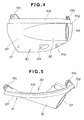
- the structure of the cable introduction cover 50 is shown in detail in FIGS. 4 and 5.
- the cable introduction cover 50 has a cover body 51.
- the cover body 51 has a side portion 51f and a front portion 51g.
- the cover body 51 is, as shown in FIG. 5, curved in a plan view, having a connected portion 51c formed at its rear upper portion, and a connected portion 51b formed at the inside of its front end portion.
- the cover body 51 also has two connected portions 51d, 51e having through holes opening forward in its lower forward portion.
- the cable introduction cover 50 has a tubular portion 52 expanded outside of the cover body 51 from a fore-and-aft intermediate portion to a front portion, having a forward opening 53.
- FIGS. 6, 7 and 8 illustrate the structure of mounting the cable introduction cover 50 and a sealing member 55 to the under cover 10.
- the cable introduction cover 50 is fitted onto the notch 10h formed in the front portion of the right cover half 10R as shown in FIG. 8, with the connected portions 10i, 10k, 10m of the right cover half 10R connected to the connected portions 51c, 51d, 51e of the cable introduction cover 50 with bolts 60, respectively.
- the cable introduction cover 50 constitutes a part of a right front portion of the right cover half 10R.
- the cable holder 41 is interposed between the upper portions of the left and right cover halves 10L, 10R as shown in FIG. 8.
- the connected portions 42c, 42b at upper left and right portions of the cable holder 41 are connected to the connected portion 51b of the cable introduction cover 50 and the connected portion 10p of the left cover half 10L with bolts 60, respectively.
- the connected portions 42d, 42e at lower left and right portions of the cable holder 41 are connected to the connected portion 10n extending downward below the platform portion 10j of the right cover half 10R and another portion with bolts 60. In this manner, the cable holder 41 is mounted to the left and right cover halves 10L, 10R.
- Cables 56 introduced into the engine compartment 18 include an engine control cable for opening and closing a throttle valve, a powertrain control cable for switching between forward and rearward propulsion, a power supply cable, a various electrical signal transmission cable and a fuel feeding pipe.
- the cables 56 are inserted through a plurality of through holes 55d formed in and through the rubber sealing member 55 in a fore-and-aft direction, to be held in the sealing member 55 in a sealed state.
- the sealing member 55 is a cylinder having the through holes 55b in an axial direction, having circular sealing protrusions (flexible engaging portions) 55a around its periphery.
- reference sign C denotes a center line of an introduction opening 53 into which the sealing member 55 is fitted.
- the tubular portion 52 of the cable introduction cover 50 has, at the introduction opening 53, a double-pipe structure of a fore and aft short length in which a distal end portion of the tubular portion 52 is bent inward.
- An inner peripheral surface of the introduction opening 53 is formed with an inclined surface 53, having a smaller inside diameter in a forward direction of the outboard motor and having a larger inside diameter in a rearward direction.
- the sealing member 55 has the circular lips 55a constituting flexible sealing portions around its periphery, and has a circular collar 55c at its rearward portion. A front surface of the circular color 55c abuts on a rear end 53b of the introduction opening 53.
- Distal end portions 55b of the lips 55a are bent to closely contact the inclined surface 53a of the introduction opening 53 as shown in FIG. 7, providing high sealing performance.
- the sealing member 55 is fitted into the introduction opening 53 of the cable introduction cover 50, and the cables 56 and pipes are inserted through the through holes 55b in the sealing member 55.
- the sealing member 55 is supported by the semicircular support depression 43a formed in the arm 43 of the cable holder 41 fixed in advance to the engine 2, and the cables 56 are fixed to the cable holder 41 by a keep plate 44.
- the cable introduction cover 50 is placed from the front and fastened in a given manner, providing a first seal between the inner peripheral surface of the inclined surface 53a of the cable introduction cover 50 and the lips 55a, and a second seal by abutment between the rear end 53b of the introduction opening 53 and the collar 55c of the sealing member 55. High sealing performance can thus be easily obtained.
- a lower half portion of a rear half portion of the sealing member 55 is supported on the support depression 43a formed in the arm 43 of the cable holder 41, and the keep plate 44 (see also FIG. 3) is connected to the connected portion 43b at the distal end portion of the arm 43, thereby to secure the retention of the sealing member 55.
Abstract
Description
Claims (3)
- An outboard motor, comprising:an engine (2);a cover constituting at least a part of an engine compartment (18) housing the engine;a cable introduction cover (50) mounted to the cover, the cable introduction cover having an introduction opening (53) through which cables (56) including cables and pipes to be introduced into the engine compartment are inserted; anda sealing member (55) axially held in the introduction opening of the cable introduction cover to seal and retain the cables.
- The outboard motor of claim 1, wherein the cover (10) is divided into left and right portions, the cable introduction cover (50) has a cover body (51) joined to the split cover, and a partly tubular introduction opening (53) provided to the cover body, opening in a forward direction of the outboard motor (1), and the sealing member (55) has, around a periphery thereof, a circular flexible engaging portion (55a) engaging and sealing an inner peripheral surface of the introduction opening.
- The outboard motor of claim 2, wherein the inner peripheral surface of the tubular introduction opening (53) of the cable introduction cover (50) has an inclined surface (53a) with a diameter reduced in a forward direction, and the circular flexible engaging portion around the periphery of the sealing member constitutes a lip (55a), a distal end portion of the lip being bent correspondingly to the inclined surface (53a) of the introduction opening for close contact, forming a seal between the periphery of the sealing member and the inner peripheral surface of the introduction opening.
Applications Claiming Priority (2)
| Application Number | Priority Date | Filing Date | Title |
|---|---|---|---|
| JP2003135083A JP4244157B2 (en) | 2003-05-13 | 2003-05-13 | Cover structure of outboard motor |
| JP2003135083 | 2003-05-13 |
Publications (2)
| Publication Number | Publication Date |
|---|---|
| EP1477647A1 true EP1477647A1 (en) | 2004-11-17 |
| EP1477647B1 EP1477647B1 (en) | 2009-01-07 |
Family
ID=33028351
Family Applications (1)
| Application Number | Title | Priority Date | Filing Date |
|---|---|---|---|
| EP04291201A Expired - Fee Related EP1477647B1 (en) | 2003-05-13 | 2004-05-11 | Outboard motor |
Country Status (5)
| Country | Link |
|---|---|
| US (1) | US6923695B2 (en) |
| EP (1) | EP1477647B1 (en) |
| JP (1) | JP4244157B2 (en) |
| CN (1) | CN1286699C (en) |
| ES (1) | ES2320219T3 (en) |
Families Citing this family (7)
| Publication number | Priority date | Publication date | Assignee | Title |
|---|---|---|---|---|
| JP4719615B2 (en) * | 2006-05-01 | 2011-07-06 | 本田技研工業株式会社 | Cover structure of outboard motor. |
| JP5019902B2 (en) * | 2007-02-09 | 2012-09-05 | ヤマハ発動機株式会社 | Cable mounting structure for ship propulsion devices |
| DE102007048056A1 (en) * | 2007-10-05 | 2009-04-09 | Zf Friedrichshafen Ag | Implementation device for electrical and hydraulic lines on a watercraft |
| JP5134992B2 (en) * | 2008-02-01 | 2013-01-30 | 本田技研工業株式会社 | Outboard motor |
| JP5192923B2 (en) * | 2008-06-24 | 2013-05-08 | ヤマハ発動機株式会社 | Outboard cowl structure |
| US8858280B1 (en) | 2010-10-29 | 2014-10-14 | Brp Us Inc. | Marine engine rigging system |
| US8834216B1 (en) | 2013-01-31 | 2014-09-16 | Brp Us Inc. | Water deflector for a marine outboard engine |
Citations (6)
| Publication number | Priority date | Publication date | Assignee | Title |
|---|---|---|---|---|
| GB1389297A (en) * | 1972-04-24 | 1975-04-03 | Teleflex Ltd | Seals |
| US4046481A (en) * | 1976-11-22 | 1977-09-06 | Detroit Marine Engineering Corporation | Gland nut retaining means |
| JPS55119593A (en) * | 1979-03-06 | 1980-09-13 | Yamaha Motor Co Ltd | Seal mechanism for engine cover in outboard engine |
| US5637021A (en) | 1994-07-19 | 1997-06-10 | Sanshin Kogyo Kabushiki Kaisha | Control for outboard motor |
| US6183322B1 (en) * | 1998-08-25 | 2001-02-06 | Suzuki Kabushiki Kaisha | Operation cable mounting structure of outboard motor |
| JP2001039390A (en) | 1999-07-30 | 2001-02-13 | Suzuki Motor Corp | Split engine cover structure for outboard engine |
Family Cites Families (2)
| Publication number | Priority date | Publication date | Assignee | Title |
|---|---|---|---|---|
| US4533331A (en) * | 1982-01-11 | 1985-08-06 | Outboard Marine Corporation | Vent and drain assembly for marine propulsion device |
| US4969847A (en) * | 1989-07-31 | 1990-11-13 | Brunswick Corporation | Through-cowl strain relief assembly for outboard motor |
-
2003
- 2003-05-13 JP JP2003135083A patent/JP4244157B2/en not_active Expired - Fee Related
-
2004
- 2004-05-05 US US10/839,510 patent/US6923695B2/en active Active
- 2004-05-11 EP EP04291201A patent/EP1477647B1/en not_active Expired - Fee Related
- 2004-05-11 ES ES04291201T patent/ES2320219T3/en active Active
- 2004-05-12 CN CN200410034785.0A patent/CN1286699C/en not_active Expired - Fee Related
Patent Citations (6)
| Publication number | Priority date | Publication date | Assignee | Title |
|---|---|---|---|---|
| GB1389297A (en) * | 1972-04-24 | 1975-04-03 | Teleflex Ltd | Seals |
| US4046481A (en) * | 1976-11-22 | 1977-09-06 | Detroit Marine Engineering Corporation | Gland nut retaining means |
| JPS55119593A (en) * | 1979-03-06 | 1980-09-13 | Yamaha Motor Co Ltd | Seal mechanism for engine cover in outboard engine |
| US5637021A (en) | 1994-07-19 | 1997-06-10 | Sanshin Kogyo Kabushiki Kaisha | Control for outboard motor |
| US6183322B1 (en) * | 1998-08-25 | 2001-02-06 | Suzuki Kabushiki Kaisha | Operation cable mounting structure of outboard motor |
| JP2001039390A (en) | 1999-07-30 | 2001-02-13 | Suzuki Motor Corp | Split engine cover structure for outboard engine |
Non-Patent Citations (1)
| Title |
|---|
| PATENT ABSTRACTS OF JAPAN vol. 004, no. 169 (M - 043) 21 November 1980 (1980-11-21) * |
Also Published As
| Publication number | Publication date |
|---|---|
| CN1550411A (en) | 2004-12-01 |
| US20040226737A1 (en) | 2004-11-18 |
| US6923695B2 (en) | 2005-08-02 |
| JP2004338464A (en) | 2004-12-02 |
| EP1477647B1 (en) | 2009-01-07 |
| JP4244157B2 (en) | 2009-03-25 |
| CN1286699C (en) | 2006-11-29 |
| ES2320219T3 (en) | 2009-05-20 |
Similar Documents
| Publication | Publication Date | Title |
|---|---|---|
| US7210562B2 (en) | Oil pan structure for four-cycle engine | |
| EP1477647B1 (en) | Outboard motor | |
| US7238069B2 (en) | Outboard motor | |
| US7021979B2 (en) | Outboard motor | |
| JP2007296999A (en) | Cover structure of outboard motor | |
| EP1382815A1 (en) | Cover joining structure for outboard engine unit | |
| US6354893B1 (en) | Mounting structure for an outboard motor | |
| US10006419B1 (en) | Integrated intake plenum and crankcase cover for an outboard marine engine | |
| US5295881A (en) | Marine propulsion device with coolant water passages | |
| EP1382525B1 (en) | Outboard motor | |
| US6659221B2 (en) | Engine intake silencer | |
| US8905801B1 (en) | Marine outboard motor | |
| US7641527B1 (en) | Marine outboard engine exhaust system | |
| US6283809B1 (en) | Outboard motor exhaust system | |
| US5967865A (en) | Outboard splash plate arrangement | |
| US5083949A (en) | Marine propulsion device with resilient mounting for propulsion unit | |
| CA2128383C (en) | Outboard engine structure | |
| US7047732B2 (en) | Outboard engine exhaust structure | |
| JP4269026B2 (en) | Outboard motor intake system | |
| EP1101696B1 (en) | Outboard motor with supporting structure | |
| US20030054709A1 (en) | Outboard motor | |
| JP2710346B2 (en) | Outboard motor | |
| JP3781298B2 (en) | Outboard motor with 4-cycle multi-cylinder engine | |
| JP2007055310A (en) | Outboard motor | |
| JP2004338463A (en) | Cover structure of outboard motor |
Legal Events
| Date | Code | Title | Description |
|---|---|---|---|
| PUAI | Public reference made under article 153(3) epc to a published international application that has entered the european phase |
Free format text: ORIGINAL CODE: 0009012 |
|
| AK | Designated contracting states |
Kind code of ref document: A1 Designated state(s): AT BE BG CH CY CZ DE DK EE ES FI FR GB GR HU IE IT LI LU MC NL PL PT RO SE SI SK TR |
|
| AX | Request for extension of the european patent |
Extension state: AL HR LT LV MK |
|
| 17P | Request for examination filed |
Effective date: 20050303 |
|
| AKX | Designation fees paid |
Designated state(s): ES FR IT |
|
| REG | Reference to a national code |
Ref country code: DE Ref legal event code: 8566 |
|
| 17Q | First examination report despatched |
Effective date: 20080229 |
|
| GRAP | Despatch of communication of intention to grant a patent |
Free format text: ORIGINAL CODE: EPIDOSNIGR1 |
|
| GRAS | Grant fee paid |
Free format text: ORIGINAL CODE: EPIDOSNIGR3 |
|
| GRAA | (expected) grant |
Free format text: ORIGINAL CODE: 0009210 |
|
| AK | Designated contracting states |
Kind code of ref document: B1 Designated state(s): ES FR IT |
|
| REG | Reference to a national code |
Ref country code: ES Ref legal event code: FG2A Ref document number: 2320219 Country of ref document: ES Kind code of ref document: T3 |
|
| PLBE | No opposition filed within time limit |
Free format text: ORIGINAL CODE: 0009261 |
|
| STAA | Information on the status of an ep patent application or granted ep patent |
Free format text: STATUS: NO OPPOSITION FILED WITHIN TIME LIMIT |
|
| 26N | No opposition filed |
Effective date: 20091008 |
|
| REG | Reference to a national code |
Ref country code: FR Ref legal event code: PLFP Year of fee payment: 13 |
|
| REG | Reference to a national code |
Ref country code: FR Ref legal event code: PLFP Year of fee payment: 14 |
|
| REG | Reference to a national code |
Ref country code: FR Ref legal event code: PLFP Year of fee payment: 15 |
|
| PGFP | Annual fee paid to national office [announced via postgrant information from national office to epo] |
Ref country code: ES Payment date: 20190524 Year of fee payment: 11 |
|
| PGFP | Annual fee paid to national office [announced via postgrant information from national office to epo] |
Ref country code: FR Payment date: 20200414 Year of fee payment: 17 |
|
| PGFP | Annual fee paid to national office [announced via postgrant information from national office to epo] |
Ref country code: IT Payment date: 20200414 Year of fee payment: 17 |
|
| REG | Reference to a national code |
Ref country code: ES Ref legal event code: FD2A Effective date: 20210929 |
|
| PG25 | Lapsed in a contracting state [announced via postgrant information from national office to epo] |
Ref country code: ES Free format text: LAPSE BECAUSE OF NON-PAYMENT OF DUE FEES Effective date: 20200512 |
|
| PG25 | Lapsed in a contracting state [announced via postgrant information from national office to epo] |
Ref country code: FR Free format text: LAPSE BECAUSE OF NON-PAYMENT OF DUE FEES Effective date: 20210531 |
|
| PG25 | Lapsed in a contracting state [announced via postgrant information from national office to epo] |
Ref country code: IT Free format text: LAPSE BECAUSE OF NON-PAYMENT OF DUE FEES Effective date: 20200511 |