EP1477637A2 - Hubaktuator für Verbrennungsmotoren mit elektrischem Ventiltrieb - Google Patents
Hubaktuator für Verbrennungsmotoren mit elektrischem Ventiltrieb Download PDFInfo
- Publication number
- EP1477637A2 EP1477637A2 EP04008731A EP04008731A EP1477637A2 EP 1477637 A2 EP1477637 A2 EP 1477637A2 EP 04008731 A EP04008731 A EP 04008731A EP 04008731 A EP04008731 A EP 04008731A EP 1477637 A2 EP1477637 A2 EP 1477637A2
- Authority
- EP
- European Patent Office
- Prior art keywords
- housing part
- electromagnets
- armature
- housing
- stroke actuator
- Prior art date
- Legal status (The legal status is an assumption and is not a legal conclusion. Google has not performed a legal analysis and makes no representation as to the accuracy of the status listed.)
- Withdrawn
Links
- 238000002485 combustion reaction Methods 0.000 title claims description 5
- 239000000463 material Substances 0.000 claims abstract description 6
- 229910000838 Al alloy Inorganic materials 0.000 claims description 3
- 238000005266 casting Methods 0.000 description 3
- 229910000789 Aluminium-silicon alloy Inorganic materials 0.000 description 2
- 238000004519 manufacturing process Methods 0.000 description 2
- 229910001366 Hypereutectic aluminum Inorganic materials 0.000 description 1
- XEEYBQQBJWHFJM-UHFFFAOYSA-N Iron Chemical group [Fe] XEEYBQQBJWHFJM-UHFFFAOYSA-N 0.000 description 1
- 238000004026 adhesive bonding Methods 0.000 description 1
- 229910045601 alloy Inorganic materials 0.000 description 1
- 239000000956 alloy Substances 0.000 description 1
- XAGFODPZIPBFFR-UHFFFAOYSA-N aluminium Chemical compound [Al] XAGFODPZIPBFFR-UHFFFAOYSA-N 0.000 description 1
- 229910052782 aluminium Inorganic materials 0.000 description 1
- 239000004020 conductor Substances 0.000 description 1
- 238000011161 development Methods 0.000 description 1
- 230000018109 developmental process Effects 0.000 description 1
- 230000007257 malfunction Effects 0.000 description 1
- 238000003825 pressing Methods 0.000 description 1
Images
Classifications
-
- H—ELECTRICITY
- H01—ELECTRIC ELEMENTS
- H01F—MAGNETS; INDUCTANCES; TRANSFORMERS; SELECTION OF MATERIALS FOR THEIR MAGNETIC PROPERTIES
- H01F7/00—Magnets
- H01F7/06—Electromagnets; Actuators including electromagnets
- H01F7/08—Electromagnets; Actuators including electromagnets with armatures
- H01F7/16—Rectilinearly-movable armatures
- H01F7/1607—Armatures entering the winding
-
- F—MECHANICAL ENGINEERING; LIGHTING; HEATING; WEAPONS; BLASTING
- F01—MACHINES OR ENGINES IN GENERAL; ENGINE PLANTS IN GENERAL; STEAM ENGINES
- F01L—CYCLICALLY OPERATING VALVES FOR MACHINES OR ENGINES
- F01L9/00—Valve-gear or valve arrangements actuated non-mechanically
- F01L9/20—Valve-gear or valve arrangements actuated non-mechanically by electric means
-
- H—ELECTRICITY
- H01—ELECTRIC ELEMENTS
- H01F—MAGNETS; INDUCTANCES; TRANSFORMERS; SELECTION OF MATERIALS FOR THEIR MAGNETIC PROPERTIES
- H01F7/00—Magnets
- H01F7/06—Electromagnets; Actuators including electromagnets
- H01F7/08—Electromagnets; Actuators including electromagnets with armatures
- H01F7/16—Rectilinearly-movable armatures
- H01F7/1607—Armatures entering the winding
- H01F2007/163—Armatures entering the winding with axial bearing
-
- H—ELECTRICITY
- H01—ELECTRIC ELEMENTS
- H01F—MAGNETS; INDUCTANCES; TRANSFORMERS; SELECTION OF MATERIALS FOR THEIR MAGNETIC PROPERTIES
- H01F7/00—Magnets
- H01F7/06—Electromagnets; Actuators including electromagnets
- H01F7/08—Electromagnets; Actuators including electromagnets with armatures
- H01F7/16—Rectilinearly-movable armatures
- H01F2007/1692—Electromagnets or actuators with two coils
Definitions
- the present invention relates to a stroke actuator for internal combustion engines Electric valve train according to the preamble of claim 1.
- a stroke actuator which is two axially apart has spaced electromagnets, each electromagnet has a magnetic core with an axial passage. Furthermore, one is by springs prestressed anchor provided, the an anchor plate and an anchor shaft having. The armature plate is arranged in the area between the two electromagnets. The armature, which is biased by the springs, forms a spring-mass oscillator. By energizing one or the other electromagnet can the anchor excited, i.e. be moved axially. In the passages of the Electromagnets each have a guide bush for the armature shaft. Because the electromagnets get very hot during operation and exposed to vibrations there is a risk that the guide bushes will loosen, which too Malfunction or failure of the stroke actuator.
- the object of the invention is to provide a stroke actuator which with respect to the Problems or requirements explained above is improved.
- the invention relates to a stroke actuator for an internal combustion engine with a electric valve train, the stroke actuator two at a distance from each other arranged electromagnets.
- a spring-loaded Anchor consisting of an anchor shaft and an anchor plate.
- the armature plate is arranged in the area between the two electromagnets.
- the spring-loaded anchor represents a spring-mass oscillator that passes through Current supply to the electromagnet can be excited to axial vibrations. In other words, the anchor can be energized by one of the two Electromagnets are moved in one or the other direction.
- the Electromagnets each have a yoke or a laminated core Iron core and a coil.
- each yoke Recess serves as a slide bearing guide for the anchor shaft.
- at least one housing part made of cast material is provided, one at least partially surrounds the two electromagnets. This preferably exists Housing made of two housing halves made of cast material, with each housing half one of the electromagnets is arranged.
- the housing parts can be cast parts, for example. Castings made from aluminum alloys have proven to be particularly suitable. For example, aluminum alloys such as AlSi 9 Cu 3 or a hypereutectic aluminum alloy such as AlSi 17 are suitable.
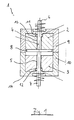
- FIG. 1 shows a stroke actuator 1 for an internal combustion engine with an electric valve train.
- the stroke actuator 1 has a first electromagnet with a first magnetic core 2 and a second electromagnet axially spaced therefrom with an associated one second magnetic core 3.
- the magnetic cores 2, 3 are preferred formed by laminated cores. They each have a passage, which in the The following is always referred to as a through hole 4, 5.
- the shaft sections 6, 7 of an axially displaceable armature extend in these through bores 4, 5.
- the armature has one Anchor plate 8 on. By energizing one or the other electromagnet the anchor can be moved axially.
- the electromagnets are arranged in a housing.
- the case is through two housing parts 9, 10 formed.
- the housing part 9 is the first electromagnet, the housing part 10 assigned to the second electromagnet.
- the housing parts 9, 10 are castings. In the manufacture of the magnetic cores 2, 3 with cast.
- the through holes 4, 5 a slightly larger diameter than the shaft sections 6, 7.
- the Housing parts are initially provided in the magnetic cores 2, 3 Through holes poured out with housing material. After curing the poured "through holes" 4, 5 drilled out with a diameter slightly smaller than that Diameter of the through holes 4, 5 and which is essentially the Diameter of the shaft sections 6, 7 corresponds.
- Die Slide bearing guides are an integral part of each assigned Housing part 9, 10. The anchor shaft is thus guided directly in the housing. separate Guide bushings are therefore not required.
- the magnetic cores each have a cup-shaped Recess 13, 14 into which the assigned housing part 9 or 10 extends, which enables a very compact design.
- the housing parts 9, 10 are made of one good thermally conductive material, e.g. made of a cast aluminum material.
Landscapes
- Engineering & Computer Science (AREA)
- Physics & Mathematics (AREA)
- Electromagnetism (AREA)
- Power Engineering (AREA)
- Mechanical Engineering (AREA)
- General Engineering & Computer Science (AREA)
- Valve Device For Special Equipments (AREA)
Abstract
Description
Claims (5)
- Hubaktuator (1) für Verbrennungsmotoren mit elektrischem Ventiltrieb, mit einem ersten Elektromagnet (2) und einem zweiten Elektromagnet (3), die in einem Abstand voneinander angeordnet sind, und die jeweils ein Joch und eine daran angeordnete Spule aufweisen,
einem Anker, der einen Ankerschaft (6, 7) und eine Ankerplatte (8) aufweist, wobei die Ankerplatte (8) im Bereich zwischen den beiden Elektromagneten (2, 3) angeordnet ist und der Anker (6 - 8) durch Bestromen eines der Elektromagneten (2, 3) in die eine bzw. die andere Richtung verschiebbar ist, wobei in mindestens einem der beiden Joche eine Gleitlagerführung vorgesehen ist, in welcher der Ankerschaft geführt ist und
einem Gehäuseteil (9, 10), das einen der Elektromagneten (2, 3) zumindest teilweise umgibt,
dadurch gekennzeichnet, dass das Gehäuseteil (9, 10) und die Gleitlagerführung aus einem Gusswerkstoff besteht, wobei die Gleitlagerführung integraler Bestandteil des Gehäuseteils ist. - Hubaktuator (1) nach Anspruch 1, wobei jedem der beiden Elektromagneten (2, 3) ein Gehäuseteil (9, 10) zugeordnet ist und in jedem der beiden Gehäuseteile (9, 10) eine als Gleitlagerführung (11, 12) für den Ankerschaft (6, 7) fungierende buchsenartige Ausnehmung vorgesehen ist und die Gleitlagerführungen jeweils integraler Bestandteil des zugeordneten Gehäuseteils sind.
- Hubaktuator (1) nach einem der Ansprüche 1 oder 2, wobei die beiden Joche jeweils in das zugeordnete Gehäuseteil (9, 10) eingegossen sind.
- Hubaktuator (1) nach Anspruch 3, wobei die Magnetkerne (2, 3) auf der dem zugeordneten Gehäuseteil (9, 10) zugewandten Seite im Bereich des Durchgangs (11, 12) des zugeordneten Gehäuseteils (9, 10) jeweils eine topfförmige Ausnehmung (13, 14) aufweisen, die von dem zugeordneten Gehäuseteil (9, 10) ausgefüllt ist.
- Hubaktuator 81) nach einem der Ansprüche 1 bis 5, wobei das Gehäuseteil (9, 10) aus einer Aluminium-Legierung besteht.
Applications Claiming Priority (2)
| Application Number | Priority Date | Filing Date | Title |
|---|---|---|---|
| DE10321017A DE10321017A1 (de) | 2003-05-10 | 2003-05-10 | Hubaktuator für Verbrennungsmotoren mit elektrischem Ventiltrieb |
| DE10321017 | 2003-05-10 |
Publications (2)
| Publication Number | Publication Date |
|---|---|
| EP1477637A2 true EP1477637A2 (de) | 2004-11-17 |
| EP1477637A3 EP1477637A3 (de) | 2010-01-27 |
Family
ID=33016331
Family Applications (1)
| Application Number | Title | Priority Date | Filing Date |
|---|---|---|---|
| EP04008731A Withdrawn EP1477637A3 (de) | 2003-05-10 | 2004-04-13 | Hubaktuator für Verbrennungsmotoren mit elektrischem Ventiltrieb |
Country Status (2)
| Country | Link |
|---|---|
| EP (1) | EP1477637A3 (de) |
| DE (1) | DE10321017A1 (de) |
Citations (1)
| Publication number | Priority date | Publication date | Assignee | Title |
|---|---|---|---|---|
| DE10108714A1 (de) | 2001-02-23 | 2002-09-05 | Daimler Chrysler Ag | Vorrichtung zur Verriegelung bzw. Entriegelung eines elektromagnetischen Aktuators und Verfahren hierzu |
Family Cites Families (10)
| Publication number | Priority date | Publication date | Assignee | Title |
|---|---|---|---|---|
| DE1230499B (de) * | 1961-07-25 | 1966-12-15 | Magnetschultz G M B H Spezialf | Drehstrommagnet mit allseits geschlossenem Gehaeuse |
| DE3708373C1 (de) * | 1987-03-14 | 1988-07-14 | Fleck Andreas | Verfahren zum Betreiben eines Einlassventiles einer Brennkraftmaschine |
| DE19611547A1 (de) * | 1996-03-23 | 1997-09-25 | Bayerische Motoren Werke Ag | Elektromagnetische Betätigungsvorrichtung für Brennkraftmaschinen-Hubventile |
| DE19838101A1 (de) * | 1998-08-21 | 2000-02-24 | Bayerische Motoren Werke Ag | Elektromagnetischer Aktuator zur Betätigung eines Gaswechselventils einer Brennkraftmaschine |
| DE19838102A1 (de) * | 1998-08-21 | 2000-02-24 | Bayerische Motoren Werke Ag | Rahmenartiges Gehäuse eines elektromagnetischen Aktuators zur Ventilbetätigung, insbesondere in Brennkraftmaschinen |
| DE19855730A1 (de) * | 1998-12-03 | 2000-06-08 | Fev Motorentech Gmbh | Elektromagnetischer Aktuator mit mehrteiligem Gehäuse |
| DE10009927A1 (de) * | 2000-03-01 | 2001-09-06 | Bayerische Motoren Werke Ag | Elektromagnetischer Hubaktuator für einen Ventiltrieb einer Brennkraftmaschine |
| DE10042013A1 (de) * | 2000-08-26 | 2002-03-07 | Daimler Chrysler Ag | Elektromagnet |
| DE20100348U1 (de) * | 2001-01-10 | 2001-03-29 | FEV Motorentechnik GmbH, 52078 Aachen | Elektromagnetischer Aktuator zur Betätigung eines Gaswechselventils mit fixierter Öffnerfeder |
| DE10139447A1 (de) * | 2001-08-10 | 2003-02-20 | Conti Temic Microelectronic | Spulenaufbau |
-
2003
- 2003-05-10 DE DE10321017A patent/DE10321017A1/de not_active Withdrawn
-
2004
- 2004-04-13 EP EP04008731A patent/EP1477637A3/de not_active Withdrawn
Patent Citations (1)
| Publication number | Priority date | Publication date | Assignee | Title |
|---|---|---|---|---|
| DE10108714A1 (de) | 2001-02-23 | 2002-09-05 | Daimler Chrysler Ag | Vorrichtung zur Verriegelung bzw. Entriegelung eines elektromagnetischen Aktuators und Verfahren hierzu |
Also Published As
| Publication number | Publication date |
|---|---|
| EP1477637A3 (de) | 2010-01-27 |
| DE10321017A1 (de) | 2004-12-02 |
Similar Documents
| Publication | Publication Date | Title |
|---|---|---|
| DE69517335T2 (de) | Elektromagnetisch gelenktes ventil mit gelenkter armatur | |
| DE69825713T2 (de) | Elektromagnetischer Betätiger mit Verbundkernanordnung | |
| EP0796981B1 (de) | Elektromagnetische Betätigungsvorrichtung für Brennkraftmaschinen-Hubventile | |
| WO2010086058A1 (de) | Proportionalmagnet für ein hydraulisches wegeventil und verfahren zu dessen herstellung | |
| DE19534959B4 (de) | Ventilantriebsvorrichtung zum Antrieb eines Ventils eines Verbrennungsmotors | |
| EP0357938A1 (de) | Stelleinrichtung für ein Gaswechselventil einer Brennkraftmaschine | |
| EP1144812A1 (de) | Elektromagnetischer aktuator | |
| DE10053596A1 (de) | Elektromagnetischer Aktuator zur Betätigung eines Stellgliedes | |
| DE10035759A1 (de) | Elektromagnetischer Aktuator zur Betätigung eines Gaswechselventils einer Brennkraftmaschine | |
| DE112006001605B4 (de) | Elektromagnetische Betätigungsvorrichtung und Verfahren zur Steuerung eines Strömungsmittelflusses | |
| DE60030652T2 (de) | Motorwelle für Dreh-/Direksteuerung Motorwandler und Verfahren für ihre Herstellung | |
| DE29620741U1 (de) | Schmalbauender elektromagnetischer Aktuator | |
| DE19535974C2 (de) | Elektromagnetische Ventileinrichtung und Verfahren zu deren Herstellung | |
| EP1059646A1 (de) | Aktor zur elektromagnetischen Ventilsteuerung | |
| DE4037824A1 (de) | Hydraulische stelleinrichtung | |
| EP3918619B1 (de) | Elektromagnetische stellvorrichtung | |
| EP1477637A2 (de) | Hubaktuator für Verbrennungsmotoren mit elektrischem Ventiltrieb | |
| WO2009109369A1 (de) | Elektromagnetische stellvorrichtung | |
| DE102011012020B4 (de) | Nockenwelle mit Nockenwellenversteller | |
| DE69618551T2 (de) | Elektromagnetischer Betätiger mit Kern mit niedrigem Seitenverhältnis | |
| DE19859116B4 (de) | Elektromagnet | |
| DE112007001110T5 (de) | Elektromagnetisch angetriebenes Ventil | |
| DE10223673A1 (de) | Vorrichtung zum Betätigen eines Gaswechselventils einer Brennkraftmaschine | |
| EP1063660A1 (de) | Längsgeblechter Jochkörper für einen Elektromagneten | |
| DE10316643B4 (de) | Magnetventil |
Legal Events
| Date | Code | Title | Description |
|---|---|---|---|
| PUAI | Public reference made under article 153(3) epc to a published international application that has entered the european phase |
Free format text: ORIGINAL CODE: 0009012 |
|
| AK | Designated contracting states |
Kind code of ref document: A2 Designated state(s): AT BE BG CH CY CZ DE DK EE ES FI FR GB GR HU IE IT LI LU MC NL PL PT RO SE SI SK TR |
|
| AX | Request for extension of the european patent |
Extension state: AL HR LT LV MK |
|
| PUAL | Search report despatched |
Free format text: ORIGINAL CODE: 0009013 |
|
| AK | Designated contracting states |
Kind code of ref document: A3 Designated state(s): AT BE BG CH CY CZ DE DK EE ES FI FR GB GR HU IE IT LI LU MC NL PL PT RO SE SI SK TR |
|
| AX | Request for extension of the european patent |
Extension state: AL HR LT LV MK |
|
| RIC1 | Information provided on ipc code assigned before grant |
Ipc: H01F 7/16 20060101ALI20091218BHEP Ipc: F01L 9/04 20060101AFI20040826BHEP |
|
| 17P | Request for examination filed |
Effective date: 20100211 |
|
| 17Q | First examination report despatched |
Effective date: 20100719 |
|
| AKX | Designation fees paid |
Designated state(s): DE FR GB IT |
|
| STAA | Information on the status of an ep patent application or granted ep patent |
Free format text: STATUS: THE APPLICATION IS DEEMED TO BE WITHDRAWN |
|
| 18D | Application deemed to be withdrawn |
Effective date: 20101130 |