EP1477437A2 - Modular construction system for a conveyor for longitudinal or transversal transport of piece-goods carriers - Google Patents
Modular construction system for a conveyor for longitudinal or transversal transport of piece-goods carriers Download PDFInfo
- Publication number
- EP1477437A2 EP1477437A2 EP04007438A EP04007438A EP1477437A2 EP 1477437 A2 EP1477437 A2 EP 1477437A2 EP 04007438 A EP04007438 A EP 04007438A EP 04007438 A EP04007438 A EP 04007438A EP 1477437 A2 EP1477437 A2 EP 1477437A2
- Authority
- EP
- European Patent Office
- Prior art keywords
- aluminum
- modular system
- plastic hollow
- hollow profile
- support
- Prior art date
- Legal status (The legal status is an assumption and is not a legal conclusion. Google has not performed a legal analysis and makes no representation as to the accuracy of the status listed.)
- Withdrawn
Links
Images


Classifications
-
- B—PERFORMING OPERATIONS; TRANSPORTING
- B65—CONVEYING; PACKING; STORING; HANDLING THIN OR FILAMENTARY MATERIAL
- B65G—TRANSPORT OR STORAGE DEVICES, e.g. CONVEYORS FOR LOADING OR TIPPING, SHOP CONVEYOR SYSTEMS OR PNEUMATIC TUBE CONVEYORS
- B65G21/00—Supporting or protective framework or housings for endless load-carriers or traction elements of belt or chain conveyors
-
- B—PERFORMING OPERATIONS; TRANSPORTING
- B65—CONVEYING; PACKING; STORING; HANDLING THIN OR FILAMENTARY MATERIAL
- B65G—TRANSPORT OR STORAGE DEVICES, e.g. CONVEYORS FOR LOADING OR TIPPING, SHOP CONVEYOR SYSTEMS OR PNEUMATIC TUBE CONVEYORS
- B65G13/00—Roller-ways
- B65G13/02—Roller-ways having driven rollers
- B65G13/04—Roller-ways having driven rollers all rollers driven
-
- B—PERFORMING OPERATIONS; TRANSPORTING
- B65—CONVEYING; PACKING; STORING; HANDLING THIN OR FILAMENTARY MATERIAL
- B65G—TRANSPORT OR STORAGE DEVICES, e.g. CONVEYORS FOR LOADING OR TIPPING, SHOP CONVEYOR SYSTEMS OR PNEUMATIC TUBE CONVEYORS
- B65G13/00—Roller-ways
- B65G13/02—Roller-ways having driven rollers
- B65G13/06—Roller driving means
- B65G13/07—Roller driving means having endless driving elements
-
- B—PERFORMING OPERATIONS; TRANSPORTING
- B65—CONVEYING; PACKING; STORING; HANDLING THIN OR FILAMENTARY MATERIAL
- B65G—TRANSPORT OR STORAGE DEVICES, e.g. CONVEYORS FOR LOADING OR TIPPING, SHOP CONVEYOR SYSTEMS OR PNEUMATIC TUBE CONVEYORS
- B65G15/00—Conveyors having endless load-conveying surfaces, i.e. belts and like continuous members, to which tractive effort is transmitted by means other than endless driving elements of similar configuration
- B65G15/10—Conveyors having endless load-conveying surfaces, i.e. belts and like continuous members, to which tractive effort is transmitted by means other than endless driving elements of similar configuration comprising two or more co-operating endless surfaces with parallel longitudinal axes, or a multiplicity of parallel elements, e.g. ropes defining an endless surface
- B65G15/12—Conveyors having endless load-conveying surfaces, i.e. belts and like continuous members, to which tractive effort is transmitted by means other than endless driving elements of similar configuration comprising two or more co-operating endless surfaces with parallel longitudinal axes, or a multiplicity of parallel elements, e.g. ropes defining an endless surface with two or more endless belts
-
- B—PERFORMING OPERATIONS; TRANSPORTING
- B65—CONVEYING; PACKING; STORING; HANDLING THIN OR FILAMENTARY MATERIAL
- B65G—TRANSPORT OR STORAGE DEVICES, e.g. CONVEYORS FOR LOADING OR TIPPING, SHOP CONVEYOR SYSTEMS OR PNEUMATIC TUBE CONVEYORS
- B65G21/00—Supporting or protective framework or housings for endless load-carriers or traction elements of belt or chain conveyors
- B65G21/02—Supporting or protective framework or housings for endless load-carriers or traction elements of belt or chain conveyors consisting essentially of struts, ties, or like structural elements
- B65G21/06—Supporting or protective framework or housings for endless load-carriers or traction elements of belt or chain conveyors consisting essentially of struts, ties, or like structural elements constructed to facilitate rapid assembly or dismantling
-
- B—PERFORMING OPERATIONS; TRANSPORTING
- B65—CONVEYING; PACKING; STORING; HANDLING THIN OR FILAMENTARY MATERIAL
- B65G—TRANSPORT OR STORAGE DEVICES, e.g. CONVEYORS FOR LOADING OR TIPPING, SHOP CONVEYOR SYSTEMS OR PNEUMATIC TUBE CONVEYORS
- B65G21/00—Supporting or protective framework or housings for endless load-carriers or traction elements of belt or chain conveyors
- B65G21/20—Means incorporated in, or attached to, framework or housings for guiding load-carriers, traction elements or loads supported on moving surfaces
- B65G21/22—Rails or the like engaging sliding elements or rollers attached to load-carriers or traction elements
-
- B—PERFORMING OPERATIONS; TRANSPORTING
- B65—CONVEYING; PACKING; STORING; HANDLING THIN OR FILAMENTARY MATERIAL
- B65G—TRANSPORT OR STORAGE DEVICES, e.g. CONVEYORS FOR LOADING OR TIPPING, SHOP CONVEYOR SYSTEMS OR PNEUMATIC TUBE CONVEYORS
- B65G39/00—Rollers, e.g. drive rollers, or arrangements thereof incorporated in roller-ways or other types of mechanical conveyors
- B65G39/02—Adaptations of individual rollers and supports therefor
-
- B—PERFORMING OPERATIONS; TRANSPORTING
- B65—CONVEYING; PACKING; STORING; HANDLING THIN OR FILAMENTARY MATERIAL
- B65G—TRANSPORT OR STORAGE DEVICES, e.g. CONVEYORS FOR LOADING OR TIPPING, SHOP CONVEYOR SYSTEMS OR PNEUMATIC TUBE CONVEYORS
- B65G2207/00—Indexing codes relating to constructional details, configuration and additional features of a handling device, e.g. Conveyors
- B65G2207/16—Convertible to another type of conveyor
-
- B—PERFORMING OPERATIONS; TRANSPORTING
- B65—CONVEYING; PACKING; STORING; HANDLING THIN OR FILAMENTARY MATERIAL
- B65G—TRANSPORT OR STORAGE DEVICES, e.g. CONVEYORS FOR LOADING OR TIPPING, SHOP CONVEYOR SYSTEMS OR PNEUMATIC TUBE CONVEYORS
- B65G2207/00—Indexing codes relating to constructional details, configuration and additional features of a handling device, e.g. Conveyors
- B65G2207/30—Modular constructions
Definitions
- the invention relates to a modular system for a conveyor for longitudinal or transverse conveying of general cargo carriers, such as Pallets, skids or the like with side rails, with the cross member connecting the side members with Support feet and with driven load-bearing Funding for general cargo carriers.
- general cargo carriers such as Pallets, skids or the like with side rails
- the aim of the present invention is therefore a simplifying modular system for a conveyor of to create the kind described above, the opposite previous solutions with regard to manufacturing costs, Assembly costs, process costs and delivery time for the conveyor is significantly improved.
- the invention proposes that in the case of a generic conveyor, the funding receiving side members each releasably with the Cross-frame element connectable connection-stiff aluminum or Plastic hollow profile is for optional admission from driven idlers or from insertable ones Sliding plates for a shoulder strap is formed.
- Core of present invention is the torsionally rigid aluminum or Plastic hollow profile that is suitable both for idlers and is also designed for risers. This will make it possible with one and the same side member of the conveyor both Funding principles, namely both the longitudinal and also the cross conveying of general cargo carriers.
- the universal usable side members are only by inserting either of idlers or inserting sliding plates adapted to the desired purpose and to the Cross frame elements screwed on.
- the sponsor can as with be assembled in a kit, the number of components used is reduced to a minimum, that Assembly of the conveyor is very simple.
- the aluminum or plastic hollow profile one of its long sides open to accommodate the idlers is and on the opposite side to form a Pad for the sliding plate is largely closed, and that by rotating the aluminum or plastic hollow profile by 180 ° around its longitudinal axis for each required purpose required side in use position with the Cross frame element is connectable.
- the aluminum or plastic hollow profile is preferably in the Cross section on two opposite long sides like this shaped that it has the idlers on one long side record and on the opposite side the Can support sliding plates for a riser.
- the aluminum or Plastic hollow profile with an H-shaped cross-section is, the idlers between the two legs of the H-shaped cross-section are stored and the opposite leg of the H-shaped cross section in their end area are closed by a transverse bulkhead, the forms the support for the sliding plate, the aluminum or Plastic hollow profile is symmetrical.
- Symmetrical training is reasonably required to the fastening of the aluminum or plastic hollow profile to simplify the side members. So uniform Attachment points are provided for both funding principles which is a turning of the profile about its longitudinal axis and Allow fastening.
- the H-shaped cross section is particularly suitable for that Storage of the idlers between the two legs of this H-profile.
- a transverse bulkhead between the legs of the H-profile on the opposite side offers a cheap one Support for the sliding plate on which the carrying belt rests or is removed.
- the Profile cross-section high strength in the transverse direction achieved which can be further reinforced if after Another feature of the invention is the area between the Transverse bulkhead and the web of the H-shaped cross section Aluminum or plastic hollow profile an additional Contains cross bracing.
- the transverse stiffening can be according to a favorable characteristic of the Invention also by a in the longitudinal direction of the aluminum or Plastic hollow profile extending tube profile formed against which the inside of the legs of the Support aluminum profile.
- pipe profiles have a high profile Transverse stability; is such a tube profile in the Aluminum or plastic hollow profile with molded in, see above this results in high stability for the intended purpose with low weight of the aluminum or plastic material.
- aluminum or Plastic hollow profile and its cross stiffeners from one high-precision extruded profile can be formed.
- Aluminum or Plastic hollow profiles can be Manufacture extrusion processes very precisely, with the Shape is almost unlimited. This makes it to use the present invention.
- T-slots for Fasteners are provided. These T-slots can of course also be used for other components, to be attached to the conveyor, e.g. Initiators or Sensors.
- the aluminum or plastic hollow profile as a roller bar can be assembled prefabricated with the support rollers used.
- the roller strips can Be prepared for the intended use and quickly and easily with the cross frame element as required get connected.
- roller bar in the area of the idlers with a cover plate can be closed with segments of the idlers penetrable recesses is provided. This plate makes sure the areas between the roles are protected, for example from unintentional Reach in or before any of them fall Objects.
- the rollers of the roller bar can be used for another Feature of the invention from a cut to length, tubular trained aluminum extruded profile be formed in the Hubs on both sides to accommodate the idler roller bearings are press-fit.
- the manufacture of the idlers is by simplified this proposal considerably.
- Roles are in the required roll width from the tubular Extruded profile separated.
- the hubs are in the tube pressed right and left and form the fixed bearing for the Axes of the roles.
- a Designed feature of the invention may be provided to the To form hubs wheel flanges to guide the general cargo carriers.
- the idlers centrally circumferential or, protected by the upper flange of the extruded aluminum profile laterally offset, with a groove provided, in the one for all idlers of a roller bar common transmission belt can be inserted.
- this transmission belt a toothed belt and the Idlers are in the removal area of the transmission belt provided according to toothed peripheral surface. To this A high driving torque can be transmitted in this way.
- the cross frame elements to which the side members can be screwed are according to another feature of the invention from one angled sheet metal with molded support legs. This makes it very simple and inexpensive to manufacture Element created that is also modular with the Side members can be screwed and attached to the conveyor can be delivered prefabricated.
- the support legs of the Cross frame elements are according to another feature of the Invention, height-adjustable support feet introduced on the floor, with which the conveyor is aligned on the floor can.
- the cross frame elements according to the invention are in Provide the direction of conveyance of the general cargo carriers with recesses, can be used in the cable ducts running along the conveyor are. These cable ducts are also modular in the Cross frame elements can be used and consist of prefabricated Divide. This simplifies the laying of the cables Accessibility is made easier.
- a particularly affordable solution to facilitate the Transport and to reduce the transport volume before that the cross frame elements of the preferably short Conveyor sections around one of the fastening screws 90 ° in the longitudinal plane of the bilateral aluminum or Plastic hollow profiles are pivotable and after Swing back and screw the aluminum or Plastic hollow profiles on the cross frame elements with at least one other fastening screw in the Operating situation can be determined.
- the support legs of the Cross frame elements can be folded up for transport, so that the height of the conveyor is practically the same as the Aluminum or plastic hollow profiles is limited. Without the support legs of the Cross frame elements through 90 ° to the conveyor in the Swivel operating position where it can be done in a few easy steps be fixed.
- the conveyor according to the invention has a modular structure, whereby each conveyor made of at least two aluminum or plastic hollow profiles with sliding plates or roller strips, at least a cross frame element, at least one drive module and there is at least two transport or transmission belts.
- the drive for the funding is Invention provided an integral drive, d. H. on Direct drive of the transport or transmission belts.
- This integral drive is preferably a drum motor which installed on the last roll of the conveyor.
- roller strips of aluminum or plastic hollow profiles with, depending on the different uses, in support rollers positioned at different center distances are prefabricated. For example, for the promotion of Skids another (larger) center distance for idlers needed than usual for the longitudinal conveyance of pallets is. Correspondingly prefabricated strips are made as needed screwed to the cross frame elements.
- the invention has a number of advantages on. It replaces the usual roles or shafts with a idler roller that is the first thing ever Modular system enables.
- the essential part this system is the aluminum or plastic hollow profile, which is preferably produced in the extrusion process. This profile is designed so that by a 180 ° rotation either support surfaces or rollers come into effect that Cross frame elements are simply inexpensive and functional manufactured, easy to assemble and during transport fold away to save transport space.
- the simple one Modular system creates an inexpensive and economic subsidies, which also significant to the operator Brings advantages, namely price advantages and technical Benefits. This enables the conveyor according to the invention For example, the quick change of shoulder strap and Roller bar without dismantling the complete conveyor.
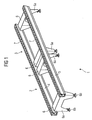
- a conveyor is designated by 1, which from two conveyor sections 2 and 3 from the modular system according to the invention is composed.
- This Modular system or the conveyor essentially consists of the side members, which in the exemplary embodiment are made of aluminum hollow profiles 4 and 5 are formed. These aluminum hollow profiles 4 and 5 are laterally screwed to cross frame elements 6, which consist of folded sheet metal parts.
- the Cross frame elements have integrally formed legs 6a on which height-adjustable feet 6b are arranged.
- FIG. 2 There is a cross section through an aluminum hollow profile 4, 5 of the invention.
- the profile can be seen in the essentially H-shaped, the upper, the large H-forming leg 8 in its end regions by a Transverse bulkhead 9 are interconnected, on which the 10th indicated shoulder strap with the interposition of a Sliding plate 11 is supported.
- the one on the other side of the Web 12 of the H-shaped aluminum hollow profile extending Legs 13 are not closed to the outside, between them become, as will be explained later, the idlers used.
- the aluminum hollow profile is turned through 180 °, like it is shown in Figure 3. The same parts are the same there designated.
- With 14 are in Figures 2 and 3 along the Alu hollow profile extending holes in which Fastening or centering elements for assembly neighboring sponsors can be brought.
- the cross section of the aluminum hollow profile be designed in a variety of ways.
- Figure 4 is for Stiffening of the aluminum hollow profile in the longitudinal direction running pipe profile cross section 15 recognizable against the the side walls 8 and 13 of the H-shaped cross section Support over ribs 15a.
- Fastening grooves 16 are provided with which the aluminum hollow profiles on the cross frame elements, preferably with With the help of hammer head screws, can be screwed on.
- a shoulder strap at 10 in cross section recognizable, the lower run within the aluminum hollow profile, as marked at 10a, is traceable.
- the sliding plate 11 Between the Carrying belt 10 and the transverse bulkhead 9 is the sliding plate 11 recognizable on which the riser slides. In the area below the leg 13 of the H-profile are receiving grooves 17 recognizable, in which axes of the idlers can be stored on both sides are.
- the support rollers 7 can be better supported in FIG. 5 recognize where you can also see the ends of the idler Axis 18 can see. This was evident in Figure 4 shown aluminum hollow profile by 180 ° around its longitudinal axis rotated so that the tubular cross bracing is below the idler roller, which is between the legs 13th is stored.
- the idler 7 is on both sides with wheel flanges 19 to guide piece goods carriers, the support roller 7 itself is provided with a circumferential groove 20 in the center, in which is a transmission belt 21 with which the Idlers over the drive (not shown here) are drivable.
- Figure 6 shows a schematic cross section Arrangement of the two aluminum hollow profiles 4 and 5 on the Cross frame member 23 made of a folded sheet is shaped.
- the cross frame element 23 is aligned with (in Direction seen perpendicular to the plane of the drawing) adjacent Cross frame elements 23 recesses 24 in the sheet, in the one Cable duct can be used, as well as openings 25 for Installations, recordings for switch boxes 26 and on the Legs 6a adjustable feet 6b.
- the aluminum hollow profiles 4 and 5 are attached to the folded sheet metal parts of the Cross frame element 23 (in a manner not shown) screwed.
- the aluminum hollow profiles 4 and 5 are symmetrical and can be attached on both sides and rotated by 180 ° become.
- FIGS. 7a-7c are those according to the invention Recognize cross frame parts in a perspective view.
- the cross frame elements 22 consist folded sheet metal parts, the side with 27 contact surfaces form for the aluminum hollow profiles 4, 5 and there with holes 28a and 28b for the fastening screws of these hollow aluminum profiles are.
- the Alignment of the conveyor takes place via the support feet 6a.
- the use of two adjacent bores 28a and 28b enables space-saving transport of the conveyor if, as the invention proposes, the cross frame elements 23 in be folded in a direction in which the support legs 6a are positioned parallel to the aluminum hollow profiles 4.5.
- the conveyor is shown in Figure 8a in the transport position, where three conveyor elements shown stacked one above the other are.
- the operating position of the conveyor is in Figure 8b shown.
- a relatively large one can also be seen here Distance between the idlers 7, which indicates that with this Conveyor a load carrier is transported in the longitudinal direction, for example a skid.
- FIGS. 9a-c Another advantage of the invention is shown in FIGS. 9a-c shown.
- Figures 9b and 9c each in the Side view and top view, an aluminum hollow profile 4, 5 shown with the support rollers 7 stored therein, which all via a common toothed belt 30 Transmission belt 21 from an integral drive 29 are driven.
- This is designed as a drum motor ( Figure 9a) around which the toothed belt 30 for transmitting the Drive torque is guided.
- 5 Roller bar is a deflection roller 31 below the supporting plane pivoted or slidably provided, with the help of Transmission belt 30 is tensionable.
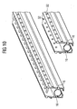
- FIG. 10 again shows an inventive one H-shaped three-dimensional aluminum hollow section shown.
- the prepared holes 32 which will later be the axes of the Take up idlers 7.
- These are in the illustration above Shown axes inserted into the holes 32 on them the idlers 7 rotate.
- They can also be seen lengthways of the aluminum hollow profile running T-slots 16 for attachment the aluminum hollow profiles on the cross frame elements 23, but also for attaching attachments, such as initiators, Control boxes etc.
Abstract
Description
Die Erfindung betrifft ein Baukastensystem für einen Förderer zum Längs- oder Querfördern von Stückgutträgern, wie Paletten, Skids oder dgl. mit seitlichen Längsträgern, mit die Längsträger verbindenden Querrahmenelementen mit Stützfüßen und mit angetriebenen lastabtragenden Fördermitteln für die Stückgutträger.The invention relates to a modular system for a conveyor for longitudinal or transverse conveying of general cargo carriers, such as Pallets, skids or the like with side rails, with the cross member connecting the side members with Support feet and with driven load-bearing Funding for general cargo carriers.
Zum Fördern von Stückgutträgern sind unterschiedliche Systeme bekannt; im wesentlichen unterscheidet man rollende Abtragung der Lastträger auf Rollenförderern und gleitende Abtragung, wobei der Lastträger auf Tragelementen aufliegt, die gleitend auf einem Untergrund abgetragen werden. Die Lastträger für gleitende Abtragung kann man grob unterscheiden in Traggurte und Ketten. Traggurt- oder Kettenförderer sind besonders geeignet, um einen sog. Quertransport von Paletten zu ermöglichen, der häufig erforderlich ist und für den Rollenförderer wegen des zu überbrückenden Rollenabstandes ungeeignet sind. Für die Herstellung von Förderern der vorbeschriebenen Art entsteht ein erheblicher Aufwand, dadurch, dass praktisch beide Förderprinzipien nebeneinander zur Verfügung gestellt werden müssen, was ein sehr großes Sortiment von Bauteilen mit entsprechender Lager- und Ersatzteilhaltung bedeutet und was dadurch letztlich den Förderer deutlich verteuert. Individuelle Kundenlösungen und spezielle Konstruktionen verteuern grundsätzlich durch hohe Herstellungs- und Konstruktionskosten, auch entstehen Nachteile für.den Kunden durch lange Lieferzeiten.Different systems are available for conveying general cargo carriers known; one essentially distinguishes rolling ablation the load carrier on roller conveyors and sliding removal, the load carrier rests on support elements that slide be removed on a surface. The load bearers for sliding abrasion can be roughly differentiated into risers and chains. Carrier belt or chain conveyors are special suitable for a so-called cross transport of pallets enable that is often required and for whom Roller conveyor because of the roller gap to be bridged are unsuitable. For the production of conveyors of the of the type described above, there is considerable effort, in that practically both funding principles coexist must be made available, which is a very large Assortment of components with corresponding storage and Stocking spare parts means what ultimately means that Conveyors significantly more expensive. Individual customer solutions and special constructions generally become more expensive due to high Manufacturing and construction costs, also arise Disadvantages for the customer due to long delivery times.
Ziel der vorliegenden Erfindung ist es deshalb, ein vereinfachendes Baukastensystem für einen Förderer der eingangs beschriebenen Art zu schaffen, das gegenüber bisherigen Lösungen hinsichtlich Herstellkosten, Montagekosten, Prozesskosten und Lieferzeit für den Förderer deutlich verbessert ist.The aim of the present invention is therefore a simplifying modular system for a conveyor of to create the kind described above, the opposite previous solutions with regard to manufacturing costs, Assembly costs, process costs and delivery time for the conveyor is significantly improved.
Zur Lösung der Aufgabe wird erfindungsgemäß vorgeschlagen, dass bei einem gattungsgemäßen Förderer der die Fördermittel aufnehmende Längsträger jeweils ein lösbar mit dem Querrahmenelement verbindbares verbindungssteifes Aluminiumoder Kunststoff-Hohlprofil ist, das zur wahlweisen Aufnahme von angetriebenen Tragrollen oder von einlegbaren Gleitblechen für einen Traggurt ausgebildet ist. Kern der vorliegenden Erfindung ist das verwindungssteife Aluminiumoder Kunststoff-Hohlprofil, das sowohl für Tragrollen als auch für Traggurte gestaltet ist. Damit wird es möglich, mit ein- und demselben Längsträger des Förderers beide Förderprinzipien durchzuführen, nämlich sowohl das Längs- als auch das Querfördern von Stückgutträgern. Die universell verwendbaren Längsträger werden lediglich durch das Einsetzen entweder von Tragrollen oder das Einlegen von Gleitblechen dem jeweils gewünschten Zweck angepasst und an die Querrahmenelemente angeschraubt. Der Förderer kann so wie bei einem Baukasten zusammengestellt werden, die Zahl der verwendeten Bauteile wird auf ein Minimum reduziert, die Montage des Förderers ist sehr einfach.To achieve the object, the invention proposes that in the case of a generic conveyor, the funding receiving side members each releasably with the Cross-frame element connectable connection-stiff aluminum or Plastic hollow profile is for optional admission from driven idlers or from insertable ones Sliding plates for a shoulder strap is formed. Core of present invention is the torsionally rigid aluminum or Plastic hollow profile that is suitable both for idlers and is also designed for risers. This will make it possible with one and the same side member of the conveyor both Funding principles, namely both the longitudinal and also the cross conveying of general cargo carriers. The universal usable side members are only by inserting either of idlers or inserting sliding plates adapted to the desired purpose and to the Cross frame elements screwed on. The sponsor can as with be assembled in a kit, the number of components used is reduced to a minimum, that Assembly of the conveyor is very simple.
In einer günstigen Ausgestaltung der Erfindung ist vorgesehen, dass das Aluminium- oder Kunststoff-Hohlprofil an einer seiner Längsseiten zur Aufnahme der Tragrollen offen ist und auf der gegenüberliegenden Seite zur Bildung einer Auflage für das Gleitblech weitgehend geschlossen ist, und dass durch Drehung des Aluminium- oder Kunststoff-Hohlprofils um 180° um seine Längsachse die für den jeweils erforderlichen Zweck benötigte Seite in Gebrauchslage mit dem Querrahmenelement verbindbar ist.In a favorable embodiment of the invention provided that the aluminum or plastic hollow profile one of its long sides open to accommodate the idlers is and on the opposite side to form a Pad for the sliding plate is largely closed, and that by rotating the aluminum or plastic hollow profile by 180 ° around its longitudinal axis for each required purpose required side in use position with the Cross frame element is connectable.
Vorzugsweise ist das Aluminium- oder Kunststoff-Hohlprofil im Querschnitt an zwei gegenüberliegenden Längsseiten so geformt, dass es auf der einen Längsseite die Tragrollen aufnehmen und auf der gegenüberliegenden Seite die Gleitbleche für einen Traggurt abstützen kann. Durch einfaches Drehen des Aluminium- oder Kunststoff-Hohlprofils um 180° um seine Längsachse und Anschrauben an die Querrahmenelemente kann in einfacher Weise mit ein- und demselben Aluminium- oder Kunststoff-Hohlprofil ein Rollenförderer oder ein Traggurtförderer gebildet werden; besondere unterschiedliche Profile sind nicht erforderlich.The aluminum or plastic hollow profile is preferably in the Cross section on two opposite long sides like this shaped that it has the idlers on one long side record and on the opposite side the Can support sliding plates for a riser. By simple turning of the aluminum or plastic hollow profile by 180 ° around its longitudinal axis and screwing onto the Cross frame elements can be easily with and the same aluminum or plastic hollow profile Roller conveyor or a carrying belt conveyor are formed; special different profiles are not required.
Vorteilhafterweise ist vorgesehen, dass das Aluminium- oder Kunststoff-Hohlprofil im Querschnitt H-förmig ausgebildet ist, wobei die Tragrollen zwischen den beiden Schenkeln des H-förmigen Querschnitts gelagert sind und die gegenüberliegenden Schenkel des H-förmigen Querschnitts in ihrem Endbereich durch ein Querschott verschlossen sind, das die Auflage für das Gleitblech bildet, wobei das Aluminiumoder Kunststoff-Hohlprofil symmetrisch ausgebildet ist. Die symmetrische Ausbildung ist sinnvollerweise erforderlich, um die Befestigung des Aluminium- oder Kunststoff-Hohlprofils an den Längsträgern zu vereinfachen. So können einheitliche Befestigungspunkte für beide Förderprinzipien vorgesehen werden, die ein Drehen des Profils um seine Längsachse und Befestigen ermöglichen.It is advantageously provided that the aluminum or Plastic hollow profile with an H-shaped cross-section is, the idlers between the two legs of the H-shaped cross-section are stored and the opposite leg of the H-shaped cross section in their end area are closed by a transverse bulkhead, the forms the support for the sliding plate, the aluminum or Plastic hollow profile is symmetrical. The Symmetrical training is reasonably required to the fastening of the aluminum or plastic hollow profile to simplify the side members. So uniform Attachment points are provided for both funding principles which is a turning of the profile about its longitudinal axis and Allow fastening.
Der H-förmige Querschnitt eignet sich besonders gut für die Lagerung der Tragrollen zwischen den beiden Schenkeln dieses H-Profils. Ein Querschott zwischen den Schenkeln des H-Profils auf der gegenüberliegenden Seite bietet eine günstige Auflage für das Gleitblech, auf dem der Traggurt aufliegt bzw. abgetragen wird. Gleichzeitig wird durch den Profilquerschnitt eine hohe Festigkeit in Querrichtung erreicht, die zusätzlich verstärkt werden kann, wenn nach einem weiteren Merkmal der Erfindung der Bereich zwischen dem Querschott und dem Steg des im Querschnitt H-förmigen Aluminium- oder Kunststoff-Hohlprofils eine zusätzliche Querversteifung enthält. The H-shaped cross section is particularly suitable for that Storage of the idlers between the two legs of this H-profile. A transverse bulkhead between the legs of the H-profile on the opposite side offers a cheap one Support for the sliding plate on which the carrying belt rests or is removed. At the same time, the Profile cross-section high strength in the transverse direction achieved, which can be further reinforced if after Another feature of the invention is the area between the Transverse bulkhead and the web of the H-shaped cross section Aluminum or plastic hollow profile an additional Contains cross bracing.
Die Querversteifung kann nach einem günstigen Merkmal der Erfindung auch durch ein in Längsrichtung des Aluminium- oder Kunststoff-Hohlprofils verlaufendes Rohrprofil gebildet werden, gegen das sich die Innenseiten der Schenkel des Aluprofils abstützen. Rohrprofile haben bekanntlich eine hohe Stabilität in Querrichtung; wird ein solche Rohrprofil in das Aluminium- oder Kunststoff-Hohlprofil mit eingeformt, so ergibt sich eine für den vorgesehenen Zweck hohe Stabilität bei geringem Gewicht des Aluminium- oder Kunststoffmaterials.The transverse stiffening can be according to a favorable characteristic of the Invention also by a in the longitudinal direction of the aluminum or Plastic hollow profile extending tube profile formed against which the inside of the legs of the Support aluminum profile. As is known, pipe profiles have a high profile Transverse stability; is such a tube profile in the Aluminum or plastic hollow profile with molded in, see above this results in high stability for the intended purpose with low weight of the aluminum or plastic material.
Es ist besonders günstig, wenn das Aluminium- oder Kunststoff-Hohlprofil und dessen Querversteifungen aus einem hochgenauen Strangpressprofil gebildet werden. Aluminiumoder Kunststoff-Hohlprofile lassen sich im Strangpressverfahren sehr formgenau herstellen, wobei die Formgebung nahezu unbeschränkt ist. Dies macht sich die vorliegende Erfindung zu nutze.It is particularly convenient if the aluminum or Plastic hollow profile and its cross stiffeners from one high-precision extruded profile can be formed. aluminum or Plastic hollow profiles can be Manufacture extrusion processes very precisely, with the Shape is almost unlimited. This makes it to use the present invention.
Um die Aluminium- oder Kunststoff-Hohlprofile mit dem Querrahmenelement verbinden zu können, ist nach einem weiteren Merkmal der Erfindung vorgesehen, dass mindestens in den querversteiften, sich gegenüberliegenden Seitenbereichen des Aluminium- oder Kunststoff-Hohlprofils T-Nuten für Befestigungsmittel vorgesehen sind. Diese T-Nuten können selbstverständlich auch für andere Bauteile verwendet werden, die am Förderer zu befestigen sind, z.B. Initiatoren oder Sensoren.To the aluminum or plastic hollow profiles with the To be able to connect the cross frame element is one Another feature of the invention provided that at least in the cross-stiffened, opposite side areas of the aluminum or plastic hollow profile T-slots for Fasteners are provided. These T-slots can can of course also be used for other components, to be attached to the conveyor, e.g. Initiators or Sensors.
Als besonders günstig wird es angesehen, wenn erfindungsgemäß das Aluminium- oder Kunststoff-Hohlprofil als Rollenleiste mit den eingesetzten Tragrollen vorgefertigt montierbar ist. Auf diese Weise wird die Montage des Förderers, auch vor Ort sehr vereinfacht, die Rollenleisten können dem Verwendungszweck entsprechend vorbereitet sein und bedarfsgerecht schnell und einfach mit dem Querrahmenelement verbunden werden. It is considered to be particularly favorable if according to the invention the aluminum or plastic hollow profile as a roller bar can be assembled prefabricated with the support rollers used. In this way, the assembly of the conveyor, also on site very simplified, the roller strips can Be prepared for the intended use and quickly and easily with the cross frame element as required get connected.
In einer Ausgestaltung der Erfindung ist vorgesehen, dass die Rollenleiste im Bereich der Tragrollen mit einer Abdeckplatte verschließbar ist, die mit von Segmenten der Tragrollen durchdringbaren Ausnehmungen versehen ist. Diese Platte stellt sicher, dass die Bereiche zwischen den Rollen geschützt sind, beispielsweise vor unbeabsichtigtem Hineingreifen oder vor dem Hineinfallen von irgendwelchen Gegenständen.In one embodiment of the invention it is provided that the Roller bar in the area of the idlers with a cover plate can be closed with segments of the idlers penetrable recesses is provided. This plate makes sure the areas between the roles are protected, for example from unintentional Reach in or before any of them fall Objects.
Die Tragrollen der Rollenleiste können nach einem weiteren Merkmal der Erfindung aus einem abgelängten, rohrförmig ausgebildeten Alu-Strangpressprofil gebildet sein, in das beidseitig Naben zur Aufnahme der Tragrollenlagerung einpressbar sind. Die Herstellung der Tragrollen wird durch diesen Vorschlag erheblich vereinfacht. Rollen werden in der erforderlichen Rollenbreite von dem rohrförmigen Strangpressprofil abgetrennt. Die Naben werden in das Rohr rechts und links eingepresst und bilden das Festlager für die Achsen der Rollen. Gleichzeitig kann nach einem ausgestalteten Merkmal der Erfindung vorgesehen sein, an den Naben Spurkränze zur Führung der Stückgutträger anzuformen.The rollers of the roller bar can be used for another Feature of the invention from a cut to length, tubular trained aluminum extruded profile be formed in the Hubs on both sides to accommodate the idler roller bearings are press-fit. The manufacture of the idlers is by simplified this proposal considerably. Roles are in the required roll width from the tubular Extruded profile separated. The hubs are in the tube pressed right and left and form the fixed bearing for the Axes of the roles. At the same time, after a Designed feature of the invention may be provided to the To form hubs wheel flanges to guide the general cargo carriers.
Zum Antrieb der Tragrollen ist es denkbar, die Tragrollen zentral umlaufend oder, geschützt durch den Obergurt des Alu-Strangpressprofils seitlich vesetzt, mit einer Nut zu versehen, in die ein für alle Tragrollen einer Rollenleiste gemeinsamer Transmissionsriemen einlegbar ist. Vorzugsweise ist dieser Transmissionsriemen ein Zahnriemen und die Tragrollen sind im Abtragbereich des Transmissionsriemens mit entsprechend gezahnter Umfangsfläche versehen. Auf diese Weise lässt sich ein hohes Antriebsmoment übertragen.It is conceivable to drive the idlers, the idlers centrally circumferential or, protected by the upper flange of the extruded aluminum profile laterally offset, with a groove provided, in the one for all idlers of a roller bar common transmission belt can be inserted. Preferably is this transmission belt a toothed belt and the Idlers are in the removal area of the transmission belt provided according to toothed peripheral surface. To this A high driving torque can be transmitted in this way.
Es ist nach einer anderen Ausgestaltung der Erfindung aber auch denkbar, dass um alle Tragrollen einer Rollenleiste ein Transportriemen umläuft, der, auf den Tragrollen aufliegend, den Stückgutträger fördert. Diese Lösung eignet sind besonders für den Quertransport von Paletten, wenn die Verwendung von gleitend abgetragenen Traggurten wegen hoher Lasten nicht möglich ist.It is according to another embodiment of the invention also conceivable that around all idlers of a roller bar Conveyor belt runs around, which, lying on the idlers, promotes the general cargo carrier. This solution is suitable especially for the transverse transport of pallets, if the Use of slidably worn risers due to high Loads is not possible.
Die Querrahmenelemente, an die die Längsträger anschraubbar sind, sind nach einem anderen Merkmal der Erfindung aus einem abgewinkelten Kantblech mit angeformten Stützbeinen geformt. Dadurch wird ein sehr einfaches und preiswert herzustellendes Element geschaffen, das ebenfalls baukastenartig mit den Längsträgern verschraubbar ist und mit dem Förderer vorgefertigt geliefert werden kann. In die Stützbeine der Querrahmenelemente sind nach einem weiteren Merkmal der Erfindung bodenseitig höhenjustierbare Stützfüße eingebracht, mit denen der Förderer auf dem Boden ausgerichtet werden kann.The cross frame elements to which the side members can be screwed are according to another feature of the invention from one angled sheet metal with molded support legs. This makes it very simple and inexpensive to manufacture Element created that is also modular with the Side members can be screwed and attached to the conveyor can be delivered prefabricated. In the support legs of the Cross frame elements are according to another feature of the Invention, height-adjustable support feet introduced on the floor, with which the conveyor is aligned on the floor can.
Die erfindungsgemäßen Querrahmenelemente sind in Förderrichtung der Stückgutträger mit Ausnehmungen versehen, in die längs des Förderers verlaufende Kabelkanäle einsetzbar sind. Auch diese Kabelkanäle sind baukastenartig in die Querrahmenelemente einsetzbar und bestehen aus vorgefertigten Teilen. Die Verlegung der Kabel wird dadurch vereinfacht, die Zugänglichkeit wird erleichtert.The cross frame elements according to the invention are in Provide the direction of conveyance of the general cargo carriers with recesses, can be used in the cable ducts running along the conveyor are. These cable ducts are also modular in the Cross frame elements can be used and consist of prefabricated Divide. This simplifies the laying of the cables Accessibility is made easier.
Darüber hinaus kann vorgesehen sein, an die Querrahmenelemente Verlagerungen für Steuerungs-Boxen anzuformen, diese Boxen werden dort fixiert und mit dem Antrieb der Förderer verdrahtet.In addition, it can be provided to the Cross frame elements relocations for control boxes to form, these boxes are fixed there and with the Drive of the conveyor wired.
Eine besonders günstige Lösung zur Erleichterung des Transports und zur Verringerung des Transportvolumens sieht vor, dass die Querrahmenelemente der vorzugsweise kurzen Fördererabschnitte um je eine der Befestigungsschrauben um 90° in die Längsebene der beidseitigen Aluminium- oder Kunststoff-Hohlprofile verschwenkbar sind und nach Zurückschwenken und Festschrauben der Aluminium- oder Kunststoff-Hohlprofile an den Querrahmenelementen mit mindestens einer weitern Befestigungsschraube in der Betriebslage festlegbar sind. Die Stützbeine der Querrahmenelemente werden so zum Transport angeklappbar, so dass die Bauhöhe der Förderer praktisch auf die Höhe der Aluminium- oder Kunststoff-Hohlprofile beschränkt ist. Ohne großen Montageaufwand lassen sich die Stützbeine der Querrahmenelemente um 90° zum Förderer in die Betriebsstellung verschwenken, wo sie mit wenigen Handgriffen fixiert werden.A particularly affordable solution to facilitate the Transport and to reduce the transport volume before that the cross frame elements of the preferably short Conveyor sections around one of the fastening screws 90 ° in the longitudinal plane of the bilateral aluminum or Plastic hollow profiles are pivotable and after Swing back and screw the aluminum or Plastic hollow profiles on the cross frame elements with at least one other fastening screw in the Operating situation can be determined. The support legs of the Cross frame elements can be folded up for transport, so that the height of the conveyor is practically the same as the Aluminum or plastic hollow profiles is limited. Without the support legs of the Cross frame elements through 90 ° to the conveyor in the Swivel operating position where it can be done in a few easy steps be fixed.
Der erfindungsgemäße Förderer ist modular aufgebaut, wobei jeder Förderer aus mindesten zwei Aluminium- oder Kunststoff-Hohlprofilen mit Gleitblechen oder Rollenleisten, mindestens einem Querrahmenelement, mindestens einem Antriebsmodul und mindestens zwei Transport- oder Transmissionsriemen besteht. Hieraus wird deutlich, dass der neuartige Förderer mit extrem wenigen Bauteilen auskommt, von denen die wesentlichen Bauteile Baukastenteile sind, die universell für unterschiedliche Förderprinzipien verwendbar sind. Alle Bauteile können in der Werkstatt vorgefertigt und zu einem Förderer montiert werden, der dann praktisch einsatzfertig an seinen Einsatzort gebracht und mit wenigen Handgriffen dort aufgebaut werden kann. Dadurch ergeben sich sehr geringe Montagezeiten, die Fertigung wird deutlich vereinfacht, der Transport verbilligt. All diese Maßnahmen ergeben einen sehr kostengünstigen Förderer.The conveyor according to the invention has a modular structure, whereby each conveyor made of at least two aluminum or plastic hollow profiles with sliding plates or roller strips, at least a cross frame element, at least one drive module and there is at least two transport or transmission belts. From this it becomes clear that the new conveyor with extreme few components, of which the essential ones Components are modular parts that are universal for different funding principles can be used. All Components can be prefabricated in the workshop and one Conveyor can be mounted, which is then practically ready for use brought to its place of operation and there in a few simple steps can be built. This results in very little Assembly times, manufacturing is significantly simplified, the Transport cheaper. All of these measures result in a great deal inexpensive conveyor.
Als Antrieb für die Fördermittel ist nach einem Merkmal der Erfindung ein Integralantrieb vorgesehen, d. h. ein Direktantrieb der Transport- oder Transmissionsriemen. Vorzugsweise ist dieser Integralantrieb ein Trommelmotor, der an der letzten Rolle des Förderers installiert ist.According to one characteristic, the drive for the funding is Invention provided an integral drive, d. H. on Direct drive of the transport or transmission belts. This integral drive is preferably a drum motor which installed on the last roll of the conveyor.
Um den Transport- oder Transmissionsriemen des Förderers stets unter Spannung zu halten, was erforderlich ist, um das nötige Antriebsmoment zu übertragen, ist nach einem günstigen Merkmal der Erfindung vorgesehen, eine Umlenkrolle für den Transport- oder Transmissionsriemen am Ende des Aluminium- öder Kunststoff-Hohlprofiles unterhalb der Transportebene anzuordnen und durch Verschwenken oder Verschieben in Förderrichtung zum Spannen des Transport- oder Transmissionsriemen zu verwenden.Around the conveyor belt always keep what is required to keep it energized Transferring the necessary drive torque is a cheap one Feature of the invention provided a pulley for the Transport or transmission straps at the end of the aluminum or plastic hollow profile below the transport level arrange and by pivoting or moving in Direction of conveyance for tensioning the transport or Use transmission belts.
Schließlich ist erfindungsgemäß vorgesehen, dass die Rollenleisten der Aluminium- oder Kunststoff-Hohlprofile mit, abhängig von den unterschiedlichen Verwendungszwecken, in unterschiedlichen Achsabständen positionierten Tragrollen vorgefertigt sind. Beispielsweise wird für die Förderung von Skids ein anderer (größerer) Achsabstand für Tragrollen benötigt, als das bei der Längsförderung von Paletten üblich ist. Entsprechend vorgefertigte Leisten werden je nach Bedarf an die Querrahmenelemente angeschraubt.Finally, it is provided according to the invention that the Roller strips of aluminum or plastic hollow profiles with, depending on the different uses, in support rollers positioned at different center distances are prefabricated. For example, for the promotion of Skids another (larger) center distance for idlers needed than usual for the longitudinal conveyance of pallets is. Correspondingly prefabricated strips are made as needed screwed to the cross frame elements.
Zusammenfassend weist die Erfindung eine Reihe von Vorteilen auf. Sie ersetzt die bisher üblichen Rollen oder Wellen durch eine Tragrollenleiste, die überhaupt erst das neuartige Baukastensystem ermöglicht. Der wesentliche Bestandteil dieses Systems ist das Aluminium- oder Kunststoff-Hohlprofil, das vorzugsweise im Strangpressverfahren hergestellt wird. Dieses Profil ist so gestaltet, dass durch eine 180° Drehung wahlweise Abstützflächen oder Rollen zur Wirkung kommen, die Querrahmenelemente sind einfach preiswert und funktionell hergestellt, leicht zu montieren und während des Transportes wegzuklappen, um Transportraum zu sparen. Das einfache Baukastensystem schafft einen preiswerten und wirtschaftlichen Fördere, der auch dem Betreiber erhebliche Vorteile bringt, nämlich Preisvorteile und technische Vorteile. So ermöglicht der erfindungsgemäße Förderer beispielsweise den schnellen Wechsel von Traggurt und Rollenleiste ohne die Demontage des kompletten Förderers.In summary, the invention has a number of advantages on. It replaces the usual roles or shafts with a idler roller that is the first thing ever Modular system enables. The essential part this system is the aluminum or plastic hollow profile, which is preferably produced in the extrusion process. This profile is designed so that by a 180 ° rotation either support surfaces or rollers come into effect that Cross frame elements are simply inexpensive and functional manufactured, easy to assemble and during transport fold away to save transport space. The simple one Modular system creates an inexpensive and economic subsidies, which also significant to the operator Brings advantages, namely price advantages and technical Benefits. This enables the conveyor according to the invention For example, the quick change of shoulder strap and Roller bar without dismantling the complete conveyor.
Ein Ausführungsbeispiel der Erfindung ist in der Zeichnung dargestellt und wird nachfolgend beschrieben. Es zeigt:
- Figur 1
- den im Baukastensystem erstellten erfindungsgemäßen Förderer in perspektivischer Ansicht,
- Figur 2
- einen Querschnitt durch das erfindungsgemäße Aluminium- oder Kunststoff-Hohlprofil mit gleitend abgetragenem Traggurt (schematisch),
- Figur 3
- einen Querschnitt durch das erfindungsgemäße Aluminium- oder Kunststoff-Hohlprofil um 180° gegenüber der Fig. 3 gedreht,
- Figur 4
- die Versteifung des Alu-Hohlprofils durch einen in Längsrichtung verlaufenden Rohrprofilquerschnitt,
- Figur 5
- das Alu-Hohlprofil nach Fig. 4, um 180°gedreht, mit Tragrollen und Transmissionsriemen,
Figur 6- einen Querschnitt durch den erfindungsgemäßen Förderer,
- Figur 7a - c
- die erfindungsgemäßen Querrahmenteile in perspektivischer Ansicht,
- Figur 8a
- den Förderer in Transportstellung,
- Figur 8b
- den Förderer in Arbeitsstellung,
- Figur 9a
- eine vergrößerte Darstellung des Integralantriebs als Trommelmotor,
- Figur 9b und 9c
- eine Draufsicht und eine Seitenansicht des Aluminium- oder Kunststoff-Hohlprofils und
Figur 10- das vorgefertigte Aluminium- oder Kunststoff-Hohlprofil mit den Lagerungen der Tragrollenachsen.
- Figure 1
- the conveyor according to the invention created in the modular system in a perspective view,
- Figure 2
- 3 shows a cross section through the aluminum or plastic hollow profile according to the invention with a slidably worn carrying strap (schematic),
- Figure 3
- 3 shows a cross section through the aluminum or plastic hollow profile according to the invention rotated by 180 ° with respect to FIG. 3,
- Figure 4
- the stiffening of the aluminum hollow profile by a tubular profile cross section running in the longitudinal direction,
- Figure 5
- 4, rotated through 180 °, with idlers and transmission belts,
- Figure 6
- a cross section through the conveyor according to the invention,
- Figure 7a - c
- the cross frame parts according to the invention in perspective view,
- Figure 8a
- the conveyor in the transport position,
- Figure 8b
- the conveyor in the working position,
- Figure 9a
- an enlarged view of the integral drive as a drum motor,
- Figures 9b and 9c
- a plan view and a side view of the aluminum or plastic hollow profile and
- Figure 10
- the prefabricated aluminum or plastic hollow profile with the bearings of the idler axles.
In Figur 1 ist insgesamt mit 1 ein Förderer bezeichnet, der
aus zwei Fördererabschnitten 2 und 3 aus dem
erfindungsgemäßen Baukastensystem zusammengesetzt ist. Dieses
Baukastensystem bzw. der Förderer besteht im wesentlichen aus
den Längsträgern, die im Ausführungsbeispiel als Alu-Hohlprofile
4 und 5 ausgebildet sind. Diese Alu-Hohlprofile 4
und 5 sind seitlich an Querrahmenelementen 6 angeschraubt,
die aus gekanteten Blechteilen bestehen. Die
Querrahmenelemente haben angeformte Beine 6a, an denen
höhenverstellbare Füße 6b angeordnet sind.In Figure 1, a conveyor is designated by 1, which
from two conveyor sections 2 and 3 from the
modular system according to the invention is composed. This
Modular system or the conveyor essentially consists of
the side members, which in the exemplary embodiment are made of aluminum hollow profiles
4 and 5 are formed. These aluminum hollow profiles 4
and 5 are laterally screwed to cross
In den Alu-Hohlprofilen 4 und 5 sind in engem Achsabstand
Tragrollen 7 gelagert, wie später noch näher beschrieben
wird. Alle im Zusammenhang der Figur 1 beschriebenen Bauteile
sind leicht lösbar miteinander verbunden und baukastenartig
austauschbar. So können zum Beispiel die Querrahmenelemente
gegen andere Querrahmenelemente anderer Breite ausgetauscht
werden, wenn eine größere Fördererbreite gewünscht ist. Die
Alu-Hohlprofile 4 und 5 können gegen solche ausgetauscht
werden, die andere Achsabstände der Tragrollen aufweisen oder
in erfindungsgemäßer Weise gedreht werden, um Traggurte
gleitend abzutragen.In the aluminum hollow profiles 4 and 5 are close to each other
Carrying
Die zuletzt beschriebene Möglichkeit ist am besten in Figur 2
erkennbar. Dort ist ein Querschnitt durch ein Alu-Hohlprofil
4, 5 der Erfindung dargestellt. Erkennbar ist das Profil im
wesentlichen H-förmig ausgebildet, wobei die oberen, das
große H bildenden Schenkel 8 in ihren Endbereichen durch ein
Querschott 9 miteinander verbunden sind, auf dem der bei 10
angedeutete Traggurt unter Zwischenschaltung eines
Gleitbleches 11 abgestützt ist. Die auf der anderen Seite des
Steges 12 des H-förmigen Alu-Hohlprofils sich erstreckenden
Schenkel 13 sind nach außen nicht geschlossen, zwischen ihnen
werden, wie später noch erläutert wird, die Tragrollen
eingesetzt. Dazu wird das Alu-Hohlprofil um 180° gedreht, wie
es in Figur 3 dargestellt ist. Dort sind gleiche Teile gleich
bezeichnet. Mit 14 sind in den Figuren 2 und 3 sich längs des
Alu-Hohlprofils erstreckende Bohrungen bezeichnet, in denen
Befestigungs- oder Zentrierelemente zum Zusammenfügen
benachbarter Förderer einbringbar sind.The last option described is best in Figure 2
recognizable. There is a cross section through an aluminum hollow profile
4, 5 of the invention. The profile can be seen in the
essentially H-shaped, the upper, the
large H-forming
Wie in Figur 4 erkennbar, kann der Querschnitt des Alu-Hohlprofils
vielfältig gestaltet sein. In Figur 4 ist zur
Versteifung des Alu-Hohlprofils ein in Längsrichtung
verlaufender Rohrprofilquerschnitt 15 erkennbar, gegen den
sich die Seitenwände 8 und 13 des H-förmigen Querschnitts
über Rippen 15a abstützen. Im Bereich seitlich des
Rohrquerschnitts 15 sind in den Seitenwänden 8 und 13
Befestigungsnuten 16 vorgesehen, mit denen die Alu-Hohlprofile
an den Querrahmenelementen, vorzugsweise mit
Hilfe von Hammerkopfschrauben, anschraubbar sind. Im oberen
Rereich der Figur 4 ist ein Traggurt bei 10 im Querschnitt
erkennbar, dessen Untertrum innerhalb des Alu-Hohlprofils,
wie bei 10a gekennzeichnet, rückführbar ist. Zwischen dem
Traggurt 10 und dem Querschott 9 ist das Gleitblech 11
erkennbar, auf dem der Traggurt gleitet. Im unteren Bereich
der Schenkel 13 des H-Profils sind Aufnahmenuten 17
erkennbar, in denen Achsen der Tragrollen beidseitig lagerbar
sind.As can be seen in Figure 4, the cross section of the aluminum hollow profile
be designed in a variety of ways. In Figure 4 is for
Stiffening of the aluminum hollow profile in the longitudinal direction
running pipe
Die Lagerung der Tragrollen 7 kann man besser in Figur 5
erkennen, wo man auch die Enden der die Tragrolle lagernden
Achse 18 sehen kann. Erkennbar wurde das in Figur 4
dargestellte Alu-Hohlprofil um 180° um seine Längsachse
gedreht, so dass nun die rohrförmige Querversteifung
unterhalb der Tragrolle liegt, die zwischen den Schenkeln 13
gelagert ist. Die Tragrolle 7 ist beidseitig mit Spurkränzen
19 zur Führung von Stückgutträgern versehen, die Tragrolle 7
selbst ist im Zentrum mit einer Umfangsnut 20 versehen, in
der ein Transmissionsriemen 21 geführt ist, mit dem die
Tragrollen über den (hier nicht dargestellten) Antrieb
antreibbar sind. Die Rückführung des Transmissionsriemens 21
im Untertrum erfolgt bei 22, wo das Querschott 9 eine
Durchlassöffnung für den Transmissionsriemen 22 aufweist.The
Figur 6 zeigt in einem schematischen Querschnitt die
Anordnung der beiden Alu-Hohlprofile 4 und 5 an dem
Querrahmenelement 23, das aus einem abgekanteten Blech
geformt ist. Das Querrahmenelement 23 hat fluchtend mit (in
Richtung senkrecht zur Zeichnungsebene gesehen) benachbarten
Querrahmenelementen 23 Ausnehmungen 24 im Blech, in die ein
Kabelkanal einsetzbar ist, sowie Durchbrüche 25 für
Installationen, Aufnahmen für Schaltboxen 26 und an den
Beinen 6a höhenverstellbare Stützfüße 6b. Die Alu-Hohlprofile
4 und 5 werden an die abgekanteten Blechteile des
Querrahmenelementes 23 (in nicht dargestellter Weise)
angeschraubt. Die Alu-Hohlprofile 4 und 5 sind symmetrisch
und können beidseitig und auch um 180° gedreht angebaut
werden.Figure 6 shows a schematic cross section
Arrangement of the two aluminum hollow profiles 4 and 5 on the
In den Figuren 7a - 7c sind die erfindungsgemäßen
Querrahmenteile in perspektivischer Ansicht zu erkennen. Wie
bereits ausgeführt, bestehen die Querrahmenelemente 22 aus
abgekanteten Blechteilen, die seitlich bei 27 Anlageflächen
für die Alu-Hohlprofile 4, 5 bilden und dort mit Bohrungen
28a und 28b für die Befestigungsschrauben dieser Alu-Hohlprofile.versehen
sind. Günstigerweise werden dazu
Hammerkopfschrauben verwendet, die in den längsverlaufenden
T-Nuten 16 der Alu-Hohlprofile eingesetzt sind. Die
Ausrichtung des Förderers erfolgt über die Stützfüße 6a.FIGS. 7a-7c are those according to the invention
Recognize cross frame parts in a perspective view. How
already executed, the
Die Verwendung von zwei benachbarten Bohrungen 28a und 28b
ermöglicht einen raumsparenden Transport des Förderers, wenn,
wie die Erfindung vorschlägt, die Querrahmenelemente 23 in
eine Richtung geklappt werden, in der die Stützbeine 6a
parallel zu den Alu-Hohlprofilen 4,5 positioniert sind. Dazu
wird vorzugsweise auf jeder Seite eines Querrahmenelementes
23 nur eine Befestigungsschraube etwa bei 28a eingedreht, um
die das Querrahmenelement 23 verschwenkbar ist. Sobald der
Förderer aufgestellt werden soll, wird durch Zurückschwenken
des Querrahmenelementes 23 um die beiden beidseitig
vorgesehenen Schrauben in den Bohrungen 28a das
Querrahmenelement 23 in die aufrechte Betriebsposition
gebracht, wo die zweite Schraube zum Fixieren in dieser Lage
in die Bohrung 28b eingebracht und festgezogen wird. Durch
Befestigung beider Schrauben in den Bohrungen 28a und 28b
entsteht ein sehr stabiler Fördererrahmen.The use of two
Der Förderer ist in Figur 8a in Transportstellung gezeigt, wo
drei Fördererelemente übereinander gestapelt dargestellt
sind. Die Betriebsstellung des Förderers ist in Figur 8b
dargestellt. Erkennbar ist hier auch ein relativ großer
Abstand der Tragrollen 7, was darauf deutet, dass mit diesem
Förderer ein Lastträger in Längsrichtung transportiert wird,
beispielsweise ein Skid.The conveyor is shown in Figure 8a in the transport position, where
three conveyor elements shown stacked one above the other
are. The operating position of the conveyor is in Figure 8b
shown. A relatively large one can also be seen here
Distance between the
Ein weiterer Vorteil der Erfindung ist in den Figuren 9a - c
dargestellt. In den Figuren 9b und 9c ist, jeweils in der
Seitenansicht und in der Draufsicht, ein Alu-Hohlprofil 4, 5
mit darin gelagerten Tragrollen 7 isoliert dargestellt, die
alle über einen gemeinsamen, als Zahnriemen 30 ausgebildeten
Transmissionsriemen 21 von einem Integralantrieb 29
angetrieben werden. Dieser ist als Trommelmotor ausgebildet
(Figur 9a), um den der Zahnriemen 30 zur Übertragung des
Antriebsmomentes geführt ist. Am entgegengesetzten Ende der
aus den Tragrollen 7 und dem Alu-Hohlprofil 4, 5 gebildeten
Rollenleiste ist unterhalb der Tragebene eine Umlenkrolle 31
verschwenk- oder verschiebbar vorgesehen, mit deren Hilfe der
Transmissionsriemen 30 spannbar ist.Another advantage of the invention is shown in FIGS. 9a-c
shown. In Figures 9b and 9c, each in the
Side view and top view, an aluminum hollow profile 4, 5
shown with the
In Figur 10 schließlich ist noch einmal ein erfindungsgemäßer
H-förmiger Alu-Hohlprofil-Abschnitt dreidimensional
dargestellt. Erkennbar sind in der unteren Profildarstellung
die vorbereiteten Bohrungen 32, die später die Achsen der
Tragrollen 7 aufnehmen. In der oberen Darstellung sind diese
Achsen in die Bohrungen 32 eingesteckt dargestellt, auf ihnen
drehen sich die Tragrollen 7. Erkennbar sind auch die längs
des Alu-Hohlprofils verlaufenden T-Nuten 16 zur Befestigung
der Alu-Hohlprofile an den Querrahmenelementen 23, aber auch
zur Befestigung von Anbauteilen, wie Initiatoren,
Schaltkästen usw.Finally, FIG. 10 again shows an inventive one
H-shaped three-dimensional aluminum hollow section
shown. Can be seen in the lower profile display
the
Claims (24)
Applications Claiming Priority (2)
| Application Number | Priority Date | Filing Date | Title |
|---|---|---|---|
| DE10321736 | 2003-05-14 | ||
| DE10321736A DE10321736B3 (en) | 2003-05-14 | 2003-05-14 | Modular system for a conveyor for longitudinal or transverse conveying of general cargo carriers |
Publications (2)
| Publication Number | Publication Date |
|---|---|
| EP1477437A2 true EP1477437A2 (en) | 2004-11-17 |
| EP1477437A3 EP1477437A3 (en) | 2004-12-08 |
Family
ID=33016394
Family Applications (1)
| Application Number | Title | Priority Date | Filing Date |
|---|---|---|---|
| EP04007438A Withdrawn EP1477437A3 (en) | 2003-05-14 | 2004-03-26 | Modular construction system for a conveyor for longitudinal or transversal transport of piece-goods carriers |
Country Status (3)
| Country | Link |
|---|---|
| US (1) | US6983838B2 (en) |
| EP (1) | EP1477437A3 (en) |
| DE (1) | DE10321736B3 (en) |
Cited By (11)
| Publication number | Priority date | Publication date | Assignee | Title |
|---|---|---|---|---|
| EP2256070A3 (en) * | 2009-05-29 | 2013-04-17 | Krones AG | Conveyer belt device |
| CH706033A1 (en) * | 2012-01-18 | 2013-07-31 | Wrh Walter Reist Holding Ag | Conveyor with a two-dimensionally extended conveyor member. |
| CN103373577A (en) * | 2012-04-27 | 2013-10-30 | 珠海格力电器股份有限公司 | Conveying device for packaged air conditioner rear board processing |
| WO2013171669A1 (en) * | 2012-05-15 | 2013-11-21 | Carles Merino Casajuana | Rail for conveying goods |
| CN104386436A (en) * | 2014-11-19 | 2015-03-04 | 郑鸿彪 | Hollow light-load belt line |
| CN104440085A (en) * | 2014-11-21 | 2015-03-25 | 安徽巨一自动化装备有限公司 | Mechanical assembly line with aluminum profile serving as support |
| FR3017379A1 (en) * | 2014-02-13 | 2015-08-14 | Ceric | BELT CONVEYOR TABLE, ASSEMBLY METHOD AND METHOD FOR DISASSEMBLING A BAND CONVEYOR COMPRISING THE TABLE |
| US9108802B2 (en) | 2011-07-29 | 2015-08-18 | Wrh Walter Reist Holding Ag | Conveying device with a planar conveying element |
| CN107215610A (en) * | 2017-06-21 | 2017-09-29 | 合肥良骏汽车材料有限公司 | A kind of transmitting device produced for roof of the vehicle |
| IT201800010455A1 (en) * | 2018-11-20 | 2020-05-20 | Triulzi Cesare Special Equipments S R L | AN APPARATUS FOR CLEANING GLASS SLABS |
| IT201800010457A1 (en) * | 2018-11-20 | 2020-05-20 | Triulzi Cesare Special Equipments S R L | AN APPARATUS FOR CLEANING GLASS SLABS |
Families Citing this family (19)
| Publication number | Priority date | Publication date | Assignee | Title |
|---|---|---|---|---|
| DE102005006097A1 (en) * | 2005-02-10 | 2006-08-17 | Marquardt Gmbh | Production device for work pieces has processing stations on a transfer track designed as a plate and a transfer device for conveying work piece carriers |
| US20070256973A1 (en) * | 2006-04-04 | 2007-11-08 | Canaleo Frank J | Method and apparatus for separation of chemical materials from feces |
| US7748510B2 (en) * | 2007-02-27 | 2010-07-06 | The Boeing Company | Torque tube apparatus for moving cargo |
| JP2011029961A (en) * | 2009-07-27 | 2011-02-10 | Canon Inc | Image reading apparatus, method of controlling the same, and program |
| ES1072920Y (en) * | 2010-06-22 | 2011-02-14 | Mecalux | PROFILE FOR A PALETTE AND SIMILAR CONVEYOR. |
| DE102010044692A1 (en) * | 2010-09-10 | 2012-03-15 | Michael Schneider | Modular system for conveying system, particularly for construction of base conveying technology of electric monorail tracks, has aluminum side panels with double T-cross section provided as running profiled rails |
| DE102013000983B4 (en) | 2012-01-23 | 2015-06-03 | Fred Bauersfeld | Continuous conveyors |
| DE102012103130B4 (en) * | 2012-04-12 | 2016-07-07 | Ws Beteiligungs Gmbh | Device for carrying and transporting goods, a carrier element therefor and conveyor system with a plurality of such devices |
| DE102012214127A1 (en) * | 2012-08-09 | 2014-02-13 | Torsten Hösker | Overhead conveyor with self-supporting shoring |
| CN105857722A (en) * | 2016-05-19 | 2016-08-17 | 张帆 | Ink cartridge conveying method |
| AU2018315054A1 (en) * | 2017-08-07 | 2019-12-12 | Fortescue Metals Group Ltd | Modular relocatable conveyor |
| CN108946058A (en) * | 2018-06-28 | 2018-12-07 | 湖州吴兴双德输送机械有限公司 | One kind being convenient for clean Fluency strip limiting device |
| US10974907B2 (en) | 2018-10-11 | 2021-04-13 | Precision, Inc. | Horizontal motion conveyors and methods for reversing such conveyors |
| USD899022S1 (en) * | 2018-10-12 | 2020-10-13 | Precision, Inc. | Conveyor frame |
| US11046528B2 (en) | 2019-04-25 | 2021-06-29 | Precision, Inc. | Horizontal motion conveyors having multiple drives |
| CN111960046A (en) * | 2020-06-30 | 2020-11-20 | 马鞍山和田电子智控系统有限公司 | Assembly line overhead structure for automobile wire harness production |
| CN113275252A (en) * | 2021-06-21 | 2021-08-20 | 旺满智能设备(上海)有限公司 | Side supporting plate of guide roller unit of large-tray sorting machine |
| IT202100020288A1 (en) * | 2021-07-29 | 2023-01-29 | Fiorenzo Donetti | CONVEYOR ASSEMBLY KIT |
| CN115027895A (en) * | 2022-06-23 | 2022-09-09 | 中车长江铜陵车辆有限公司 | Conveying system of container loading vehicle |
Citations (2)
| Publication number | Priority date | Publication date | Assignee | Title |
|---|---|---|---|---|
| US4930623A (en) * | 1989-06-19 | 1990-06-05 | Industrial Conveyor Co., Inc. | Conveyor system and integral one-piece extended guidetrack |
| US4993541A (en) * | 1989-05-16 | 1991-02-19 | Roh Jae Y | Triple conveyor |
Family Cites Families (9)
| Publication number | Priority date | Publication date | Assignee | Title |
|---|---|---|---|---|
| CH585140A5 (en) * | 1974-08-27 | 1977-02-28 | Masyc Ag | |
| CH621310A5 (en) * | 1977-04-19 | 1981-01-30 | Masyc Ag | |
| DE3623202C1 (en) * | 1986-07-10 | 1987-11-26 | Dalferth & Rogale Gmbh | Profile rail for roller-ways |
| DE3922397A1 (en) * | 1989-07-07 | 1991-01-17 | Protech Automation Gmbh | Duplex conveyor with two lengthwise struts - each supporting conveyor belt, has deflector rollers supported by bearing blocks at one end |
| US5029697A (en) * | 1989-07-19 | 1991-07-09 | Simplimatic Engineering Company | Clean room conveyor |
| DE19637353C2 (en) * | 1996-09-13 | 2002-10-24 | Bosch Gmbh Robert | Coding device for capturing specific information on workpieces |
| DE19939197A1 (en) * | 1999-08-18 | 2001-02-22 | Hese Gmbh Maschf Ernst | Support frame for a continuous conveyor system |
| DE10001703A1 (en) * | 2000-01-18 | 2001-07-19 | Georg Kroh | Construction set for conveyor system for goods of varying weights and dimensions ha carrier elements with standard profile, holder and turnable elements |
| US20020066647A1 (en) * | 2000-12-05 | 2002-06-06 | Mctaggart Michael Douglas | Modular roller conveyor system |
-
2003
- 2003-05-14 DE DE10321736A patent/DE10321736B3/en not_active Expired - Fee Related
-
2004
- 2004-03-26 EP EP04007438A patent/EP1477437A3/en not_active Withdrawn
- 2004-05-12 US US10/843,817 patent/US6983838B2/en not_active Expired - Fee Related
Patent Citations (2)
| Publication number | Priority date | Publication date | Assignee | Title |
|---|---|---|---|---|
| US4993541A (en) * | 1989-05-16 | 1991-02-19 | Roh Jae Y | Triple conveyor |
| US4930623A (en) * | 1989-06-19 | 1990-06-05 | Industrial Conveyor Co., Inc. | Conveyor system and integral one-piece extended guidetrack |
Cited By (16)
| Publication number | Priority date | Publication date | Assignee | Title |
|---|---|---|---|---|
| US8708138B2 (en) | 2009-05-29 | 2014-04-29 | Krones Ag | Belt conveyor equipment |
| EP2256070A3 (en) * | 2009-05-29 | 2013-04-17 | Krones AG | Conveyer belt device |
| US9108802B2 (en) | 2011-07-29 | 2015-08-18 | Wrh Walter Reist Holding Ag | Conveying device with a planar conveying element |
| US9169072B2 (en) | 2011-07-29 | 2015-10-27 | Wrh Walter Reist Holding Ag | Conveying device with a planar conveying element |
| CH706033A1 (en) * | 2012-01-18 | 2013-07-31 | Wrh Walter Reist Holding Ag | Conveyor with a two-dimensionally extended conveyor member. |
| CN103373577B (en) * | 2012-04-27 | 2016-03-09 | 珠海格力电器股份有限公司 | Plate processing conveyer after cabinet air conditioner |
| CN103373577A (en) * | 2012-04-27 | 2013-10-30 | 珠海格力电器股份有限公司 | Conveying device for packaged air conditioner rear board processing |
| WO2013171669A1 (en) * | 2012-05-15 | 2013-11-21 | Carles Merino Casajuana | Rail for conveying goods |
| FR3017379A1 (en) * | 2014-02-13 | 2015-08-14 | Ceric | BELT CONVEYOR TABLE, ASSEMBLY METHOD AND METHOD FOR DISASSEMBLING A BAND CONVEYOR COMPRISING THE TABLE |
| CN104386436A (en) * | 2014-11-19 | 2015-03-04 | 郑鸿彪 | Hollow light-load belt line |
| CN104440085A (en) * | 2014-11-21 | 2015-03-25 | 安徽巨一自动化装备有限公司 | Mechanical assembly line with aluminum profile serving as support |
| CN107215610A (en) * | 2017-06-21 | 2017-09-29 | 合肥良骏汽车材料有限公司 | A kind of transmitting device produced for roof of the vehicle |
| IT201800010455A1 (en) * | 2018-11-20 | 2020-05-20 | Triulzi Cesare Special Equipments S R L | AN APPARATUS FOR CLEANING GLASS SLABS |
| IT201800010457A1 (en) * | 2018-11-20 | 2020-05-20 | Triulzi Cesare Special Equipments S R L | AN APPARATUS FOR CLEANING GLASS SLABS |
| WO2020104928A1 (en) * | 2018-11-20 | 2020-05-28 | Triulzi Cesare Special Equipments S.R.L. | A glass plate cleaning apparatus |
| WO2020104927A1 (en) * | 2018-11-20 | 2020-05-28 | Triulzi Cesare Special Equipments S.R.L. | A glass plate cleaning apparatus |
Also Published As
| Publication number | Publication date |
|---|---|
| US20040251115A1 (en) | 2004-12-16 |
| US6983838B2 (en) | 2006-01-10 |
| EP1477437A3 (en) | 2004-12-08 |
| DE10321736B3 (en) | 2004-12-16 |
Similar Documents
| Publication | Publication Date | Title |
|---|---|---|
| DE10321736B3 (en) | Modular system for a conveyor for longitudinal or transverse conveying of general cargo carriers | |
| EP2218661B1 (en) | Sorting conveyor | |
| EP2501632B1 (en) | Guide arrangement having a transport member | |
| AT508172A1 (en) | HANDLING DEVICE AND MAST HEREfor | |
| DE2838974C2 (en) | Roller conveyor with U-shaped beams that are open at the top | |
| EP2265521B1 (en) | Belt conveyor for long-distance conveyor system having longitudinally extending lateral walls | |
| EP1473259A1 (en) | Conveyor for transporting load carriers | |
| EP0277258A1 (en) | Device for transporting and accumulating pallets | |
| EP2314529B1 (en) | Transport unit with accumulation roll chain | |
| DE3790593C2 (en) | ||
| DE102008050513B4 (en) | Frame for continuous conveyor systems and continuous conveyor system | |
| WO2018077670A1 (en) | Conveying system | |
| EP0795512B1 (en) | Moving walkway | |
| DE10331977B4 (en) | Conveyor for general cargo | |
| EP2610099B1 (en) | Transport device for light conveyed goods, in particular vehicle components | |
| DE3432764A1 (en) | LOAD VEHICLE WITH A LOADING AREA GUIDED BY A CONVEYOR BELT | |
| DE10328555A1 (en) | Device for removing load carriers | |
| DE19917368C2 (en) | Continuous conveyor | |
| DE10340867A1 (en) | Conveyor system, in particular an airport baggage conveyor system, and guide means for such a conveyor system | |
| EP0327652A1 (en) | Method of producing a roller conveyor track having supporting sections, and a roller conveyor track so produced | |
| DE8310752U1 (en) | CONVEYOR DEVICE | |
| DE969050C (en) | Endless conveyors, especially for mining operations | |
| DE102004009842B4 (en) | Roller conveyors | |
| WO2019110323A1 (en) | Raceway, conveyor device, and method for mounting a raceway | |
| DE8535683U1 (en) | Conveyor device with driven, reinforced belts for transporting loaded pallets |
Legal Events
| Date | Code | Title | Description |
|---|---|---|---|
| PUAI | Public reference made under article 153(3) epc to a published international application that has entered the european phase |
Free format text: ORIGINAL CODE: 0009012 |
|
| PUAL | Search report despatched |
Free format text: ORIGINAL CODE: 0009013 |
|
| AK | Designated contracting states |
Kind code of ref document: A2 Designated state(s): AT BE BG CH CY CZ DE DK EE ES FI FR GB GR HU IE IT LI LU MC NL PL PT RO SE SI SK TR |
|
| AX | Request for extension of the european patent |
Extension state: AL LT LV MK |
|
| AK | Designated contracting states |
Kind code of ref document: A3 Designated state(s): AT BE BG CH CY CZ DE DK EE ES FI FR GB GR HU IE IT LI LU MC NL PL PT RO SE SI SK TR |
|
| AX | Request for extension of the european patent |
Extension state: AL LT LV MK |
|
| 17P | Request for examination filed |
Effective date: 20050110 |
|
| AKX | Designation fees paid |
Designated state(s): AT BE BG CH CY CZ DE DK EE ES FI FR GB GR HU IE IT LI LU MC NL PL PT RO SE SI SK TR |
|
| GRAP | Despatch of communication of intention to grant a patent |
Free format text: ORIGINAL CODE: EPIDOSNIGR1 |
|
| STAA | Information on the status of an ep patent application or granted ep patent |
Free format text: STATUS: THE APPLICATION IS DEEMED TO BE WITHDRAWN |
|
| 18D | Application deemed to be withdrawn |
Effective date: 20070103 |