EP1477422A1 - Tray for dairy products - Google Patents
Tray for dairy products Download PDFInfo
- Publication number
- EP1477422A1 EP1477422A1 EP04011486A EP04011486A EP1477422A1 EP 1477422 A1 EP1477422 A1 EP 1477422A1 EP 04011486 A EP04011486 A EP 04011486A EP 04011486 A EP04011486 A EP 04011486A EP 1477422 A1 EP1477422 A1 EP 1477422A1
- Authority
- EP
- European Patent Office
- Prior art keywords
- transport device
- edge length
- base
- containers
- recesses
- Prior art date
- Legal status (The legal status is an assumption and is not a legal conclusion. Google has not performed a legal analysis and makes no representation as to the accuracy of the status listed.)
- Granted
Links
Images


Classifications
-
- B—PERFORMING OPERATIONS; TRANSPORTING
- B65—CONVEYING; PACKING; STORING; HANDLING THIN OR FILAMENTARY MATERIAL
- B65D—CONTAINERS FOR STORAGE OR TRANSPORT OF ARTICLES OR MATERIALS, e.g. BAGS, BARRELS, BOTTLES, BOXES, CANS, CARTONS, CRATES, DRUMS, JARS, TANKS, HOPPERS, FORWARDING CONTAINERS; ACCESSORIES, CLOSURES, OR FITTINGS THEREFOR; PACKAGING ELEMENTS; PACKAGES
- B65D71/00—Bundles of articles held together by packaging elements for convenience of storage or transport, e.g. portable segregating carrier for plural receptacles such as beer cans or pop bottles; Bales of material
- B65D71/70—Trays provided with projections or recesses in order to assemble multiple articles, e.g. intermediate elements for stacking
- B65D71/72—Trays provided with projections or recesses in order to assemble multiple articles, e.g. intermediate elements for stacking formed by folding one or more blanks, the articles being inserted in openings in a wall
Definitions
- the invention relates to a transport device for milk products a substantially rectangular base on which holding means for Inclusion of several substantially uniform containers for the Dairy products are provided.
- Transport devices are used especially for storage, for transportation and for the presentation of substantially uniform containers used for dairy products. You must have particular requirements in terms of dimensional stability, light weight, low manufacturing costs and meet small space requirements. These requirements can in particular by a folded one cut from a flat material and sectionally connected three-dimensional structure with a substantially rectangular base and one in proportion to the base edge length low height can be realized. They are arranged in an at least almost parallel to the base area Holding surface holding means for receiving several essentially uniform container provided for the milk products.
- the holding area has a plurality of cutouts or indentations the geometry of the containers are adapted and in particular as positively acting holding means are provided for receiving the container are.
- the transport device and in the transport device inserted container becomes a three-dimensional composite formed, which has an essentially cubic envelope geometry.
- the transport device with the containers is particularly good for a stack and thus for storage, transport and Suitable for presentation purposes.
- dairy products in the containers such a transport device are provided, come in particular low to highly viscous, aqueous, cream or gel-like Substances like whipped cream, pudding, curd cheese, yogurt, buttermilk or Cream cheese products in question.
- the object of the invention is to provide a transport device to create a safe transport and enables a high packing density.
- the invention is characterized in that for at least a first Base edge length is an integer fraction of a Euro pallet edge length is provided.
- a Euro pallet is a stable, built in particular from a wooden slat construction Carrier platform with a high load capacity, which is used as a standardized base for various Goods is usable. Made possible by their construction the Euro pallet can be handled with fork lifts or pallet trucks.
- the Euro pallet is designed essentially rectangular and has a longer Euro pallet edge length of 1.20m and a shorter Euro pallet edge length of 0.80m.
- a first base edge length of the Transport device on a Euro pallet edge length can be one particularly effective use of space in the Euro pallet with regard to achieve the transport devices to be arranged thereon.
- the transport device according to an integer A fraction of the Euro pallet edge length is provided.
- An integer Fraction of the Euro pallet edge length is chosen to be accordingly an integer number of transport devices so on the To be able to accommodate Euro pallets.
- a value range of 2-6 is provided.
- the base edge length of the transport device at In relation to the longer Euro pallet edge length of 1.20 m, a length range from 0.60m-0.20m.
- the base edge length Based on the shorter Euro pallet edge length there is a length range for the base edge length from 0.40m-0.133m.
- the fraction chosen Euro pallet edge length can be adjusted to the base edge length the transport device to the requirements of packaging machines, Cooling shelves, sales displays or other for the distribution of dairy products suitable and especially in wholesale and retail stores use presentation tools vote.
- a Euro pallet edge length is provided.
- the packaging unit contains on the one hand a large number of containers, on the other hand, especially when used, it points out Reinforcement measures have a high stability and is also on uneven Stable surface.
- Reinforcement measures have a high stability and is also on uneven Stable surface.
- the shorter Euro pallet edge length as a reference for the base edge length can be determined by the value 2 for the integer A fraction of the Euro pallet edge length an advantageous arrangement of Achieve transport devices on the Euro pallet.
- first base edge length 0.39m-0.40m provided.
- first base edge length Transport device also in mass production and using of inexpensive materials such as cardboard, plastic, or press foamed material with little effort without major effort Establish precision.
- Punching out, folding and joining in particular cardboard blanks also deep drawing or blow molding, foaming or injection molding in Question.
- a second base edge length an integer fraction of a Euro pallet edge length intended.
- coordinated base edge length can be thus a particularly advantageous adjustment of the base of the Realize the transport device on the Euro pallet. This can be ensured that with an arrangement of several transport devices on the euro pallet there is no overhang of the transport devices a gap formation between the individual transport devices takes place.
- a particularly beneficial one Base area of the transport device is present in particular if a shorter base edge length than an integral fraction of the longer Euro pallet edge length is provided.
- a quarter of a Euro pallet edge length is provided. This results in a length range for the second base edge length from 0.29m-0.30m.
- a target value of 0.295 m is preferably provided, manufacturing tolerances of the transport device intercept.
- the container Recesses in an at least almost parallel to the base provided at a distance from this arranged holding surface.
- the Recesses are preferably in rows parallel to each other educated.
- the recesses serve to hold the container.
- the containers, in particular cups, are preferably around those with a circular cross-section.
- the recesses are in Shape and / or size preferably adapted accordingly, in particular also essentially circular.
- the containers are there with a container bottom on the base of the transport device and thus become essentially orthogonal to a main extension the base area.
- the recesses especially cuts or cuts in one of the Cross-sectional shape of the container provided in approximately the corresponding shape.
- At least one, in particular one, base edge length is shorter as a row length, which results from a sequence of the on the Base edge length accommodated container results without the containers protrude at the edges of the transport device.
- the recesses Holding means provided a spacing that is less than a maximum Projection dimension of a container on the base is.
- a projection measure of the container results from the projection of a container cross section with the container correctly accommodated in the transport device on the base of the transport device.
- This configuration is suitable are particularly well-known for the containers for dairy products that have a larger surface area on the upper side than on its underside.
- Such containers have in particular a conical shape and / or an outwardly projecting edge on the top.
- the distance between the base surface and the holding surface is in particular smaller than the height of the container.
- Transport device provided a reduction in the spacing. This allows a larger one on an identical area Number of containers can be accommodated, provided these are suitable Are arranged to each other. For a suitable arrangement there is a height offset, particularly in the case of uniform containers Containers in question to each other to ensure mutual penetration and any damage to the containers that occurs as a result avoid.
- Containers provided at least partially on their top have circumferential, laterally protruding seal edge, the Containers at least along a base edge with the sealing edges are arranged overlapping.
- cylindrical, polygonal or polygonal cone-shaped, liquid-tight container made of materials such as plastic, coated Cardboard or composite materials used.
- the containers have in particular provided at a near a maximum container cross section Container opening an at least almost circumferential, after cantilevered thin-walled sealing edge on the outside. On this seal edge can the container opening with a plastic or aluminum foil produced container lid may be closed.
- the container can be overlapped by an overlap Spacing of the recesses of the holding means is smaller than the maximum Projection size of the container can be chosen without the container can be damaged by mechanical contact.
- the sealing edges are scaled in particular arranged, each with a subsequent container its seal edge on a seal edge of a previous container on.
- are corresponding impressions or other types on the base Support means are provided for the containers. This will supports a stair-like or scaled arrangement of the containers and at the same time achieves an even load on the container bottoms. Furthermore, such an arrangement can contact the neighboring sealing edges can be avoided, which in particular with sensitive container lids or long and rough transport routes an increase in transport safety and stability the container in the transport device enables.
- the containers are preferred essentially conical cups over the holding surface survive.
- a cup geometry is selected so that one after The cup opening at the top has a circumferential seal edge and the cup starting from the cup opening as a cone section provided with a decreasing cross-section towards a cup bottom is. If such a cup is placed in the transport device, it projects at least in sections over the top edge of the transport device trained holding surface and can in particular of suitable transport grippers in the transport device discontinued and easily gripped by customers.
- the cups have a capacity in a range of 0.16 liters to 0.3 liters, preferred in a range between 0.2 liters and 0.25 liters.
- essentially equidistant recesses provided as a holding means. It can be used in the transport device 6 containers, in particular along the first base edge length accommodate in a shingled arrangement.
- central axes of the recesses are spaced less than 75mm apart, the maximum The diameter of the container in the upper area is more than 65mm.
- a central axis of a recess is defined by a normal to the surface the holding surface and on a surface center arranged surface center axis of the recess.
- the maximum diameter of the container in the upper Area near the container opening, especially at the top of the seal more than 65mm, especially 68mm.
- the transport device 24 Cups with an outside diameter of 68mm in particular on one Footprint of maximum 0.4m by 0.3m. It compared to the transport devices known from the prior art, which in particular exactly to a maximum cross section the containers are adapted and take up a minimal footprint, with only a slight increase in the base area, a significant, in particular related to a 20 percent increase in the number of containers be realized on a transport device.
- the invention Transport device meets requirements with regard to the space-saving transport on pallets and the storage of dairy products particularly advantageous in transport devices on store shelves.
- the blank 2 has an essentially rectangular base area 4 on. On shorter side edges of the base facing away from one another 4 cross brackets 7 are provided which are connected via transverse fold edges 5. On the long sides of the base 4 are connected by longitudinal fold edges Side surfaces 8 are provided, each of which is parallel to the holding surface fold edges 9 extending the longitudinal fold edges 6 are provided Holding surface sections 10 are attached.
- the holding surface sections 10 have holding recesses 3, each of the base 4 facing holding recesses 3 have a circular contour 11, 13 adjacent holding recesses during a cutting outer edge 3 are provided as dovetail contours 12.
- the Dovetail circle contours 12 each have one of the outer cut edges 13 facing side fold on which a connection between the holding surface section 10 and reinforcing tabs 14 represents.
- the reinforcing tabs 14 correspond almost completely the dovetail circle contour 12, however, are on one of the base 4 facing front cut straight, the front is arranged parallel to the longitudinal fold edge 6.
- Centered on the base 4 and parallel to the longitudinal fold edge 6 are paired adhesive tabs 19 provided with the Base 4 over each pointing in the direction of the longitudinal edge 6 Folding folds 20 are connected.
- a section of a transport device is isometric in FIG shown, in which a reinforcing effect of the reinforcing tabs 14 with the adhesive tabs 19 can be seen.
- This will make it clear An increase in the bending stiffness of the transport device is achieved.
- Farther is recognizable, like the unspecified adhesive tabs attached to the holding surface sections 10 and the side surfaces 8 are provided are connected to each other to form a particularly stable transport device to ensure.
- the Adhesive tabs of the side faces 8 each form a corner flag, on the one hand for stacking the transport devices without containers is suitable and on the other hand as a spacer between individual Transport devices can be used.
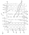
- FIG. 3 shows how an arrangement according to the invention of Containers 21 can be provided in a transport device 1.
- the Containers 21 are as substantially conical section-shaped plastic deep-drawn parts executed with all-round sealing edge 22.
- On the seal edge is a container lid, not shown, for example embossed in the form of an aluminum foil.
- container 21 shown on the right completely on the base 4 of the Transport device 1 rests, all subsequent containers 21 are with their circumferential sealing edge 22 on the previous container 21 put on and get into a slight inclined position.
- the shingled arrangement of the containers 21 according to the invention realized that at the same time to increase the packing density of the Containers 21 leads to the known transport devices and full use of the base edge length, which is matched to the pallet size allowed.
- impressions are provided on the base of the transport device, which favor the inclination of the cups and for a smaller one Ensure load on the container bottoms.
Landscapes
- Engineering & Computer Science (AREA)
- Mechanical Engineering (AREA)
- Packages (AREA)
- Freezing, Cooling And Drying Of Foods (AREA)
- General Preparation And Processing Of Foods (AREA)
Abstract
Description
Die Erfindung betrifft eine Transportvorrichtung für Milchprodukte mit einer im wesentlichen rechteckigen Grundfläche, an der Haltemittel zur Aufnahme mehrerer im wesentlichen gleichförmiger Behälter für die Milchprodukte vorgesehen sind.The invention relates to a transport device for milk products a substantially rectangular base on which holding means for Inclusion of several substantially uniform containers for the Dairy products are provided.
Transportvorrichtungen werden insbesondere zur Lagerung, zum Transport und zur Präsentation von im wesentlichen gleichförmigen Behältern für Milchprodukte eingesetzt. Sie müssen insbesondere Anforderungen im Hinblick auf Formstabilität, geringes Gewicht, niedrige Herstellungskosten und geringen Raumbedarf erfüllen. Diese Anforderungen können insbesondere durch eine aus einem Flachmaterial ausgeschnittene, gefalzte und abschnittsweise flächig verbundene dreidimensionale Struktur mit einer im wesentlichen rechteckigen Grundfläche und einer im Verhältnis zur Grundflächenkantenlänge geringen Höhe verwirklicht werden. Dabei sind in einer zumindest nahezu parallel zur Grundfläche angeordneten Haltefläche Haltemittel zur Aufnahme mehrerer im wesentlichen gleichförmiger Behälter für die Milchprodukte vorgesehen. Die Haltefläche weist eine Mehrzahl von Ausschnitten oder Vertiefungen auf, die an die Geometrie der Behälter angepasst sind und die insbesondere als formschlüssig wirkende Haltemittel für die Aufnahme der Behälter vorgesehen sind. Durch die Transportvorrichtung und die in der Transportvorrichtung eingebrachten Behälter wird ein dreidimensionaler Verbund gebildet, der eine im wesentlichen kubische Hüllgeometrie aufweist. Dadurch ist die Transportvorrichtung mit den Behältern besonders gut für eine Aufeinanderstapelung und damit für Lagerungs-, Transport- und Präsentationszwecke geeignet. Als Milchprodukte, die in den Behältern einer derartigen Transportvorrichtung vorgesehen sind, kommen insbesondere niedrig- bis hochviskose, wässrige bzw. creme- oder gelartige Substanzen wie Schlagsahne, Pudding, Quark, Joghurt, Buttermilch oder Frischkäseprodukte in Frage.Transport devices are used especially for storage, for transportation and for the presentation of substantially uniform containers used for dairy products. You must have particular requirements in terms of dimensional stability, light weight, low manufacturing costs and meet small space requirements. These requirements can in particular by a folded one cut from a flat material and sectionally connected three-dimensional structure with a substantially rectangular base and one in proportion to the base edge length low height can be realized. They are arranged in an at least almost parallel to the base area Holding surface holding means for receiving several essentially uniform container provided for the milk products. The holding area has a plurality of cutouts or indentations the geometry of the containers are adapted and in particular as positively acting holding means are provided for receiving the container are. Through the transport device and in the transport device inserted container becomes a three-dimensional composite formed, which has an essentially cubic envelope geometry. Thereby the transport device with the containers is particularly good for a stack and thus for storage, transport and Suitable for presentation purposes. As dairy products in the containers such a transport device are provided, come in particular low to highly viscous, aqueous, cream or gel-like Substances like whipped cream, pudding, curd cheese, yogurt, buttermilk or Cream cheese products in question.
Die Aufgabe der Erfindung besteht darin, eine Transportvorrichtung der eingangs genannten Art zu schaffen, die einen sicheren Transport und eine hohe Packungsdichte ermöglicht.The object of the invention is to provide a transport device to create a safe transport and enables a high packing density.
Die Erfindung ist dadurch gekennzeichnet, dass für zumindest eine erste Grundflächenkantenlänge ein ganzzahliger Bruchteil einer Europalettenkantenlänge vorgesehen ist. Für eine rationelle und kostengünstige Beförderung der Transportvorrichtungen mit den Behältern für die Milchprodukte werden mehrere Transportvorrichtungen nebeneinander und/oder übereinander auf eine Europalette gelegt. Eine Europalette ist eine insbesondere aus einer Holzlattenkonstruktion aufgebaute, stabile Trägerplattform mit hoher Traglast, die als genormte Unterlage für verschiedenste Güter verwendbar ist. Durch ihre Aufbauweise ermöglicht die Europalette eine Handhabung mit Gabelstablern oder Hubwagen. Dabei ist die Europalette im wesentlichen rechteckig gestaltet und weist nach gegenwärtiger Norm eine längere Europalettenkantenlänge von 1,20m sowie eine kürzere Europalettenkantenlänge von 0,80m auf. Durch eine Anpassung einer ersten Grundflächenkantenlänge der Transportvorrichtung auf eine Europalettenkantenlänge lässt sich eine besonders effektive Flächenausnutzung der Europalette im Hinblick auf die darauf anzuordnenden Transportvorrichtungen erzielen. Dazu ist zumindest eine erste, insbesondere eine längere Grundflächenkantenlänge der Transportvorrichtung entsprechend einem ganzzahligen Bruchteil der Europalettenkantenlänge vorgesehen. Ein ganzzahliger Bruchteil der Europalettenkantenlänge wird gewählt, um dementsprechend eine ganzzahlige Anzahl von Transportvorrichtungen so auf der Europalette unterbringen zu können. Dadurch tritt weder ein nennenswerter Überstand von Transportvorrichtungen über die Europalette auf, noch liegt ein ungenutzter Abstand zwischen einer Außenkante der Transportvorrichtung und der Europalettenkante vor. Während im ersten Fall durch den Überstand von Transportvorrichtungen eine raumökonomische Ordnung von Europaletten insbesondere auf einer Lagerfläche oder Ladefläche verhindert würde, ergäbe sich bei einem ungenutzten Abstand zwischen Außenkante und Europalettenkante eine nur ungenügende Raumausnutzung und damit Nachteile für eine Transportkapazität sowie für eine Stabilität übereinandergestapelter Transportvorrichtungen.The invention is characterized in that for at least a first Base edge length is an integer fraction of a Euro pallet edge length is provided. For efficient and economical transportation transport devices with containers for milk products several transport devices are placed side by side and / or placed on top of each other on a Euro pallet. A Euro pallet is a stable, built in particular from a wooden slat construction Carrier platform with a high load capacity, which is used as a standardized base for various Goods is usable. Made possible by their construction the Euro pallet can be handled with fork lifts or pallet trucks. The Euro pallet is designed essentially rectangular and has a longer Euro pallet edge length of 1.20m and a shorter Euro pallet edge length of 0.80m. By adapting a first base edge length of the Transport device on a Euro pallet edge length can be one particularly effective use of space in the Euro pallet with regard to achieve the transport devices to be arranged thereon. Is to at least a first, in particular a longer base edge length the transport device according to an integer A fraction of the Euro pallet edge length is provided. An integer Fraction of the Euro pallet edge length is chosen to be accordingly an integer number of transport devices so on the To be able to accommodate Euro pallets. As a result, there is no significant Protrusion of transport devices over the euro pallet, there is still an unused distance between an outer edge of the Transport device and the Euro pallet edge in front. While in the first Fall through the protrusion of transport devices a space-saving Organization of euro pallets, especially on a storage area or loading area would be prevented if there was no use The distance between the outer edge and the edge of the Euro pallet is insufficient Space utilization and thus disadvantages for a transport capacity as well as for stability of stacked transport devices.
In Ausgestaltung der Erfindung ist für den ganzteiligen Bruchteil der Europalettenkantenlänge ein Wertebereich von 2-6 vorgesehen. Dadurch ergibt sich für die Grundflächenkantenlänge der Transportvorrichtung bei Bezug auf die längere Europalettenkantenlänge von 1,20m ein Längenbereich von 0,60m-0,20m. Bezogen auf die kürzere Europalettenkantenlänge ergibt sich für die Grundflächenkantenlänge ein Längenbereich von 0,40m-0,133m. In Abhängigkeit von dem gewählten Bruchteil der Europalettenkantenlänge lässt sich dadurch eine Anpassung der Grundflächenkantenlänge der Transportvorrichtung an Erfordernisse von Verpackungsmaschinen, Kühlregalen, Verkaufsdisplays oder anderen für den Vertrieb von Milchprodukten geeigneten und insbesondere in Groß- und Einzelhandelsgeschäften zum Einsatz kommenden Präsentationsmitteln abstimmen. In an embodiment of the invention is for the whole part fraction of the Euro pallet edge length a value range of 2-6 is provided. Thereby results for the base edge length of the transport device at In relation to the longer Euro pallet edge length of 1.20 m, a length range from 0.60m-0.20m. Based on the shorter Euro pallet edge length there is a length range for the base edge length from 0.40m-0.133m. Depending on the fraction chosen Euro pallet edge length can be adjusted to the base edge length the transport device to the requirements of packaging machines, Cooling shelves, sales displays or other for the distribution of dairy products suitable and especially in wholesale and retail stores use presentation tools vote.
In weiterer Ausgestaltung der Erfindung ist für die erste Grundflächenkantenlänge eine halbe Europalettenkantenlänge vorgesehen. Dadurch lässt sich eine besonders wirtschaftliche Verpackungseinheit aus der Transportvorrichtung und der darin aufgenommenen Behälter erzielen. Die Verpackungseinheit beinhaltet einerseits eine große Anzahl von Behältern, andererseits weist sie insbesondere bei Anwendung geeigneter Verstärkungsmaßnahmen eine hohe Stabilität auf und ist auch auf unebenem Untergrund standsicher. Insbesondere bei Zugrundelegung der kürzeren Europalettenkantenlänge als Bezugsmaß für die Grundflächenkantenlänge lässt sich durch den Wert 2 für den ganzzahligen Bruchteil der Europalettenkantenlänge eine vorteilhafte Anordnung von Transportvorrichtungen auf der Europalette erzielen.In a further embodiment of the invention is for the first base edge length half a Euro pallet edge length is provided. Thereby can be a particularly economical packaging unit from the Achieve transport device and the containers accommodated therein. The packaging unit contains on the one hand a large number of containers, on the other hand, especially when used, it points out Reinforcement measures have a high stability and is also on uneven Stable surface. Especially when using the shorter Euro pallet edge length as a reference for the base edge length can be determined by the value 2 for the integer A fraction of the Euro pallet edge length an advantageous arrangement of Achieve transport devices on the Euro pallet.
In weiterer Ausgestaltung der Erfindung ist für die erste Grundflächenkantenlänge 0,39m-0,40m vorgesehen. Innerhalb des Längenbereiches von 0,39m-0,40m für die erste Grundflächenkantenlänge lässt sich eine Transportvorrichtung auch in Massenproduktion und unter Verwendung von kostengünstigen Werkstoffen wie Pappe, Kunststoff, Pressstoff oder geschäumtem Material ohne größeren Aufwand mit einer ausreichenden Präzision herstellen. Als Herstellungsverfahren kommen neben dem Ausstanzen, Falzen und Verbinden insbesondere von Pappzuschnitten auch Tiefzieh- oder Blasform-, Ausschäum- oder Spritzgussverfahren in Frage.In a further embodiment of the invention is for the first base edge length 0.39m-0.40m provided. Within the length range from 0.39m-0.40m for the first base edge length Transport device also in mass production and using of inexpensive materials such as cardboard, plastic, or press foamed material with little effort without major effort Establish precision. In addition to the manufacturing process Punching out, folding and joining in particular cardboard blanks also deep drawing or blow molding, foaming or injection molding in Question.
In weiterer Ausgestaltung der Erfindung ist auch für eine zweite Grundflächenkantenlänge ein ganzzahliger Bruchteil einer Europalettenkantenlänge vorgesehen. In Zusammenwirkung mit der ersten auf die Europalettenkantenlänge abgestimmten Grundflächenkantenlänge lässt sich somit eine besonders vorteilhafte Anpassung der Grundfläche der Transportvorrichtung auf die Europalette verwirklichen. Dadurch kann sichergestellt werden, dass bei einer Anordnung mehrerer Transportvorrichtungen auf der Europalette weder ein Überstand der Transportvorrichtungen über die Europalette noch eine Spaltenbildung zwischen den einzelnen Transportvorrichtungen stattfindet. Eine besonders vorteilhafte Grundfläche der Transportvorrichtung liegt insbesondere dann vor, wenn eine kürzere Grundflächenkantenlänge als ganzzahliger Bruchteil der längeren Europalettenkantenlänge vorgesehen ist.In a further embodiment of the invention is also for a second base edge length an integer fraction of a Euro pallet edge length intended. In cooperation with the first on the Euro pallet edge length coordinated base edge length can be thus a particularly advantageous adjustment of the base of the Realize the transport device on the Euro pallet. This can be ensured that with an arrangement of several transport devices on the euro pallet there is no overhang of the transport devices a gap formation between the individual transport devices takes place. A particularly beneficial one Base area of the transport device is present in particular if a shorter base edge length than an integral fraction of the longer Euro pallet edge length is provided.
In weiterer Ausgestaltung der Erfindung ist für die zweite Grundflächenkantenlänge ein Viertel einer Europalettenkantenlänge vorgesehen. Damit ergibt sich ein Längenbereich für die zweite Grundflächenkantenlänge von 0,29m-0,30m. Vorzugsweise ist ein Sollwert von 0,295m vorgesehen, um fertigungstechnisch bedingte Toleranzen der Transportvorrichtung abfangen zu können.In a further embodiment of the invention is for the second base edge length a quarter of a Euro pallet edge length is provided. This results in a length range for the second base edge length from 0.29m-0.30m. A target value of 0.295 m is preferably provided, manufacturing tolerances of the transport device intercept.
In weiterer Ausgestaltung der Erfindung sind als Haltemittel für die Behälter Ausnehmungen in einer zumindest nahezu parallel zur Grundfläche im Abstand zu dieser angeordneten Haltefläche vorgesehen. Die Ausnehmungen sind vorzugsweise in zueinander parallelen Reihen ausgebildet. Die Ausnehmungen dienen zur Aufnahme der Behälter. Vorzugsweise handelt es sich bei den Behältern, insbesondere Bechern, um solche mit kreisrundem Querschnitt. Die Ausnehmungen sind in Form und/oder Größe vorzugsweise entsprechend angepasst, insbesondere ebenfalls im wesentlichen kreisrund. Die Behälter stehen dabei mit einem Behälterboden auf der Grundfläche der Transportvorrichtung auf und werden somit im wesentlichen orthogonal zu einer Haupterstreckung der Grundfläche gehalten. Für eine formschlüssige Halterung der Behälter parallel zur Haupterstreckung der Grundfläche sind die Ausnehmungen, insbesondere Einschnitte oder Austanzungen, in einer der Querschnittsform der Behälter in etwa entsprechenden Form vorgesehen. Durch diese Ausnehmungen in der Haltefläche können durch die Haltefläche Haltekräfte auf jeden der Behälter ausgeübt werden, die sich im wesentlichen parallel zur Haupterstreckung der Grundfläche auswirken. In Zusammenwirkung mit der Grundfläche der Transportvorrichtung kann durch eine den Behältern anhaftende Gewichtskraft eine sichere Aufbewahrung der Behälter in der Transportvorrichtung in nahezu alle Raumrichtungen gewährleistet werden. Lediglich in Richtung einer Flächennormalen der Grundfläche, die sich in Richtung der Haltefläche bzw. bei normaler Lage entgegen der Gewichtskraft der Behälter erstreckt, weist die Transportvorrichtung bei bevorzugten Ausführungsformen keine Zusatzmittel zur Ausübung von Haltekräfte auf die Behälter auf. Als Zusatzmittel für Haltekräfte in dieser Raumrichtung könnten, was nicht erforderlich ist, formschlüssig mit den Behältern wechselwirkende Laschen oder Haltebügel in Frage kommen.In a further embodiment of the invention are as holding means for the container Recesses in an at least almost parallel to the base provided at a distance from this arranged holding surface. The Recesses are preferably in rows parallel to each other educated. The recesses serve to hold the container. The containers, in particular cups, are preferably around those with a circular cross-section. The recesses are in Shape and / or size preferably adapted accordingly, in particular also essentially circular. The containers are there with a container bottom on the base of the transport device and thus become essentially orthogonal to a main extension the base area. For a positive mounting of the Containers parallel to the main extent of the base are the recesses, especially cuts or cuts in one of the Cross-sectional shape of the container provided in approximately the corresponding shape. Through these recesses in the holding surface can by Holding surface holding forces are exerted on each of the containers that are affect essentially parallel to the main extent of the base. In cooperation with the base of the transport device can be secured by a weight attached to the containers Storage of the containers in the transport device in almost all Spatial directions are guaranteed. Only in the direction of a surface normal the base area, which is towards the holding area or in a normal position extends against the weight of the container, has the transport device in preferred embodiments no additives to exert holding forces on the containers on. As an additive for holding forces in this spatial direction, what is not required, form-fittingly interacting with the containers Brackets or brackets come into question.
Bei einer besonders bevorzugten Ausführungsform der Erfindung ist mindestens eine, insbesondere eine, Grundflächenkantenlänge kürzer als eine Reihenlänge, die sich aus einer Aneinanderreihung der auf der Grundflächenkantenlänge untergebrachten Behälter ergibt, ohne dass die Behälter an den Rändern der Transportvorrichtung überstehen. Vorzugsweise ist die Grundflächenkantenlänge um mindestens 2,5%, insbesondere mindestens 3%, kürzer. In der Regel ist sie 3 bis 5% kürzer. Dies erlaubt eine optimale Platzausnutzung.In a particularly preferred embodiment of the invention at least one, in particular one, base edge length is shorter as a row length, which results from a sequence of the on the Base edge length accommodated container results without the containers protrude at the edges of the transport device. Preferably is the base edge length by at least 2.5%, especially at least 3%, shorter. As a rule, it is 3 to 5% shorter. This allows an optimal use of space.
In weiterer Ausgestaltung der Erfindung ist für die Ausnehmungen der Haltmittel eine Beabstandung vorgesehen, die kleiner als ein maximales Projektionsmaß eines Behälters auf die Grundfläche ist. Ein Projektionsmaß des Behälters ergibt sich durch Projektion eines Behälterquerschnittes bei korrekt in Transportvorrichtung aufgenommenem Behälter auf die Grundfläche der Transportvorrichtung. Diese Ausgestaltung eignet sich besonders für die bekannten Behälter für Milchprodukte, die an der Oberseite eine größere Flächenausdehnung haben als an ihrer Unterseite. Solche Behälter besitzen insbesondere eine konische Form und/oder an der Oberseite einen nach außen überstehenden Rand. Der Abstand zwischen Grundfläche und Haltefläche ist insbesondere kleiner als die Höhe der Behälter. Während bei bekannten Transportvorrichtungen die Ausnehmungen der Haltemittel derartig beabstandet sind, dass ein maximales Projektionsmaß des Behälters als Mindestabstand zwischen den Ausnehmungen vorgesehen ist, wird bei der erfindungsgemäßen Transportvorrichtung eine Reduzierung der Beabstandung vorgesehen. Dadurch kann auf einer identischen Grundfläche eine größere Anzahl von Behältern untergebracht werden, sofern diese in geeigneter Weise zueinander angeordnet sind. Für eine geeignete Anordnung kommt insbesondere bei gleichförmigen Behältern ein Höhenversatz der Behälter zueinander in Frage, um ein gegenseitiges Durchdringen und eine dadurch auftretende Beschädigung der Behälter untereinander zu vermeiden.In a further embodiment of the invention is for the recesses Holding means provided a spacing that is less than a maximum Projection dimension of a container on the base is. A projection measure of the container results from the projection of a container cross section with the container correctly accommodated in the transport device on the base of the transport device. This configuration is suitable are particularly well-known for the containers for dairy products that have a larger surface area on the upper side than on its underside. Such containers have in particular a conical shape and / or an outwardly projecting edge on the top. The The distance between the base surface and the holding surface is in particular smaller than the height of the container. While in known transport devices the recesses of the holding means are spaced such that a maximum projection dimension of the container as a minimum distance between the recesses is provided in the invention Transport device provided a reduction in the spacing. This allows a larger one on an identical area Number of containers can be accommodated, provided these are suitable Are arranged to each other. For a suitable arrangement there is a height offset, particularly in the case of uniform containers Containers in question to each other to ensure mutual penetration and any damage to the containers that occurs as a result avoid.
In weiterer Ausgestaltung der Erfindung sind in der Transportvorrichtung Behälter vorgesehen, die an ihrer Oberseite eine zumindest teilweise umlaufenden, seitlich überstehenden Siegelrand aufweisen, wobei die Behälter zumindest längs einer Grundflächenkante mit den Siegelrändern überlappend angeordnet sind. Dabei werden insbesondere kegelabschnittsförmig, zylindrisch, polygon- oder polygonkegelförmig geformte, flüssigkeitsdichte Behälter aus Materialien wie Kunststoff, beschichteter Pappe oder Verbundmaterialien eingesetzt. Die Behälter weisen insbesondere an einer nahe einem maximalen Behälterquerschnitt vorgesehenen Behälteröffnung einen zumindest nahezu umlaufenden, nach außen auskragenden dünnwandigen Siegelrand auf. An diesem Siegelrand kann die Behälteröffnung mit einem insbesondere aus Kunststoff- oder Aluminiumfolie hergestellten Behälterdeckel verschlossen sein. Durch eine Überlappung der Siegelränder der Behälter kann die Beabstandung der Ausnehmungen der Haltemittel kleiner als das maximale Projektionsmaß der Behälter gewählt werden ohne dass die Behälter durch mechanischen Kontakt beschädigt werden. Bei einer bevorzugten Anordnung der Behälter sind die Siegelränder insbesondere geschuppt angeordnet, dabei liegt jeweils ein nachfolgender Behälter mit seinem Siegelrand auf einem Siegelrand eines vorhergehenden Behälters auf. In einer besonders bevorzugten Ausführungsform der Erfindung sind an der Grundfläche entsprechende Einprägungen oder anders geartete Unterstützungsmittel für die Behälter vorgesehen. Dadurch wird eine treppenartige oder geschuppte Anordnung der Behälter unterstützt und gleichzeitig eine gleichmäßige Belastung der Behälterböden erreicht. Weiterhin kann durch eine derartige Anordnung ein Kontakt der jeweils benachbarten Siegelränder vermieden werden, was insbesondere bei empfindlichen Behälterdeckeln oder langen und rauhen Transportwegen eine Erhöhung einer Transportsicherheit und Transportstabilität der Behälter in der Transportvorrichtung ermöglicht.In a further embodiment of the invention are in the transport device Containers provided at least partially on their top have circumferential, laterally protruding seal edge, the Containers at least along a base edge with the sealing edges are arranged overlapping. In particular, cylindrical, polygonal or polygonal cone-shaped, liquid-tight container made of materials such as plastic, coated Cardboard or composite materials used. The containers have in particular provided at a near a maximum container cross section Container opening an at least almost circumferential, after cantilevered thin-walled sealing edge on the outside. On this seal edge can the container opening with a plastic or aluminum foil produced container lid may be closed. The container can be overlapped by an overlap Spacing of the recesses of the holding means is smaller than the maximum Projection size of the container can be chosen without the container can be damaged by mechanical contact. In a preferred one Arrangement of the containers, the sealing edges are scaled in particular arranged, each with a subsequent container its seal edge on a seal edge of a previous container on. In a particularly preferred embodiment of the invention are corresponding impressions or other types on the base Support means are provided for the containers. This will supports a stair-like or scaled arrangement of the containers and at the same time achieves an even load on the container bottoms. Furthermore, such an arrangement can contact the neighboring sealing edges can be avoided, which in particular with sensitive container lids or long and rough transport routes an increase in transport safety and stability the container in the transport device enables.
In weiterer Ausgestaltung der Erfindung sind die Behälter vorzugsweise im wesentlichen konisch ausgebildete Becher, die über die Haltefläche überstehen. Dabei ist eine Bechergeometrie so gewählt, dass eine nach oben weisende Becheröffnung mit einem umlaufenden Siegelrand versehen ist und der Becher ausgehend von der Becheröffnung als Kegelabschnitt mit zu einem Becherboden hin abnehmenden Querschnitt versehen ist. Wird ein derartiger Becher in die Transportvorrichtung gestellt, ragt er zumindest abschnittsweise über die als Oberkante der Transportvorrichtung ausgebildete Haltefläche hinaus und kann dadurch insbesondere von geeigneten Transportgreifern in die Transportvorrichtung abgesetzt und durch Kunden bequem gegriffen werden.In a further embodiment of the invention, the containers are preferred essentially conical cups over the holding surface survive. A cup geometry is selected so that one after The cup opening at the top has a circumferential seal edge and the cup starting from the cup opening as a cone section provided with a decreasing cross-section towards a cup bottom is. If such a cup is placed in the transport device, it projects at least in sections over the top edge of the transport device trained holding surface and can in particular of suitable transport grippers in the transport device discontinued and easily gripped by customers.
In weiterer Ausgestaltung der Erfindung weisen die Becher ein Fassungsvermögen in einem Bereich von 0,16 Liter bis 0,3 Liter, bevorzugt in einem Bereich zwischen 0,2 Liter und 0,25 Liter auf. Damit kann ein besonders vorteilhaftes Verhältnis zwischen der Größe der Transporteinrichtung, der Menge des in den Bechern aufgenommenen Milchproduktes und der Standfestigkeit der Becher in der Transporteinrichtung verwirklicht werden. Durch die vorteilhafte Standfestigkeit der einzelnen Becher in der Transporteinrichtung wird auch die Stabilität mehrerer, übereinander gestapelter und mit Bechern versehener Transporteinrichtungen vorteilhaft beeinflusst, was sich insbesondere in einer verbesserten Handhabung einer mit gestapelten Transporteinrichtungen versehenen Europalette äußert.In a further embodiment of the invention, the cups have a capacity in a range of 0.16 liters to 0.3 liters, preferred in a range between 0.2 liters and 0.25 liters. With that a particularly advantageous ratio between the size of the transport device, the amount of milk product in the cups and the stability of the cups in the transport device be realized. Due to the advantageous stability of the individual Cups in the transport device will also increase the stability of several transport devices stacked on top of one another and provided with cups advantageously influenced, which is particularly reflected in an improved Handling a stacked transport device Euro pallet expresses.
In weiterer Ausgestaltung der Erfindung sind längs der ersten Grundflächenkantenlänge
6 benachbarte, im wesentlichen äquidistante Ausnehmungen
als Haltemittel vorgesehen. Damit lassen sich in der Transportvorrichtung
längs der ersten Grundflächenkantenlänge 6 Behälter, insbesondere
in geschuppter Anordnung unterbringen. Durch die im wesentlichen
äquidistant angeordneten Ausnehmungen sind während des
Transports auftretende Belastungen nahezu gleichförmig auf die 6 hintereinander
angeordneten Becher verteilt und führen daher auch zu einer
homogenen Kraftverteilung.In a further embodiment of the invention are along the first
In weiterer Ausgestaltung der Erfindung sind längs der zweiten Grundflächenkantenlänge 4 benachbarte zumindest nahezu äquidistante Ausnehmungen vorgesehen. Damit ergeben sich für eine erfindungsgemäße Transportvorrichtung 24 Ausnehmungen, in die Behälter gestellt werden können. Abhängig von einer Beabstandung längs der zweiten Grundflächenkantenlänge kann auch für die 4 benachbarten Behälter eine insbesondere geschuppte Anordnung vorgesehen sein.In a further embodiment of the invention are along the second base edge length 4 adjacent at least almost equidistant recesses intended. This results in an inventive Transport device 24 recesses into which containers are placed can. Depending on a spacing along the second base edge length can also be a particular one for the 4 neighboring containers shingled arrangement may be provided.
In weiterer Ausgestaltung der Erfindung sind Mittelachsen der Ausnehmungen weniger als 75mm voneinander beabstandet, wobei der maximale Durchmesser der Behälter im oberen Bereich mehr als 65mm beträgt. Eine Mittelachse einer Ausnehmung wird durch eine in Flächennormalenrichtung der Haltefläche erstreckte und auf einem Flächenmittelpunkt der Ausnehmung angeordnete Flächenzentrumsachse gebildet. Demgegenüber beträgt ein maximaler Durchmesser der Behälter im oberen Bereich nahe der Behälteröffnung, insbesondere am oberen Siegelrand mehr als 65mm, insbesondere 68mm. Durch eine Beabstandung der Mittelachsen der Ausnehmungen von insbesondere 65mm, besonders bevorzugt 64mm lässt sich die vorab beschriebene geschuppte Anordnung der Behälter in der Transportvorrichtung in einfacher Weise verwirklichen. Damit können in der Transportvorrichtung 24 Becher mit einem Außendurchmesser von insbesondere 68mm auf einer Grundfläche von maximal 0,4m mal 0,3m aufgenommen werden. Es kann gegenüber den aus dem Stand der Technik bekannten Transportvorrichtungen, die insbesondere exakt auf einen maximalen Querschnitt der Behälter angepasst sind und eine minimale Grundfläche einnehmen, bei einer nur geringfügigen Vergrößerung der Grundfläche eine signifikante, insbesondere 20-prozentige Erhöhung der Behälteranzahl bezogen auf eine Transportvorrichtung realisiert werden. Die erfindungsgemäße Transportvorrichtung erfüllt Anforderungen im Hinblick auf den raumökonomischen Transport auf Paletten und die Lagerung von Milchprodukten in Transportvorrichtungen in Verkaufsregalen besonders vorteilhaft.In a further embodiment of the invention, central axes of the recesses are spaced less than 75mm apart, the maximum The diameter of the container in the upper area is more than 65mm. A central axis of a recess is defined by a normal to the surface the holding surface and on a surface center arranged surface center axis of the recess. In contrast, the maximum diameter of the container in the upper Area near the container opening, especially at the top of the seal more than 65mm, especially 68mm. By spacing the central axes of the recesses, in particular 65 mm, 64 mm can be scaled particularly preferably Arrangement of the containers in the transport device in simple Realize wise. In this way, in the transport device 24 Cups with an outside diameter of 68mm in particular on one Footprint of maximum 0.4m by 0.3m. It compared to the transport devices known from the prior art, which in particular exactly to a maximum cross section the containers are adapted and take up a minimal footprint, with only a slight increase in the base area, a significant, in particular related to a 20 percent increase in the number of containers be realized on a transport device. The invention Transport device meets requirements with regard to the space-saving transport on pallets and the storage of dairy products particularly advantageous in transport devices on store shelves.
Weitere Vorteile und Merkmale ergeben sich aus den Ansprüchen sowie aus der Beschreibung von bevorzugten Ausführungsbeispielen der Erfindung, das anhand der Zeichnungen beschrieben ist.
- Figur 1
- zeigt in ebener Darstellung einen flächigen Zuschnitt für eine Transportvorrichtung,
- Figur 2
- in isometrischer Darstellung einen Eckausschnitt einer benutzungsfertigen Transportvorrichtung,
Figur 3- in ebener Schnittdarstellung eine Transportvorrichtung mit Behältern.
- Figure 1
- shows a planar cut for a transport device,
- Figure 2
- an isometric view of a corner section of a ready-to-use transport device,
- Figure 3
- in a flat sectional view a transport device with containers.
Bei dem in Figur 1 dargestellten Zuschnitt 2 einer Transportvorrichtung 1 handelt es sich um einen ausgestanzten und mit Falzkanten versehenen Pappkarton. Aus diesem Zuschnitt 2 wird in einem nachfolgenden, nicht dargestelltem Arbeitsschritt durch Falzvorgänge und Verklebung eine dreidimensionale Struktur hergestellt, wie sie in Figur 2 auschnittsweise dargestellt ist. Dazu ist in dem Zuschnitt 2 eine Vielzahl von Ausstanzungen, Ausklinkungen und Einschnitten vorgesehen, die für verschiedene Funktionen der Transportvorrichtung benötigt werden.In the blank 2 of a transport device 1 shown in FIG. 1 it is a punched out and provided with folded edges Cardboard box. This blank 2 will not be used in a subsequent one illustrated work step by folding and gluing one three-dimensional structure, as shown in Figure 2 cut-out is shown. For this purpose, a large number of punched-out sections are in the blank 2, Notches and cuts provided for different Functions of the transport device are required.
Der Zuschnitt 2 weist eine im wesentlichen rechteckige Grundfläche 4
auf. An von einander abgewandten kürzeren Seitenkanten der Grundfläche
4 sind über Querfalzkanten 5 verbundene Querlaschen 7 vorgesehen.
An Längsseiten der Grundfläche 4 sind über Längsfalzkanten verbundene
Seitenflächen 8 vorgesehen, an denen jeweils über parallel zu
den Längsfalzkanten 6 verlaufende Halteflächenfalzkanten 9 vorgesehene
Halteflächenabschnitte 10 angebracht sind. Die Halteflächeabschnitte
10 weisen Halteausnehmungen 3 auf, wobei jeweils der Grundfläche
4 zugewandte Halteausnehmungen 3 eine Kreiskontur 11 aufweisen,
während einer Zuschnittsaußenkante 13 benachbarte Halteausnehmungen
3 als Schwalbenschwanzkonturen 12 vorgesehen sind. Die
Schwalbenschwanzkreiskonturen 12 weisen jeweils einen der Zuschnittsaußenkante
13 zugewandten Seitenfalz auf, der eine Verbindung
zwischen dem Halteflächenabschnitt 10 und Verstärkungslaschen 14
darstellt. Die Verstärkungslaschen 14 entsprechen nahezu vollständig
der Schwalbenschwanzkreiskontur 12, sind jedoch an einer der Grundfläche
4 zugewandten Stirnseite geradlinig geschnitten, wobei die Stirnseite
parallel zu der Längsfalzkante 6 angeordnet ist. An den Seitenflächen
8 sind jeweils mehrere Kühlöffnungen 19 vorgesehen, während an
der Grundfläche 4 Zirkulationsöffnungen 17 sowie Transportöffnungen
18 vorgesehen sind. Mittig auf der Grundfläche 4 und parallel zur Längsfalzkante
6 sind paarige Klebelaschen 19 vorgesehen, die mit der
Grundfläche 4 über jeweils in Richtung der Längsfalzkante 6 weisende
Klappfalze 20 verbunden sind. Weiterhin sind jeweils an den Stirnseiten
der Seitenflächen 8 sowie der Halteflächenabschnitte 10 nicht näher bezeichnete
Klebelaschen vorgesehen, die für eine Verklebung beim Überführen
des Zuschnitts in die dreidimensionale Struktur dienen.The blank 2 has an essentially rectangular base area 4
on. On shorter side edges of the base facing away from one another
4
Für die Herstellung der als dreidimensionale Struktur ausgebildeten
Transportvorrichtung aus dem Zuschnitt 2 werden in einem Schritt die
Seitenflächen 8 um die Längsfalzkanten 6 in einen Winkel von 90° zur
Grundfläche 4 gebracht. Weiterhin werden die Querlaschen 7 und die
Querfalzkanten 5 ebenfalls um 90° gegenüber der Grundfläche 4 gleichsinnig
mit den Seitenkanten abgewinkelt. In einem weiteren, insbesondere
nachfolgenden Schritt werden die an den Stirnseiten der Seitenflächen
8 vorgesehenen Klebelaschen um 90° gegenüber den Seitenflächen
8 abgewinkelt und in Kontakt mit den Querlaschen 7 gebracht, wobei
eine Verklebung zwischen Klebelaschen und Querlaschen 7 vorgenommen
wird. Die Halteflächenabschnitte 10 werden so um die Halteflächenfalzkanten
9 abgewinkelt, dass beide Halteflächenabschnitte 10 eine
gemeinsame Ebene einnehmen. Die nicht näher bezeichneten Klebelaschen
der Halteflächenabschnitte 10 werden an den Querlaschen 7
angeklebt. Dabei kann durch nicht näher bezeichnete Öffnungen in der
Grundfläche 4, die den Querfalzkanten 5 benachbart sind, eine mechanische
Abstützung von innen gegen die Querlaschen 7 vorgenommen
werden, um auftretende Andruckkräfte auf die Klebelaschen kompensieren
zu können. Die Verstärkungslaschen 14 werden um die Seitenfalze
15 von den Halteflächenabschnitten 10 in Richtung der Grundfläche 4
abgeklappt und mit den aus der Grundfläche 4 in Richtung Halteflächenabschnitte
10 ausgeklappten Klebelaschen 19 verbunden. Nach
Aushärtung des Klebstoffes ergibt sich dadurch die gewünschte formstabile,
leichtgewichtige und kostengünstig herzustellende Transportvorrichtung.For the production of the three-dimensional structure
Transport device from the blank 2 in one step
Side surfaces 8 around the longitudinal fold edges 6 at an angle of 90 ° to
Base area 4 brought. Furthermore, the
In Figur 2 ist ein Ausschnitt aus einer Transportvorrichtung isometrisch
dargestellt, bei dem eine Verstärkungswirkung der Verstärkungslaschen
14 mit den Klebelaschen 19 erkennbar ist. Dadurch wird eine deutliche
Erhöhung einer Biegesteifigkeit der Transportvorrichtung erzielt. Weiterhin
ist erkennbar, wie die nicht näher bezeichneten Klebelaschen, die an
den Halteflächenabschnitten 10 sowie den Seitenflächen 8 vorgesehen
sind, miteinander verbunden werden, um eine besonders stabile Transportvorrichtung
zu gewährleisten. Darüber hinaus wird in Figur 2 dargestellt,
dass sich durch einen nicht näher bezeichneten Überstand der
Klebelaschen der Seitenflächen 8 jeweils eine Eckfahne ausbilden lässt,
die einerseits für eine Stapelung der Transportvorrichtungen ohne Behälter
geeignet ist und andererseits als Abstandshalter zwischen einzelnen
Transportvorrichtungen einsetzbar ist.A section of a transport device is isometric in FIG
shown, in which a reinforcing effect of the reinforcing
In Figur 3 ist dargestellt, wie eine erfindungsgemäße Anordnung von
Behältern 21 in einer Transportvorrichtung 1 vorgesehen sein kann. Die
Behälter 21 sind als im wesentlichen kegelabschnittsförmige Kunststofftiefziehteile
mit umlaufenden Siegelrand 22 ausgeführt. Auf den Siegelrand
ist jeweils ein nicht näher dargestellter Behälterdeckel zum Beispiel
in Form einer Aluminiumfolie aufgeprägt. Während ein erster, in Figur 3
rechts dargestellter Behälter 21 vollständig auf der Grundfläche 4 der
Transportvorrichtung 1 aufliegt, sind alle nachfolgenden Behälter 21 mit
ihrem umlaufenden Siegelrand 22 auf dem jeweils vorhergehenden Behälter
21 aufgelegt und geraten dadurch in eine leichte Schräglage. Dadurch
ist die erfindungsgemäße geschuppte Anordnung der Behälter 21
verwirklicht, die gleichzeitig zu einer Erhöhung der Packungsdichte der
Behälter 21 gegenüber den bekannten Transportvorrichtungen führt und
eine volle Ausnutzung der auf die Palettengröße abgestimmten Grundflächenkantenlänge
erlaubt.FIG. 3 shows how an arrangement according to the invention of
Bei einer nicht näher dargestellten Ausführungsform der Erfindung sind an der Grundfläche der Transportvorrichtung Einprägungen vorgesehen, die die Schrägstellung der Becher begünstigen und für eine geringere Belastung der Behälterböden sorgen.Are in an embodiment of the invention, not shown impressions are provided on the base of the transport device, which favor the inclination of the cups and for a smaller one Ensure load on the container bottoms.
Claims (14)
Applications Claiming Priority (2)
| Application Number | Priority Date | Filing Date | Title |
|---|---|---|---|
| DE20308183U | 2003-05-16 | ||
| DE20308183U DE20308183U1 (en) | 2003-05-16 | 2003-05-16 | Transport device for milk products |
Publications (2)
| Publication Number | Publication Date |
|---|---|
| EP1477422A1 true EP1477422A1 (en) | 2004-11-17 |
| EP1477422B1 EP1477422B1 (en) | 2009-01-14 |
Family
ID=27675456
Family Applications (1)
| Application Number | Title | Priority Date | Filing Date |
|---|---|---|---|
| EP04011486A Expired - Lifetime EP1477422B1 (en) | 2003-05-16 | 2004-05-14 | Tray for dairy products |
Country Status (4)
| Country | Link |
|---|---|
| EP (1) | EP1477422B1 (en) |
| AT (1) | ATE420826T1 (en) |
| DE (2) | DE20308183U1 (en) |
| ES (1) | ES2320215T3 (en) |
Cited By (1)
| Publication number | Priority date | Publication date | Assignee | Title |
|---|---|---|---|---|
| WO2012071009A1 (en) * | 2010-11-25 | 2012-05-31 | Robotgrader Aktiebolag | A method of and system for grading |
Citations (4)
| Publication number | Priority date | Publication date | Assignee | Title |
|---|---|---|---|---|
| AU6280180A (en) * | 1979-09-28 | 1982-04-01 | Peters Ice Cream (W.A.) Ltd. | Packing tubs in cartons |
| EP0316890A2 (en) * | 1987-11-20 | 1989-05-24 | Europa Carton Aktiengesellschaft | Prefolded blank of one piece made of pliable material for a cup-tray |
| DE4418425A1 (en) * | 1993-07-19 | 1995-01-26 | Wez Kunststoff | Stackable plastic container for receiving conical plastic pots, in particular yoghurt pots |
| FR2777549A1 (en) * | 1998-04-20 | 1999-10-22 | Smurfit Socar Sa | Packaging system for batched containers arranged in wrapped layers in trays |
Family Cites Families (4)
| Publication number | Priority date | Publication date | Assignee | Title |
|---|---|---|---|---|
| DE7304684U (en) | 1973-02-08 | 1973-05-30 | Kunststoffwerk Philippine Gmbh & Co Kg | Pallet for transporting vessels, especially for transporting flower pots |
| DE7915373U1 (en) | 1979-05-28 | 1979-09-06 | Grethe Kunststoff Gmbh | Pallet for potted plants |
| GB8601442D0 (en) | 1986-01-22 | 1986-02-26 | Mead Corp | Moulded pallet |
| DE9209188U1 (en) | 1992-07-09 | 1992-10-15 | Polyplast-Sander GmbH, 8503 Altdorf | Stackable transport container |
-
2003
- 2003-05-16 DE DE20308183U patent/DE20308183U1/en not_active Expired - Lifetime
-
2004
- 2004-05-14 DE DE502004008854T patent/DE502004008854D1/en not_active Expired - Lifetime
- 2004-05-14 AT AT04011486T patent/ATE420826T1/en active
- 2004-05-14 EP EP04011486A patent/EP1477422B1/en not_active Expired - Lifetime
- 2004-05-14 ES ES04011486T patent/ES2320215T3/en not_active Expired - Lifetime
Patent Citations (4)
| Publication number | Priority date | Publication date | Assignee | Title |
|---|---|---|---|---|
| AU6280180A (en) * | 1979-09-28 | 1982-04-01 | Peters Ice Cream (W.A.) Ltd. | Packing tubs in cartons |
| EP0316890A2 (en) * | 1987-11-20 | 1989-05-24 | Europa Carton Aktiengesellschaft | Prefolded blank of one piece made of pliable material for a cup-tray |
| DE4418425A1 (en) * | 1993-07-19 | 1995-01-26 | Wez Kunststoff | Stackable plastic container for receiving conical plastic pots, in particular yoghurt pots |
| FR2777549A1 (en) * | 1998-04-20 | 1999-10-22 | Smurfit Socar Sa | Packaging system for batched containers arranged in wrapped layers in trays |
Cited By (1)
| Publication number | Priority date | Publication date | Assignee | Title |
|---|---|---|---|---|
| WO2012071009A1 (en) * | 2010-11-25 | 2012-05-31 | Robotgrader Aktiebolag | A method of and system for grading |
Also Published As
| Publication number | Publication date |
|---|---|
| ES2320215T3 (en) | 2009-05-20 |
| DE502004008854D1 (en) | 2009-03-05 |
| DE20308183U1 (en) | 2003-07-31 |
| ATE420826T1 (en) | 2009-01-15 |
| EP1477422B1 (en) | 2009-01-14 |
Similar Documents
| Publication | Publication Date | Title |
|---|---|---|
| EP0505367B1 (en) | Cardboard tray for cylindrical packages | |
| EP2028115B1 (en) | Presentation container, blank and method for its manufacture | |
| EP3027520A1 (en) | Blank, method for producing an external packaging unit, and packaging system | |
| EP1971526B1 (en) | Apparatus made from foldable flat material for forming compartments for receiving containers, blank for this purpose and packaging | |
| EP0976660B1 (en) | Package for a group of articles and process for its manufacture | |
| DE69125287T2 (en) | METHOD FOR PRODUCING A BOX WITH INTEGRATED CORNER REINFORCEMENTS | |
| EP1477422A1 (en) | Tray for dairy products | |
| DE7528783U (en) | Stackable container | |
| DE69602282T2 (en) | PALLETIZING SYSTEM WITH STRIP-SHAPED REINFORCEMENTS AGAINST PRESSURE FORCES | |
| DE102018119989B4 (en) | Stackable packaging container and system of packaging containers | |
| AT522769B1 (en) | FOLDING BOX | |
| EP3186161B1 (en) | Container erected from a blank | |
| EP4177178B1 (en) | Sorting insert with partition and stacking lug | |
| EP0357906A1 (en) | Device for supplying blanks to a packaging machine | |
| DE29908663U1 (en) | Two-part packaging made of foldable material for packaging individual goods | |
| DE69908490T2 (en) | A system for storing groups of stacked, stacked, flanged containers in a tray made of semi-rigid material | |
| WO2002085742A1 (en) | Packaging arrangement for containers minimising packaging materials and transport volumes and method for production thereof | |
| DE20318053U1 (en) | Packaging for transporting breakable objects, especially wine bottles, comprises a packaging element and a second packaging element which are inserted inside each other to form three separate compartments for the breakable objects | |
| EP3064442B1 (en) | Foldable packaging container and blank for a foldable packaging container | |
| AT406666B (en) | STACKABLE BOX | |
| DE2818888A1 (en) | Three bottle insert for bottle carton - has outer pockets tapered in opposite direction to middle pockets, end bent round | |
| DE102014011624B4 (en) | Packaging and cutting for it | |
| EP3858752A1 (en) | Packaging | |
| DE2641969A1 (en) | Tray for fruit and vegetables - is formed of cardboard with double thickness sides and plastics inner lining | |
| DE10028588B4 (en) | Stackable transport container for stackable cargo |
Legal Events
| Date | Code | Title | Description |
|---|---|---|---|
| PUAI | Public reference made under article 153(3) epc to a published international application that has entered the european phase |
Free format text: ORIGINAL CODE: 0009012 |
|
| AK | Designated contracting states |
Kind code of ref document: A1 Designated state(s): AT BE BG CH CY CZ DE DK EE ES FI FR GB GR HU IE IT LI LU MC NL PL PT RO SE SI SK TR |
|
| AX | Request for extension of the european patent |
Extension state: AL HR LT LV MK |
|
| 17P | Request for examination filed |
Effective date: 20050513 |
|
| AKX | Designation fees paid |
Designated state(s): AT BE BG CH CY CZ DE DK EE ES FI FR GB GR HU IE IT LI LU MC NL PL PT RO SE SI SK TR |
|
| RAP1 | Party data changed (applicant data changed or rights of an application transferred) |
Owner name: CAMPINA GMBH |
|
| GRAP | Despatch of communication of intention to grant a patent |
Free format text: ORIGINAL CODE: EPIDOSNIGR1 |
|
| RIN1 | Information on inventor provided before grant (corrected) |
Inventor name: HUBINGER, KONRAD |
|
| GRAS | Grant fee paid |
Free format text: ORIGINAL CODE: EPIDOSNIGR3 |
|
| GRAA | (expected) grant |
Free format text: ORIGINAL CODE: 0009210 |
|
| AK | Designated contracting states |
Kind code of ref document: B1 Designated state(s): AT BE BG CH CY CZ DE DK EE ES FI FR GB GR HU IE IT LI LU MC NL PL PT RO SE SI SK TR |
|
| REG | Reference to a national code |
Ref country code: GB Ref legal event code: FG4D Free format text: NOT ENGLISH |
|
| REG | Reference to a national code |
Ref country code: CH Ref legal event code: EP |
|
| REG | Reference to a national code |
Ref country code: IE Ref legal event code: FG4D Free format text: LANGUAGE OF EP DOCUMENT: GERMAN |
|
| REF | Corresponds to: |
Ref document number: 502004008854 Country of ref document: DE Date of ref document: 20090305 Kind code of ref document: P |
|
| REG | Reference to a national code |
Ref country code: ES Ref legal event code: FG2A Ref document number: 2320215 Country of ref document: ES Kind code of ref document: T3 |
|
| PG25 | Lapsed in a contracting state [announced via postgrant information from national office to epo] |
Ref country code: SI Free format text: LAPSE BECAUSE OF FAILURE TO SUBMIT A TRANSLATION OF THE DESCRIPTION OR TO PAY THE FEE WITHIN THE PRESCRIBED TIME-LIMIT Effective date: 20090114 Ref country code: FI Free format text: LAPSE BECAUSE OF FAILURE TO SUBMIT A TRANSLATION OF THE DESCRIPTION OR TO PAY THE FEE WITHIN THE PRESCRIBED TIME-LIMIT Effective date: 20090114 |
|
| REG | Reference to a national code |
Ref country code: IE Ref legal event code: FD4D |
|
| PG25 | Lapsed in a contracting state [announced via postgrant information from national office to epo] |
Ref country code: SE Free format text: LAPSE BECAUSE OF FAILURE TO SUBMIT A TRANSLATION OF THE DESCRIPTION OR TO PAY THE FEE WITHIN THE PRESCRIBED TIME-LIMIT Effective date: 20090414 Ref country code: PL Free format text: LAPSE BECAUSE OF FAILURE TO SUBMIT A TRANSLATION OF THE DESCRIPTION OR TO PAY THE FEE WITHIN THE PRESCRIBED TIME-LIMIT Effective date: 20090114 Ref country code: PT Free format text: LAPSE BECAUSE OF FAILURE TO SUBMIT A TRANSLATION OF THE DESCRIPTION OR TO PAY THE FEE WITHIN THE PRESCRIBED TIME-LIMIT Effective date: 20090615 |
|
| PG25 | Lapsed in a contracting state [announced via postgrant information from national office to epo] |
Ref country code: CZ Free format text: LAPSE BECAUSE OF FAILURE TO SUBMIT A TRANSLATION OF THE DESCRIPTION OR TO PAY THE FEE WITHIN THE PRESCRIBED TIME-LIMIT Effective date: 20090114 Ref country code: DK Free format text: LAPSE BECAUSE OF FAILURE TO SUBMIT A TRANSLATION OF THE DESCRIPTION OR TO PAY THE FEE WITHIN THE PRESCRIBED TIME-LIMIT Effective date: 20090114 Ref country code: IE Free format text: LAPSE BECAUSE OF FAILURE TO SUBMIT A TRANSLATION OF THE DESCRIPTION OR TO PAY THE FEE WITHIN THE PRESCRIBED TIME-LIMIT Effective date: 20090114 Ref country code: EE Free format text: LAPSE BECAUSE OF FAILURE TO SUBMIT A TRANSLATION OF THE DESCRIPTION OR TO PAY THE FEE WITHIN THE PRESCRIBED TIME-LIMIT Effective date: 20090114 |
|
| PLBE | No opposition filed within time limit |
Free format text: ORIGINAL CODE: 0009261 |
|
| STAA | Information on the status of an ep patent application or granted ep patent |
Free format text: STATUS: NO OPPOSITION FILED WITHIN TIME LIMIT |
|
| PG25 | Lapsed in a contracting state [announced via postgrant information from national office to epo] |
Ref country code: SK Free format text: LAPSE BECAUSE OF FAILURE TO SUBMIT A TRANSLATION OF THE DESCRIPTION OR TO PAY THE FEE WITHIN THE PRESCRIBED TIME-LIMIT Effective date: 20090114 Ref country code: RO Free format text: LAPSE BECAUSE OF FAILURE TO SUBMIT A TRANSLATION OF THE DESCRIPTION OR TO PAY THE FEE WITHIN THE PRESCRIBED TIME-LIMIT Effective date: 20090114 |
|
| 26N | No opposition filed |
Effective date: 20091015 |
|
| PG25 | Lapsed in a contracting state [announced via postgrant information from national office to epo] |
Ref country code: MC Free format text: LAPSE BECAUSE OF NON-PAYMENT OF DUE FEES Effective date: 20090531 |
|
| REG | Reference to a national code |
Ref country code: CH Ref legal event code: PL |
|
| PG25 | Lapsed in a contracting state [announced via postgrant information from national office to epo] |
Ref country code: BG Free format text: LAPSE BECAUSE OF FAILURE TO SUBMIT A TRANSLATION OF THE DESCRIPTION OR TO PAY THE FEE WITHIN THE PRESCRIBED TIME-LIMIT Effective date: 20090414 Ref country code: CH Free format text: LAPSE BECAUSE OF NON-PAYMENT OF DUE FEES Effective date: 20090531 Ref country code: LI Free format text: LAPSE BECAUSE OF NON-PAYMENT OF DUE FEES Effective date: 20090531 |
|
| REG | Reference to a national code |
Ref country code: FR Ref legal event code: ST Effective date: 20100129 |
|
| PG25 | Lapsed in a contracting state [announced via postgrant information from national office to epo] |
Ref country code: FR Free format text: LAPSE BECAUSE OF NON-PAYMENT OF DUE FEES Effective date: 20090602 |
|
| PG25 | Lapsed in a contracting state [announced via postgrant information from national office to epo] |
Ref country code: GR Free format text: LAPSE BECAUSE OF FAILURE TO SUBMIT A TRANSLATION OF THE DESCRIPTION OR TO PAY THE FEE WITHIN THE PRESCRIBED TIME-LIMIT Effective date: 20090415 |
|
| REG | Reference to a national code |
Ref country code: NL Ref legal event code: TD Effective date: 20101105 |
|
| PG25 | Lapsed in a contracting state [announced via postgrant information from national office to epo] |
Ref country code: LU Free format text: LAPSE BECAUSE OF NON-PAYMENT OF DUE FEES Effective date: 20090514 |
|
| PG25 | Lapsed in a contracting state [announced via postgrant information from national office to epo] |
Ref country code: HU Free format text: LAPSE BECAUSE OF FAILURE TO SUBMIT A TRANSLATION OF THE DESCRIPTION OR TO PAY THE FEE WITHIN THE PRESCRIBED TIME-LIMIT Effective date: 20090715 |
|
| REG | Reference to a national code |
Ref country code: ES Ref legal event code: PC2A Owner name: FRIESLANDCAMPINA GERMANY GMBH Effective date: 20110629 |
|
| PG25 | Lapsed in a contracting state [announced via postgrant information from national office to epo] |
Ref country code: TR Free format text: LAPSE BECAUSE OF FAILURE TO SUBMIT A TRANSLATION OF THE DESCRIPTION OR TO PAY THE FEE WITHIN THE PRESCRIBED TIME-LIMIT Effective date: 20090114 |
|
| PG25 | Lapsed in a contracting state [announced via postgrant information from national office to epo] |
Ref country code: CY Free format text: LAPSE BECAUSE OF FAILURE TO SUBMIT A TRANSLATION OF THE DESCRIPTION OR TO PAY THE FEE WITHIN THE PRESCRIBED TIME-LIMIT Effective date: 20090114 |
|
| PGFP | Annual fee paid to national office [announced via postgrant information from national office to epo] |
Ref country code: ES Payment date: 20120525 Year of fee payment: 9 |
|
| PGFP | Annual fee paid to national office [announced via postgrant information from national office to epo] |
Ref country code: AT Payment date: 20120521 Year of fee payment: 9 |
|
| PGFP | Annual fee paid to national office [announced via postgrant information from national office to epo] |
Ref country code: GB Payment date: 20130522 Year of fee payment: 10 Ref country code: DE Payment date: 20130524 Year of fee payment: 10 |
|
| PGFP | Annual fee paid to national office [announced via postgrant information from national office to epo] |
Ref country code: BE Payment date: 20130530 Year of fee payment: 10 Ref country code: IT Payment date: 20130529 Year of fee payment: 10 Ref country code: NL Payment date: 20130523 Year of fee payment: 10 |
|
| REG | Reference to a national code |
Ref country code: DE Ref legal event code: R119 Ref document number: 502004008854 Country of ref document: DE |
|
| REG | Reference to a national code |
Ref country code: NL Ref legal event code: V1 Effective date: 20141201 |
|
| REG | Reference to a national code |
Ref country code: AT Ref legal event code: MM01 Ref document number: 420826 Country of ref document: AT Kind code of ref document: T Effective date: 20140514 |
|
| GBPC | Gb: european patent ceased through non-payment of renewal fee |
Effective date: 20140514 |
|
| REG | Reference to a national code |
Ref country code: DE Ref legal event code: R119 Ref document number: 502004008854 Country of ref document: DE Effective date: 20141202 |
|
| PG25 | Lapsed in a contracting state [announced via postgrant information from national office to epo] |
Ref country code: AT Free format text: LAPSE BECAUSE OF NON-PAYMENT OF DUE FEES Effective date: 20140514 Ref country code: NL Free format text: LAPSE BECAUSE OF NON-PAYMENT OF DUE FEES Effective date: 20141201 |
|
| PG25 | Lapsed in a contracting state [announced via postgrant information from national office to epo] |
Ref country code: DE Free format text: LAPSE BECAUSE OF NON-PAYMENT OF DUE FEES Effective date: 20141202 Ref country code: IT Free format text: LAPSE BECAUSE OF NON-PAYMENT OF DUE FEES Effective date: 20140514 |
|
| PG25 | Lapsed in a contracting state [announced via postgrant information from national office to epo] |
Ref country code: GB Free format text: LAPSE BECAUSE OF NON-PAYMENT OF DUE FEES Effective date: 20140514 |
|
| REG | Reference to a national code |
Ref country code: ES Ref legal event code: FD2A Effective date: 20160104 |
|
| PG25 | Lapsed in a contracting state [announced via postgrant information from national office to epo] |
Ref country code: ES Free format text: LAPSE BECAUSE OF NON-PAYMENT OF DUE FEES Effective date: 20140515 |
|
| PG25 | Lapsed in a contracting state [announced via postgrant information from national office to epo] |
Ref country code: BE Free format text: LAPSE BECAUSE OF NON-PAYMENT OF DUE FEES Effective date: 20140531 |