EP1477278A2 - Kupplungsmechanismus für einen Drehmoment-Schraubenzieher - Google Patents
Kupplungsmechanismus für einen Drehmoment-Schraubenzieher Download PDFInfo
- Publication number
- EP1477278A2 EP1477278A2 EP04251030A EP04251030A EP1477278A2 EP 1477278 A2 EP1477278 A2 EP 1477278A2 EP 04251030 A EP04251030 A EP 04251030A EP 04251030 A EP04251030 A EP 04251030A EP 1477278 A2 EP1477278 A2 EP 1477278A2
- Authority
- EP
- European Patent Office
- Prior art keywords
- clutch
- torque
- ball
- ring
- rings
- Prior art date
- Legal status (The legal status is an assumption and is not a legal conclusion. Google has not performed a legal analysis and makes no representation as to the accuracy of the status listed.)
- Withdrawn
Links
Images


Classifications
-
- B—PERFORMING OPERATIONS; TRANSPORTING
- B25—HAND TOOLS; PORTABLE POWER-DRIVEN TOOLS; MANIPULATORS
- B25B—TOOLS OR BENCH DEVICES NOT OTHERWISE PROVIDED FOR, FOR FASTENING, CONNECTING, DISENGAGING OR HOLDING
- B25B23/00—Details of, or accessories for, spanners, wrenches, screwdrivers
- B25B23/14—Arrangement of torque limiters or torque indicators in wrenches or screwdrivers
- B25B23/142—Arrangement of torque limiters or torque indicators in wrenches or screwdrivers specially adapted for hand operated wrenches or screwdrivers
- B25B23/1422—Arrangement of torque limiters or torque indicators in wrenches or screwdrivers specially adapted for hand operated wrenches or screwdrivers torque indicators or adjustable torque limiters
- B25B23/1427—Arrangement of torque limiters or torque indicators in wrenches or screwdrivers specially adapted for hand operated wrenches or screwdrivers torque indicators or adjustable torque limiters by mechanical means
-
- B—PERFORMING OPERATIONS; TRANSPORTING
- B25—HAND TOOLS; PORTABLE POWER-DRIVEN TOOLS; MANIPULATORS
- B25B—TOOLS OR BENCH DEVICES NOT OTHERWISE PROVIDED FOR, FOR FASTENING, CONNECTING, DISENGAGING OR HOLDING
- B25B23/00—Details of, or accessories for, spanners, wrenches, screwdrivers
- B25B23/14—Arrangement of torque limiters or torque indicators in wrenches or screwdrivers
- B25B23/141—Mechanical overload release couplings
-
- F—MECHANICAL ENGINEERING; LIGHTING; HEATING; WEAPONS; BLASTING
- F16—ENGINEERING ELEMENTS AND UNITS; GENERAL MEASURES FOR PRODUCING AND MAINTAINING EFFECTIVE FUNCTIONING OF MACHINES OR INSTALLATIONS; THERMAL INSULATION IN GENERAL
- F16D—COUPLINGS FOR TRANSMITTING ROTATION; CLUTCHES; BRAKES
- F16D7/00—Slip couplings, e.g. slipping on overload, for absorbing shock
- F16D7/04—Slip couplings, e.g. slipping on overload, for absorbing shock of the ratchet type
- F16D7/06—Slip couplings, e.g. slipping on overload, for absorbing shock of the ratchet type with intermediate balls or rollers
- F16D7/10—Slip couplings, e.g. slipping on overload, for absorbing shock of the ratchet type with intermediate balls or rollers moving radially between engagement and disengagement
Definitions
- the present invention relates to improvements in torque applying tools, specifically but not exclusively, torque screwdrivers.
- Torque screwdrivers and torque applying tools such as torque wrenches work on the principle of preventing a user exerting a torque on a mechanical fastener beyond a predetermined level.
- many tools such as ordinary spanners, screwdrivers, etc., allow torque to be exerted on mechanical fasteners, it will be understood that the use of the adjective “torque” when applied to tools refers to those tools which "break” or slip upon reaching a predetermined torque value.
- a clutch mechanism is usually provided between the handle of the torque screwdriver and the shaft.
- the clutch mechanism is usually controlled by a coil spring or other biasing means. When the torque applied by the tool reaches a pre-set level, the biasing force of the spring is overcome and the clutch mechanism slips. Thus the maximum torque that can be applied to a fastener is limited by the setting of the clutch mechanism.
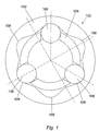
- Fig. 1 shows a prior art ball and cam ring arrangement 100 comprising an outer clutch ring 102, an inner clutch ring 104 and three clutch balls 106 urged radially outwards by biasing means.
- the biasing means can be in the form of a torque limiting ball of much larger diameter than the clutch balls and which is urged against the clutch balls by, for example, a coil spring.
- the action of the torque-limiting ball against the clutch balls 106 serves to urge the clutch balls 106 radially outwardly against cammed indentations 108 on the inner surface of the outer clutch ring 102.
- the outer clutch ring 102 is coupled to a handle of a tool and the inner clutch ring 104 is coupled to a screw engaging shaft of the tool.
- the clutch balls 106 are urged radially outwardly and couple the outer clutch ring 102 to the inner clutch ring 104, and therefore the handle to the screw engaging shaft. In this position the clutch balls 106 act upon the profiled surface of the cammed indentations 108 of the inner face of the outer clutch ring 102.
- the resistance torque increases and this resistance torque translates to a force exerted on the clutch balls 106 by the outer clutch ring 102 through the cammed indentations 108.
- the radial component of this force on the clutch balls 106 eventually reaches a level where the force provided by the biasing means is overcome and the clutch balls 106 are moved radially inwardly out of contact with the cammed indentations 108.
- the outer clutch ring 102 and inner clutch ring 104 become uncoupled, and the handle of the torque screwdriver slips with respect to the screw engaging shaft.
- this slipping is bi-directional, i.e. clockwise or counter-clockwise rotation of the torque screwdriver which exceeds a certain load will result in slipping.
- the user may want the torque screwdriver to slip in only one direction, i.e. when driving a fastener into a substrate but not when unscrewing the fastener.
- a clutch mechanism comprising an outer clutch ring, an inner clutch ring and at least one clutch ball interposed between the inner clutch ring and outer clutch ring, said at least one clutch ball engaging a profiled indentation in one of said clutch rings and being driven by the other of said clutch rings, whereby torque can be transmitted from one of said clutch rings to the other of said clutch rings, wherein the profile of said indentation is such that the torque transmitted is limited to a pre-set level in one direction of torque transmission and is above said level in the opposite direction of torque transmission.
- a torque screwdriver including a clutch mechanism as set out in the last preceding paragraph.
- the clutch mechanism 18 comprises an outer clutch ring 30, an inner clutch ring 32 and three clutch balls 34.
- the outer clutch ring 30 is provided with six cammed indentations 36 equidistantly spaced around the inner surface of the outer clutch ring 30.
- the inner clutch ring has three clutch ball slots 38. Each ball slot 38 has a torque-limit face 48 and an opposed lock face 50.
- the three clutch balls 34 are acted upon by torque-limiting biasing means (not shown) which acts to urge the balls 34 radially outwardly through clutch ball slots 38 formed in the inner clutch ring 32 into contact with the cammed indentations 36.
- the cammed indentations 34 are asymmetrical, having a torque limit profile 40 counter-clockwise of the centre of the cammed indentations 36 and a lock profile 42 clockwise of the centre of the cammed indentations 36.
- the torque-limit profile 40 of the cammed indentations 36 is profiled to an extent similar to that used in previously proposed designs as is known in the art.
- the lock profile 42 has a profile which closely follows the outer surface of the clutch ball 34 terminating at a lock shoulder 46 on the inner surface 44 of the outer clutch ring 30.
- the clutch ball slots 38 are also asymmetrical.
- the torque-limit face 48 which urges the clutch ball 34 against the torque-limit profile 40 of the cammed indentation 36, is similar in general form to prior art slots.
- the torque-limit face 48 is generally parallel to a line drawn from the centre of the clutch mechanism 18 to the centre of the clutch ball 34 when the torque-limit face 48 abuts said clutch ball 34. This allows the clutch ball 34 to move towards the centre of the clutch mechanism 18 when the resultant force from the resistance torque exceeds the radially outward force provided by the torque-limiting biasing means.
- the lock face 50 of the clutch ball slot 38 is formed at an angle to the line drawn from the centre of the clutch mechanism 18 to the centre of a clutch ball 34 when the lock face 50 abuts the clutch ball 34.
- the angle of the face 40 is such as to urge the the clutch ball radially outwardly when the lock face 50 contacts the ball 34.
- the clutch ball 34 moves radially inwardly down the profile of the torque limit profile 40, ie towards the centre of the clutch mechanism 18, thus "disconnecting" the outer and inner rings and allowing the outer ring 30 to move relative to the inner ring 32.
- the lock face 50 is angled as described above and, in addition, is cut away as shown at 54 to provide a point of contact of the lock face 50 which lies between the inner edge of the clutch ball slot 38 and the circumference passing through the centre 60 of the clutch ball 34.
- a torque screwdriver 10 comprising a handle 12, a shaft 14 and a bit receiving socket 16.
- the handle 12 and shaft 14 are connected by a clutch mechanism 18 as described above with reference to Fig. 2.
- the torque screwdriver 10 includes in the handle 12, a torque-limiting biasing means 19 comprising a coil spring 20, a rotatable setting assembly 22, a thrust ring 24 and a torque-limiting ball 26.
- the torque-limiting ball 26 exerts a force upon the clutch balls 34 urging the balls 34 radially outwards.
- the level of the biasing force provided by the biasing means 19 determines the breaking torque of the torque screwdriver 10 and is adjusted by movement of the rotatable setting assembly 22.
- the position of the rotatable setting assembly 22 along the handle 12 is adjusted by a setting tool 28 which adjusts the pre-load of the coil spring 20 and thereby varies the force acting upon the torque-limiting ball 26 and thus the force urging the clutch balls 34 radially outwards.
- Rotation of the handle 14, which is drivingly attached to the outer clutch ring 30 in a clockwise direction results in the torque screwdriver 10 operating as a traditional torque screwdriver, i.e. the clutch mechanism 18 will slip once a predetermined resistance torque is reached.
- Counter-clockwise rotation results in the torque screwdriver 10 operating as a standard screwdriver with no slippage of the clutch mechanism 18.
- the present invention provides a torque screwdriver that only limits the maximum torque that can be applied in one direction.
- the embodiment described above relates to a clutch mechanism having three clutch balls and six cammed indentations. It will be understood that this number can be readily modified and may be, for example, three clutch balls and three cammed indentations.
Landscapes
- Engineering & Computer Science (AREA)
- Mechanical Engineering (AREA)
- General Engineering & Computer Science (AREA)
- Details Of Spanners, Wrenches, And Screw Drivers And Accessories (AREA)
Applications Claiming Priority (2)
| Application Number | Priority Date | Filing Date | Title |
|---|---|---|---|
| GB0310796 | 2003-05-10 | ||
| GB0310796A GB0310796D0 (en) | 2003-05-10 | 2003-05-10 | A clutch mechanism for a torque screwdriver |
Publications (2)
| Publication Number | Publication Date |
|---|---|
| EP1477278A2 true EP1477278A2 (de) | 2004-11-17 |
| EP1477278A3 EP1477278A3 (de) | 2006-10-04 |
Family
ID=9957838
Family Applications (1)
| Application Number | Title | Priority Date | Filing Date |
|---|---|---|---|
| EP04251030A Withdrawn EP1477278A3 (de) | 2003-05-10 | 2004-02-25 | Kupplungsmechanismus für einen Drehmoment-Schraubenzieher |
Country Status (2)
| Country | Link |
|---|---|
| EP (1) | EP1477278A3 (de) |
| GB (1) | GB0310796D0 (de) |
Cited By (2)
| Publication number | Priority date | Publication date | Assignee | Title |
|---|---|---|---|---|
| DE102006046066A1 (de) * | 2006-06-27 | 2008-01-03 | KO-KEN TOOL CO., LTD., Shizuoka | Drehmomentadapter für einen Steckschlüssel |
| EP2898989A4 (de) * | 2012-09-21 | 2016-07-06 | Nitto Kohki Co | Elektrischer schraubenzieher |
Families Citing this family (1)
| Publication number | Priority date | Publication date | Assignee | Title |
|---|---|---|---|---|
| CN107584449B (zh) * | 2017-09-26 | 2019-03-15 | 北京无线电测量研究所 | 一种用于拧紧螺纹连接件的可调扭矩转接装置 |
Citations (8)
| Publication number | Priority date | Publication date | Assignee | Title |
|---|---|---|---|---|
| GB856136A (en) * | 1956-03-26 | 1960-12-14 | M H H Engineering Company Ltd | Torque limiting wrenches |
| GB893932A (en) * | 1959-01-29 | 1962-04-18 | Albert Allen Baker | Torque limit clutch for a wall hydrant |
| US3187865A (en) * | 1962-12-21 | 1965-06-08 | Skil Corp | Predetermined torque release tool with non-ratcheting feature |
| US4262501A (en) * | 1977-04-14 | 1981-04-21 | Vsi Corporation | Torque control installation and removal tool |
| DE3704764A1 (de) * | 1986-03-13 | 1987-09-17 | Polygraph Leipzig | Einrichtung zum einstellen einer drehmomentbegrenzung an einem schraubendreher |
| EP0532289A1 (de) * | 1991-09-10 | 1993-03-17 | Mhh Engineering Co Ltd | Vorrichtung zum Ausüben eines Drehmoments auf einem Befestigungsmittel |
| DE19507558A1 (de) * | 1994-03-03 | 1995-09-07 | Facom | Dynamometrisches Werkzeug |
| DE19903863A1 (de) * | 1999-02-01 | 2000-08-24 | Bosch Gmbh Robert | Sicherheitskupplung |
-
2003
- 2003-05-10 GB GB0310796A patent/GB0310796D0/en not_active Ceased
-
2004
- 2004-02-25 EP EP04251030A patent/EP1477278A3/de not_active Withdrawn
Patent Citations (8)
| Publication number | Priority date | Publication date | Assignee | Title |
|---|---|---|---|---|
| GB856136A (en) * | 1956-03-26 | 1960-12-14 | M H H Engineering Company Ltd | Torque limiting wrenches |
| GB893932A (en) * | 1959-01-29 | 1962-04-18 | Albert Allen Baker | Torque limit clutch for a wall hydrant |
| US3187865A (en) * | 1962-12-21 | 1965-06-08 | Skil Corp | Predetermined torque release tool with non-ratcheting feature |
| US4262501A (en) * | 1977-04-14 | 1981-04-21 | Vsi Corporation | Torque control installation and removal tool |
| DE3704764A1 (de) * | 1986-03-13 | 1987-09-17 | Polygraph Leipzig | Einrichtung zum einstellen einer drehmomentbegrenzung an einem schraubendreher |
| EP0532289A1 (de) * | 1991-09-10 | 1993-03-17 | Mhh Engineering Co Ltd | Vorrichtung zum Ausüben eines Drehmoments auf einem Befestigungsmittel |
| DE19507558A1 (de) * | 1994-03-03 | 1995-09-07 | Facom | Dynamometrisches Werkzeug |
| DE19903863A1 (de) * | 1999-02-01 | 2000-08-24 | Bosch Gmbh Robert | Sicherheitskupplung |
Cited By (3)
| Publication number | Priority date | Publication date | Assignee | Title |
|---|---|---|---|---|
| DE102006046066A1 (de) * | 2006-06-27 | 2008-01-03 | KO-KEN TOOL CO., LTD., Shizuoka | Drehmomentadapter für einen Steckschlüssel |
| EP2898989A4 (de) * | 2012-09-21 | 2016-07-06 | Nitto Kohki Co | Elektrischer schraubenzieher |
| US9902051B2 (en) | 2012-09-21 | 2018-02-27 | Nitto Kohki Co., Ltd. | Electric screwdriver |
Also Published As
| Publication number | Publication date |
|---|---|
| EP1477278A3 (de) | 2006-10-04 |
| GB0310796D0 (en) | 2003-06-18 |
Similar Documents
| Publication | Publication Date | Title |
|---|---|---|
| US7650821B2 (en) | Torque-limiting mechanism | |
| US7455123B2 (en) | Hand-held power tool with a torque-limiting unit | |
| US6672183B2 (en) | Quick release for use with impact wrench | |
| US5673758A (en) | Low-noise impact screwdriver | |
| US20060244224A1 (en) | Rotatable chuck | |
| US20090194305A1 (en) | Power tool | |
| EP2745988B1 (de) | Handwerkzeugmaschine mit Drehmomentbegrenzereinheit | |
| EP1737620B1 (de) | Drehmomentbegrenzungsgriff | |
| US6152000A (en) | Driver bit and driver | |
| JPH06114749A (ja) | 携帯電動工具 | |
| US20130081518A1 (en) | Extraction device and method | |
| US11453103B2 (en) | Locking clutch ratchet wrenches | |
| US4610339A (en) | Adjustable torque limiting assembly | |
| US3547242A (en) | Torque limiting devices or overload clutches | |
| EP1477278A2 (de) | Kupplungsmechanismus für einen Drehmoment-Schraubenzieher | |
| US9555526B1 (en) | Selectively lockable torque-limiting mechanism | |
| USRE33514E (en) | Adjustable torque limiting assembly | |
| CN112677087A (zh) | 可转位的棘轮工具 | |
| US20060024142A1 (en) | Torque-limiting stud | |
| CN115701376A (zh) | 防空程保持套筒 | |
| EP1498627A1 (de) | Drehmomentbegrenzungskupplung. | |
| GB2370077A (en) | Torque limiting clutch with manual disengagement means | |
| US20050139445A1 (en) | Wedge clutch assembly | |
| GB2152600A (en) | Adjustable torque-limiting assembly | |
| US20190015958A1 (en) | Locking Clutch Ratchet Wrenches |
Legal Events
| Date | Code | Title | Description |
|---|---|---|---|
| PUAI | Public reference made under article 153(3) epc to a published international application that has entered the european phase |
Free format text: ORIGINAL CODE: 0009012 |
|
| AK | Designated contracting states |
Kind code of ref document: A2 Designated state(s): AT BE BG CH CY CZ DE DK EE ES FI FR GB GR HU IE IT LI LU MC NL PT RO SE SI SK TR |
|
| AX | Request for extension of the european patent |
Extension state: AL HR LT LV MK |
|
| PUAL | Search report despatched |
Free format text: ORIGINAL CODE: 0009013 |
|
| AK | Designated contracting states |
Kind code of ref document: A3 Designated state(s): AT BE BG CH CY CZ DE DK EE ES FI FR GB GR HU IE IT LI LU MC NL PT RO SE SI SK TR |
|
| AX | Request for extension of the european patent |
Extension state: AL LT LV MK |
|
| AKX | Designation fees paid | ||
| REG | Reference to a national code |
Ref country code: DE Ref legal event code: 8566 |
|
| STAA | Information on the status of an ep patent application or granted ep patent |
Free format text: STATUS: THE APPLICATION IS DEEMED TO BE WITHDRAWN |
|
| 18D | Application deemed to be withdrawn |
Effective date: 20070405 |